

Page 1
Operation, Safety, and
Maintenance Manual
Keep this manual with the machine at all times.
Model
67SL
ANSI
®
P/N - 3121321
September 25, 2008
Page 2

Page 3

FOREWORD
FOREWORD
This manual is a very important tool! Keep it with the machine at all times.
The purpose of this manual is to provide owners, users, operators, lessors, and lessees with the precautions and
operating procedures essential for the safe and proper machine operation for its intended purpose.
Due to continuous product improvements, JLG Industries, Inc. reserves the right to make specification changes
without prior notification. Contact JLG Industries, Inc. for updated information.
3121321 – JLG Lift – a
Page 4
FOREWORD
SAFETY ALERT SYMBOLS AND SAFETY SIGNAL WORDS
This is the Safety Alert Symbol. It is used to alert you to the potential personal
injury hazards. Obey all safety messages that follow this symbol to avoid possible
injury or death
INDICATES AN IMMINENTLY HAZARDOUS SITUATION. IF NOT
AVOIDED, WILL RESULT IN SERIOUS INJURY OR DEATH. THIS DECAL
WILL HAVE A RED BACKGROUND.
INDICATES A POTENTIALITY HAZARDOUS SITUATION. IF NOT
AVOIDED, COULD
DECAL WILL HAVE AN ORANGE BACKGROUND.
RESULT IN SERIOUS INJURY OR DEATH. THIS
INDICATES A POTENTIALITY HAZARDOUS SITUATION. IF NOT
AVOIDED, MAY RESULT IN MINOR OR MODERATE INJURY. IT MAY
ALSO ALERT AGAINST UNSAFE PRACTICES. THIS DECAL WILL HAVE
A YELLOW BACKGROUND.
b – JLG Lift – 3121321
Page 5

THIS PRODUCT MUST COMPLY WITH ALL SAFETY RELATED BULLETINS. CONTACT JLG INDUSTRIES, INC. OR THE LOCAL AUTHORIZED
JLG REPRESENTATIVE FOR INFORMATION REGARDING SAFETYRELATED BULLETINS WHICH MAY HAVE BEEN ISSUED FOR THIS
PRODUCT.
NOTICE
JLG INDUSTRIES, INC. SENDS SAFETY RELATED BULLETINS TO THE
OWNER OF RECORD OF THIS MACHINE. CONTACT JLG INDUSTRIES,
INC. TO ENSURE THAT THE CURRENT OWNER RECORDS ARE
UPDATED AND ACCURATE.
NOTICE
JLG INDUSTRIES, INC. MUST BE NOTIFIED IMMEDIATELY IN ALL
INSTANCES WHERE JLG PRODUCTS HAVE BEEN INVOLVED IN AN
ACCIDENT INVOLVING BODILY INJURY OR DEATH OF PERSONNEL
OR WHEN SUBSTANTIAL DAMAGE HAS OCCURRED TO PERSONAL
PROPERTY OR THE JLG PRODUCT.
For:
• Accident Reporting
• Product Safety Publications
• Current Owner Updates
• Questions Regarding
Product Safety
• Standards and Regulations
Compliance Information
• Questions Regarding Special Product Applications
• Questions Regarding Product Modifications
Contact:
Product Safety and Reliability Department
JLG Industries, Inc.
13224 Fountainhead Plaza
Hagerstown, MD 21742
or Your Local JLG Office
(See addresses on manual rear cover)
In USA:
Toll Free: 877-JLG-SAFE (877-554-7233)
Outside USA:
Phone: 240-420-2661
E-mail: ProductSafety@JLG.com
FOREWORD
3121321 – JLG Lift – c
Page 6

FOREWORD
REVISION LOG
Original Issue - September 28, 2006
Revised - October 25, 2006
Revised - December 21, 2006
Revised - March 7, 2007
Revised - March 28, 2007
Revised - May 13, 2008
Revised - September 25, 2008
d – JLG Lift – 3121321
Page 7

TABLE OF CONTENTS
SECTION - PARAGRAPH, SUBJECT PAGE SECTION - PARAGRAPH, SUBJECT PAGE
SECTION - 1 - SAFETY PRECAUTIONS
1.1 GENERAL . . . . . . . . . . . . . . . . . . . . . . . . . . . . . . . . .1-1
1.2 PRE-OPERATION . . . . . . . . . . . . . . . . . . . . . . . . . . .1-1
Operator Training and Knowledge. . . . . . . . . . . 1-1
Workplace Inspection. . . . . . . . . . . . . . . . . . . . . 1-2
Machine Inspection . . . . . . . . . . . . . . . . . . . . . . 1-3
1.3 OPERATION . . . . . . . . . . . . . . . . . . . . . . . . . . . . . . .1-3
General . . . . . . . . . . . . . . . . . . . . . . . . . . . . . . . . 1-3
Trip and Fall Hazards . . . . . . . . . . . . . . . . . . . . . 1-4
Electrocution Hazards . . . . . . . . . . . . . . . . . . . . 1-5
Tipping Hazards . . . . . . . . . . . . . . . . . . . . . . . . . 1-7
Crushing and Collision Hazards. . . . . . . . . . . . . 1-8
1.4 TOWING, LIFTING, AND HAULING . . . . . . . . . . . . .1-9
1.5 MAINTENANCE . . . . . . . . . . . . . . . . . . . . . . . . . . . .1-9
General . . . . . . . . . . . . . . . . . . . . . . . . . . . . . . . . 1-9
Maintenance Hazards. . . . . . . . . . . . . . . . . . . . 1-10
Battery Hazards . . . . . . . . . . . . . . . . . . . . . . . . 1-10
SECTION - 2 - USER RESPONSIBILITIES, MACHINE PREPARATION AND INSPECTION
2.1 PERSONNEL TRAINING . . . . . . . . . . . . . . . . . . . . .2-1
Operator Training . . . . . . . . . . . . . . . . . . . . . . . . 2-1
Training Supervision. . . . . . . . . . . . . . . . . . . . . . 2-1
Operator Responsibility. . . . . . . . . . . . . . . . . . . . 2-1
2.2 PREPARATION, INSPECTION, AND
MAINTENANCE. . . . . . . . . . . . . . . . . . . . . . . . . . . 2-2
2.3 PRE-START INSPECTION. . . . . . . . . . . . . . . . . . . . 2-4
Function Check . . . . . . . . . . . . . . . . . . . . . . . . . . 2-5
Limit Switches . . . . . . . . . . . . . . . . . . . . . . . . . . . 2-6
General . . . . . . . . . . . . . . . . . . . . . . . . . . . . . . . . 2-9
SECTION - 3 - MACHINE CONTROLS
3.1 GENERAL . . . . . . . . . . . . . . . . . . . . . . . . . . . . . . . . 3-1
3.2 OPERATING CHARACTERISTICS AND
LIMITATIONS. . . . . . . . . . . . . . . . . . . . . . . . . . . . . 3-1
General . . . . . . . . . . . . . . . . . . . . . . . . . . . . . . . . 3-1
Placards. . . . . . . . . . . . . . . . . . . . . . . . . . . . . . . . 3-1
Capacities . . . . . . . . . . . . . . . . . . . . . . . . . . . . . . 3-2
3.3 CONTROLS AND INDICATORS . . . . . . . . . . . . . . . 3-2
Ground Control Stations . . . . . . . . . . . . . . . . . . 3-2
Main Terminal Box. . . . . . . . . . . . . . . . . . . . . . . . 3-5
Ground Control Console . . . . . . . . . . . . . . . . . . . 3-7
3.4 PLATFORM CONTROL CONSOLE . . . . . . . . . . . . 3-9
SECTION - 4 - MACHINE OPERATION
4.1 DESCRIPTION. . . . . . . . . . . . . . . . . . . . . . . . . . . . . 4-1
3121321 – JLG Lift – i
Page 8

TABLE OF CONTENTS
SECTION - PARAGRAPH, SUBJECT PAGE SECTION - PARAGRAPH, SUBJECT PAGE
General Description of the Functions and
Components. . . . . . . . . . . . . . . . . . . . . . . . . . 4-1
4.2 STARTING . . . . . . . . . . . . . . . . . . . . . . . . . . . . . . . . 4-1
4.3 LIFTING AND LOWERING . . . . . . . . . . . . . . . . . . . . 4-2
4.4 AUTOMATIC SELF LEVELING CHASSIS . . . . . . . . 4-3
4.5 DRIVING THE MACHINE FROM THE PLATFORM . 4-4
4.6 STEERING . . . . . . . . . . . . . . . . . . . . . . . . . . . . . . . . 4-6
4.7 HYDRAULIC PLATFORM EXTENSION . . . . . . . . . . 4-6
4.8 EMERGENCY LOWERING - MANUAL DESCENT . 4-6
4.9 PARKING AND STOWING . . . . . . . . . . . . . . . . . . . . 4-6
4.10 TIE DOWN/LIFT LUGS. . . . . . . . . . . . . . . . . . . . . . . 4-7
Tie Down . . . . . . . . . . . . . . . . . . . . . . . . . . . . . . 4-7
Lifting . . . . . . . . . . . . . . . . . . . . . . . . . . . . . . . . . 4-7
4.11 TRANSPORT AND STORAGE OF THE MACHINE . 4-8
SECTION - 5 - EMERGENCY PROCEDURES
5.1 GENERAL . . . . . . . . . . . . . . . . . . . . . . . . . . . . . . . . 5-1
Emergency Stop Switch . . . . . . . . . . . . . . . . . . 5-1
Platform Caught Overhead . . . . . . . . . . . . . . . . 5-1
Righting of Tipped Machine. . . . . . . . . . . . . . . . 5-1
Post-Incident Inspection . . . . . . . . . . . . . . . . . . 5-1
5.2 EMERGENCY OPERATION. . . . . . . . . . . . . . . . . . . 5-2
Operator Unable to Control Machine . . . . . . . . . 5-2
Incident Notification . . . . . . . . . . . . . . . . . . . . . . 5-2
5.3 MANUAL PROCEDURES . . . . . . . . . . . . . . . . . . . . .5-3
Manual Platform Deck Retraction. . . . . . . . . . . . 5-3
Manual Platform Lowering (Prior to
S/N 1200021189) . . . . . . . . . . . . . . . . . . . . . . . 5-5
Manual Platform Lowering (S/N 1200021189 to
Present) . . . . . . . . . . . . . . . . . . . . . . . . . . . . . . 5-6
5.4 EMERGENCY TOWING . . . . . . . . . . . . . . . . . . . . . .5-7
Prior to Towing . . . . . . . . . . . . . . . . . . . . . . . . . . 5-7
SECTION - 6 - GENERAL SPECIFICATIONS AND OPERATOR
MAINTENANCE
6.1 INTRODUCTION. . . . . . . . . . . . . . . . . . . . . . . . . . . .6-1
6.2 OPERATING SPECIFICATIONS . . . . . . . . . . . . . . .6-2
Dimensional Data . . . . . . . . . . . . . . . . . . . . . . . 6-3
Capacities . . . . . . . . . . . . . . . . . . . . . . . . . . . . . 6-3
Tires . . . . . . . . . . . . . . . . . . . . . . . . . . . . . . . . . . 6-3
Engine . . . . . . . . . . . . . . . . . . . . . . . . . . . . . . . . 6-4
Component Weights . . . . . . . . . . . . . . . . . . . . . 6-4
Lubrication . . . . . . . . . . . . . . . . . . . . . . . . . . . . . 6-7
6.3 OPERATOR MAINTENANCE . . . . . . . . . . . . . . . . . .6-8
6.4 TIRES AND WHEELS . . . . . . . . . . . . . . . . . . . . . . .6-13
ii – JLG Lift – 3121321
Page 9

TABLE OF CONTENTS
SECTION - PARAGRAPH, SUBJECT PAGE SECTION - PARAGRAPH, SUBJECT PAGE
Tire Damage . . . . . . . . . . . . . . . . . . . . . . . . . . . 6-13
Tire Replacement . . . . . . . . . . . . . . . . . . . . . . . 6-13
Wheel Replacement . . . . . . . . . . . . . . . . . . . . . 6-14
Wheel Installation . . . . . . . . . . . . . . . . . . . . . . . 6-14
SECTION - 7 - INSPECTION AND REPAIR LOG
List of Figures
2-1. Limit Switch Locations . . . . . . . . . . . . . . . . . . . . . . 2-7
2-2. Walk - Around Inspection Diagram. . . . . . . . . . . . . 2-8
2-3. Walk - Around Inspection Points (Sheet 1) . . . . . . 2-9
2-4. Walk - Around Inspection Points (Sheet 2) . . . . . 2-10
3-1. Side Compartment Electrical Tray . . . . . . . . . . . . . 3-2
3-2. Engine Control . . . . . . . . . . . . . . . . . . . . . . . . . . . . 3-3
3-3. Main Terminal Box . . . . . . . . . . . . . . . . . . . . . . . . . 3-5
3-4. Ground Control Console . . . . . . . . . . . . . . . . . . . . 3-7
3-5. Platform Control Console . . . . . . . . . . . . . . . . . . . . 3-9
3-6. Decal Location (ANSI) - Sheet 1 of 2 . . . . . . . . . . 3-12
3-7. Decal Location (ANSI) - Sheet 2 of 2 . . . . . . . . . . 3-13
3-8. Decal Location (CSA) - Sheet 1 of 2. . . . . . . . . . . 3-14
3-9. Decal Location (CSA) - Sheet 2 of 2. . . . . . . . . . . 3-15
4-1. Grade and Sideslope . . . . . . . . . . . . . . . . . . . . . . . 4-5
4-2. Lifting and Tie Down Points . . . . . . . . . . . . . . . . . . 4-7
5-1. Drive Disconnect Hub. . . . . . . . . . . . . . . . . . . . . . . 5-8
6-1. Engine Operating Temperature Specifications -
Sheet 1 of 2 . . . . . . . . . . . . . . . . . . . . . . . . . . . . . 6-5
6-2. Engine Operating Temperature Specifications -
Sheet 2 of 2 . . . . . . . . . . . . . . . . . . . . . . . . . . . . . 6-6
6-3. Operator Maintenance and Lubrication Diagram. . 6-8
3121321 – JLG Lift – iii
Page 10

TABLE OF CONTENTS
SECTION - PARAGRAPH, SUBJECT PAGE SECTION - PARAGRAPH, SUBJECT PAGE
List of Tables
1-1 Minimum Approach Distances (M.A.D.) . . . . . . . . . 1-6
2-1 Inspection and Maintenance Table . . . . . . . . . . . . . 2-3
2-2 Cutout Switch Limits . . . . . . . . . . . . . . . . . . . . . . . . 2-6
3-1 Decal Legend. . . . . . . . . . . . . . . . . . . . . . . . . . . . . 3-16
6-1 Operating Specifications . . . . . . . . . . . . . . . . . . . . .6-2
6-2 Dimensional Data. . . . . . . . . . . . . . . . . . . . . . . . . . . 6-3
6-3 Capacities . . . . . . . . . . . . . . . . . . . . . . . . . . . . . . . . 6-3
6-4 Tire Specifications . . . . . . . . . . . . . . . . . . . . . . . . . . 6-3
6-5 Engine Specifications . . . . . . . . . . . . . . . . . . . . . . . 6-4
6-6 Engine Battery Specifications . . . . . . . . . . . . . . . . . 6-4
6-7 Component Weights . . . . . . . . . . . . . . . . . . . . . . . . 6-4
6-8 Hydraulic Oil . . . . . . . . . . . . . . . . . . . . . . . . . . . . . . 6-7
6-9 Lubrication Specifications . . . . . . . . . . . . . . . . . . . . 6-7
7-1 Inspection and Repair Log . . . . . . . . . . . . . . . . . . .7-1
iv – JLG Lift – 3121321
Page 11
1.1 GENERAL
SECTION 1 - SAFETY PRECAUTIONS
SECTION 1. SAFETY PRECAUTIONS
This section outlines the necessary precautions for proper
and safe machine usage and maintenance. In order to promote proper machine usage, it is mandatory that a daily routine is established based on the content of this manual. A
maintenance program, using the information provided in this
manual and the Service and Maintenance Manual, must also
be established by a qualified person and must be followed to
ensure that the machine is safe to operate.
The owner/user/operator/lessor/lessee of the machine
should not accept operating responsibility until this manual
has been read, training is accomplished, and operation of
the machine has been completed under the supervision of
an experienced and qualified operator.
These sections contain the responsibilities of the owner,
user, operator, lessor, and lessee concerning safety, training,
inspection, maintenance, application, and operation.If there
are any questions with regard to safety, training, inspection,
maintenance, application, and operation, please contact JLG
Industries, Inc. (“JLG”).
FAILURE TO COMPLY WITH THE SAFETY PRECAUTIONS LISTED IN
THIS MANUAL COULD RESULT IN MACHINE DAMAGE, PROPERTY
DAMAGE, PERSONAL INJURY OR DEATH.
1.2 PRE-OPERATION
Operator Training and Knowledge
• The Operators and Safety Manual must be read in its
entirety before operating the machine. For clarification,
questions, or additional information regarding any portions of this manual, contact JLG Industries, Inc.
3121321 – JLG Lift – 1-1
Page 12

SECTION 1 - SAFETY PRECAUTIONS
• An operator must not accept operating responsibilities
until adequate training has been given by competent and
authorized persons.
• Allow only those authorized and qualified personnel to
operate the machine who have demonstrated that they
understand the safe and proper operation and maintenance of the unit.
• Read, understand, and obey all DANGERS, WARNINGS,
CAUTIONS, and operating instructions on the machine
and in this manual.
• Ensure that the machine is to be used in a manner which
is within the scope of its intended application as determined by JLG.
• All operating personnel must be familiar with the emergency controls and emergency operation of the machine
as specified in this manual.
• Read, understand, and obey all applicable employer,
local, and governmental regulations as they pertain to
your utilization and application of the machine.
Workplace Inspection
• Precautions to avoid all hazards in the work area must be
taken by the user before operation of the machine.
• Do not operate or raise the platform from a position on
trucks, trailers, railway cars, floating vessels, scaffolds or
other equipment unless the application is approved in
writing by JLG.
• Before operation, check work area for overhead hazards
such as electric lines, bridge cranes, and other potential
overhead obstructions.
• Check floor surfaces for holes, bumps, drop-offs, obstructions, debris, concealed holes, and other potential hazards.
• Check the work area for hazardous locations. Do not
operate the machine in hazardous environments unless
approved for that purpose by JLG.
• Ensure that the ground conditions are adequate to support the maximum tire load indicated on the tire load
decals located on the chassis adjacent to each wheel.
• Do not operate the machine when wind conditions exceed
28 mph (12.5 m/s).
• This machine can be operated in nominal ambient tem-
peratures of 5
optimize operation outside of this temperature range.
o
F to 113oF (-15oC to 45oC). Consult JLG to
1-2 – JLG Lift – 3121321
Page 13

SECTION 1 - SAFETY PRECAUTIONS
Machine Inspection
• Do not operate this machine until the inspections and
functional checks have been performed as specified in
Section 2 of this manual.
• Do not operate this machine until it has been serviced and
maintained according to the maintenance and inspection
requirements as specified in the machine’s Service and
Maintenance Manual.
• Ensure all safety devices are operating properly. Modification of these devices is a safety violation.
MODIFICATION OR ALTERATION OF AN AERIAL WORK PLATFORM
SHALL BE MADE ONLY WITH PRIOR WRITTEN PERMISSION FROM THE
MANUFACTURER
• Do not operate any machine on which the safety or
instruction placards or decals are missing or illegible.
• Check the machine for modifications to original components. Ensure that any modifications have been approved
by JLG.
• Avoid accumulation of debris on platform deck. Keep
mud, oil, grease, and other slippery substances from footwear and platform deck.
1.3 OPERATION
General
• Do not use the machine for any purpose other than positioning personnel, their tools, and equipment.
• Before operation, the user must be familiar with the
machine capabilities and operating characteristics of all
functions.
• Never operate a malfunctioning machine. If a malfunction
occurs, shut down the machine. Remove the unit from
service and notify the proper authorities.
• Do not remove, modify, or disable any safety devices.
• Never slam a control switch or lever through neutral to an
opposite direction. Always return switch to neutral and
stop before moving the switch to the next function. Operate controls with slow and even pressure.
• Do not allow personnel to tamper with or operate the
machine from the ground with personnel in the platform,
except in an emergency.
• Do not carry materials directly on platform railing unless
approved by JLG.
• When two or more persons are in the platform, the operator shall be responsible for all machine operations.
3121321 – JLG Lift – 1-3
Page 14
SECTION 1 - SAFETY PRECAUTIONS
• Always ensure that power tools are properly stowed and
never left hanging by their cord from the platform work
area.
• Do not assist a stuck or disabled machine by pushing or
pulling except by pulling at the chassis tie-down lugs.
• Stow scissor arm assembly and shut off all power before
leaving machine.
Trip and Fall Hazards
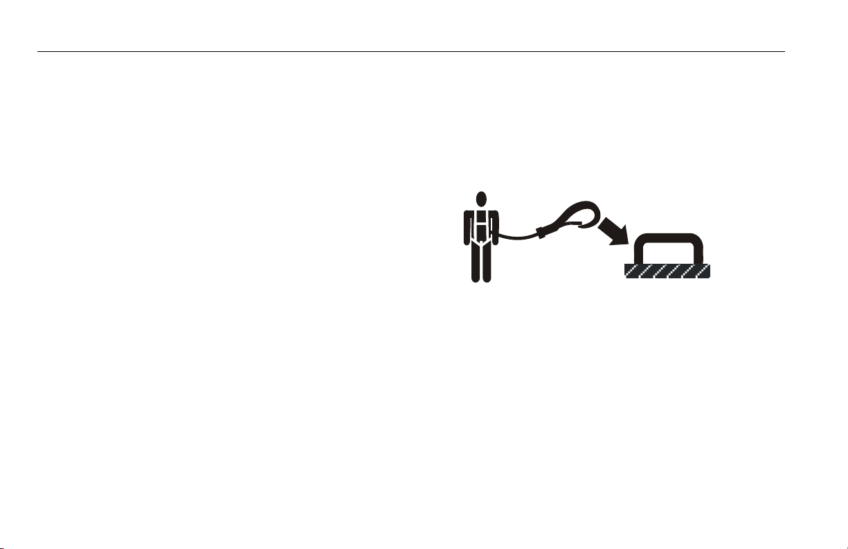
• JLG Industries, Inc. recommends that all persons in the
platform wear a full body harness with a lanyard attached
to an authorized lanyard anchorage point while operating
this machine. For further information regarding fall protection requirements on JLG products, contact JLG Industries, Inc.
• Prior to operation, ensure all gates and rails are fastened
and secured in their proper position. Identify the designated lanyard anchorage point(s) at the platform and
securely attach the lanyard. Attach only one (1) lanyard
per lanyard anchorage point
1-4 – JLG Lift – 3121321
Page 15
SECTION 1 - SAFETY PRECAUTIONS
.
• Keep both feet firmly positioned on the platform floor at all
times. Never position ladders, boxes, steps, planks, or
similar items on unit to provide additional reach for any
purpose.
• Never use the scissor arm assembly to gain access to or
leave the platform.
• Use extreme caution when entering or leaving platform.
Ensure that the scissor arm assembly is fully lowered.
Face the machine when entering or leaving the platform.
Always maintain “three point contact” with the machine,
using two hands and one foot or two feet and one hand at
all times during entry and exit.
• Keep oil, mud, and slippery substances cleaned from footwear and the platform floor.
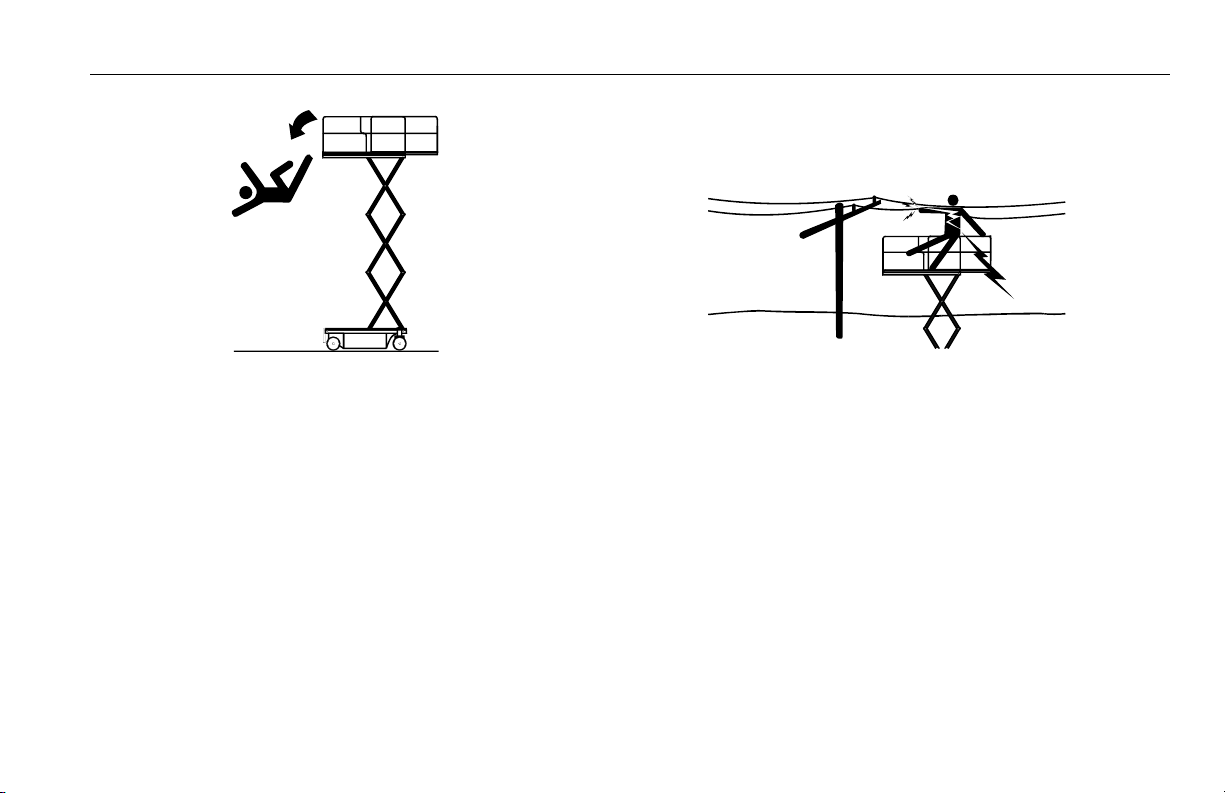
Electrocution Hazards
• This machine is not insulated and does not provide protection from contact or proximity to electrical current.
3121321 – JLG Lift – 1-5
Page 16
SECTION 1 - SAFETY PRECAUTIONS
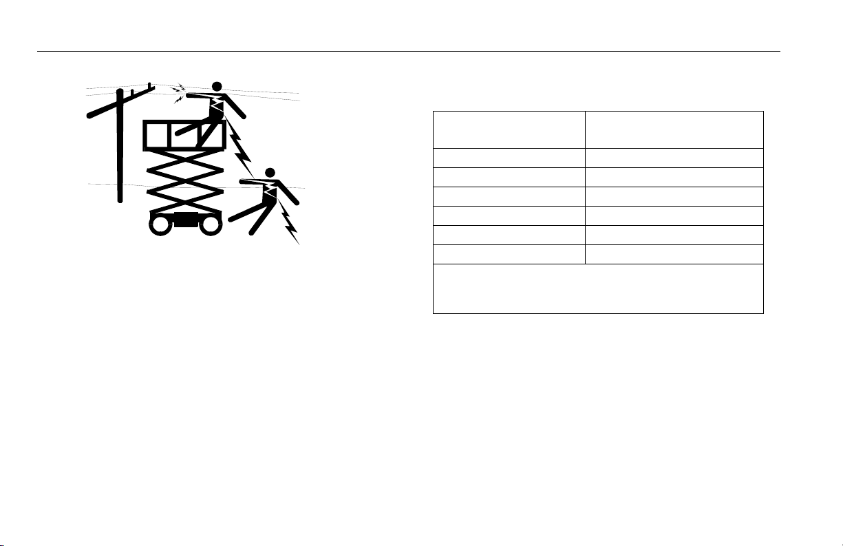
Table 1-1.Minimum Approach Distances (M.A.D.)
• Maintain safe clearance from electrical lines, apparatus, or
any energized (exposed or insulated) parts in accordance
with the Minimum Approach Distance (MAD) as specified
in Table 1-1.
• Allow for machine movement and electrical line swaying.
Voltage Range
(Phase to Phase)
0 to 50KV 10 (3)
Over 50 KV to 200 KV 15 (5)
Over 200KV to 350 KV 20 (6)
Over 350 KV to 500 KV 25 (8)
Over 500 KV to 750 KV 35 (11)
Over 750 KV to 1000 KV 45 (14)
NOTE: This requirement shall apply except where
employer, local or governmental regulations
are more stringent.
• Maintain a clearance of at least 10 ft (3 m) between any
part of the machine and its occupants, their tools, and
their equipment from any electrical line or apparatus carrying up to 50,000 volts. One foot additional clearance is
required for every additional 30,000 volts or less.
• The minimum approach distance may be reduced if insulating barriers are installed to prevent contact, and the
barriers are rated for the voltage of the line being guarded.
These barriers shall not be part of (or attached to) the
machine. The minimum approach distance shall be
MINIMUM APPROACH DISTANCE
in Feet (Meters)
1-6 – JLG Lift – 3121321
Page 17
SECTION 1 - SAFETY PRECAUTIONS
reduced to a distance within the designed working dimensions of the insulating barrier. This determination shall be
made by a qualified person in accordance with the
employer, local, or governmental requirements for work
practices near energized equipment.
DO NOT MANEUVER MACHINE OR PERSONNEL INSIDE PROHIBITED
ZONE (MAD). ASSUME ALL ELECTRICAL PARTS AND WIRING ARE
ENERGIZED UNLESS KNOWN OTHERWISE.
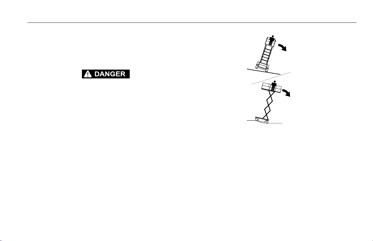
Tipping Hazards
• Ensure that the ground conditions are adequate to support the maximum tire load indicated on the tire load
decals located on the chassis adjacent to each wheel. Do
not travel on unsupported surfaces.
• The user should be familiar with the driving surface before
driving. Do not exceed the allowable sideslope and grade
while driving
.
• Do not elevate platform or drive with platform elevated
while on or near a sloping, uneven, or soft surface. Ensure
machine is positioned on a firm, level and uniformly supported surface before elevating platform or driving with
the platform in the elevated position.
• Before driving on floors, bridges, trucks, and other surfaces, check allowable capacity of the surfaces.
• Never exceed the maximum work load as specified on the
platform. Keep all loads within the confines of the platform, unless authorized by JLG.
3121321 – JLG Lift – 1-7
Page 18
SECTION 1 - SAFETY PRECAUTIONS
• Keep the chassis of the machine a minimum of 0.6 m (2 ft)
from holes, bumps, drop-offs, obstructions, debris, concealed holes, and other potential hazards at the ground
level.
• Never attempt to use the machine as a crane. Do not tieoff machine to any adjacent structure. Never attach wire,
cable, or any similar items to platform.
• Do not operate the machine when wind conditions exceed
the maximum allowable wind speed.
• Do not cover the platform sides or carry large surface-area
items in the platform when operating outdoors. The addition of such items increases the exposed wind area of the
machine.
• Do not increase the platform size with unauthorized deck
extensions or attachments.
• If scissor arm assembly or platform is caught so that one
or more wheels are off the ground, all persons must be
removed before attempting to free the machine. Use
cranes, forklift trucks, or other appropriate equipment to
stabilize machine and remove personnel.
Crushing and Collision Hazards
• Approved head gear must be worn by all operating and
ground personnel.
• Keep hands and limbs out of the scissor arm assembly
during operation.
• Watch for obstructions around machine and overhead
when driving. Check clearances above, on sides, and bottom of platform when lifting or lowering platform.
• During operation, keep all body parts inside platform railing.
• Always post a lookout when driving in areas where vision
is obstructed.
• Keep non-operating personnel at least 6 ft (1.8 m) away
from machine during all driving operations.
• Under all travel conditions, the operator must limit travel
speed according to conditions of ground surface, conges-
1-8 – JLG Lift – 3121321
Page 19

SECTION 1 - SAFETY PRECAUTIONS
tion, visibility, slope, location of personnel, and other factors causing hazards of collision or injury to personnel.
• Be aware of stopping distances in all drive speeds. When
driving in high speed, switch to low speed before stopping. Travel grades in low speed only.
• Do not use high speed drive in restricted or close quarters
or when driving in reverse.
• Exercise extreme caution at all times to prevent obstacles
from striking or interfering with operating controls and persons in the platform.
• Ensure that operators of other overhead and floor level
machines are aware of the aerial work platform’s presence. Disconnect power to overhead cranes. Barricade
floor area if necessary.
• Avoid operating over ground personnel. Warn personnel
not to work, stand, or walk under a raised platform. Position barricades on floor as necessary.
1.4 TOWING, LIFTING, AND HAULING
• Never allow personnel in platform while towing, lifting, or
hauling.
• This machine should not be towed, except in the event of
emergency, malfunction, power failure, or loading/unloading. Refer to emergency towing procedures.
• Ensure platform is fully retracted and completely empty of
tools prior to towing, lifting or hauling.
• Refer to Section 4 for lifting information.
1.5 MAINTENANCE
General
This section contains general safety precautions which must be
observed during maintenance of this machine. Additional precautions to be observed during machine maintenance are
inserted at the appropriate points in this maunual and in the Service and Maintenance Manual. It is of utmost importance that
maintenance personnel pay strict attention to these precautions
to avoid possible injury to personnel or damage to the machine
or property. A maintenance program must be established by a
qualified person and must be followed to ensure that the
machine is safe.
3121321 – JLG Lift – 1-9
Page 20

SECTION 1 - SAFETY PRECAUTIONS
Maintenance Hazards
• Shut off power to all controls and ensure that all operating
systems are secured from inadvertent motion prior to performing any adjustments or repairs.
• Never work under an elevated platform until it has been
fully lowered to the full down position, if possible, or otherwise supported and restrained from movement with
appropriate safety props, blocking, or overhead supports.
• Always relieve hydraulic pressure from all hydraulic circuits before loosening or removing hydraulic components.
• Always disconnect batteries when servicing electrical
components or when performing welding on the machine.
• Shut down the engine (if equipped) while fuel tanks are
being filled.
• Ensure replacement parts or components are identical or
equivalent to original parts or components.
• Never attempt to move heavy parts without the aid of a
mechanical device. Do not allow heavy objects to rest in
an unstable position. Ensure adequate support is provided when raising components of the machine.
• Remove all rings, watches, and jewelry when performing
any maintenance. Do not wear loose fitting clothing or
long hair unrestrained which may become caught or
entangled in equipment.
• Use only clean approved non-flammable cleaing solvents.
• Never alter, remove, or substitute any items such as counterweights, tires, batteries, platforms or other items that
may reduce or affect the overall weight or stability of the
machine.
• Reference the Service and Maintenance Manual for the
weights of critical stability items.
MODIFICATION OR ALTERATION OF AN AERIAL WORK PLATFORM
SHALL BE MADE ONLY WITH PRIOR WRITTEN PERMISSION FROM THE
MANUFACTURER.
Battery Hazards
• Always disconnect batteries when servicing electrical
components or when performing welding on the machine.
• Do not allow smoking, open flame, or sparks near battery
during charging or servicing.
• Do not contact tools or other metal objects across the battery terminals.
1-10 – JLG Lift – 3121321
Page 21

• Always wear hand, eye, and face protection when servicing batteries. Ensure that battery acid does not come in
contact with skin or clothing.
BATTERY FLUID IS HIGHLY CORROSIVE. AVOID CONTACT WITH SKIN
AND CLOTHING AT ALL TIMES. IMMEDIATELY RINSE ANY CONTACTED
AREA WITH CLEAN WATER AND SEEK MEDICAL ATTENTION.
• Charge batteries only in a well ventilated area.
• Avoid overfilling the battery fluid level. Add distilled water
to batteries only after the batteries are fully charged.
SECTION 1 - SAFETY PRECAUTIONS
3121321 – JLG Lift – 1-11
Page 22

SECTION 1 - SAFETY PRECAUTIONS
NOTES:
1-12 – JLG Lift – 3121321
Page 23

SECTION 2 - USER RESPONSIBILITIES, MACHINE PREPARATION AND INSPECTION
SECTION 2. USER RESPONSIBILITIES, MACHINE PREPARATION AND INSPECTION
2.1 PERSONNEL TRAINING
The aerial platform is a personnel handling device; so it is
necessary that it be operated and maintained only by trained
personnel.
Persons under the influence of drugs or alcohol or who are
subject to seizures, dizziness or loss of physical control must
not operate this machine.
Operator Training
Operator training must cover:
1. Use and limitations of the controls in the platform and at
the ground, emergency controls and safety systems.
2. Control labels, instructions, and warnings on the
machine.
3. Rules of the employer and government regulations.
4. Use of approved fall protection equipment.
5. Enough knowledge of the mechanical operation of the
machine to recognize a malfunction or potential malfunction.
6. The safest means to operate the machine where over-
head obstructions, other moving equipment, and obstacles, depressions, holes, drop-offs.
7. Means to avoid the hazards of unprotected electrical
conductors.
8. Specific job requirements or machine application.
Training Supervision
Training must be done under the supervision of a qualified
person in an open area free of obstructions until the trainee
has developed the ability to safely control and operate the
machine.
Operator Responsibility
The operator must be instructed that he/she has the responsibility and authority to shut down the machine in case of a
malfunction or other unsafe condition of either the machine
or the job site.
3121321 – JLG Lift – 2-1
Page 24

SECTION 2 - USER RESPONSIBILITIES, MACHINE PREPARATION AND INSPECTION
2.2 PREPARATION, INSPECTION, AND MAINTENANCE
The following table covers the periodic machine inspections
and maintenance recommended by JLG Industries, Inc.
Consult local regulations for further requirements for aerial
work platforms. The frequency of inspections and maintenance must be increased as necessary when the machine is
used in a harsh or hostile environment, if the machine is
used with increased frequency, or if the machine is used in a
severe manner.
NOTICE
JLG INDUSTRIES, INC. RECOGNIZES A FACTORY-CERTIFIED SERVICE
TECHNICIAN AS A PERSON WHO HAS SUCCESSFULLY COMPLETED
THE JLG SERVICE TRAINING SCHOOL FOR THE SPECIFIC JLG PRODUCT MODEL.
2-2 – JLG Lift – 3121321
Page 25

SECTION 2 - USER RESPONSIBILITIES, MACHINE PREPARATION AND INSPECTION
Table 2-1. Inspection and Maintenance Table
Typ e Frequency
Pre-Start Inspection
Pre-Delivery
Inspection (See Note)
Frequent Inspection
(See Note)
Annual Machine
Inspection
(See Note)
Preventative
Maintenance
NOTE: Inspection forms are available from JLG. Use the Service and Maintenance Manual to perform inspections.
Before using each day; or
whenever there’s an Operator change.
Before each sale, lease, or rental delivery. Owner, Dealer, or User Qualified JLG Mechanic
In service for 3 months or 1 50 hours, whichever comes first; or
Out of service for a period of more than 3
months; or
Purchased used.
Annually, no later than 13 months from the
date of prior inspection.
At intervals as specified in the Ser vice and
Maintenance Manual.
User or Operator User or Operator Operator and Safety Manual
Owner, Dealer, or User Qualified JLG Mechanic
Owner, Dealer, or User
Owner, Dealer, or User Qualified JLG Mechanic
Primary
Responsibility
Service
Qualification
Factory Cer tified Service
Te ch ni c ia n
(Recommended)
Reference
Service and Maintenance
Manual and applicable JLG
inspection form
Service and Maintenance
Manual and applicable JLG
inspection form
Service and Maintenance
Manual and applicable JLG
inspection form
Service and Maintenance
Manual
3121321 – JLG Lift – 2-3
Page 26
SECTION 2 - USER RESPONSIBILITIES, MACHINE PREPARATION AND INSPECTION
2.3 PRE-START INSPECTION
The Pre-Start Inspection should include each of the following:
1. Cleanliness – Check all surfaces for leakage (oil, fuel,
or battery fluid) or foreign objects. Report any leakage to
the proper maintenance personnel.
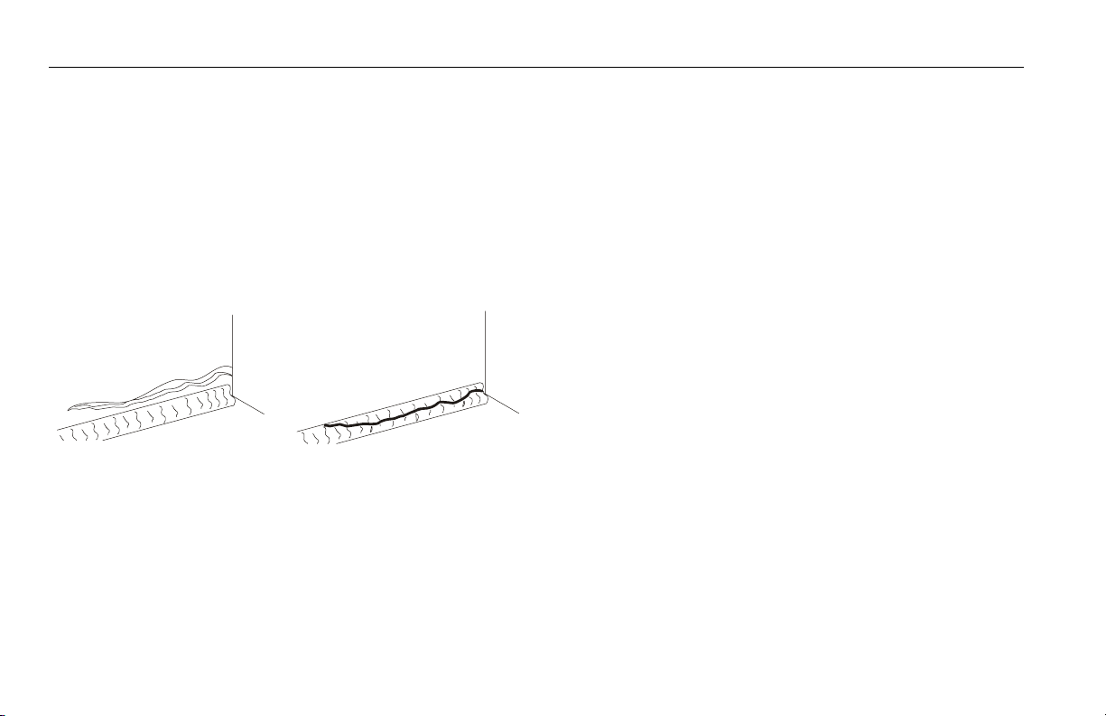
2. Structure - Inspect the machine structure for dents,
damage, weld or parent metal cracks or other discrepencies.
Pare nt Met al Cra ck
3. Decals and Placards – Check all for cleanliness and
legibility. Make sure none of the decals and placards are
missing. Make sure all illegible decals and placards are
cleaned or replaced.
Weld C rack
4. Operators and Safety Manuals – Make sure a copy of
the Operator and Safety Manual is enclosed in the
weather resistant storage container.
5. “Walk-Around” Inspection – Refer to Figure 2-2., Walk -
Around Inspection Diagram.
6. Battery – Charge as required.
7. Fuel - (Combustion Engine Powered Machines) – Add
the proper fuel as necessary.
8. Engine Oil Supply - Ensure that the engine oil level is at
the full mark on the dipstick and the filler cap is secure
9. Fluid Levels - Be sure to check the engine oil and the
hydraulic oil levels.
10. Accessories/Attachments - Reference the Operator
and Safety Manual of each attachment or accessory
installed upon the machine for specific inspection, operation, and maintenance instructions.
11. Function Check – Once the “Walk-Around” Inspection
is complete, perform a functional check of all systems in
an area free of overhead and ground level obstructions.
Refer to Section 4 for more specific instructions on the
operation of each function.
2-4 – JLG Lift – 3121321
Page 27

SECTION 2 - USER RESPONSIBILITIES, MACHINE PREPARATION AND INSPECTION
IF THE MACHINE DOES NOT OPERATE PROPERLY, TURN OFF THE
MACHINE IMMEDIATELY! REPORT THE PROBLEM TO THE PROPER
MAINTENANCE PERSONNEL. DO NOT OPERATE THE MACHINE UNTIL
IT IS DECLARED SAFE FOR OPERATION.
Function Check
Perform the Function Check as follows:
1. From the ground control panel with no load in the plat-
form:
a. Check that all function control switches and locks
are in place.
b. Operate all functions and check all limiting and cut-
out switches (see Table 2-2, Cutout Switch Limits).
c. Check for proper lifting and lowering of the plat-
form.
d. If the platform extension is extended, check that the
extension retracts.
NOTE: Be sure the platform extension is retracted before lower-
ing.
e. Ensure that all machine functions are disabled
when the Emergency Stop Button is activated.
f. Check manual descent.
g. Check for proper lifting and lowering of the plat-
form.
2. From the platform control console:
a. Ensure that the control console is firmly secured in
the proper location.
b. Check that all guards protecting the switches locks
are in place.
c. Operate all functions.
d. Ensure that all machine functions are disabled
when the Emergency Stop Button is pushed in.
e. Ensure that all LED’s in the control box are working
properly.
f. Check that the platform extension extends and
retracts properly.
g. With the platform in the transport (stowed) position
and with outriggers not selected:
i. Drive the machine on a level grade and stop to
ensure the brakes hold
ii. To ensure proper operation of the tilt sensor, drive
the machine onto a tilt greater than tht preset 3°
and attempt to lift.
3121321 – JLG Lift – 2-5
Page 28

SECTION 2 - USER RESPONSIBILITIES, MACHINE PREPARATION AND INSPECTION
Limit Switches
Check that the following limit switches function properly by
attempting to exceed the preset limits.
1. Lowered Position Limit Switch - Outriggers cannot be
deployed beyond the height of 9.8 ft (3 m).
2. Limit Switches for Drive Mode:
a. High Drive Speed Limit Switch - High drive speed is
possible up to a platform height of 11.5 ft (3.5 m).
Once the platform exceeds this limit, only low drive
speed is possible.
b. Maximum Drive Height/Maximum Height without
Outriggers Limit Switch - The maximum allowable
drive height is 50 ft (15.2 m). The liftling function,
without outriggers deployed, is only permitted up to
a platform height of 50 ft (15.2 m) as well.
3. Tilt Switch - If the machine is exceeding a tilt angle of 3°,
the platform cannot be elevated beyond 11.5 ft (3.5 m),
or if driving while elevated, the drive function will be cut
out.
4. Maximum Height Switch - The Maximum Height Switch
cuts out the lift function once the platform reaches 66.6
ft (20.3 m). This maximum height is only achieved when
the outriggers are selected and deployed.
5. Outrigger Interlocks - These switches allow the machine
to be driven when all outriggers are completely
retracted. The switch also prevents the platform from
being raised until the machine is level.
Table 2-2. Cutout Switch Limits
Limit and Cutout Switch Limit
Lowered Position 9.8 ft (3 m)
High Drive Speed Cutout * 11.5 ft (3.5 m)
Maximum Drive Height /Maximum
Height without Out riggers*
Tilt * 3°
Maximum Height * 66.6 ft (20.3 m)
Outrigger Interlock drive cut out when outriggers activated;
NOTE: * - these limit switches have corresponding LED’s on
the platform control console (refer to Figure 3-5., Platform Control Console). See page 3-9 and 3-10 for LED
functionality.
50 ft (15.3 m)
lift cut out when not level
2-6 – JLG Lift – 3121321
Page 29

SECTION 2 - USER RESPONSIBILITIES, MACHINE PREPARATION AND INSPECTION
1. Lowered Position Limit Switch
2. High Drive Speed Limit Switch
1
2
4
3
3. Max Drive Height/Max Height with-
out Outriggers Limit Switch
4. Max Height Limit Switch
5. Tilt Sensor
6. Outrigger Interlocks (all 4 outriggers)
Figure 2-1. Limit Switch Locations
3121321 – JLG Lift – 2-7
Page 30

SECTION 2 - USER RESPONSIBILITIES, MACHINE PREPARATION AND INSPECTION
Figure 2-2. Walk - Around Inspection Diagram
2-8 – JLG Lift – 3121321
Page 31

SECTION 2 - USER RESPONSIBILITIES, MACHINE PREPARATION AND INSPECTION
G
l
O
utrigger - (right front) - See Note
enera
Begin the “Walk-Around Inspection” at Item 1, as noted on
the diagram. Continue to the right (counterclockwise
viewed from top) checking each item in sequence for the
conditions listed in the “Walk-Around Inspection Checklist.”
TO AVOID POSSIBLE INJURY, BE SURE MACHINE POWER IS “OFF”
DURING “WALK-AROUND INSPECTION.”
NOTICE
DO NOT OVERLOOK VISUAL INSPECTION OF CHASSIS UNDERSIDE.
CHECKING THIS AREA OFTEN RESULTS IN DISCOVERY OF CONDITIONS WHICH COULD CAUSE EXTENSIVE MACHINE DAMAGE.
NOTE: On each item, make sure there are no loose or missing
parts, that they are securely fastened, and that no visible damage exists in addition to any other criteria mentioned.
1. Steer Linkage - See Note.
2. Steer Cylinder - See Note
Figure 2-3. Walk - Around Inspection Points (Sheet 1)
3.
4. Wheel and Tire Assembly - Properly secured, no miss-
ing lug nuts. Refer to Section 6. Inspect wheels for
damage and corrosion.
5. Tie Rod and Spindle - (right front) - See Note
6. Lift Cylinder - See Note
7. Drive Hub, Right Rear - See Note
8. Fuel Tank - See Note
9. Drive Hub, Left Rear - See Note
10. Motor and Hydraulic Pump Assembly - Check engine
oil level. See Note
11. Hydraulic Reservoir - Recommended hydraulic fluid
level on level indicator on tank. Breather cap secure
and working.
12. Tie Rod and Spindle - (left front) - See Note
13. Scissor Arms and Sliding Wear Pads (Not Shown) -
See Note
3121321 – JLG Lift – 2-9
Page 32

SECTION 2 - USER RESPONSIBILITIES, MACHINE PREPARATION AND INSPECTION
14. Control Valve - (Not Shown) No unsupported wires or
hoses; no damaged or broken wires.
15. Ground Controls - Placard secure and legible, control
switches return to neutral position, emergency stop
switch functions properly.
Figure 2-4. Walk - Around Inspection Points (Sheet 2)
16. Platform Control Console - Placard secure and legi-
ble, control lever and switches return to neutral, trigger switch and emergency stop switch function
properly, operation and safety manual in storage box.
17. Platform/Handrail Installation (Not Shown) - See Note
2-10 – JLG Lift – 3121321
Page 33

SECTION 3 - MACHINE CONTROLS
SECTION 3. MACHINE CONTROLS
3.1 GENERAL
NOTICE
SINCE THE MANUFACTURER HAS NO DIRECT CONTROL OVER
MACHINE APPLICATION AND OPERATION, CONFORMANCE WITH
GOOD SAFETY PRACTICES IN THESE AREAS IT IS THE RESPONSIBILITY OF THE USER AND HIS OPERATING PERSONNEL.
This section provides the necessary information needed to
understand control functions. Included in this section are the
operating characteristics and limitations, and functions and
purposes of controls and indicators. It is important that the
user read and understand the proper procedures before
operating the machine. These procedures will aid in obtaining optimum service life and safe operation.
3.2 OPERATING CHARACTERISTICS AND LIMITATIONS
General
A thorough knowledge of the operating characteristics and
limitations of the machine is always the first requirement for
any user, regardless of user’s experience with similar types
of equipment.
Placards
Important points to remember during operation are provided
at the control stations by DANGER, WARNING, CAUTION,
IMPORTANT and INSTRUCTION placards. This information
is placed at various locations for the express purpose of
alerting personnel of potential hazards constituted by the
operating characteristics and load limitations of the machine.
See foreword for definitions of the above placards.
3121321 – JLG Lift – 3-1
Page 34

SECTION 3 - MACHINE CONTROLS
Capacities
Raising platform above the stowed position with or without
any load in platform, is based on the following criteria:
1. Machine is level and positioned on a firm supporting
surface.
2. Load is within manufacturer’s rated capacity.
3. All machine systems are functioning properly.
3.3 CONTROLS AND INDICATORS
Ground Control Stations
1
1. Engine Control
2. Main Terminal Box
3. Ground Control Console
Figure 3-1. Side Compartment Electrical Tray
2
3
3-2 – JLG Lift – 3121321
Page 35

DO NOT OPERATE FROM GROUND CONTROL STATION WITH PERSON-
2
NEL IN THE PLATFORM EXCEPT IN AN EMERGENCY.PERFORM AS
MANY PRE-OPERATIONAL CHECKS AND INSPECTIONS FROM THE
GROUND CONTROL STATION AS POSSIBLE.
SECTION 3 - MACHINE CONTROLS
ehbelectronics
ehbelectronics
4
4
Vertragshandler
1
Vertragshandler
or
Air
3
Start
2
3
Glow
Tem p .
Oil
Alt.
OK
Start
1. Start Assist 2. Engine Start 3. Hourmeter 4. Glow Plug LED
Figure 3-2. Engine Control
3121321 – JLG Lift – 3-3
1
Page 36

SECTION 3 - MACHINE CONTROLS
1. Start Assist - This push button is used to help assist
starting the machine in cold temperatures. (overrides 6
second crank limit of Engine Start Button)
2. Engine Start - A push button switch that, when
depressed, will start the engine. (crank time limited to 6
seconds before power supply required recycling)
3. Hourmeter - A meter used to measure the amount of
time the machine is in use.
4. Glow Plug LED - This Yellow LED is off under normal
operating conditions. The LED is illuminated when the
ignition is on and the temperature sensing requires preglow.
NOTE: Do not start machine when Glow Plug LED is illuminated.
Once the LED goes out, machine starting is permitted.
3-4 – JLG Lift – 3121321
Page 37

Main Terminal Box
5
SECTION 3 - MACHINE CONTROLS
R
+X
-X
+Y
-Y
E900057 A
Figure 3-3. Main Terminal Box
1
2
3
4
1. Tilt Right LED
2. Tilt Left LED
3. Tilt Front LED
4. Tilt Rear LED
5. Drive Cutout LED
3121321 – JLG Lift – 3-5
Page 38

SECTION 3 - MACHINE CONTROLS
NOTE: The following LED’s are part of the self leveling system
and illuminate as the machine self levels.
1. Tilt Right LED - This LED will illuminate any time the
machine is tilted to the right.
2. Tilt Left LED - This LED will illuminate any time the
machine is tilted to the left.
3. Tilt Front LED - This LED will illuminate any time the
machine is tilted toward the machine front.
4. Tilt Rear LED - This LED will illuminate any time the
machine is tilted toward the machine rear.
5. Drive Cutout LED - This LED is illuminated when the out-
riggers are used and the lift function is operated.
3-6 – JLG Lift – 3121321
Page 39

Ground Control Console
6
5
7
SECTION 3 - MACHINE CONTROLS
R
1. Platform/ Ground Select (Key Switch)
2. Engine Start Switch
3. Emergency Stop Button
4
3
4. Outrigger Select Switch
5. Platform Lift/Lower Switch
6. Deck Extend/Retract Switch
7. Glow Plug LED
2
E900034A
8
1
Figure 3-4. Ground Control Console
8. Battery Disconnect Switch
3121321 – JLG Lift – 3-7
Page 40

SECTION 3 - MACHINE CONTROLS
Ground Control Descriptions:
1. Platform/Ground Select - This three way keyswitch is
used to select between platform controls or ground controls. When in the center position, the machine is disabled.
2. Engine Start Switch - Toggle Switch used to start engine.
3. Emergency Stop Button - Button, when depressed, will
immediately shut the machine off. Cuts out all functions
except emergency platform lowering.
4. Outrigger Select Switch - Toggle Switch used to select if
outriggers auto leveling function is active or not.
5. Platform Lift/Lower Switch - Toggle switch used to raise
and lower platform.
6. Deck Extend/Retract Switch - Toggle switch used to
extend and retract platform deck extension.
NOTE: The platform deck extension should be retracted before
lowering the platform.
7. Glow Plug LED - This Yellow LED is off under normal
operating conditions. The LED is illuminated when the
ignition is on and the temperature sensing requires preglow.
NOTE: Do not start machine when Glow Plug LED is illuminated.
Once the LED goes out, machine starting is permitted.
8. Battery Disconnect Switch - Disconnects ground control
panel from the battery.
3-8 – JLG Lift – 3121321
Page 41

3.4 PLATFORM CONTROL CONSOLE
3
6
SECTION 3 - MACHINE CONTROLS
9
11
2
10
1
8
7
1. Engine Start Switch
2. Emergency Stop Button
E900036A
3. Deck Extension/Drive/Lift Select Switch
4. Drive Speed Switch
5. Lift/Drive/Deck/Steer Controller
6. Horn Button
7. Drive Enabled LED
8. Glow Plug Active or Enabled LED
9. Lift Enabled LED
10. High Drive Speed Enabled LED
11. Tilt LED
R
E900030C
4
5
Figure 3-5. Platform Control Console
3121321 – JLG Lift – 3-9
Page 42

SECTION 3 - MACHINE CONTROLS
Platform Control Descriptions:
When platform/ground control select switch is switched to
platform all movements and operations are controlled via the
platform control panel. The controls are activated through
either push-buttons or toggle switches, whose functions are
marked with symbols and / or written text.
1. Engine Start Switch - Toggle switch that turns the diesel
engine on and off. Up for on, down for off.
2. Emergency Stop Button - Button, when depressed, will
immediately shut the machine off. Cuts out all functions
except emergency platform lowering.
3. Deck Extension/Drive/Lift Select Switch - 3 position tog-
gle switch that selects the functions of platform extension, drive or lift. Up for platform extension, middle for
drive, and down for lift. Works in conjunction with the
joystick controller.
4. Drive Speed Switch - 3 position toggle switch that
selects between fast drive, slow drive or posi-traction.
Posi-traction evenly distributes the torque between all
four wheels to provide better traction in situations that
require it.
5. Lift/Drive/Deck/Steer Controller - The Controller works in
conjunction with the platform extension, drive and the lift
switch depending upon which function is selected. The
button on the front of the joystick is the enable trigger.
This trigger must be held in to work all joystick controlled functions. When the Drive function is selected,
moving the joystick forward and backwards operates
the forward and reverse movement of the machine. The
switch on top of the joystick controls the steering of the
machine when the Drive function is selected. When the
Deck function is selected, moving the joystick forward
and backward extends and retracts the platform deck
extension. When the Lift function is selected, moving
the joystick forward and backwards raises and lowers
the platform.
6. Horn - Button, when depressed, activates the horn.
7. Drive Enabled LED - This Green LED is illuminated when
drive is enabled. The LED goes out when the platform is
above the maximum drive height, or with outriggers
selected and deployed.
8. Glow Plug Enabled or Active LED - This Yellow LED is off
under normal operating conditions. The LED is illuminated when the ignition is on and the temperature sensing requires pre-glow.
NOTE: Do not start machine when Glow Plug LED is illuminated.
Once the LED goes out, machine starting is permitted.
3-10 – JLG Lift – 3121321
Page 43

9. Lift Enabled LED - This Green LED is illuminated when
the lift function is enabled. The light goes out when
tilted above 11.5 ft (3.5 m) or at maximum height 66.7 ft
(20.3 m) with the outriggers deployed, or 50 ft (15.3 m)
with the outriggers not deployed.
10. High Drive Speed Enabled LED - This Green LED is illu-
minated when high drive speed is enabled. The light
goes out when the platform is above the high drive
speed limit.
11. Tilt (slope) LED - This Red LED will illuminate when the
machine is driven on a slope greater than the allowable
3°. The LED remains off under normal operating conditions.
SECTION 3 - MACHINE CONTROLS
3121321 – JLG Lift – 3-11
Page 44

SECTION 3 - MACHINE CONTROLS
13
12
13
12
13
12
13
13
13
3
8
10
16
17
6
15
8
3
10
3
22
23
7
20
28
27
11
5
13
12
13
3
22
7
28
23
17
6
26
21
19
17
16
24
Figure 3-6. Decal Location (ANSI) - Sheet 1 of 2
3-12 – JLG Lift – 3121321
Page 45

SECTION 3 - MACHINE CONTROLS
3
3
22
7
3
8
10
31
16
17
8
10
22
7
3
16
6
23
26
17
23
4
14
9
32
Figure 3-7. Decal Location (ANSI) - Sheet 2 of 2
3121321 – JLG Lift – 3-13
Page 46

SECTION 3 - MACHINE CONTROLS
10
9
10
9
10
9
10
10
10
13
6
8
17
15
34
4
14
13
6
8
13
22
23
5
16
20
12
27
32
3
10
9
10
13
22
5
23
27
15
26
4
19
21
15
17
34
18
Figure 3-8. Decal Location (CSA) - Sheet 1 of 2
3-14 – JLG Lift – 3121321
Page 47

SECTION 3 - MACHINE CONTROLS
13
22
5
13
6
8
35
17
34
15
6
8
13
13
22
4
23
5
26
34
17
15
23
2
Figure 3-9. Decal Location (CSA) - Sheet 2 of 2
11
7
36
3121321 – JLG Lift – 3-15
Page 48

SECTION 3 - MACHINE CONTROLS
Table 3-1. Decal Legend
Table 3-1. Decal Legend
Item #
1-- --
2 -- 1701505
3 1701214 1701640
4 1701505 1702773
5 1701640 1703687
6 1702773 1703811
7 1703687 1703812
8 1703811 1703814
9 1703812 1703819
10 1703814 1704277
11 1703816 1704412
12 1703819 1704684
13 1704277 1704690
14 1704412 1704885
15 1704885 1705040
16 1705694 1705303
17 1705695 1705694
ANSI
(0275932-G)
CSA English/French
(1001092749-F)
Item #
18 -- 1001103745
19 1706482 1706482
20 1706485 1706485
21 1706487 1706487
22 1706559 1706559
23 1706560 1706560
24 1001103745 --
25 -- --
26 1707182 1707182
27 1707185 1707187
28 1707187 --
29 - 30 -- --
31 1703464 --
32 1706098 1001092736
33 -- --
34 -- 1705717
35 -- 1703464
36 -- 1706098
ANSI
(0275932-G)
CSA English/French
(1001092749-F)
3-16 – JLG Lift – 3121321
Page 49

SECTION 4 - MACHINE OPERATION
SECTION 4. MACHINE OPERATION
4.1 DESCRIPTION
General Description of the Functions and Components.
The normal location to operate the machine is on the platform. However, the platform control box can be disconnected from the platform location and plugged in (for
emergency use, and loading onto a transport vehicle) at the
distribution terminal inside the valve compartment of the
machine.
4.2 STARTING
Ensure Battery Disconnect Switch is not cutting off the battery power. On the Ground Control Console, select the operating position (platform vs. ground).
NOTE: If Glow Plug LED illuminates, wait until the LED goes out
before attempting to start the engine.
ENGINE EXPLOSION HAZARD. MACHINE IS EQUIPPED WITH A COLD
START AID. DO NOT USE ADDITIONAL ETHER. FAILURE TO COMPLY
COULD RESULT IN DEATH OR SERIOUS INJURY.
On the selected Operating Console, press the Engine Start
Switch up and hold to start the engine. Release the switch
once engine starts. On the ground control console, select
Outriggers active or disabled.
The Engine Start Switch can also be used to shut the engine
off when the switch is pressed down.
NOTE: The Start Button on the Engine Control box can also be
used to start the engine (refer to Figure 3-2.).
3121321 – JLG Lift – 4-1
Page 50

SECTION 4 - MACHINE OPERATION
4.3 LIFTING AND LOWERING
DO NOT RAISE PLATFORM EXCEPT ON A FIRM UNIFORM SURFACE
FREE OF OBSTRUCTIONS AND HOLES.
ENSURE SCISSOR ARM AREA IS FREE OF PERSONNEL PRIOR TO
LOWERING PLATFORM.
DO NOT LOWER THE PLATFORM WITHOUT COMPLETELY RETRACTING THE PLATFORM EXTENSION.
Lifting:
1. If operating from the ground control console:
a. Lift up on the Platform Lift/Lower Switch to achieve
desired elevation.
2. If operating from the platform control console:
a. Position the Drive/Lift Select Switch to the "Lift" posi-
tion. Press and hold the enable trigger on the front
of the joystick while moving the joystick forward to
raise the platform to desired elevation. Once the
trigger is released or the joystick is returned to the
neutral position, the movement will stop.
Lowering:
1. If operating from the ground control console:
a. Press down on the Platform Lift/Lower Switch to
achieve desired elevation.
2. If operating from the platform control console:
a. Position the Drive/Lift Select Switch to the "Lift" posi-
tion. Press and hold the enable trigger on the front
of the joystick while moving the joystick backward
to lower the platform to desired elevation. Once the
trigger is released or the joystick is returned to the
neutral position, the movement will stop.
NOTE: When the machine is in "Drive Mode," the lifting and low-
ering functions are deactivated. Manual descent is the
only allowable platform movement when in "Drive Mode."
The machine is equipped with gravity descent. The
engine does not need to be running to lower the platform.
4-2 – JLG Lift – 3121321
Page 51

4.4 AUTOMATIC SELF LEVELING CHASSIS
SECTION 4 - MACHINE OPERATION
The machine is equipped with an auto leveling feature that
allows the operator to automatically level the machine. When
the machine is leveled, the lift function is automatically
enabled. The indicator LED’s on the Main Terminal Box will
also indicate when the machine is level ( See Figure 3-3. on
page 3-4 and page 3-5 for an explanation of the LED’s). This
function can be turned on or off at the ground control station.
With the auto leveling function selected, the outriggers are
deployed by using the lift controller. Joystick forward will
extend the outriggers and Joystick back will retract the outriggers.
All outriggers must be extended and in contact with the support surface before the platform is lifted from the stowed
position. If one or more outriggers, despite being fully
extended, is not in contact with the supporting surface the
outriggers must be retracted and the machine moved to a
more appropriate position.
To retract the outriggers, activate the lowering function with
the joystick. When the platform is completely lowered, the
outriggers will begin to retract. Once all outriggers are completely retracted, the drive function will be enabled and the
Drive Enabled LED on the platform control console will illuminate.
IF THE MACHINE BECOMES UNLEVEL, CAREFULLY LOWER THE PLATFORM AND REPOSITION THE MACHINE.
NOTICE
ALWAYS BE SURE THAT THE OPERATING SURFACE THE MACHINE IS
TO BE USED ON IS FIRM AND FREE OF ANY VOIDS OR OBSTRUCTIONS
THAT MAY CAUSE THE OUTRIGGERS TO NOT PERFORM PROPERLY.
3121321 – JLG Lift – 4-3
Page 52

SECTION 4 - MACHINE OPERATION
4.5 DRIVING THE MACHINE FROM THE PLATFORM
To activate the drive of the machine, the controller (joystick)
has to be moved forward for forward-drive and back for
reverse-drive. The controller has a neutral zone of about ±
7% of the total possible moving distance. After reaching the
end of the neutral zone, the machine starts to move.
DO NOT DRIVE WITH PLATFORM RAISED EXCEPT ON A SMOOTH, FIRM
AND LEVEL SURFACE FREE OF OBSTRUCTIONS AND HOLES.
TO AVOID LOSS OF TRAVEL CONTROL OR UPSET ON GRADES AND SIDESLOPES, DO NOT DRIVE MACHINE ON GRADES OR SIDESLOPES
EXCEEDING THOSE SPECIFIED. REFERENCE FIGURE 4-1., GRADE AND
SIDESLOPE.
4-4 – JLG Lift – 3121321
Page 53

SECTION 4 - MACHINE OPERATION
E
D
A
R
G
S
I
D
E
S
L
O
P
E
HORIZONTAL
Figure 4-1. Grade and Sideslope
3121321 – JLG Lift – 4-5
Page 54

SECTION 4 - MACHINE OPERATION
4.6 STEERING
The steer function is operated by depressing the two positioned button on top of the joystick. Pressing and holding
the button to the right will turn the wheels to the right.
Release the button when desired direction is achieved.
When the button is released, the wheels will remain in the
turned position. To straighten and/or turn to the left, the button must be pushed and held in the opposite direction (left in
this case). The same procedure applies for straightening or
turning right when wheels are in left turn position.
4.7 HYDRAULIC PLATFORM EXTENSION
With the lift/drive/extension switch in the extension position,
the platform can be hydraulically extended.The function is
activated by moving the controller forward to extend and
backwards to retract.
4.8 EMERGENCY LOWERING - MANUAL DESCENT
All control switches have to be set to the neutral position.
Next, the emergency lowering valve, which is located on the
lifting ram, can be opened hydraulically by a hand pump
located inside the hydraulic compartment. Once the lowering
is completed all levers of the emergency lowering function
have to be put into the neutral position. Refer to Section 5.3,
Manual Procedures for instructions on manual descent.
4.9 PARKING AND STOWING
When machine use is completed, the machine has to be fully
lowered and the battery isolator switch should be turned off.
NOTICE
THE MACHINE SHOULD BE LOCKED BY THE KEYSWITCH ON THE
GROUND CONTROL PANEL TO AVOID THE USE BY ANY UNAUTHORIZED PERSONNEL.
In case the machine is not used for a longer period of time, the
batteries should be charged once every two weeks due to the
self discharge and power consumption of the machine at rest.
4-6 – JLG Lift – 3121321
Page 55

4.10 TIE DOWN/LIFT LUGS
Tie Down
When transporting the machine, the platform extension must
be fully retracted and the platform fully lowered in the stowed
position with the machine securely tied down to the truck or
trailer deck. Refer to the tie down lugs in Figure 4-2., Lifting
and Tie Down Points.
Lifting
If it becomes necessary to lift the machine, it is possible to
do so from the lifting lugs located at the four corners of the
machine. These lugs enable the machine to be lifted using
cranes or suitable lifting devices.
NOTE: If lifting becomes necessary from the lifting lugs, JLG
Industries Inc. recommends the use of a proper spreader
bar and straps/chains to avoid damage to the machine.
Cranes or other lifting devices must be capable of handling the weights listed in the Operating Specifications
table in section 6 of this manual.
Tie Down
SECTION 4 - MACHINE OPERATION
Tie Down
Lift Lugs
Figure 4-2. Lifting and Tie Down Points
3121321 – JLG Lift – 4-7
Page 56

SECTION 4 - MACHINE OPERATION
4.11 TRANSPORT AND STORAGE OF THE MACHINE
NOTICE
DURING TRANSPORT THE BATTERY DISCONNECT SWITCH SHOULD
BE DISCONNECTED.
R
E900034A
1
The control box must be unplugged during the transport of the
machine. The socket at the platform must be closed, whenever
the control box is not plugged in. This is the best way to prevent
any damages due to moisture and transport to the electrical
components of the machine.
• Ensure the control box is stored in a safe, dry location and
the main joystick controller is not affected by any harsh
forces.
1. Battery Disconnect Switch
4-8 – JLG Lift – 3121321
Page 57

SECTION 5 - EMERGENCY PROCEDURES
SECTION 5. EMERGENCY PROCEDURES
5.1 GENERAL
This section provides information on the procedures to be
followed and on the systems and controls to be used in the
event an emergency situation is encountered during
machine operation. Prior to operation of the machine and
periodically thereafter, the entire operating manual, including
this section, should be reviewed by all personnel whose
responsibilities include any work or contact with the
machine.
Emergency Stop Switch
These large red buttons, one located outside the valve compartment and one at the Platform Control Station, will immediately stop the machine when depressed.
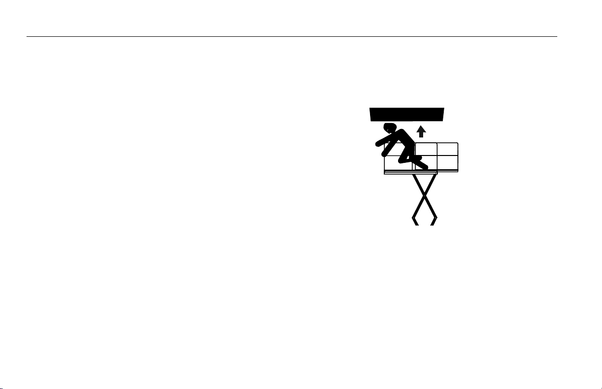
Platform Caught Overhead
If the platform becomes jammed or snagged in overhead
structures or equipment, do not continue operation of the
machine from either the platform or the ground until the
operator and all personnel are safely moved to a secure
location. Only then should an attempt be made to free the
platform using any necessary equipment and personnel. Do
not operate controls to cause one or more wheels to leave
the ground.
Righting of Tipped Machine
A forktruck of suitable capacity or equivalent equipment
should be placed under the elevated side of the chassis, with
a crane or other suitable lifting equipment used to lift the
platform while the chassis is lowered by the forklift or other
equipment.
Post-Incident Inspection
Following any incident, thoroughly inspect the machine and
test all functions first from the ground controls, then from the
platform controls. Do not lift above 10 ft (3 m) until you are
sure that all damage has been repaired, and that all controls
are operating correctly.
3121321 – JLG Lift – 5-1
Page 58

SECTION 5 - EMERGENCY PROCEDURES
5.2 EMERGENCY OPERATION
Use of Ground Controls
NOTICE
KNOW HOW TO USE THE GROUND CONTROLS IN AN EMERGENCY SITUATION.
Ground personnel must be thoroughly familiar with the
machine operating characteristics and the ground control
functions. Training should include operation of the machine,
review and understanding of this section and hands-on operation of the controls in simulated emergencies.
Operator Unable to Control Machine
1. Operate the machine from ground controls ONLY with
the assistance of other personnel and equipment
(cranes, overhead hoists, etc.) as may be required to
safely remove the danger or emergency condition.
2. Other qualified personnel on the platform may use the
platform controls. DO NOT CONTINUE OPERATION IF
CONTROLS DO NOT FUNCTION NORMALLY.
3. Cranes, forklift trucks or other equipment, which may be
available, are to be used to stabilize motion of the
machine in case machine controls are inadequate or
malfunction when used prior to removing platform occupants.
Incident Notification
It is imperative that JLG Industries, Inc. be notified immediately of any incident involving a JLG product. Even if no
injury or property damage is evident, JLG should be contacted by telephone and provided with all necessary details
at:
877-554-7233 or 240-420-2661
It should be noted that failure to notify the Manufacturer of an
incident involving a JLG Industries product within 48 hours of
such an occurrence may void any warranty consideration on
that particular machine.
5-2 – JLG Lift – 3121321
Page 59

SECTION 5 - EMERGENCY PROCEDURES
5.3 MANUAL PROCEDURES
Manual Platform Deck Retraction
NOTE: The platform deck extension should be retracted before
the platform lowering begins.
1. Locate the valve block and hand pump inside the
hydraulic cover on the right side of the machine.
2. Turn valve knob on the manual hand pump clockwise
until tight.
3. Locate the middle valve handle on the small valve bank
as shown and pull down to engage.
NOTE: Step 3 applies only to machines prior to S/N 1200021189.
NOTE: Step 2 applies only to machines prior to S/N 1200021189.
3121321 – JLG Lift – 5-3
Page 60

SECTION 5 - EMERGENCY PROCEDURES
4. Locate separate valve handle in the storage bag and
place on the push cylinder valve of the main hydraulic
block. (1
NOTE: Valve handles are located in plastic storage bag within
valve compartment.
5. Open valve by pulling handle down.
st
section from the left).
6. While continuing to hold the valve open, activate the
manual hand pump by pumping back and forth until the
deck extension is fully retracted.
7. After manual platform deck retraction is complete,
release valve on the valve bank and remove handle from
valve. Return the valve handle on the small valve bank
back to it’s original position (if applicable). Turn the
valve on the manual hand pump counterclockwise until
fully open (if applicable). Push pump handle forward.
8. Remove handle and place back into storage bag.
5-4 – JLG Lift – 3121321
Page 61

SECTION 5 - EMERGENCY PROCEDURES
Manual Platform Lowering (Prior to S/N
1200021189)
NOTE: The manual descent system is provided as an emergency
means to lower personnel from the platform.
1. Locate the valve block and hand pump inside the
hydraulic cover on the right side of the machine.
2. Turn valve knob on the manual hand pump clockwise
until tight.
3. Locate the valve handle on the left side of the small
valve bank, as shown below, and pull down to engage.
4. Activate the manual hand pump by pumping back and
forth.
PLATFORM WILL CONTINUE TO DESCEND ONCE MOVEMENT IS
STARTED. TO STOP PLATFORM DESCENT, TURN VALVE KNOB COUNTERCLOCKWISE.
5. After manual lowering is complete, release valve on the
valve bank and remove handle from valve. Return the
valve handle on the small valve bank back to it’s original
position (if applicable). Turn the valve on the manual
hand pump counterclockwise until fully open (if applicable). Push pump handle forward.
3121321 – JLG Lift – 5-5
Page 62

SECTION 5 - EMERGENCY PROCEDURES
Manual Platform Lowering (S/N 1200021189 to Present)
NOTE: The manual descent system is provided as an emergency
means to lower personnel from the platform.
1. Locate the valve block and manual hand pump inside
the hydraulic cover on the right side of the machine.
1
2
1. Main Valve Block 2. Manual Hand Pump
2. Place the handle on the second section of the main
valve block (3) as shown and pull down to engage.
3
NOTE: Valve handles are located in plastic storage bag within
valve compartment.
3. Activate the manual hand pump by pumping back and
forth (2).
2
5-6 – JLG Lift – 3121321
Page 63

PLATFORM WILL CONTINUE TO DESCEND ONCE MOVEMENT IS
STARTED. TO STOP PLATFORM DESCENT, RELEASE THE HANDLE ON
THE MAIN VALVE BLOCK
4. After manual deck retraction is complete, release the
handle on the main valve block.
SECTION 5 - EMERGENCY PROCEDURES
5.4 EMERGENCY TOWING
RUNAWAY VEHICLE/MACHINE HAZARD. MACHINE HAS NO TOWING
BRAKES. TOWING VEHICLE MUST BE ABLE TO CONTROL MACHINE AT
ALL TIMES. ON-HIGHWAY TOWING NOT PERMITTED. FAILURE TO FOLLOW INSTRUCTIONS COULD CAUSE SERIOUS INJURY OR DEATH.
MAXIMUM TOWING SPEED 5 M.P.H. (8 K.M.H.) FOR NO LONGER THAN
30-45 MINUTES.
MAXIMUM TOWING GRADE 25%.
Prior to Towing
Prior to towing the machine, complete the following:
DO NOT TOW MACHINE WITH ENGINE OPERATING OR DRIVE HUBS
ENGAGED.
1. Completely lower platform.
2. Disconnect drive hubs by inverting disconnect cap.
(See Figure 5-1.) After towing the machine, complete the
following:
3121321 – JLG Lift – 5-7
Page 64

SECTION 5 - EMERGENCY PROCEDURES
a. Reconnect drive hubs by inverting disconnect cap.
(See Figure 5-1.)
1
3
1. Hub Connected
2. Disconnect Cap
3. Hub Disconnected
2
Figure 5-1. Drive Disconnect Hub
5-8 – JLG Lift – 3121321
Page 65

SECTION 6 - GENERAL SPECIFICATIONS AND OPERATOR MAINTENANCE
SECTION 6. GENERAL SPECIFICATIONS AND OPERATOR MAINTENANCE
6.1 INTRODUCTION
This section of the manual provides additional necessary
information to the operator for proper operation and maintenance of this machine.
The maintenance portion of this section is intended as information to assist the machine operator to perform daily maintenance tasks only, and does not replace the more thorough
Preventive Maintenance and Inspection Schedule included
in the Service and Maintenance Manual.
Other Publications Available Specific to this Machine:
Service and Maintenance Manual ..................... 3121322
Illustrated Parts Manual ..................................... 3121323
3121321 – JLG Lift – 6-1
Page 66

SECTION 6 - GENERAL SPECIFICATIONS AND OPERATOR MAINTENANCE
6.2 OPERATING SPECIFICATIONS
Table 6-1. Operating Specifications
Maximum Working Height:
with outriggers deployed
with outriggers stowed
Maximum Platfor m Height :
with outriggers deployed
with outriggers stowed
Turning Radius (Outside)
Maximum Work Load (Capacity) - Main Platform/
Platform Extension
Maximum Number of Persons 4
Tools and Equipment
Main Platform / Platform Extension
Maximum Horizontal Manual Side Force
Tilt Sensor Setting 3°
Maximum Operating Wind Speed
Gross Machine Weight (Approximate)
73.2 ft (22.3 m)
56.8 ft (17.3 m)
66.7 ft (20.3 m)
50 ft (15.3 m)
1650 lbs/1100 lbs
(750 kg/500 kg)
1300 lbs/397 lbs
(430 kg/180 kg)
200 Lb force
(12.5 m/s)
25,132 lbs
(11,400 kg)
14.8 ft
(4.5 m)
(890N)
28 mph
Table 6-1. Operating Specifications
Drive Speed (slow)
Drive Speed (fast)
Lift Speed (Platform Empty) 60 sec
Lowering Speed 60 sec
Sideslope (Machine Stowed) 5°
Gradeability (Machine Stowed) 25%
Maximum Operating Hydraulic Pressure
Power Supply Diesel Engine
Maximum Ground Bearing Pressure:
Outrigger Pads
Tires
Maximum Tire Load
Maximum Outrigger Pad Load
Electrical System Voltage 24 V
Ground Clearance
0.4 mph (0.6 ft/sec)
(0.2 m/s)
2.2 mph (3.2 ft/sec)
(1 m/s))
3046 psi
(210 bar)
128 psi (9 kg/cm²)
71 psi (5 kg/cm²)
9700 lbs
(4400 kg)
9548 lbs
(4290 kg)
0.9 ft
(0.27 m)
6-2 – JLG Lift – 3121321
Page 67

SECTION 6 - GENERAL SPECIFICATIONS AND OPERATOR MAINTENANCE
Dimensional Data Capacities
Table 6-2. Dimensional Data
Tr ans po r t H ei gh t
(rails up / rails down)
Platform dimensions - extension retracted
Platform dimensions - extension extended
Transport Dimensions
12.5 ft / 9.9 ft
(3.8 m /3m)
15 x 7.9 ft
(4.6 x 2.4 m)
24.3 x 7.9 ft
(7.4 x 2.4 m)
15.9 x 7.9 ft
(4.8 x 2.4m)
Tires
Table 6-3. Capacities
Fuel Tank 23.8 gal (90 L)
Hydraulic Tank 35.7 gal (135 L)
Engine Crankcase
w it h F il t er
without Filter
11 qt (10.5 L)
10.6 qt (10 L)
Table 6-4. Tire Specifications
Size
Ply Rating
Load Range
Tire Inflation
(Foam Fill)
Max Tire Load
355/55D625
14
G
90 psi
(6.2 bar)
9700 lbs
(4400 kg)
3121321 – JLG Lift – 6-3
Page 68

SECTION 6 - GENERAL SPECIFICATIONS AND OPERATOR MAINTENANCE
Engine Component Weights
Table 6-5. Engine Specifications
Type Deutz F3L 2011 Deutz D2011 L03i
Number of Cylinders 3
Displacement
Bore 3.7 in (94 mm)
Stroke 4.4 in (112 mm)
Fuel Type Diesel
Table 6-6. Engine Battery Specifications
Voltage 12V
Cranking Performance 100
Reserve Capacity 880
140.4 in
3
(2.3L)
2331 cm³
Table 6-7. Component Weights
Fixed Platform 1,874 lb (850 kg)
Chassis with Foam Filled Tires 8,378 lb (3,800 kg)
Arm Assembly 11,244 lb (5,100 kg)
Lift Cylinder 992 lbs (450 kg)
6-4 – JLG Lift – 3121321
Page 69

SECTION 6 - GENERAL SPECIFICATIONS AND OPERATOR MAINTENANCE
AMBIENT AIR
TEMPERATURE
NO OPERATION ABOVE THIS
AMBIENT TEMPERATURE
120°F (49°C)
110°F (43°C)
100°F (38°C)
90°F (32°C)
SAE 20W-50
80°F (27°C)
70°F (21°C)
60°F (16°C)
50°F (10°C)
ENGINE
SPECIFICATIONS
SUMMER
GRADE
FUEL
SAE OW-30
SAE 5W-30
SAE OW-40
SAE 5W-40
SAE 10W-30
SAE 10W-40
SAE 15W-40
40°F (4°C)
30°F (-1°C)
ENGINE WILL START AND OPERATE UNAIDED AT THIS
TEMPERATURE WITH THE RECOMMENDED FLUIDS AND A
FULLY CHARGED BATTERY
ENGINE WILL START AND OPERATE AT THIS TEMPERATURE
WITH THE RECOMMENDED FLUIDS, A FULLY CHARGED BATTERY
AND THE AID OF A COMPLETE JLG SPECIFI ED COLD WEATHER
PACKAGE (IE. ENGINE BLOCK HEATER, ETHER INJECTION OR GLOW
PLUGS, BATTERY WARMER AND HYDRAULIC OIL TANK HEATER)
NO OPERATION BELOW THIS
AMBIENT TEMPERATURE
4150548 C
WINTER
GRADE
FUEL
WINTER
GRADE
FUEL
WITH
KEROSENE
ADDED
20°F (-7°C)
10°F (-12°C)
0°F (-18°C)
-10°F (-23°C)
-20°F (-29°C)
-30°F (-34°C)
-40°F (-40°C)
Figure 6-1. Engine Operating Temperature Specifications - Sheet 1 of 2
3121321 – JLG Lift – 6-5
Page 70

SECTION 6 - GENERAL SPECIFICATIONS AND OPERATOR MAINTENANCE
E
EXTENDED DRIVING WITH
HYDRAULIC OIL TANK
TEMPERATURES OF 180°F
(82°C) OR ABOVE
IF EITHER OR BOTH CONDITIONS
EXIST JLG HIGHLY RECOMMENDS
THE ADDITION OF A HYDRAULIC
OIL COOLER (CONSULT JLG SERVICE)
AMBIENT AIR
TEMPERATURE
180°F (82°C)
(HYD. OIL TANK TEMP.
120°F (49°C)
110°F (43°C)
100°F (38°C)
90°F (32°C)
NO OPERATION ABOVE THIS
AMBIENT TEMPERATURE
PROLONGED OPERATION IN
AMBIENT AIR TEMPERATURES
OF 100°F (38°C) OR ABOVE
NOTE:
1) RECOMMENDATIONS ARE FOR AMBIENT TEMPERATURES
CONSISTANTLY WITHIN SHOWN LIMITS
2) ALL VALUES ARE ASSUMED TO BE AT SEA LEVEL
80°F (27°C)
70°F (21°C)
60°F (16°C)
50°F (10°C)
40°F (4°C)
30°F (-1°C)
20°F (-7°C)
10°F (-12°C)
0°F (-18°C)
-10°F (-23°C)
-20°F (-29°C)
-30°F (-34°C)
-40°F (-40°C)
MOBIL
DTE 13
MOBIL 424 10W-30
EXXON UNIVIS HVI 26
NO OPERATION BELOW THIS
AMBIENT TEMPERATURE
DO NOT START UP HYDRAULIC SYSTEM
WITHOUT HEATING AIDS WITH MOBILE 424
HYDRAULIC OIL BELOW THIS TEMPERATURE
DO NOT START UP HYDRAULIC SYSTEM
WITHOUT HEATING AIDS AND COLD WEATHER
HYDRAULIC OIL BELOW THIS TEMPERATURE
HYDRAULIC
SPECIFICATIONS
°F °C
+32 0
+23 -5
+14 -10
+5 -15
-4 -20
-13 -25
AMBIENT TEMPERATURE
-22 -30
0 10 20 30 40 5 0 60
% OF ADDED KEROSENE
SUMMER - GRADE
FUEL
WINTER - GRAD
FUEL
Figure 6-2. Engine Operating Temperature Specifications - Sheet 2 of 2
6-6 – JLG Lift – 3121321
Page 71

SECTION 6 - GENERAL SPECIFICATIONS AND OPERATOR MAINTENANCE
Lubrication
Hydraulic Oil
Table 6-8. Hydraulic Oil
HYDRAULIC SYSTEM OPERATING
TEMPERATURE RANGE
0° to +23°F
(-18° to -5°C)
0° to +210°F
(-18° to +100°C)
+50° to +210°F
(+10° to +100°C)
NOTE: Hydraulic oils must have anti-wear qualities at least to API
Service Classification GL-3, and sufficient chemical stability for mobile hydraulic system service. JLG Industries
recommends Mobilfluid 424 hydraulic oil, which has an
SAE viscosity index of 152.
NOTE: When temperatures remain below 20°F (-7°C), JLG Indus-
tries recommends the use of Mobil DTE13.
SAE VISCOSITY GRADE
10W
10W-20, 10W-30
20W-20
NOTE: Aside from JLG recommendations, it is not advisable to
mix oils of different brands or types, as they may not contain the same required additives or be of comparable viscosities. If use of hydraulic oil other than Mobilfluid 424 is
desired, contact JLG Industries for proper recommendations.
Lubrication Specifications
Table 6-9. Lubrication Specifications
KEY SPECIFICATIONS
Multipurpose Grease having a minimum dripping
MPG
EPGL
EO
HO
point of 350°F (177°C). Excellent water resistance
and adhesive qualities, and being of extreme pres-
sure type. (Timken OK 40 pounds minimum.)
Extreme Pressure Gear Lube (oil) meeting API ser-
v ic e c la ss i fi ca ti o n G L-5 or M IL- Sp ec MI L- L-2 10 5.
Engine (crankcase) Oil. Gas - API SF/SG class, MIL-
L-2104. Diesel - API CC/CD class, MIL-L-2104B/
MIL-L- 21 04 C.
Hydraulic Oil. API service classification GL-3, e.g.
Mobil 424.
3121321 – JLG Lift – 6-7
Page 72

SECTION 6 - GENERAL SPECIFICATIONS AND OPERATOR MAINTENANCE
6.3 OPERATOR MAINTENANCE
1. Arm Pins
2. Outrigger Cylinders
3. Tie Rod End
4. Spindles
5. Engine Compartment
(Opposite Side)
6. Fuel Tank (Opposite
Side)
Figure 6-3. Operator Maintenance and Lubrication Diagram
6-8 – JLG Lift – 3121321
Page 73

SECTION 6 - GENERAL SPECIFICATIONS AND OPERATOR MAINTENANCE
NOTE: The following numbers correspond with those in Figure 6-
3., Operator Maintenance and Lubrication Diagram.
NOTE: Be sure to grease all like items on the opposite side of
machine.
1. Arm Pin
• Lube Points - 36 Grease Fittings
• Capacity - As Required
•Lube - MPG
• Interval - As Required
2. Outrigger Cylinders
• Lube Points - 4 Grease Fittings
• Capacity - As Required
•Lube - MPG
• Interval - As Required
3121321 – JLG Lift – 6-9
Page 74

SECTION 6 - GENERAL SPECIFICATIONS AND OPERATOR MAINTENANCE
3. Tie Rod End
• Lube Points - 2 Grease Fittings
• Capacity - As Required
•Lube -MPG
• Interval - As Required
4. Spindles
• Lube Points - 2 Grease Fittings
• Capacity - As Required
•Lube - MPG
• Interval - As Required
6-10 – JLG Lift – 3121321
Page 75

SECTION 6 - GENERAL SPECIFICATIONS AND OPERATOR MAINTENANCE
5. Engine Compartment
a. Engine Oil Check/Fill
• Lube Points - Fill Cap and Dip Stick
• Capacity - See Engine Manual
•Lube - EO SAE 20W20
• Interval - Every 3 months or 150 hours of operation
b. Air Filter
• Lube Points - Replaceable Element
• Interval - Every 6 months or 300 hours of operation
3121321 – JLG Lift – 6-11
Page 76

SECTION 6 - GENERAL SPECIFICATIONS AND OPERATOR MAINTENANCE
c. Hydraulic Oil Check/Fill
• Lube Points - Fill Cap and Site Gage
• Capacity - 68.7 gal (260 L)
•Lube - HO
• Interval - Check oil daily, change every 1200 hours of
operation
6. Fuel Tank
• Capacity - 90 L (23.8 gal)
• Lube - Diesel Fuel
• Interval - Check fuel periodically during each use
6-12 – JLG Lift – 3121321
Page 77

SECTION 6 - GENERAL SPECIFICATIONS AND OPERATOR MAINTENANCE
6.4 TIRES AND WHEELS
Tire Damage
For pneumatic tires, JLG Industries, Inc. recommends that
when any cut, rip, or tear is discovered that exposes sidewall
or tread area cords in the tire, measures must be taken to
remove the JLG product from service immediately. Arrangements must be made for replacement of the tire or tire
assembly.
For polyurethane foam filled tires, JLG Industries, Inc. recommends that when any of the conditions listed below are discovered, measures must be taken to remove the JLG
product from service immediately and arrangements must
be made for replacement of the tire or tire assembly.
• a smooth, even cut through the cord plies which
exceeds 3 inches (7.5 cm) in total length
• any tears or rips (ragged edges) in the cord plies
which exceeds 1 inch (2.5 cm) in any direction
• any punctures which exceed 1 inch (2.5cm) in diameter
• any damage to the bead area cords of the tire
If a tire is damaged but is within the above noted criteria, the
tire must be inspected on a daily basis to insure the damage
has not propagated beyond the allowable criteria.
Tire Replacement
JLG recommends a replacement tire be the same size, ply
and brand as originally installed on the machine. lease refer
to the JLG Parts Manual for the part number of the approved
tires for a particular machine and model. If not using a JLG
approved replacement tire, it is recommended that replacement tires have the following characteristics:
• Equal or greater ply/load rating and size of original.
• Tire tread contact width equal or greater than original.
• Wheel diameter, width, and offset dimensions equal to
the original.
Unless specifically approved by JLG Industries Inc. do not
replace a foam filled tire assembly with a pneumatic tire.
When selecting and installing a replacement tire, ensure that
all tires are inflated to the pressure recommended by JLG.
Due to size variations between tire brands, both tires on the
same axle should be the same.
3121321 – JLG Lift – 6-13
Page 78

SECTION 6 - GENERAL SPECIFICATIONS AND OPERATOR MAINTENANCE
Wheel Replacement
The rims installed on each product model have been
designed for stability requirements which consist of track
width, tire pressure, and load capacity. Size changes such as
rim width, center piece location, larger or smaller diameter,
etc., without written factory recommendations, may result in
an unsafe condition regarding stability.
Wheel Installation
It is extremely important to apply and maintain proper wheel
mounting torque.
WHEEL NUTS MUST BE INSTALLED AND MAINTAINED AT THE PROPER
TORQUE TO PREVENT LOOSE WHEELS, BROKEN STUDS, AND POSSIBLE DANGEROUS SEPARATION OF WHEEL FROM THE AXLE. BE SURE
TO USE ONLY THE NUTS MATCHED TO THE CONE ANGLE OF THE
WHEEL.
Tighten the lug nuts to the proper torque to prevent wheels
from coming loose. Use a torque wrench to tighten the fasteners. If you do not have a torque wrench, tighten the fasteners with a lug wrench, then immediately have a service
garage or dealer tighten the lug nuts to the proper torque.
Over-tightening will result in breaking the studs or perma-
nently deforming the mounting stud holes in the wheels. The
proper procedure for attaching wheels is as follows:
1. Start all nuts by hand to prevent cross threading. DO
NOT use a lubricant on threads or nuts.
2. Tighten nuts in the following sequence:.
1
6
3
5
4
2
6 L UG PATT ER N
6-14 – JLG Lift – 3121321
Page 79

SECTION 6 - GENERAL SPECIFICATIONS AND OPERATOR MAINTENANCE
3. The tightening of the nuts should be done in stages. Fol-
lowing the recommended sequence, tighten the nuts
per wheel torque chart.
TORQUE SEQUENCE
1st Stage 2nd Stage 3rd Stage
150-190 ft lbs
(210 - 270 Nm)
4. Wheel nuts should be torqued after the first 50 hours of
operation and after each wheel removal. Check torque
every 3 months or 150 hours of operation.
230 - 270 ft lbs
(320-380 Nm)
305 - 343 ft lbs
( 440 - 480 Nm)
3121321 – JLG Lift – 6-15
Page 80

SECTION 6 - GENERAL SPECIFICATIONS AND OPERATOR MAINTENANCE
NOTES:
6-16 – JLG Lift – 3121321
Page 81

SECTION 7 - INSPECTION AND REPAIR LOG
SECTION 7. INSPECTION AND REPAIR LOG
Table 7-1. Inspection and Repair Log
Date Comments
3121321 – JLG Lift – 7-1
Page 82

SECTION 7 - INSPECTION AND REPAIR LOG
Table 7-1. Inspection and Repair Log
Date Comments
7-2 – JLG Lift – 3121321
Page 83

TRANSFER OF OWNERSHIP
Thank You,
Product Safety & Reliability Department
JLG Industries, Inc.
13224 Fountainhead Plaza
Hagerstown, MD 21742
USA
Telephone: +1-717-485-6591
Fax: +1-301-745-3713
) ____________________
) ____________________
__________________________________________________
ownership of all JLG products. JLG maintains owner information for each JLG product
Please use this form to provide JLG with updated information with regard to the
and uses this information in cases where owner notification is necessary.
current ownership of JLG products. Please return completed form to the JLG Product
Safety & Reliability Department via facsimile or mail to address as specified below.
NOTE: Leased or rented units should not be included on this form.
Mfg. Model: _____________
Serial Number: ____________________________________________________________
Previous Owner: ___________________________________________________________
Address: _________________________________________________________________
_________________________________________________________________________
Country: _________________________ Telephone: (_______
Date of Transfer: _________________________________
If you now own but ARE NOT the original purchaser of the product covered by this
An Oshkosh Corporation Company
To Product Owner:
manual, we would like to know who you are. For the purpose of receiving safety-related
bulletins, it is very important to keep JLG Industries, Inc. updated with the current
Current Owner: ____________________________________________________________
__________________________________________________
_________________________________________________________________________
Address: _______________
Country: _________________________ Telephone: (_______
Who in your organization should we notify?
Name: ___________________________________________________________________
Title:____________________________________________________________________
Page 84

Page 85

Page 86

Corporate Office
JLG Industries, Inc.
1 JLG Drive
McConnellsburg PA. 17233-9533
USA
JLG Worldwide Locations
JLG Industries (Australia)
P.O. Box 5119
11 Bolwarra Road
Por t Macq ua rie
N.S.W. 2444
Australia
+61 2 65 811111
+61 2 65 810122
JLG Deutschland GmbH
Max-Planck-Str. 21
D - 27721 Ritterhude - Ihlpohl
Germany
+49 (0)421 69 350 20
+49 (0)421 69 350 45
JLG Polska
UI. Krolewska
00-060 Warsawa
Poland
+48 (0)914 320 245
+48 (0)914 358 200
JLG Latino Americana Ltda.
Rua Eng. Carlos Stevenson,
80-Suite 71
13092-310 Campinas-SP
Brazil
+55 19 3295 0407
+55 19 3295 1025
JLG Equipment Services Ltd.
Rm 1107 Landmark North
39 Lung Sum Avenue
Sheung Shui N. T.
Hong Kong
(852) 2639 5783
(852) 2639 5797
JLG Industries (Scotland)
Wright Business Centre
1 Lonmay Road
Queenslie, Glasgow G33 4EL
Scotland
+44 (0)141 781 6700
+44 (0)141 773 1907
(717) 485-5161
(717) 485-6417
JLG Industries (UK) Ltd
Bentley House
Bentley Avenue
Middleton
Greater Manchester
M24 2GP - England
+44 (0)161 654 1000
+44 (0)161 654 1001
JLG Industries (Italia) s.r.l.
Via Po. 22
20010 Pregnana Milanese - MI
Italy
+39 029 359 5210
+39 029 359 5845
Plataformas Elevadoras
JLG Iberica, S.L.
Trapadella, 2
P.I. Castellbisbal Sur
08755 Castellbisbal, Barcelona
Spain
+34 93 772 4700
+34 93 771 1762
3121321
JLG France SAS
Z.I. de Baulieu
47400 Fauillet
France
+33 (0)5 53 88 31 70
+33 (0)5 53 88 31 79
JLG Europe B.V.
Polaris Avenue 63
2132 JH Hoofddorp
The Netherlands
+31 (0)23 565 5665
+31 (0)23 557 2493
JLG Sverige AB
Enkopingsvagen 150
Box 704
SE - 176 27 Jarfalla
Sweden
+46 (0)850 659 500
+46 (0)850 659 534
www.jlg.com
 Loading...