

Page 1
Operation and Safety Manual
Keep this manual with the machine at all times.
Boom Lift Models
601S
ANSI
®
3121218
June 22, 2006
Page 2
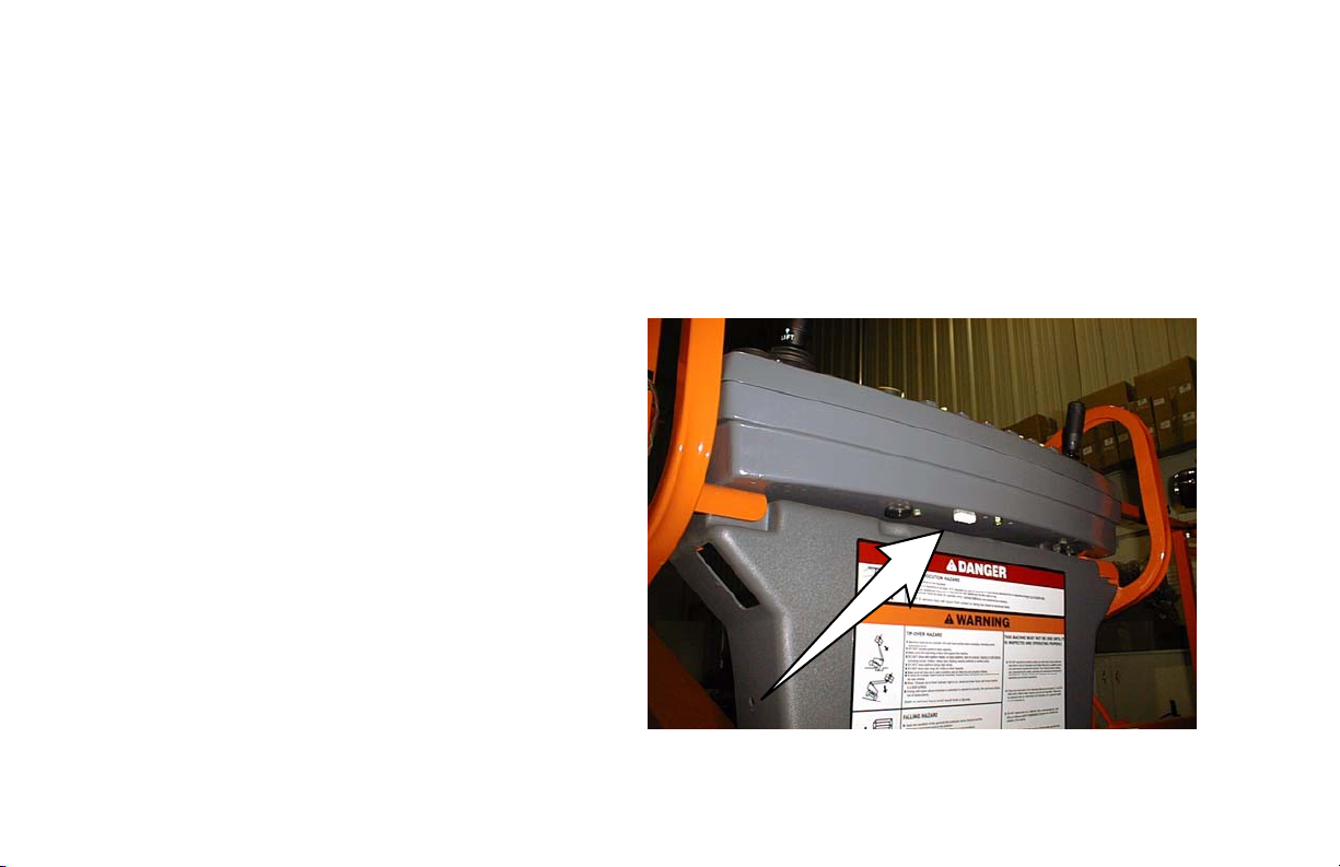
ADE Identification
All machines after S/N 60444 incorporate ADE (Advanced Design Electronics). The following machine
serial numbers prior to S/N 60444 also utilize ADE: 58993, 58998, 59222, 59223, 59275, 59281, 59315,
59319, 59352, 59358, 59361, 59769, 60253, 60254, 60286, and 60242.
A Machine that incorporates ADE (JLG Control System) can be outwardly identified by
the analyzer connection at the base of the
platform control box as shown by the arrow.
Page 3

FOREWORD
FOREWORD
This manual is a very important tool! Keep it with the machine at all times.
The purpose of this manual is to provide owners, users, operators, lessors, and lessees with the precautions and
operating procedures essential for the safe and proper machine operation for its intended purpose.
Due to continuous product improvements, JLG Industries, Inc. reserves the right to make specification changes
without prior notification. Contact JLG Industries, Inc. for updated information.
3121218 – JLG Lift – a
Page 4
FOREWORD
SAFETY ALERT SYMBOLS AND SAFETY SIGNAL WORDS
This is the Safety Alert Symbol. It is used to alert you to the potential personal
injury hazards. Obey all safety messages that follow this symbol to avoid possible
injury or death
INDICATES AN IMMINENTLY HAZARDOUS SITUATION. IF NOT
AVOIDED, WILL RESULT IN SERIOUS INJURY OR DEATH. THIS DECAL
WILL HAVE A RED BACKGROUND.
INDICATES A POTENTIALLY HAZARDOUS SITUATION. IF NOT
AVOIDED, COULD
DECAL WILL HAVE AN ORANGE BACKGROUND.
RESULT IN SERIOUS INJURY OR DEATH. THIS
INDICATES A POTENTIALLY HAZARDOUS SITUATION. IF NOT
AVOIDED, MAY RESULT IN MINOR OR MODERATE INJURY. IT MAY
ALSO ALERT AGAINST UNSAFE PRACTICES. THIS DECAL WILL HAVE
A YELLOW BACKGROUND.
b – JLG Lift – 3121218
Page 5

THIS PRODUCT MUST COMPLY WITH ALL SAFETY RELATED BULLETINS. CONTACT JLG INDUSTRIES, INC. OR THE LOCAL AUTHORIZED
JLG REPRESENTATIVE FOR INFORMATION REGARDING SAFETYRELATED BULLETINS WHICH MAY HAVE BEEN ISSUED FOR THIS
PRODUCT.
IMPORTANT
JLG INDUSTRIES, INC. SENDS SAFETY RELATED BULLETINS TO THE
OWNER OF RECORD OF THIS MACHINE. CONTACT JLG INDUSTRIES,
INC. TO ENSURE THAT THE CURRENT OWNER RECORDS ARE
UPDATED AND ACCURATE.
IMPORTANT
JLG INDUSTRIES, INC. MUST BE NOTIFIED IMMEDIATELY IN ALL
INSTANCES WHERE JLG PRODUCTS HAVE BEEN INVOLVED IN AN
ACCIDENT INVOLVING BODILY INJURY OR DEATH OF PERSONNEL
OR WHEN SUBSTANTIAL DAMAGE HAS OCCURRED TO PERSONAL
PROPERTY OR THE JLG PRODUCT.
For:
• Accident Reporting
• Product Safety Publications
• Current Owner Updates
• Questions Regarding
Product Safety
• Standards and Regulations
Compliance Information
• Questions Regarding Special Product Applications
• Questions Regarding Product Modifications
Contact:
Product Safety and Reliability Department
JLG Industries, Inc.
1 JLG Drive
McConnellsburg, PA 17233
or Your Local JLG Office
(See addresses on inside of manual cover)
In USA:
Toll Free: 877-JLG-SAFE (877-554-7233)
Outside USA:
Phone: 717-485-5161
E-mail: ProductSafety@JLG.com
FOREWORD
3121218 – JLG Lift – c
Page 6

FOREWORD
REVISION LOG
Original Issue - June 24, 2005
Revised - June 22, 2006
d – JLG Lift – 3121218
Page 7

TABLE OF CONTENTS
SECTION - PARAGRAPH, SUBJECT PAGE SECTION - PARAGRAPH, SUBJECT PAGE
SECTION - 1 - SAFETY PRECAUTIONS
1.1 GENERAL . . . . . . . . . . . . . . . . . . . . . . . . . . . . . . . . .1-1
1.2 PRE-OPERATION . . . . . . . . . . . . . . . . . . . . . . . . . . .1-1
Operator Training and Knowledge . . . . . . . . . . . 1-1
Workplace Inspection. . . . . . . . . . . . . . . . . . . . . 1-2
Machine Inspection . . . . . . . . . . . . . . . . . . . . . . 1-2
1.3 OPERATION . . . . . . . . . . . . . . . . . . . . . . . . . . . . . . .1-3
General . . . . . . . . . . . . . . . . . . . . . . . . . . . . . . . . 1-3
Trip and Fall Hazards . . . . . . . . . . . . . . . . . . . . . 1-3
Electrocution Hazards . . . . . . . . . . . . . . . . . . . . 1-4
Tipping Hazards . . . . . . . . . . . . . . . . . . . . . . . . . 1-6
Crushing and Collision Hazards. . . . . . . . . . . . . 1-7
1.4 TOWING, LIFTING, AND HAULING . . . . . . . . . . . . .1-8
1.5 ADDITIONAL HAZARDS / SAFETY . . . . . . . . . . . . .1-9
SECTION - 2 - USER RESPONSIBILITIES, MACHINE
PREPARATION, AND INSPECTION
2.1 PERSONNEL TRAINING . . . . . . . . . . . . . . . . . . . . .2-1
Operator Training . . . . . . . . . . . . . . . . . . . . . . . . 2-1
Training Supervision. . . . . . . . . . . . . . . . . . . . . . 2-1
Operator Responsibility . . . . . . . . . . . . . . . . . . . 2-1
2.2 PREPARATION, INSPECTION, AND
MAINTENANCE . . . . . . . . . . . . . . . . . . . . . . . . . . .2-2
Pre-Start Inspection . . . . . . . . . . . . . . . . . . . . . . 2-4
Function Check. . . . . . . . . . . . . . . . . . . . . . . . . . 2-5
2.3 LIMIT SWITCH FUNCTIONAL CHECK . . . . . . . . . . 2-6
General . . . . . . . . . . . . . . . . . . . . . . . . . . . . . . . 2-10
SECTION - 3 - MACHINE CONTROLS AND INDICATORS
3.1 GENERAL . . . . . . . . . . . . . . . . . . . . . . . . . . . . . . . . 3-1
3.2 CONTROLS AND INDICATORS . . . . . . . . . . . . . . . 3-1
Ground Control Station . . . . . . . . . . . . . . . . . . . . 3-2
Ground Control Indicator Panel . . . . . . . . . . . . . 3-5
Platform Station . . . . . . . . . . . . . . . . . . . . . . . . . . 3-7
Platform Control Indicator Panel . . . . . . . . . . . . 3-10
SECTION - 4 - MACHINE OPERATION
4.1 DESCRIPTION. . . . . . . . . . . . . . . . . . . . . . . . . . . . . 4-1
4.2 OPERATING CHARACTERISTICS AND
LIMITATIONS. . . . . . . . . . . . . . . . . . . . . . . . . . . . . 4-1
Capacities . . . . . . . . . . . . . . . . . . . . . . . . . . . . . . 4-1
Stability . . . . . . . . . . . . . . . . . . . . . . . . . . . . . . . . 4-2
4.3 ENGINE OPERATION . . . . . . . . . . . . . . . . . . . . . . . 4-4
Starting Procedure . . . . . . . . . . . . . . . . . . . . . . . 4-4
Shutdown Procedure . . . . . . . . . . . . . . . . . . . . . 4-5
4.4 TRAVELING (DRIVING) . . . . . . . . . . . . . . . . . . . . . . 4-5
Traveling Forward or Reverse . . . . . . . . . . . . . . . 4-7
4.5 STEERING. . . . . . . . . . . . . . . . . . . . . . . . . . . . . . . . 4-7
4.6 PARKING AND STOWING . . . . . . . . . . . . . . . . . . . 4-8
4.7 PLATFORM . . . . . . . . . . . . . . . . . . . . . . . . . . . . . . . 4-8
3121218 – JLG Lift – i
Page 8

TABLE OF CONTENTS
SECTION - PARAGRAPH, SUBJECT PAGE SECTION - PARAGRAPH, SUBJECT PAGE
Loading From Ground Level . . . . . . . . . . . . . . . 4-8
Loading From Positions Above Ground Level . 4-8
Platform Level Adjustment . . . . . . . . . . . . . . . . . 4-8
Platform Rotation . . . . . . . . . . . . . . . . . . . . . . . . 4-9
4.8 BOOM . . . . . . . . . . . . . . . . . . . . . . . . . . . . . . . . . . . 4-9
Swinging the Boom . . . . . . . . . . . . . . . . . . . . . 4-10
Raising and Lowering the Main Boom . . . . . . 4-10
Telescoping the Main Boom . . . . . . . . . . . . . . 4-10
4.9 DUAL FUEL SYSTEM (GAS ENGINE ONLY) . . . . 4-10
Changing From Gasoline to LP Gas . . . . . . . . 4-11
Changing From LP Gas to Gasoline . . . . . . . . 4-11
4.10 SHUT DOWN AND PARK . . . . . . . . . . . . . . . . . . . 4-11
4.11 LIFTING AND TIE DOWN. . . . . . . . . . . . . . . . . . . . 4-12
Lifting . . . . . . . . . . . . . . . . . . . . . . . . . . . . . . . . 4-12
Tie Down . . . . . . . . . . . . . . . . . . . . . . . . . . . . . 4-12
4.12 TOWING. . . . . . . . . . . . . . . . . . . . . . . . . . . . . . . . . 4-15
SECTION - 5 - EMERGENCY PROCEDURES
5.1 GENERAL . . . . . . . . . . . . . . . . . . . . . . . . . . . . . . . . 5-1
5.2 INCIDENT NOTIFICATION. . . . . . . . . . . . . . . . . . . . 5-1
5.3 EMERGENCY OPERATION. . . . . . . . . . . . . . . . . . . 5-2
Operator Unable to Control Machine . . . . . . . . 5-2
Platform or Boom Caught Overhead. . . . . . . . . 5-2
5.4 EMERGENCY TOWING PROCEDURES . . . . . . . . . 5-2
SECTION - 6 - GENERAL SPECIFICATIONS & OPERATOR
MAINTENANCE
6.1 INTRODUCTION. . . . . . . . . . . . . . . . . . . . . . . . . . . .6-1
6.2 OPERATING SPECIFICATIONS. . . . . . . . . . . . . . . .6-1
Capacities . . . . . . . . . . . . . . . . . . . . . . . . . . . . . . 6-2
Engine Data . . . . . . . . . . . . . . . . . . . . . . . . . . . . 6-2
Tires . . . . . . . . . . . . . . . . . . . . . . . . . . . . . . . . . . 6-3
Dimensional Data . . . . . . . . . . . . . . . . . . . . . . . . 6-4
Hydraulic Oil . . . . . . . . . . . . . . . . . . . . . . . . . . . . 6-4
Critical Stability Weights . . . . . . . . . . . . . . . . . . . 6-6
Serial Number Locations . . . . . . . . . . . . . . . . . . 6-6
6.3 OPERATOR MAINTENANCE . . . . . . . . . . . . . . . . .6-12
6.4 TIRES & WHEELS . . . . . . . . . . . . . . . . . . . . . . . . .6-19
Tire Inflation . . . . . . . . . . . . . . . . . . . . . . . . . . . 6-19
Tire Damage . . . . . . . . . . . . . . . . . . . . . . . . . . . 6-19
Tire Replacement . . . . . . . . . . . . . . . . . . . . . . . 6-19
Wheel Replacement . . . . . . . . . . . . . . . . . . . . . 6-20
Wheel Installation . . . . . . . . . . . . . . . . . . . . . . . 6-20
6.5 BATTERY MAINTENANCE . . . . . . . . . . . . . . . . . . .6-22
6.6 OSCILLATING AXLE LOCKOUT TEST. . . . . . . . . .6-22
SECTION - 7 - INSPECTION AND REPAIR LOG
ii – JLG Lift – 3121218
Page 9

TABLE OF CONTENTS
SECTION - PARAGRAPH, SUBJECT PAGE SECTION - PARAGRAPH, SUBJECT PAGE
LIST OF FIGURES
2-1. Machine Nomenclature . . . . . . . . . . . . . . . . . . . . . .2-8
2-2. Daily Walk-Around Inspection - Sheet 1 of 4 . . . . . .2-9
2-3. Daily Walk-Around Inspection - Sheet 2 of 4 . . . . .2-10
2-4. Daily Walk-Around Inspection - Sheet 3 of 4 . . . . .2-11
2-5. Daily Walk-Around Inspection - Sheet 4 of 4 . . . . .2-12
3-1. Ground Control Panel . . . . . . . . . . . . . . . . . . . . . . .3-3
3-2. Ground Control Indicator Panel. . . . . . . . . . . . . . . .3-5
3-3. Malfunction Indicator Light and Test Button . . . . . .3-6
3-4. Platform Control Console. . . . . . . . . . . . . . . . . . . . .3-8
3-5. Platform Control Indicator Panel . . . . . . . . . . . . . .3-10
4-1. Position of Least Backward Stability . . . . . . . . . . . .4-2
4-2. Position of Least Forward Stability . . . . . . . . . . . . .4-3
4-3. Grade and Sideslope . . . . . . . . . . . . . . . . . . . . . . . .4-6
4-4. Lifting Chart . . . . . . . . . . . . . . . . . . . . . . . . . . . . . .4-13
4-5. Machine Tie Down . . . . . . . . . . . . . . . . . . . . . . . . .4-14
4-6. Drive Disconnect Hub . . . . . . . . . . . . . . . . . . . . . .4-15
4-7. Decal Installation - Sheet 1 of 4 . . . . . . . . . . . . . . .4-16
4-8. Decal Installation - Sheet 2 of 4 . . . . . . . . . . . . . . .4-17
4-9. Decal Installation - Sheet 3 of 4 . . . . . . . . . . . . . . .4-18
4-10. Decal Installation - Sheet 4 of 4 . . . . . . . . . . . . . . .4-19
6-1. Serial Number Locations . . . . . . . . . . . . . . . . . . . . .6-6
6-2. Engine Operating Temperature Specifications -
Deutz - Sheet 1 of 2. . . . . . . . . . . . . . . . . . . . . . .6-7
6-3. Engine Operating Temperature Specifications -
Deutz - Sheet 2 of 2 . . . . . . . . . . . . . . . . . . . . . . 6-8
6-4. Engine Operating Temperature Specifications -
Ford - Sheet 1 of 2 . . . . . . . . . . . . . . . . . . . . . . . 6-9
6-5. Engine Operating Temperature Specifications -
Ford - Sheet 2 of 2 . . . . . . . . . . . . . . . . . . . . . . 6-10
6-6. Lubrication and Maintenance Diagram . . . . . . . . 6-11
3121218 – JLG Lift – iii
Page 10

TABLE OF CONTENTS
SECTION - PARAGRAPH, SUBJECT PAGE SECTION - PARAGRAPH, SUBJECT PAGE
LIST OF TABLES
1-1 Minimum Approach Distances (M.A.D.) . . . . . . . . . 1-5
2-1 Inspection and Maintenance Table . . . . . . . . . . . . . 2-3
4-1 601S Decal Legend . . . . . . . . . . . . . . . . . . . . . . . .4-20
4-2 601SS Decal Legend. . . . . . . . . . . . . . . . . . . . . . . 4-24
6-1 Operating Specifications . . . . . . . . . . . . . . . . . . . . .6-1
6-2 Capacities . . . . . . . . . . . . . . . . . . . . . . . . . . . . . . . . 6-2
6-3 Ford LRG-425 Specifications. . . . . . . . . . . . . . . . . . 6-2
6-4 Deutz F4M1011F/F4M2011 Specifications . . . . . . . 6-3
6-5 Tire Specifications . . . . . . . . . . . . . . . . . . . . . . . . . . 6-3
6-6 Dimensional Data. . . . . . . . . . . . . . . . . . . . . . . . . . . 6-4
6-7 Hydraulic Oil . . . . . . . . . . . . . . . . . . . . . . . . . . . . . . 6-4
6-8 Mobilfluid 424 Specs . . . . . . . . . . . . . . . . . . . . . . . .6-5
6-9 Exxon Univis HVI 26 Specs . . . . . . . . . . . . . . . . . . .6-5
6-10 Critical Stability Weights . . . . . . . . . . . . . . . . . . . . . 6-6
6-11 Lubrication Specifications . . . . . . . . . . . . . . . . . . . 6-12
6-12 Wheel Torque Chart. . . . . . . . . . . . . . . . . . . . . . . . 6-21
7-1 Inspection and Repair Log . . . . . . . . . . . . . . . . . . .7-1
iv – JLG Lift – 3121218
Page 11

SECTION 1 - SAFETY PRECAUTIONS
SECTION 1. SAFETY PRECAUTIONS
1.1 GENERAL
This section outlines the necessary precautions for proper
and safe machine operation and maintenance. For proper
machine use, it is mandatory that a daily routine is established based on the content of this manual. A maintenance
program, using the information provided in this manual and
the Service and Maintenance Manual, must also be established by a qualified person and followed to ensure the
machine is safe to operate.
The owner/user/operator/lessor/lessee of the machine
should not operate the machine until this manual has been
read, training is accomplished, and operation of the machine
has been completed under the supervision of an experienced and qualified operator.
If there are any questions with regard to safety, training,
inspection, maintenance, application, and operation, please
contact JLG Industries, Inc. (“JLG”).
FAILURE TO COMPLY WITH THE SAFETY PRECAUTIONS LISTED IN
THIS MANUAL COULD RESULT IN MACHINE DAMAGE, PROPERTY
DAMAGE, PERSONAL INJURY OR DEATH.
1.2 PRE-OPERATION
Operator Training and Knowledge
• Read and understand this manual before operating the
machine.
• Do not operate this machine until complete training is performed by authorized persons.
• Only authorized and qualified personnel can operate the
machine.
3121218 – JLG Lift – 1-1
Page 12

SECTION 1 - SAFETY PRECAUTIONS
• Read, understand, and obey all DANGERS, WARNINGS,
CAUTIONS, and operating instructions on the machine
and in this manual.
• Use the machine in a manner which is within the scope of
its intended application set by JLG.
• All operating personnel must be familiar with the emergency controls and emergency operation of the machine
as specified in this manual.
• Read, understand, and obey all applicable employer,
local, and governmental regulations as they pertain to
operation of the machine.
Workplace Inspection
• The operator is to take safety measures to avoid all hazards in the work area prior to machine operation.
• Do not operate or raise the platform while on trucks, trailers, railway cars, floating vessels, scaffolds or other equipment unless approved in writing by JLG.
• Do not operate the machine in hazardous environments
unless approved for that purpose by JLG.
• Be sure that the ground conditions are able to support the
maximum load shown on the decals located on the
machine.
o
• This machine can be operated in temperatures of 0
o
F (-20o C to 40o C). Consult JLG for operation out-
104
side this range.
F to
Machine Inspection
• Before machine operation, perform inspections and functional checks. Refer to Section 2 of this manual for
detailed instructions.
• Do not operate this machine until it has been serviced and
maintained according to requirements specified in the
Service and Maintenance Manual.
• Be sure the footswitch and all other safety devices are
operating properly. Modification of these devices is a
safety violation.
MODIFICATION OR ALTERATION OF AN AERIAL WORK PLATFORM
SHALL BE MADE ONLY WITH WRITTEN PERMISSION FROM THE MANUFACTURER
• Do not operate any machine on which safety or instruction
placards or decals are missing or illegible.
• Avoid any buildup of debris on the platform floor. Keep
mud, oil, grease, and other slippery substances from footwear and platform floor.
1-2 – JLG Lift – 3121218
Page 13
SECTION 1 - SAFETY PRECAUTIONS
1.3 OPERATION
General
• Do not use the machine for any purpose other than positioning personnel, their tools, and equipment.
• Never operate a machine that is not working properly. If a
malfunctions occurs, shut down the machine.
• Never slam a control switch or lever through neutral to an
opposite direction. Always return switch to neutral and
stop before moving the switch to the next function. Operate controls with slow and even pressure.
• Hydraulic cylinders should never be left fully extended or
fully retracted before shutdown or for long periods of time.
• Do not allow personnel to tamper with or operate the
machine from the ground with personnel in the platform,
except in an emergency.
• Do not carry materials directly on platform railing unless
approved by JLG.
• When two or more persons are in the platform, the operator shall be responsible for all machine operations.
• Always ensure that power tools are properly stowed and
never left hanging by their cord from the platform work
area.
• Supplies or tools which extend outside the platform are
prohibited unless approved by JLG.
• When driving, always position boom over rear axle in line
with the direction of travel. Remember, if boom is over the
front axle, steer and drive functions will be reversed.
• Do not assist a stuck or disabled machine by pushing,
pulling, or by using boom functions. Only pull the unit
from the tie-down lugs on the chassis.
• Do not place boom or platform against any structure to
steady the platform or to support the structure.
• Stow boom and shut off all power before leaving machine.
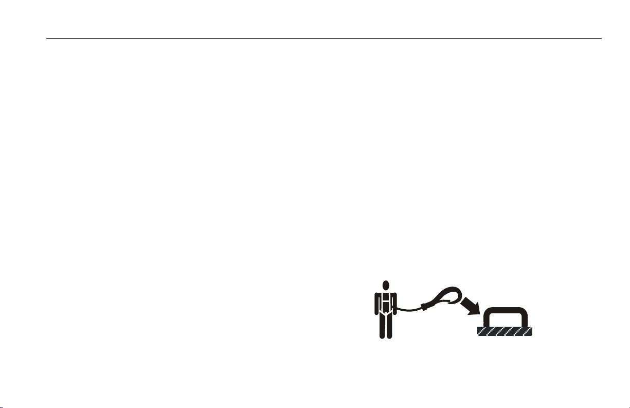
Trip and Fall Hazards
During operation, occupants in the platform must wear a full
body harness with a lanyard attached to an authorized lanyard anchorage point. Attach only one (1) lanyard per lanyard anchorage point.
3121218 – JLG Lift – 1-3
Page 14
SECTION 1 - SAFETY PRECAUTIONS
• Before operating the machine, make sure all gates are
closed and fastened in their proper position.
• Keep both feet firmly positioned on the platform floor at all
times. Never use ladders, boxes, steps, planks, or similar
items on platform to provide additional reach.
• Never use the boom assembly to enter or leave the platform.
• Use extreme caution when entering or leaving platform.
Be sure that the boom is fully lowered. It may be necessary to telescope out to position the platform closer to the
ground for entry/exit. Face the machine, maintain “three
point contact” with the machine, using two hands and one
foot or two feet and one hand during entry and exit.
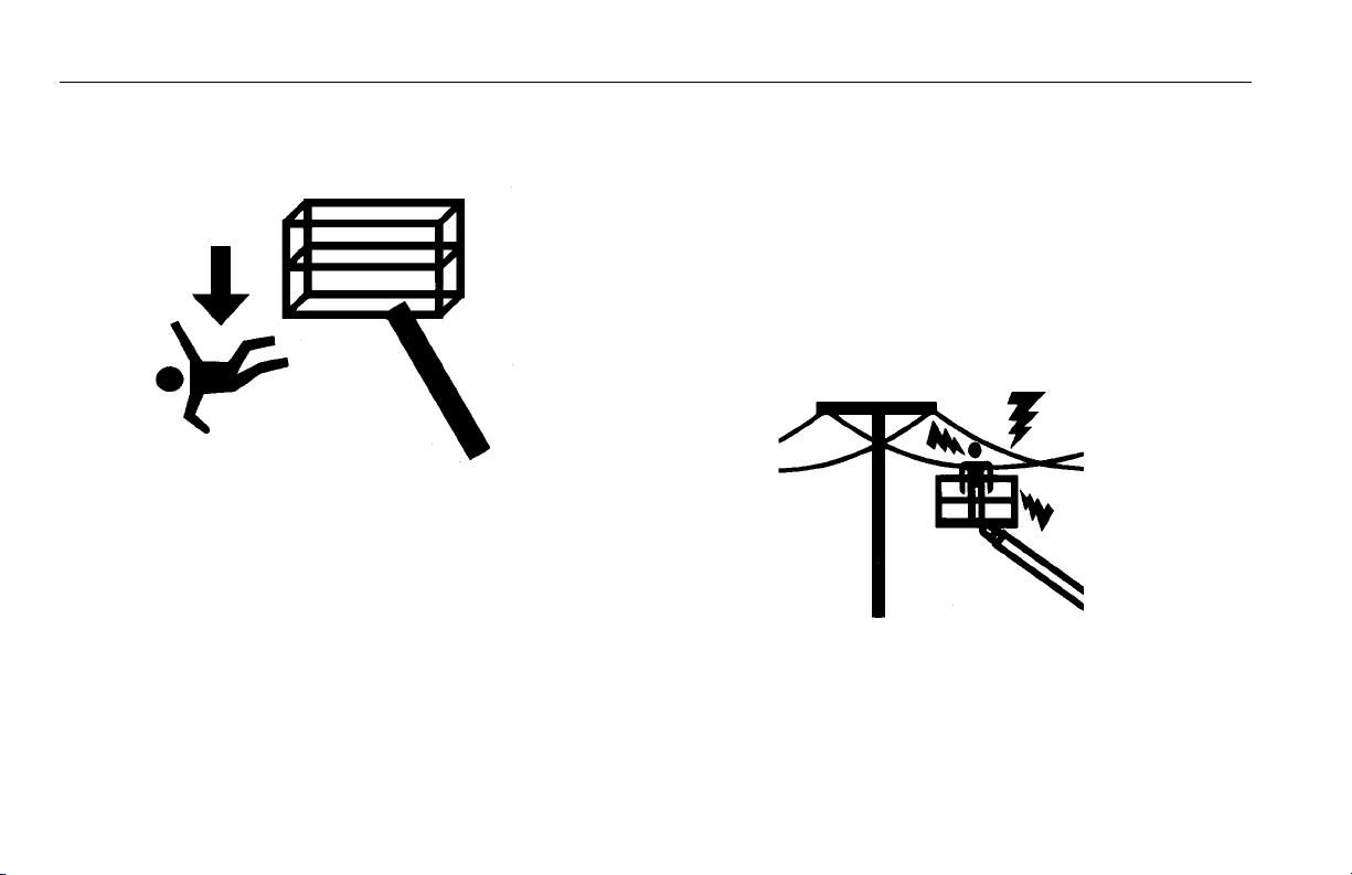
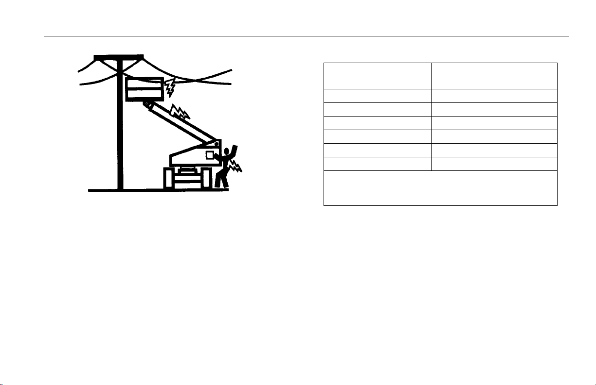
Electrocution Hazards
• This machine is not insulated and does not provide protection from contact or proximity to electrical current.
1-4 – JLG Lift – 3121218
Page 15
SECTION 1 - SAFETY PRECAUTIONS
Table 1-1. Minimum Approach Distances (M.A.D.)
• Maintain distance from electrical lines, apparatus, or any
energized (exposed or insulated) parts according to the
Minimum Approach Distance (MAD) as shown in Table 1-
1.
• Allow for machine movement and electrical line swaying.
Voltage Range
(Phase to Phase)
0 to 50 KV 10 (3)
Over 50KV to 200 KV 15 (5)
Over 200 KV to 350 KV 20 (6)
Over 350 KV to 500 KV 25 (8)
Over 500 KV to 750 KV 35 (11)
Over 750 KV to 1000 KV 45 (14)
NOTE: This requirement shall apply except where
employer, local or governmental regulations
are more stringent.
• Maintain a clearance of at least 10 ft. (3m) between any part
of the machine and its occupants, their tools, and their
equipment from any electrical line or apparatus carrying up
to 50,000 volts. One foot additional clearance is required for
every additional 30,000 volts or less.
MINIMUM APPROACH DISTANCE
in Feet (Meters)
3121218 – JLG Lift – 1-5
Page 16
SECTION 1 - SAFETY PRECAUTIONS
• The minimum approach distance may be reduced if insulating barriers are installed to prevent contact, and the barriers
are rated for the voltage of the line being guarded. These
barriers shall not be part of (or attached to) the machine. The
minimum approach distance shall be reduced to a distance
within the designed working dimensions of the insulating
barrier. This determination shall be made by a qualified person in accordance with the employer, local, or governmental
requirements for work practices near energized equipment
DO NOT MANEUVER MACHINE OR PERSONNEL INSIDE PROHIBITED
ZONE (MAD). ASSUME ALL ELECTRICAL PARTS AND WIRING ARE
ENERGIZED UNLESS KNOWN OTHERWISE.
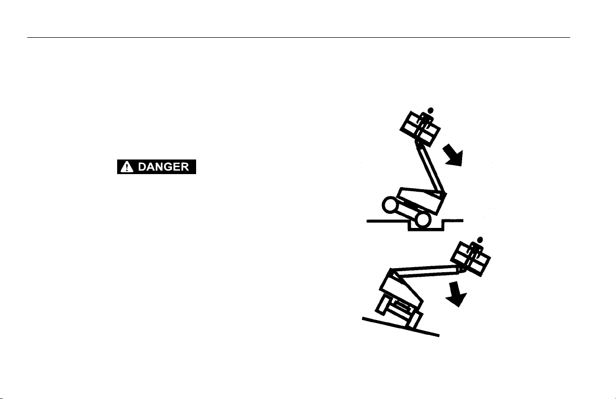
Tipping Hazards
• The user should be familiar with the surface before driving. Do not exceed the allowable sideslope and grade
while driving.
1-6 – JLG Lift – 3121218
Page 17
SECTION 1 - SAFETY PRECAUTIONS
• Do not elevate platform or drive with platform elevated
while on a sloping, uneven, or soft surface.
• Before driving on floors, bridges, trucks, and other surfaces, check allowable capacity of the surfaces.
• Never exceed the maximum platform capacity. Distribute
loads evenly on platform floor.
• Do not raise the platform or drive from an elevated position unless the machine is on firm, level and smooth surfaces.
• Keep the chassis of the machine at least 2 ft. (0.6m) from
holes, bumps, drop-offs, obstructions, debris, concealed
holes, and other potential hazards on the floor/surface.
• Do not push or pull any object with the boom.
• Never attempt to use the machine as a crane. Do not tieoff machine to any adjacent structure.
• Do not operate the machine when wind conditions exceed
28 mph (12.5 m/s).
• Do not increase the surface area of the platform or the
load. Increase of the area exposed to the wind will
decrease stability.
• Do not increase the platform size with unauthorized deck
extensions or attachments.
• If boom assembly or platform is in a position that one or
more wheels are off the ground, all persons must be
removed before attempting to stabilize the machine. Use
cranes, forklift trucks, or other appropriate equipment to
stabilize machine and remove personnel.
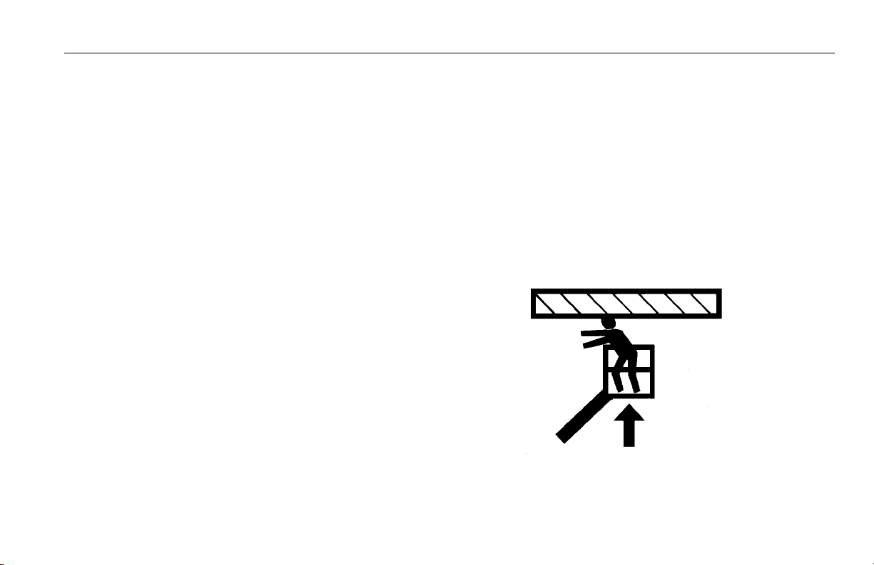
Crushing and Collision Hazards
• Approved head gear must be worn by all operating and
ground personnel.
• Check work area for clearances overhead, on sides, and
bottom of platform when lifting or lowering platform, and
driving.
• During operation, keep all body parts inside platform railing.
3121218 – JLG Lift – 1-7
Page 18

SECTION 1 - SAFETY PRECAUTIONS
• Use the boom functions, not the drive function, to position
the platform close to obstacles.
• Always post a lookout when driving in areas where vision
is obstructed.
• Keep non-operating personnel at least 6 ft. (1.8m) away
from machine during all driving and swing operations.
• Limit travel speed according to conditions of ground surface, congestion, visibility, slope, location of personnel,
and other factors which may cause collision or injury to
personnel.
• Be aware of stopping distances in all drive speeds. When
driving in high speed, switch to low speed before stopping. Travel grades in low speed only.
• Do not use high speed drive in restricted or close quarters
or when driving in reverse.
• Exercise extreme caution at all times to prevent obstacles
from striking or interfering with operating controls and persons in the platform.
• Be sure that operators of other overhead and floor level
machines are aware of the aerial work platform’s presence. Disconnect power to overhead cranes.
• Warn personnel not to work, stand, or walk under a raised
boom or platform. Position barricades on floor if necessary.
1.4 TOWING, LIFTING, AND HAULING
• Never allow personnel in platform while towing, lifting, or
hauling.
• This machine should not be towed, except in the event of
emergency, malfunction, power failure, or loading/unloading. Refer to the Emergency Procedures section of this
manual for emergency towing procedures.
• Ensure boom is in the stowed position and the turntable
locked prior to towing, lifting or hauling. The platform must
be completely empty of tools.
• When lifting machine, lift only at designated areas of the
machine. Lift the unit with equipment of adequate capacity.
• Refer to the Machine Operation section of this manual for
lifting information.
1-8 – JLG Lift – 3121218
Page 19

1.5 ADDITIONAL HAZARDS / SAFETY
• Do not use machine as a ground for welding.
• When performing welding or metal cutting operations,
precautions must be taken to protect the chassis from
direct exposure to weld and metal cutting spatter.
• Do not refuel the machine with the engine running.
• Battery fluid is highly corrosive. Avoid contact with skin
and clothing at all times.
• Charge batteries only in a well ventilated area.
SECTION 1 - SAFETY PRECAUTIONS
3121218 – JLG Lift – 1-9
Page 20

SECTION 1 - SAFETY PRECAUTIONS
This page left blank intentionally.
1-10 – JLG Lift – 3121218
Page 21

SECTION 2 - USER RESPONSIBILITIES, MACHINE PREPARATION, AND INSPECTION
SECTION 2. USER RESPONSIBILITIES, MACHINE PREPARATION, AND INSPECTION
2.1 PERSONNEL TRAINING
The aerial platform is a personnel handling device; so it is
necessary that it be operated and maintained only by trained
personnel.
Persons under the influence of drugs or alcohol or who are
subject to seizures, dizziness or loss of physical control must
not operate this machine.
Operator Training
Operator training must cover:
1. Use and limitations of the controls in the platform and at
the ground, emergency controls and safety systems.
2. Control labels, instructions, and warnings on the
machine.
3. Rules of the employer and government regulations.
4. Use of approved fall protection device.
5. Enough knowledge of the mechanical operation of the
machine to recognize a malfunction or potential malfunction.
6. The safest means to operate the machine where overhead obstructions, other moving equipment, and obstacles, depressions, holes, drop-offs.
7. Means to avoid the hazards of unprotected electrical
conductors.
8. Specific job requirements or machine application.
Training Supervision
Training must be done under the supervision of a qualified
person in an open area free of obstructions until the trainee
has developed the ability to safely control and operate the
machine.
Operator Responsibility
The operator must be instructed that he/she has the responsibility and authority to shut down the machine in case of a
malfunction or other unsafe condition of either the machine
or the job site.
3121218 – JLG Lift – 2-1
Page 22

SECTION 2 - USER RESPONSIBILITIES, MACHINE PREPARATION, AND INSPECTION
2.2 PREPARATION, INSPECTION, AND MAINTENANCE
The following table covers the periodic machine inspections
and maintenance recommended by JLG Industries, Inc.
Consult local regulations for further requirements for aerial
work platforms. The frequency of inspections and maintenance must be increased as necessary when the machine is
used in a harsh or hostile environment, if the machine is
used with increased frequency, or if the machine is used in a
severe manner.
IMPORTANT
JLG INDUSTRIES, INC. RECOGNIZES A FACTORY-CERTIFIED SERVICE
TECHNICIAN AS A PERSON WHO HAS SUCCESSFULLY COMPLETED
THE JLG SERVICE TRAINING SCHOOL FOR THE SPECIFIC JLG PRODUCT MODEL.
2-2 – JLG Lift – 3121218
Page 23

SECTION 2 - USER RESPONSIBILITIES, MACHINE PREPARATION, AND INSPECTION
Table 2-1.Inspection and Maintenance Table
Type Frequency
Pre-Start Inspection Before using each day; or
whenever there’s an Operator change.
Pre-Delivery Inspection
(See Note)
Frequent Inspection
(See Note)
Annual Machine Inspection
(See Note)
Preventative Maintenance At inter vals as specified in the Service and Main-
NOTE: Inspection forms are available from JLG. Use the Service and Maintenance Manual to perform inspections.
Before each sale, lease, or rental delivery. Owner, Dealer, or User Qualified JLG
In service for 3 months or 15 0 hours, whichever
comes first; or
Out of service for a period of more than 3 months;
or
Purchased used.
Annually, no later than 13 months from the date
of prior inspection.
tenance Manual.
Primary
Responsibility
User or Operator User or Operator Operator and Safety Manual
Owner, Dealer, or User Qualified JLG
Owner, Dealer, or User Factory-Cer tified
Owner, Dealer, or User Qualified JLG
Service
Qualification
Mechanic
Mechanic
Service Technician
(Recommended)
Mechanic
Reference
Service and Maintenance
Manual and applicable JLG
inspection form
Service and Maintenance
Manual and applicable JLG
inspection form
Service and Maintenance
Manual and applicable JLG
inspection form
Service and Maintenance
Manual
3121218 – JLG Lift – 2-3
Page 24

SECTION 2 - USER RESPONSIBILITIES, MACHINE PREPARATION, AND INSPECTION
Pre-Start Inspection
The Pre-Start Inspection should include each of the following:
1. Cleanliness – Check all surfaces for leakage (oil, fuel,
or battery fluid) or foreign objects. Report any leakage to
the proper maintenance personnel.
2. Structure - Inspect the machine structure for dents,
damage, weld or parent metal cracks or other discrepancies.
Parent Metal Crack Weld Crack
3. Decals and Placards – Check all for cleanliness and
legibility. Make sure none of the decals and placards are
missing. Make sure all illegible decals and placards are
cleaned or replaced.
4. Operators and Safety Manuals – Make sure a copy of
the Operator and Safety Manual, EMI Safety Manual
(Domestic only), and ANSI Manual of Responsibilities
(Domestic only) is enclosed in the weather resistant
storage container.
5. “Walk-Around” Inspection – Refer to Figure 2-2. thru
Figure 2-5.
6. Battery – Charge as required.
7. Fuel (Combustion Engine Powered Machines) – Add the
proper fuel as necessary.
8. Hydraulic Oil – Check the hydraulic oil level. Ensure
hydraulic oil is added as required.
9. Function Check – Once the “Walk-Around” Inspection
is complete, perform a functional check of all systems in
an area free of overhead and ground level obstructions.
Refer to Section 4 for more specific instructions.
IF THE MACHINE DOES NOT OPERATE PROPERLY, TURN OFF THE
MACHINE IMMEDIATELY! REPORT THE PROBLEM TO THE PROPER
MAINTENANCE PERSONNEL. DO NOT OPERATE THE MACHINE UNTIL
IT IS DECLARED SAFE FOR OPERATION.
2-4 – JLG Lift – 3121218
Page 25

SECTION 2 - USER RESPONSIBILITIES, MACHINE PREPARATION, AND INSPECTION
Function Check
Perform the Function Check as follows:
1. From the ground control panel with no load in the platform:
a. Check that all guards protecting the switches or
locks are in place;
b. Operate all functions and check all limiting and cut-
out switches;
c. Check auxiliary power (or manual descent);
d. Ensure that all machine functions are disabled
when the Emergency Stop Button is activated.
2. From the platform control console:
a. Ensure that the control console is firmly secured in
the proper location;
b. Check that all guards protecting the switches or
locks are in place;
c. Operate all functions and check all limiting and cut-
out switches;
d. Ensure that all machine functions are disabled
when the Emergency Stop Button is pushed in.
3. With the platform in the transport (stowed) position:
a. Drive the machine on a grade, not to exceed the
rated gradeability, and stop to ensure the brakes
hold;
b. Check the tilt sensor indicator light to ensure proper
operation.
3121218 – JLG Lift – 2-5
Page 26
SECTION 2 - USER RESPONSIBILITIES, MACHINE PREPARATION, AND INSPECTION
2.3 LIMIT SWITCH FUNCTIONAL CHECK
TO AVOID COLLISION AND INJURY IF PLATFORM DOES NOT STOP
WHEN A CONTROL SWITCH OR LEVER IS RELEASED, REMOVE FOOT
FROM FOOTSWITCH OR USE EMERGENCY STOP TO STOP THE
MACHINE.
NOTE: For adjustments see Service Manual - Limit Switch Adjust-
ments.
1. Check elevation limit and boom angle switches as follows:
a. Make sure the boom is fully lowered and retracted.
b. Verify the capacity indicator starts with the 1000 lb
(450 kg) light on. Raise the boom and verify the
capacity indicator changes to the 500 lb (230 kg)
light.
2. Check capacity limit and boom length switches as follows:
a. Make sure the boom is fully lowered and retracted.
b. Raise boom to horizontal.
c. Verify the capacity indicator starts with the 1000 lb
(450 kg) light on. Telescope the boom out and verify
the capacity indicator changes to the 500 lb (230
kg) light.
d. Retract the boom and verify the capacity indicator
changes to 1000 lb (450 kg) capacity.
TO AVOID COLLISION AND INJURY IF PLATFORM DOES NOT STOP
WHEN A CONTROL SWITCH OR LEVER IS RELEASED, REMOVE FOOT
FROM FOOTSWITCH OR USE EMERGENCY STOP TO STOP THE
MACHINE.
3. Raise main boom, extend and retract telescope. Check
for delayed movement of fly section, indicating loose
cables.
2-6 – JLG Lift – 3121218
Page 27

SECTION 2 - USER RESPONSIBILITIES, MACHINE PREPARATION, AND INSPECTION
4. Swing turntable to LEFT and RIGHT a minimum of 45
degrees. Check for smooth motion.
NOTE: Step 5 is only applicable for machines with an external tilt
sensor.
5. With the aid of an assistant to monitor the CHASSIS
OUT OF LEVEL indicator light on the platform control
console, manually activate the indicator light by compressing any one of the three tilt indicator mounting
springs. If the light does not illuminate, shut down
machine and contact a qualified service technician
before continuing operation.
NOTE: Step 6 is applicable for machines with an internal tilt sen-
sor.
6. Check the chassis out of level indicator located on the
platform control console by driving, with the machine in
level position, up a suitable ramp of at least 5° slope.
Check the out of level indicator, with the machine on the
ramp. If the light does not illuminate, return the machine
to a level surface, shut down the machine, and contact a
qualified technician before resuming operation.
3121218 – JLG Lift – 2-7
Page 28
SECTION 2 - USER RESPONSIBILITIES, MACHINE PREPARATION, AND INSPECTION
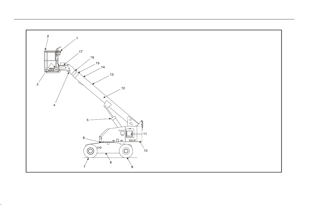
1. Platform Control Box
2 . P l a tf o rm
3 . F o ot s wi t c h
4. Slave Level Cylinder
5 . L i f t Cy l in d er
6 . S w i ng B ea r in g
7. Drive Wheels
8 . F r am e
9. Steer Wheels
10. Turntable
11. Ground Control Box
12. Telescope Cylinder (Inside)
13. Boom Assembly
14. Base Boom
15. Mid Boom
16. Fly Boom
17. Rotator
Figure 2-1. Machine Nomenclature
2-8 – JLG Lift – 3121218
Page 29
SECTION 2 - USER RESPONSIBILITIES, MACHINE PREPARATION, AND INSPECTION
Figure 2-2. Daily Walk-Around Inspection - Sheet 1 of 4
3121218 – JLG Lift – 2-9
Page 30

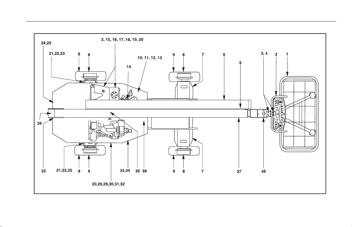
SECTION 2 - USER RESPONSIBILITIES, MACHINE PREPARATION, AND INSPECTION
General
Begin the "Walk-Around Inspection" at Item 1, as noted on
the diagram. Continue to the right (counterclockwise
viewed from top) checking each item in sequence for the
conditions listed in the following checklist.
TO AVOID POSSIBLE INJURY, BE SURE MACHINE POWER IS OFF.
DO NOT OPERATE MACHINE UNTIL ALL MALFUNCTIONS HAVE
BEEN CORRECTED.
INSPECTION NOTE: On all components, make sure there
are no loose or missing parts, that they are securely fastened, and no visible damage, leaks or excessive wear
exists in addition to any other criteria mentioned.
1. Platform Assembly and Gate - Lockbolts in place.
Footswitch works properly, not modified, disabled or
blocked. Latch, stop, and hinges in working condition.
2. Platform & Ground Control Consoles - Switches
and levers return to neutral, decals/placards secure
and legible, control markings legible.
Figure 2-3. Daily Walk-Around Inspection - Sheet 2 of 4
3. Rotator - See Inspection Note.
4. Rotator Motion Control Valve - See Inspection Note.
5. Dual Capacity Limit Switch - See Inspection Note.
6. Power Track - See Inspection Note.
7. Drive Motor and Brake - See Inspection Note.
8. Drive Hub, Right Rear - See Inspection Note.
9. Wheel/Tire Assemblies - Properly secured, no miss-
ing lug nuts, proper inflation (pneumatic).
10. Turntable Lock - Operable; See Inspection Note.
11. Auxiliary Power Pump - See Inspection Note.
12. Swing Drive Motor and Brake - See Inspection Note.
13. Control Valve (Tank Compartment) - See Inspection
Note.
14. Turntable Bearing and Pinion - See Inspection Note.
No evidence of loose bolts or looseness between
bearing and structure.
2-10 – JLG Lift – 3121218
Page 31

SECTION 2 - USER RESPONSIBILITIES, MACHINE PREPARATION, AND INSPECTION
15. Hydraulic Oil Return Filter Housing - See Inspection
Note.
16. LP Gas Tank - See Inspection Note. (If Equipped)
17. Hydraulic Oil Supply - Recommended oil level sight
gauge. (Check level with cold oil, systems shut down,
machine in stowed position) Cap in place and secure.
18. Hydraulic Oil Breather - Element in place, not
clogged, no sign of overflow.
19. Fuel Supply - Fuel filler cap secure. Tank - See Inspection Note.
20. Door and Latches - See Inspection Note.
21. Drive Motor - See Inspection Note.
22. Spindle - See Inspection Note.
23. Tie Rod and Steering Linkage - See Inspection Note.
Figure 2-4. Daily Walk-Around Inspection - Sheet 3 of 4
24. Oscillating Cam Valve - See Inspection Note. (If
Equipped)
25. All Hydraulic Cylinders - No visible damage; pivot
pins and hydraulic hoses undamaged, not leaking.
26. Oscillating Axle - See Inspection Note.
27. Horizontal Cutout Switch - See Inspection Note. No
damage to the switch, arm free to move, and free from
dirt and grease.
28. Engine Air Filter - See Inspection Note; element
clean.
29. Battery - Proper electrolyte levels; cables tight, no visible damage or corrosion.
30. Engine Oil Supply - Full mark on dipstick; filler cap
secure.
3121218 – JLG Lift – 2-11
Page 32

SECTION 2 - USER RESPONSIBILITIES, MACHINE PREPARATION, AND INSPECTION
31. Muffler and Exhaust System - See Inspection Note.
32. Hydraulic Pump - See Inspection Note.
33. Engine Tray Pivot - See Inspection Note.
34. Hydraulic Oil Medium Pressure Filter Housing -
Housing secure; See Inspection Note.
35. Hydraulic Swivel - See Inspection Note.
Figure 2-5. Daily Walk-Around Inspection - Sheet 4 of 4
36. Horizontal Cutoff Limit Switch - (High Engine/High
Drive Cut-off Switch) properly secured, no damage to
the switch, arm free to move, and free from dirt and
grease.
37. Boom Sections - No visible damage; wear pads
secure.
38. Platform Pivot Pin - See Inspection Note.
2-12 – JLG Lift – 3121218
Page 33

SECTION 3 - MACHINE CONTROLS AND INDICATORS
SECTION 3. MACHINE CONTROLS AND INDICATORS
3.1 GENERAL
IMPORTANT
THE MANUFACTURER HAS NO DIRECT CONTROL OVER MACHINE
APPLICATION AND OPERATION. THE USER AND OPERATOR ARE
RESPONSIBLE FOR CONFORMING WITH GOOD SAFETY PRACTICES.
This section provides the necessary information needed to
understand control functions.
3.2 CONTROLS AND INDICATORS
NOTE: All machines are equipped with control panels that use
symbols to indicate control functions. On ANSI machines
refer to decal located on the control box guard in front of
the control box or by the ground controls for these symbols and the corresponding functions.
NOTE: The indicator panels use different shaped symbols to alert
the operator to different types of operational situations
that could arise. The meaning of those symbols are
explained below.
Indicates a potentially hazardous situation, which
if not corrected, could result in serious injury or
death. This indicator will be red.
Indicates an abnormal operating condition,
which if not corrected, may result in machine
interruption or damage. This indicator will be yellow.
Indicates important information regarding the
operating condition, i.e. procedures essential for
safe operation. This indicator will be green with
the exception of the capacity indicator which will
be green or yellow depending upon platform
position.
3121218 – JLG Lift – 3-1
Page 34

SECTION 3 - MACHINE CONTROLS AND INDICATORS
Ground Control Station
See Figure 3-1., Ground Control Panel.
NOTE: If equipped, the Function Enable switch must
be held down in order to operate Telescope,
Swing, Lift, Jib Lift, Platform Level Override,
and Platform Rotate functions.
1. Platform Rotate
A three position ROTATE control switch permits rotation
of the platform when positioned to LEFT or RIGHT.
2. Platform Leveling Override
A three position switch allows the operator to compensate for any difference in the automatic self leveling system.
NOTE: When Power/Emergency Stop switch is in the “ON” posi-
tion and engine is not running, an alarm will sound, indicating Ignition is “ON”.
WHEN THE MACHINE IS SHUT DOWN THE MASTER/EMERGENCY STOP
SWITCH MUST BE POSITIONED TO THE “OFF” POSITION TO PREVENT
DRAINING THE BATTERY.
NOTE: On machines with diesel engines, when Glow Plug Indi-
cator is lighted (Yellow), wait until light goes out before
cranking engine.
3. Power/Emergency Stop Switch
A two-position red mushroom shaped switch supplies
power to PLATFORM/GROUND SELECT switch when
pulled out (on). When pushed in (off), power is shut off
to the PLATFORM/GROUND SELECT switch.
4. Engine Start/Auxiliary Power Switch
or
Engine Start/ Auxiliary Power Switch /Function Enable
To start the engine, the switch must be held
"UP" until the engine starts.
To use auxiliary power, the switch must be
held “DOWN” for duration of auxiliary pump
use. Aux power can only be used if the
engine is not running.
If equipped, the enable switch must be held
"DOWN" to enable all boom controls when
the engine is running.
NOTE: Auxiliary power only works if there is no engine oil pres-
sure, and is disabled if engine is running.
3-2 – JLG Lift – 3121218
Page 35

1. Platform Rotate
2. Platform Leveling Override
3. Power/Emergency Stop
4. Engine Star t/Auxiliary Power
or
E n gi n e S t ar t / A ux i li a r y P o we r /F u nc t io n En a b le
5. Lift
6. Hourmeter
7. Platform/Ground Select Switch
8. Swing
9. Boom Telescope
SECTION 3 - MACHINE CONTROLS AND INDICATORS
Figure 3-1. Ground Control Panel
3121218 – JLG Lift – 3-3
Page 36

SECTION 3 - MACHINE CONTROLS AND INDICATORS
NOTE: Lift, Swing, Platform Level, Telescope, Platform Rotator
and Auxiliary control switches are spring-loaded and will
automatically return to neutral (off) when released.
WHEN OPERATING THE BOOM ENSURE THERE ARE NO PERSONNEL
AROUND OR UNDER PLATFORM.
TO AVOID SERIOUS INJURY, DO NOT OPERATE MACHINE IF ANY CONTROL LEVERS OR TOGGLE SWITCHES CONTROLLING PLATFORM
MOVEMENT DO NOT RETURN TO THE OFF POSITION WHEN
RELEASED.
5. Lift Control
Provides raising and lowering of the main boom.
6. Hourmeter
The hourmeter registers up to 9,999.9 hours and cannot
be reset.
7. Platform/Ground Select
A three position, key operated switch supplies power to
the platform control console when positioned to Platform. With the switch key held in the Ground position,
power is shut off to platform and only ground controls
are operable.
NOTE: With the Platform/Ground Select Switch in the center posi-
tion, power is shut off to controls at both operating stations.
8. Swing Control
Provides 360 degrees continuous turntable rotation.
9. Telescope Control.
Provides extension and retraction of the boom, when
positioned to IN or OUT.
3-4 – JLG Lift – 3121218
Page 37

SECTION 3 - MACHINE CONTROLS AND INDICATORS
Ground Control Indicator Panel
(See Figure 3-2., Ground Control Indicator Panel)
1. Battery Charging
2. Low Engine Oil Pressure
3. Engine Coolant Temp.
4. High Engine Oil Temp.
Figure 3-2. Ground Control Indicator Panel
1. Battery Charging Indicator
When illuminated indicates a problem in the battery or
charging circuit, and service is required.
5. Engine Malfunction Indicator
6. Low Fuel
7. Platform Overload
2. Low Engine Oil Pressure Indicator
When illuminated indicates that engine oil pressure is
below normal and service is required.
3. Engine Coolant Temperature (Ford) Indicator
When illuminated indicates that engine coolant temperature is abnormally high and service is required.
4. Engine Oil Temperature Indicator (Deutz)
When illuminated indicates that the temperature of the
engine oil, which also serves as engine coolant, is
abnormally high and service is required.
5. Engine Malfunction Indicator Light (Ford Engines
S/N 58209 to S/N 60444)
When illuminated, indicates that the Engine Control
Module has detected a malfunction in the Electronic
Fuel Injection System and a Diagnostic Trouble Code
has been set in the ECM. Refer to the Service Manual for
instructions concerning the trouble codes and trouble
code retrieval.
The malfunction indicator light will illuminate for 2-3 seconds when the key is positioned to the on position to act
as a self test.
3121218 – JLG Lift – 3-5
Page 38

SECTION 3 - MACHINE CONTROLS AND INDICATORS
Figure 3-3. Malfunction Indicator Light and Test Button
6. Platform Overload (If equipped)
7. EFI System Test Button (Ford Engines S/N 58209 to S/N
60444)
By pushing and holding the system test button on the
side of the ground control box, the Diagnostic Trouble
Codes will be displayed on the Malfunction Indicator
Light. Refer to the Service Manual for instructions concerning the trouble codes and trouble code retrieval.
Indicates the platform has been overloaded.
3-6 – JLG Lift – 3121218
Page 39

Platform Station
SECTION 3 - MACHINE CONTROLS AND INDICATORS
(See Figure 3-4., Platform Control Console)
DO NOT OPERATE MACHINE IF DRIVE SPEED /TORQUE SELECT
SWITCH OPERATES WHEN BOOM IS ABOVE HORIZONTAL.
1. Drive Speed/Torque Select
The machine has a three position switch - The forward
position gives maximum drive speed by shifting the
drive motors to minimum the displacement and giving
high engine when drive controller is moved. The back
position gives maximum torque for rough terrain and
climbing grades by shifting the wheel motors to maximum displacement and giving high engine speed when
drive controller is moved. The center position allows the
machine to be driven as quietly as possible by leaving
the engine at mid speed and the drive motors in maximum displacement.
TO AVOID SERIOUS INJURY, DO NOT OPERATE MACHINE IF ANY CONTROL LEVERS OR TOGGLE SWITCHES CONTROLLING PLATFORM
MOVEMENT DO NOT RETURN TO THE OFF OR NEUTRAL POSITION
WHEN RELEASED.
2. Platform Leveling Override
This switch allows the operator to adjust the level of the
platform.
3. Horn
Supplies electrical power to an audible warning device
when pressed.
4. Power/Emergency Stop
An ON-OFF POWER/EMERGENCY STOP switch and a
separate ENGINE START/AUXILIARY POWER toggle
switch on the platform console supply electrical power
to the starter solenoid, when the ignition switch is placed
in the “ON” position and the ENGINE START switch is
push forward.
3121218 – JLG Lift – 3-7
Page 40

SECTION 3 - MACHINE CONTROLS AND INDICATORS
1. Drive Speed/Torque Select
2. Platform Leveling Over ride
3. Horn
4. Power/Emergency Stop
Figure 3-4. Platform Control Console
5. Engine Star t/Aux. Power
6. Fuel Select
7. Drive/Steer
8. Telescope
9. Platform Rotate
10. Main Lift/Swing
3-8 – JLG Lift – 3121218
Page 41

SECTION 3 - MACHINE CONTROLS AND INDICATORS
5. Auxiliary Power
Energizes the electrically operated hydraulic pump,
when actuated. (Switch must be held ON for duration of
auxiliary pump use.)
The auxiliary pump functions to provide sufficient oil flow
to operate the basic machine functions should the main
pump or engine fail. The auxiliary pump will operate
tower boom lift, tower telescope, main boom lift, main
telescope and swing.
6. Fuel Select (Dual Fuel Engine Only)
Gasoline or liquid propane fuel may be selected by moving the switch to the appropriate position. It is unnecessary to purge the fuel system before switching fuels, so
there is no waiting period when switching fuels while the
engine is running.
NOTE: MAIN LIFT, SWING, and DRIVE control levers are spring-
loaded and will automatically return to neutral (OFF) position when released.
7. Drive/Steer
Proportional single axis joystick is provided to control
drive. Push forward to drive forward, pull back to drive in
reverse. Steering is accomplished via a thumb-activated
rocker switch on the end of the handle. Push on the left
side of the switch to steer left, on right side to steer right.
NOTE: Both drive and steer functions work in the opposite direc-
tion when the boom is positioned over front of the chassis.
NOTE: When boom is positioned above horizontal and the DRIVE
SPEED/TORQUE SELECT switch is positioned to HIGH,
high function speeds are automatically cut out and the
machine continues to operate at a lower speed.
3121218 – JLG Lift – 3-9
Page 42

SECTION 3 - MACHINE CONTROLS AND INDICATORS
8. Te l e s c o p e C o n t r o l
This control allows extension and retraction of the main
boom.
9. Platform Rotate
This switch allows the operator to rotate the basket to
the left or right.
10. Main Lift/Swing Controller
An infinitely proportional dual axis joystick is provided
for main lift and swing. Push forward to lift up, pull backward to lift down. Move right to swing right, move left to
swing left.
NOTE: Main lift and swing functions may be selected in combina-
tion. The handle features a round gate so that maximum
speed is reduced when multiple functions are selected.
Platform Control Indicator Panel
See Figure 3-5., Platform Control Indicator Panel.
1. Tilt
2. Overload
3. Capacity
Figure 3-5. Platform Control Indicator Panel
4. Enable
5. Engine Distress
6. Creep
3-10 – JLG Lift – 3121218
Page 43

SECTION 3 - MACHINE CONTROLS AND INDICATORS
1. Tilt Alarm Warning Light. (Orange)
This orange illuminator indicates that the chassis is on a
slope (over 5 degrees). If illuminated when boom is
raised or extended, retract and lower to below horizontal
then reposition machine so that it is level before extending boom or raising boom above horizontal. If the boom
is above horizontal and the machine is on a 5 degree
slope, an alarm will sound and CREEP is automatically
activated.
2. Platform Overload (If equipped)
Indicates the platform has been overloaded.
3. Capacity Indicator
When illuminated (Red), the light indicates the maximum
platform capacity for the current position of the platform.
1000 pounds (450 kg) capacity is permitted at restricted
platform positions (shorter boom lengths and higher
boom angles), and 500 pounds (230 kg) is the maximum capacity in all other positions.
4. Enable Indicator/Footswitch
To operate any function, the footswitch must be
depressed and the function selected within seven seconds. The enable indicator shows that the controls are
enabled. If a function is not selected within seven seconds, or if a seven second lapse between ending one
function and beginning the next function, the enable
light will go out and the footswitch must be released and
depressed again to enable the controls.
Releasing the footswitch removes power from all controls and applies the drive brakes.
TO AVOID SERIOUS INJURY, DO NOT REMOVE, MODIFY OR DISABLE
THE FOOTSWITCH BY BLOCKING OR ANY OTHER MEANS.
FOOTSWITCH MUST BE ADJUSTED IF FUNCTIONS ACTIVATE WHEN
SWITCH ONLY OPERATES WITHIN LAST 1/4" OF TRAVEL, TOP OR BOTTOM.
3121218 – JLG Lift – 3-11
Page 44

SECTION 3 - MACHINE CONTROLS AND INDICATORS
5. Engine Malfunction Indicator
On all machines prior to S/N 58209 and machines with a
Deutz engine prior to S/N 60188, the light turns on and
an alarm sounds when machine’s power system
requires immediate service. Any of the following conditions will turn on light and alarm: low engine oil pressure, high engine coolant temperature, clogged engine
air filter, low alternator output, clogged hydraulic oil
return filter, or clogged charge pump filter.
On machines with Ford engines from S/N 58209 and
machines with Deutz engines after S/N 60188, the light
indicates that the Engine Control System has detected a
malfunction and a Diagnostic Trouble Code has been
set in the system memory. Refer to the Service Manual
for instructions concerning the trouble codes and trouble code retrieval.
The malfunction indicator light will illuminate for 2-3 seconds when the key is positioned to the on position to act
as a self test.
6. Creep Speed Indicator
Illuminated (Green) for Boom functions when the boom
is above horizontal and the machine is tilted and for
Drive functions when the boom is above horizontal. The
indicator acts as a reminder that all functions are set to
the slowest speed.
3-12 – JLG Lift – 3121218
Page 45

SECTION 4 - MACHINE OPERATION
SECTION 4. MACHINE OPERATION
4.1 DESCRIPTION
This machine is a self-propelled hydraulic personnel lift
equipped with a work platform on the end of an elevating
and rotating boom. Vibrations emitted by these machines
are not hazardous to an operator in the work platform. The
equivalent continuous A-Weighted sound pressure level at
the work platform is less than 75dB(A).
The primary operator control station is in the platform. From
this control station, the operator can drive and steer the
machine in both forward and reverse directions. The operator can raise or lower the main or tower boom or swing the
boom to the left or right. Standard boom swing is 360 degree
continuous left and right of the stowed position. The machine
has a Ground Control Station which will override the Platform
Control Station. Ground Controls operate Boom Lift and
Swing, and are to be used in an emergency to lower the platform to the ground should the operator in the platform be
unable to do so.
4.2 OPERATING CHARACTERISTICS AND LIMITATIONS
Capacities
The boom can be raised above horizontal with or without any
load in platform, if:
1. Machine is positioned on a smooth, firm and level surface.
2. Load is within manufacturer’s rated capacity.
3. All machine systems are functioning properly.
4. Proper tire pressure.
5. Machine is as originally equipped from JLG.
3121218 – JLG Lift – 4-1
Page 46

SECTION 4 - MACHINE OPERATION
Stability
Machine stability is based on two positions which are called
FORWARD and BACKWARD stability. The machines position
of least FORWARD stability is shown in Figure 4-2., Position
of Least Forward Stability, and its position of least BACKWARD stability is shown in Figure 4-1., Position of Least
Backward Stability.
TO AVOID FORWARD OR BACKWARD TIPPING, DO NOT OVERLOAD
MACHINE OR OPERATE THE MACHINE ON AN OUT-OF-LEVEL SURFACE.
PLATFORM ROTATED
9O DEGREES
MACHINE WILL UPSET
IN THIS DIRECTION IF
OPERATED ON
AN OUT-OF-LEVEL SURFACE
MAIN BOOM
FULLY RETRACTED
AND ELEVATED
LEVEL SURFACE
Figure 4-1. Position of Least Backward Stability
4-2 – JLG Lift – 3121218
Page 47

MACHINE WILL UPSET IN THIS
DIRECTION IF OVERLOADED
OR OPERATED ON AN
OUT-OF-LEVEL SURFACE
SECTION 4 - MACHINE OPERATION
BOOM FULLY EXTENDED
@ HORIZONTAL (O DEGREES)
LEVEL SURFACE
Figure 4-2. Position of Least Forward Stability
3121218 – JLG Lift – 4-3
Page 48

SECTION 4 - MACHINE OPERATION
4.3 ENGINE OPERATION
NOTE: Initial starting should always be performed from the
Ground Control station.
Starting Procedure
IF ENGINE FAILS TO START PROMPTLY, DO NOT CRANK FOR AN
EXTENDED TIME. SHOULD ENGINE FAIL TO START AGAIN, ALLOW
STARTER TO “COOL OFF” FOR 2-3 MINUTES. IF ENGINE FAILS AFTER
SEVERAL ATTEMPTS, REFER TO ENGINE MAINTENANCE MANUAL.
NOTE: Diesel engines only: After turning on ignition, operator
must wait until glow plug indicator light goes out before
cranking engine.
1. Turn key of SELECT switch to GROUND. Position
POWER/EMERGENCY STOP switch to ON, then push
the ENGINE START switch until engine starts.
ALLOW ENGINE TO WARM-UP FOR A FEW MINUTES AT LOW SPEED
BEFORE APPLYING ANY LOAD.
2. After engine has had sufficient time to warm up, shut
engine off.
3. Turn SELECT switch to PLATFORM.
4. From Platform, pull POWER/EMERGENCY STOP switch
out, then push the ENGINE START switch until engine
starts.
NOTE: Footswitch must be in released (up) position before
starter will operate. If starter operates with footswitch in
the depressed position, DO NOT OPERATE MACHINE.
4-4 – JLG Lift – 3121218
Page 49

SECTION 4 - MACHINE OPERATION
Shutdown Procedure
IF AN ENGINE MALFUNCTION CAUSES AN UNSCHEDULED SHUTDOWN, DETERMINE THE CAUSE AND CORRECT IT BEFORE RESTARTING THE ENGINE.
1. Remove all load and allow engine to operate at low
speed for 3-5 minutes; this allows further reduction of
internal engine temperature.
2. Push POWER/EMERGENCY STOP switch in.
3. Turn MASTER switch to Off.
Refer to Engine Manufacturer’s manual for detailed information.
4.4 TRAVELING (DRIVING)
DO NOT DRIVE WITH BOOM EXTENDED OR ABOVE HORIZONTAL
EXCEPT ON A SMOOTH, FIRM AND LEVEL SURFACE.
TO AVOID LOSS OF TRAVEL CONTROL OR UPSET ON GRADES AND
SIDESLOPES, DO NOT DRIVE MACHINE ON GRADES OR SIDESLOPES
EXCEEDING THOSE SPECIFIED ON WARNING PLACARD AT PLATFORM.
ASSURE THAT TURNTABLE LOCK IS ENGAGED BEFORE BEGINNING
ANY EXTENDED TRAVELING. AVOID ANY TERRAIN FEATURES WHICH
COULD CAUSE THE MACHINE TO UPSET.
TRAVEL GRADES WITH DRIVE SPEED/TORQUE SELECT SWITCH IN
THE BACKWARD (MAXIMUM TORQUE) POSITION. USE EXTREME CAUTION WHEN DRIVING IN REVERSE AND AT ALL TIMES WHEN DRIVING
WITH PLATFORM ELEVATED AND ESPECIALLY WHEN DRIVING WITH
ANY PART OF MACHINE WITHIN 6 FEET (2 M) OF AN OBSTRUCTION.
DO NOT USE DRIVE TO MANEUVER PLATFORM CLOSE TO AN
OBSTRUCTION...USE ONE OF THE BOOM FUNCTIONS.
3121218 – JLG Lift – 4-5
Page 50

SECTION 4 - MACHINE OPERATION
S
I
D
E
S
L
O
P
E
Do Not Drive Machine On Grades Exceeding
LEVEL
Those As Specified In Table 6-1.
G
R
A
D
E
Figure 4-3. Grade and Sideslope
4-6 – JLG Lift – 3121218
Page 51

BEFORE DRIVING, MAKE SURE BOOM IS POSITIONED OVER REAR
AXLE. IF BOOM IS OVER FRONT AXLE (STEER WHEELS), STEER AND
DRIVE CONTROLS WILL MOVE IN OPPOSITE DIRECTIONS TO MACHINE
CONTROLS.
SECTION 4 - MACHINE OPERATION
5. Prior to stopping the machine, position switches as follows:
Position DRIVE SPEED/TORQUE SELECT switch to
LOW. (Middle Position)
6. For traveling up grades, position switches as follows:
Traveling Forward or Reverse
1. With engine running, depress footswitch and position
DRIVE control to FORWARD and hold for the duration of
forward travel desired.
2. Depress footswitch and position DRIVE control to
REVERSE and hold for duration of reverse travel
desired.
3. Depress footswitch and position STEER control to
RIGHT for traveling right and LEFT for traveling left.
4. To obtain maximum travel speed, position the DRIVE
controller to FAST and activate the following switches:
Position DRIVE SPEED/TORQUE SELECT switch to
HIGH. (Forward Position)
NOTE: For smoother operation when driving with fully extended
4.5 STEERING
BEFORE OPERATING MACHINE, MAKE SURE BOOM IS POSITIONED
OVER REAR AXLE. IF BOOM IS OVER FRONT AXLE (STEER WHEELS),
STEER AND DRIVE CONTROLS WILL MOVE IN OPPOSITE DIRECTION
THAN INDICATED ON MACHINE PLACARDS.
Position DRIVE SPEED/TORQUE SELECT switch to
HIGH. (Backward position).
boom, place DRIVE control to SLOW before stopping.
Depress footswitch to steer machine, push on the left side of
the switch to steer left, on the right side to steer right.
3121218 – JLG Lift – 4-7
Page 52

SECTION 4 - MACHINE OPERATION
4.6 PARKING AND STOWING
Park and stow machine as follows:
1. Park machine in travel position; boom lowered over rear,
all access panels and doors closed and secured, ignition off, turntable locked.
2. Check that brakes hold machine in position.
3. Chock wheels front and rear.
4. Turn off SELECT switch and remove key.
4.7 PLATFORM
Loading From Ground Level
1. Position chassis on a smooth, firm and level surface.
2. If total load (personnel, tools and supplies) is less then
rated capacity, distribute load uniformly on platform floor
and proceed to work position.
Loading From Positions Above Ground Level
Before loading weight to platform above ground level:
1. Determine what the total rated capacity weight will be
after additional weight is loaded (personnel, tools and
supplies).
2. If total weight in platform will be less then rated capacity,
proceed with adding weight.
Platform Level Adjustment
1. Leveling UP. Depress footswitch To raise platform, position PLATFORM LEVEL control switch UP and hold until
platform is level.
2. Leveling DOWN. Depress footswitch To lower platform,
position PLATFORM LEVEL control switch to DOWN and
hold until platform is level.
4-8 – JLG Lift – 3121218
Page 53

SECTION 4 - MACHINE OPERATION
Platform Rotation
1. Depress footswitch to rotate platform to the left, PLATFORM ROTATE control is positioned to the LEFT and
held until desired position is reached.
2. Depress footswitch to rotate platform to the right, PLATFORM ROTATE control is positioned to the RIGHT and
held until desired position is reached.
4.8 BOOM
AN ORANGE TILT ALARM WARNING LIGHT, LOCATED ON THE CONTROL CONSOLE, LIGHTS WHEN THE CHASSIS IS ON A SEVERE SLOPE
(5 DEGREES OR GREATER). DO NOT SWING, EXTEND OR RAISE MAIN
BOOM ABOVE HORIZONTAL WHEN LIT.
DO NOT DEPEND ON TILT ALARM AS A LEVEL INDICATOR FOR THE
CHASSIS. TILT ALARM INDICATES CHASSIS IS ON A SEVERE SLOPE (5
DEGREES OR GREATER). CHASSIS MUST BE LEVEL BEFORE SWINGING, EXTENDING OR RAISING TOWER BOOM ABOVE HORIZONTAL.
TO AVOID UPSET, IF ORANGE TILT ALARM WARNING LIGHT LIGHTS
WHEN MAIN BOOM IS EXTENDED OR RAISED ABOVE HORIZONTAL,
RETRACT AND LOWER PLATFORM TO NEAR GROUND LEVEL. THEN
REPOSITION MACHINE SO THAT CHASSIS IS LEVEL BEFORE EXTEND-
ING OR RAISING BOOM.
TRAVELING WITH BOOM RETRACTED AND BELOW HORIZONTAL IS
PERMITTED ON GRADES NOT EXCEEDING THE MACHINES’ GRADEABLITY AND ON SIDE SLOPES SPECIFIED IN TABLE 6-1.
TO AVOID SERIOUS INJURY, DO NOT OPERATE MACHINERY IF ANY
CONTROL LEVERS OR TOGGLE SWITCHES CONTROLLING PLATFORM
MOVEMENT DO NOT RETURN TO THE OFF OR NEUTRAL POSITION
WHEN RELEASED.
TO AVOID A COLLISION AND INJURY IF PLATFORM DOES NOT STOP
WHEN A CONTROL SWITCH OR LEVER IS RELEASED, REMOVE FOOT
FROM FOOTSWITCH OR USE EMERGENCY STOP TO STOP THE
MACHINE.
3121218 – JLG Lift – 4-9
Page 54

SECTION 4 - MACHINE OPERATION
Swinging the Boom
IMPORTANT
ASSURE THAT TURNTABLE LOCK IS DISENGAGED BEFORE STARTING
ANY SWING OPERATION.
Depress footswitch to swing boom, position SWING control
switch or controller to RIGHT or LEFT for direction desired.
Raising and Lowering the Main Boom
To raise and lower Main Boom, position MAIN LIFT control
switch or controller to UP OR DOWN and hold until desired
height is reached.
Telescoping the Main Boom
To extend or retract Main Boom, position MAIN TELESCOPE
control switch to IN or OUT and hold until platform reaches
desired position.
4.9 DUAL FUEL SYSTEM (GAS ENGINE ONLY)
The dual fuel system enables the standard gasoline engine
to run on either gasoline or LP gas. The system includes
pressurized cylinders mounted on the frame, and the valves
and switches needed to switch the fuel supply from gasoline
to LP gas or from LP gas to gasoline.
A two position, FUEL SELECT toggle switch at the platform
control station supplies electrical power to open the gasoline
shut-off solenoid and close the LP gas shut off solenoid
when positioned to the GASOLINE position. This switch supplies electrical power to open the LP gas shut-off solenoid
and close the gasoline shut-off solenoid when positioned to
the LP position.
4-10 – JLG Lift – 3121218
Page 55

SECTION 4 - MACHINE OPERATION
4.10 SHUT DOWN AND PARK
IT IS POSSIBLE TO SWITCH FROM ONE FUEL SOURCE TO THE OTHER
WITHOUT ALLOWING THE ENGINE TO STOP. EXTREME CARE MUST BE
TAKEN AND THE FOLLOWING INSTRUCTIONS MUST BE FOLLOWED.
Changing From Gasoline to LP Gas
1. Start engine from Ground Control Station.
2. Open hand valve on LP gas supply tank by turning
counterclockwise.
3. While engine is operating on GASOLINE under a noload condition, place FUEL SELECT switch at Platform
Control to LP position.
Changing From LP Gas to Gasoline
1. With engine operating on LP under a no-load condition,
position FUEL SELECT switch at Platform Control Station to GASOLINE position.
2. Close hand valve on LP gas supply tank by turning
clockwise.
1. Drive machine to a protected area.
2. Assure main boom is fully retracted and lowered over
rear (Drive) axle; all access panels and doors closed
and secured.
3. Remove all load and allow engine to operate 3-5 minutes at LOW setting to permit reduction of engine internal temperatures.
4. At Ground Controls, turn KEY SELECT switch to (center)
OFF. Position, POWER/EMERGENCY STOP switch
(down) to OFF. Remove key.
5. Cover Platform Control console to protect instruction
placards, warning decals and operating controls from
hostile environment.
3121218 – JLG Lift – 4-11
Page 56

SECTION 4 - MACHINE OPERATION
4.11 LIFTING AND TIE DOWN
Lifting
1. Refer to the Serial Number Tag, call JLG Industries, or
weigh the individual unit to find out the Gross Vehicle
Weight.
2. Place the boom in the stowed position.
3. Remove all loose items from the machine.
4. Properly adjust the rigging to prevent damage to the
machine and so the machine remains level.
Tie Down
IMPORTANT
WHEN TRANSPORTING THE MACHINE, THE BOOM MUST BE FULLY
LOWERED INTO THE BOOM REST.
1. Place the boom in the stowed position.
2. Remove all loose items from the machine.
3. Secure the chassis and the platform using straps or
chains of adequate strength.
4-12 – JLG Lift – 3121218
Page 57

SECTION 4 - MACHINE OPERATION
Figure 4-4. Lifting Chart
3121218 – JLG Lift – 4-13
Page 58

SECTION 4 - MACHINE OPERATION
NOTE: When transporting machine over rough terrain or long distance, the
boom needs to be chocked and strapped whenever the base boom
is unable to rest on its pad. This prevents the boom from bouncing
up and down preventing possible damage while transporting.
Figure 4-5. Machine Tie Down
4-14 – JLG Lift – 3121218
Page 59

SECTION 4 - MACHINE OPERATION
4.12 TOWING
RUNAWAY VEHICLE/MACHINE HAZARD. MACHINE HAS NO TOWING
BRAKES. TOWING VEHICLE MUST BE ABLE TO CONTROL MACHINE AT
ALL TIMES. ON-HIGHWAY TOWING NOT PERMITTED. FAILURE TO FOLLOW INSTRUCTIONS COULD CAUSE SERIOUS INJURY OR DEATH.
MAXIMUM TOWING SPEED 8 M.P.H. (13 K.M.H.); MAXIMUM TOWING
GRADE 25%.
Prior to towing the machine, complete the following:
DO NOT TOW MACHINE WITH ENGINE OPERATING OR DRIVE HUBS
ENGAGED.
1. Retract, lower and position boom over rear drive wheels
in line with direction of travel; lock turntable.
2. Disconnect drive hubs by inverting disconnect cap. (See
Figure 4-3.)
3. Actuate steer/tow selector valve for towing; pull valve
knob OUT to float position. (This opens the steer circuit
to reservoir, allowing the steer cylinder rod free travel.)
The machine is now in the towing mode.
After towing the machine, complete the following:
1. Actuate steer/tow selector valve for steering; push valve
knob IN to the actuated position.
2. Reconnect drive hubs by inverting disconnect cap. (See
Figure 4-6.)
DISCONNECT
CAP
DRIVE
HUB
DRIVE
HUB
Drive Hub Engaged
DISCONNECT
CAP
(REVERSED)
Drive Hub Disconnected
Figure 4-6. Drive Disconnect Hub
3121218 – JLG Lift – 4-15
Page 60

SECTION 4 - MACHINE OPERATION
Figure 4-7. Decal Installation - Sheet 1 of 4
4-16 – JLG Lift – 3121218
Page 61

SECTION 4 - MACHINE OPERATION
Figure 4-8. Decal Installation - Sheet 2 of 4
3121218 – JLG Lift – 4-17
Page 62

SECTION 4 - MACHINE OPERATION
Figure 4-9. Decal Installation - Sheet 3 of 4
4-18 – JLG Lift – 3121218
Page 63

SECTION 4 - MACHINE OPERATION
Figure 4-10. Decal Installation - Sheet 4 of 4
3121218 – JLG Lift – 4-19
Page 64

SECTION 4 - MACHINE OPERATION
Table 4-1. 601S Decal Legend
Item #
1- -- -- -- -- -- -- -
2 1701499 1701499 1701499 1701499 1701499 1701499 1701499
3 1701502 1701502 1701502 1701502 1701502 1701502 1701502
4 1701503 1701503 1701503 1701503 1701503 1701503 1701503
5 1701509 1701509 1701509 1701509 1701509 1701509 1701509
6 1701529 1701529 1701529 1701529 1701529 1701529 1701529
7- -- -- -- -- -- -- -
8- -- -- -- -- -- -- -
9- -- -- -- -- -- -- -
10 1703811 1703811 1703811 1703811 1703811 1703811 1703811
11 1703814 1703814 1703814 1703814 1703814 1703814 1703814
12 1704277 1704277 1704277 1704277 1704277 1704277 1704277
13 1704412 1704412 1704412 1704412 1704412 1704412 1704412
14 1705084 - - - - - - - - - - - -
15- -- -- -- -- -- -1705514
16- -- -- -- -- -- -- -
CE/
Australian
0273999-2
Portuguese
0274001-2
Spanish
0273995-2
Japanese
0274003-2
Korean
0273991-2
Chinese
0273993-2
French
Canadian
0273997-2
4-20 – JLG Lift – 3121218
Page 65

Table 4-1. 601S Decal Legend
SECTION 4 - MACHINE OPERATION
Item #
17- -- -3251243- -- -- -- -
18- -- -- -- -- -- -- -
19- -- -- -- -- -- -- -
20- -- -- -- -- -- -- -
21 - - 1705901 17 04007 - - - - - - 1704006
22 - - 1705903 1703941 1703944 1703945 1703943 1703942
23- -- -- -- -- -- -- -
24 - - 1705967 1704001 - - 1705969 1705968 1704000
25 1705921 1705895 1703923 1703926 1703927 1703925 1703924
26 1705822 1705896 1705917 1705344 1705345 1705348 1705347
27 1701518 1705898 1703947 1703950 1703951 1703949 1703948
28 1705961 1705897 1703935 1703938 1703939 1703937 1703936
29 1705828 1705902 1703983 1703980 1703981 1703982 1703984
30 - - 3251813 3251813 - - - - - - - -
31- -- -- -- -- -- -- -
32- -- -- -- -- -- -- -
33 1704243 1704243 1704243 1704243 1704243 1704243 1704243
34 1702631 1702631 1702631 1702631 1702631 1702631 1702631
CE/
Australian
0273999-2
Portuguese
0274001-2
Spanish
0273995-2
Japanese
0274003-2
Korean
0273991-2
Chinese
0273993-2
French
Canadian
0273997-2
3121218 – JLG Lift – 4-21
Page 66

SECTION 4 - MACHINE OPERATION
Table 4-1. 601S Decal Legend
Item #
35 1703765 1703765 1703765 1703765 1703765 1703765 1703765
36- -- -- -- -- -- -- -
37 1705978 1706380 1704100 1703996 1703996 1704101 1704099
38 1705978 1706381 1704108 - - - - - - 1704107
39 1704885 1704885 1704885 1704885 1704885 1704885 1704885
40 - - 3252557 3252557 3252342 3252342 3252342 3252342
41- -- -- -- -- -- -- -
42- -- -- -- -- -- -- -
43- -- -- -- -- -- -- -
44- -- -- -- -- -- -- -
45- -- -- -- -- -- -- -
46- -- -- -- -- -- -- -
47- -- -- -- -- -- -- -
48- -- -- -- -- -- -- -
49- -- -- -- -- -- -- -
50- -- -- -- -- -- -- -
51- -- -- -- -- -- -- -
52- -- -- -- -- -- -- -
CE/
Australian
0273999-2
Portuguese
0274001-2
Spanish
0273995-2
Japanese
0274003-2
Korean
0273991-2
Chinese
0273993-2
French
Canadian
0273997-2
4-22 – JLG Lift – 3121218
Page 67

Table 4-1. 601S Decal Legend
SECTION 4 - MACHINE OPERATION
Item #
53- -- -- -- -- -- -- -
54- -- -- -- -- -- -- -
55- -- -- -- -- -- -- -
56- -- -- -- -- -- -- -
57 1700037 1701789 1701789 1701920 1704382 1704382 1701515
58- -- -- -- -- -- -- -
59- -- -- -- -- -- -- -
60- -- -- -- -- -- -- -
61- -- -- -- -- -- -- -
62 1700584 1702573 1702573 1700584 1700584 1700584 1700584
63 - - - - 1706931 1706931 1706931 1706931 1706931
64 - - - - 1706941 1706941 1706941 1706941 1706941
65- -- -- -- -- -- -- -
CE/
Australian
0273999-2
Portuguese
0274001-2
Spanish
0273995-2
Japanese
0274003-2
Korean
0273991-2
Chinese
0273993-2
French
Canadian
0273997-2
3121218 – JLG Lift – 4-23
Page 68

SECTION 4 - MACHINE OPERATION
Table 4-2. 601SS Decal Legend
Item #
1- -- -- -- -- -- -- -
2 1701499 1701499 1701499 1701499 1701499 1701499 1701499
3 1701502 1701502 1701502 1701502 1701502 1701502 1701502
4 1701503 1701503 1701503 1701503 1701503 1701503 1701503
5 1701509 1701509 1701509 1701509 1701509 1701509 1701509
6 1701529 1701529 1701529 1701529 1701529 1701529 1701529
7- -- -- -- -- -- -- -
8- -- -- -- -- -- -- -
9- -- -- -- -- -- -- -
10 1703811 1703811 1703811 1703811 1703811 1703811 1703811
11 1703814 1703814 1703814 1703814 1703814 1703814 1703814
12 1704277 1704277 1704277 1704277 1704277 1704277 1704277
13 1704412 1704412 1704412 1704412 1704412 1704412 1704412
14 1705084 - - - - - - - - - - - -
15- -- -- -- -- -- -1705514
16- -- -- -- -- -- -- -
CE/
Australian
0274000-2
Portuguese
0274002-2
Spanish
0273996-2
Japanese/
0274004-2
Korean
0273992-2
Chinese
0273994-2
French
Canadian
0273998-2
4-24 – JLG Lift – 3121218
Page 69

Table 4-2. 601SS Decal Legend
SECTION 4 - MACHINE OPERATION
Item #
17- -- -- -- -- -- -- -
18- -- -- -- -- -- -- -
19- -- -- -- -- -- -- -
20- -- -- -- -- -- -- -
21 - - 1705901 17 04007 - - - - - - 1704006
22 - - 1705903 1703941 1703944 1703945 1703943 1703942
23- -- -- -- -- -- -1706064
24 - - 1705967 1704001 - - 1705969 1705968 1704000
25 1705921 1705895 1703923 1703926 1703927 1703925 1703924
26 1705822 1705896 1705917 1705344 1705345 1705348 1705347
27 1701518 1705898 1703947 1703950 1703951 1703949 1703948
28 1705921 1705897 1703935 1703938 1703939 1703937 1703936
29 1705828 1705902 1703983 1703980 1703981 1703982 1703984
30 - - 3251813 3251813 3251813 - - 3251813 3251813
31- -- -- -- -- -- -- -
32- -- -- -- -- -- -- -
33 1704243 1704243 1704243 1704243 1704243 1704243 1704243
34 1702631 1702631 1702631 1702631 1702631 1702631 1702631
CE/
Australian
0274000-2
Portuguese
0274002-2
Spanish
0273996-2
Japanese/
0274004-2
Korean
0273992-2
Chinese
0273994-2
French
Canadian
0273998-2
3121218 – JLG Lift – 4-25
Page 70

SECTION 4 - MACHINE OPERATION
Table 4-2. 601SS Decal Legend
Item #
35 1703765 1703765 1703765 1703765 1703765 1703765 1703765
36- -- -- -- -- -- -- -
37 1706382 1706382 1704233 1703996 1704233 1704233 1704233
38 1706382 1706382 1704409 - - - - - - 1704409
39 1704885 1704885 1704885 1704885 1704885 1704885 1704885
40 - - 3252557 3252342 3252342 3252342 3252342 3252342
41- -- -- -- -- -- -- -
42- -- -- -- -- -- -- -
43- -- -- -- -- -- -- -
44- -- -- -- -- -- -- -
45- -- -- -- -- -- -- -
46- -- -- -- -- -- -- -
47- -- -- -- -- -- -- -
48- -- -- -- -- -- -- -
49- -- -- -- -- -- -- -
50- -- -- -- -- -- -- -
51- -- -- -- -- -- -- -
52- -- -- -- -- -- -- -
CE/
Australian
0274000-2
Portuguese
0274002-2
Spanish
0273996-2
Japanese/
0274004-2
Korean
0273992-2
Chinese
0273994-2
French
Canadian
0273998-2
4-26 – JLG Lift – 3121218
Page 71

Table 4-2. 601SS Decal Legend
SECTION 4 - MACHINE OPERATION
Item #
53- -- -- -- -- -- -- -
54- -- -- -- -- -- -- -
55- -- -- -- -- -- -- -
56- -- -- -- -- -- -- -
57 1700037 1701789 1704382 1701920 1704382 1704382 1701515
58- -- -- -- -- -- -- -
59 1704235 - - 1704235 1704235 1704235 1704235 1704235
60- -- -- -- -- -- -- -
61 1704237 - - 1704408 1704237 1704381 1704381 1704408
62 1700584 1702573 1702573 1700584 1700584 1700584 1700584
63 - - - - 1706931 1706931 1706931 1706931 1706931
64 - - - - 1706941 1706941 1706941 1706941 1706941
65- -- -- -- -- -- -- -
CE/
Australian
0274000-2
Portuguese
0274002-2
Spanish
0273996-2
Japanese/
0274004-2
Korean
0273992-2
Chinese
0273994-2
French
Canadian
0273998-2
3121218 – JLG Lift – 4-27
Page 72

SECTION 4 - MACHINE OPERATION
This page left blank intentionally.
4-28 – JLG Lift – 3121218
Page 73

SECTION 5 - EMERGENCY PROCEDURES
SECTION 5. EMERGENCY PROCEDURES
5.1 GENERAL
This section explains the steps to be taken in case of an
emergency situation while operating.
5.2 INCIDENT NOTIFICATION
JLG Industries, Inc. must be notified immediately of any incident involving a JLG product. Even if no injury or property
damage is evident, the factory should be contacted by telephone and provided with all necessary details.
In USA:
JLG Phone:877-JLG-SAFE (554-7233)
(8am till 4:45pm EST)
Outside USA:
717-485-5161
E-mail:
ProductSafety@JLG.com
Failure to notify the manufacturer of an incident involving a
JLG Industries product within 48 hours of such an occurrence may void any warranty consideration on that particular
machine.
IMPORTANT
FOLLOWING ANY ACCIDENT, THOROUGHLY INSPECT THE MACHINE
AND TEST ALL FUNCTIONS FIRST FROM THE GROUND CONTROLS,
THEN FROM THE PLATFORM CONTROLS. DO NOT LIFT ABOVE 3 M (10
FT.) UNTIL YOU ARE SURE THAT ALL DAMAGE HAS BEEN REPAIRED,
IF REQUIRED, AND THAT ALL CONTROLS ARE OPERATING CORRECTLY.
3121218 – JLG Lift – 5-1
Page 74

SECTION 5 - EMERGENCY PROCEDURES
5.3 EMERGENCY OPERATION
Operator Unable to Control Machine
IF THE PLATFORM OPERATOR IS PINNED, TRAPPED OR
UNABLE TO OPERATE OR CONTROL MACHINE:
1. Other personnel should operate the machine from
ground controls only as required.
2. Other qualified personnel on the platform may use the
platform controls. DO NOT CONTINUE OPERATION IF
CONTROLS DO NOT FUNCTION PROPERLY.
3. Cranes, forklift trucks or other equipment can be used to
remove platform occupants and stabilize motion of the
machine.
Platform or Boom Caught Overhead
If the platform or boom becomes jammed or snagged in
overhead structures or equipment, rescue platform occupants prior to freeing the machine.
5.4 EMERGENCY TOWING PROCEDURES
Towing this machine is prohibited, unless properly equipped.
However, provisions for moving the machine have been
incorporated. For specific procedures, refer to Section 4.
5-2 – JLG Lift – 3121218
Page 75

SECTION 6 - GENERAL SPECIFICATIONS & OPERATOR MAINTENANCE
SECTION 6. GENERAL SPECIFICATIONS & OPERATOR MAINTENANCE
6.1 INTRODUCTION
This section of the manual provides additional necessary
information to the operator for proper operation and maintenance of this machine.
The maintenance portion of this section is intended as information to assist the machine operator to perform daily maintenance tasks only, and does not replace the more thorough
Preventive Maintenance and Inspection Schedule included
in the Service and Maintenance Manual.
Other Publications Available:
Service and Maintenance Manual
(ANSI, CSA Spec) .................................................. 3120746
Illustrated Parts Manual (ANSI, CSA Spec).............. 3120747
Service and Maintenance Manual (CE Spec) .......... 3120866
Illustrated Parts Manual (CE Spec)........................... 3120867
6.2 OPERATING SPECIFICATIONS
Table 6-1. Operating Specifications
Maximum Work Load (Capacity)
U n re s tr i ct e d :
R es t ri c t ed :
Maximum Travel Grade (Gradeability)
with boom in stowed position (refer to
Figure 4-3.)
Maximum Travel Grade (Side Slope)
with boom in stowed position (refer to
Figure 4-3.)
Maximum Tire Load:
6 0 1S
Enhanced Hostile Environment
Ground Bearing Pressure
6 0 1S
Enhanced Hostile Environment
Maximum Drive Speed 4 MPH (6.44 Km/hr.)
Gross Machine Weight (Approximate) 22,510 lbs. (10,211 kg)
500 lb (230 kg)
1000 lb (450 kg)
11,200 lbs. (5080 kg)
13,050 lbs. (5920 kg)
64 psi (4.5 kg/cm2)
103 psi (7.2 kg/cm
45%
5°
2
)
3121218 – JLG Lift – 6-1
Page 76

SECTION 6 - GENERAL SPECIFICATIONS & OPERATOR MAINTENANCE
Capacities Engine Data
Table 6-2. Capacities
Table 6-3. Ford LRG-425 Specifications
Fuel Tank 26 Gallons (98.4 L)
Hydraulic Oil Tank 32 Gallons (121 liters), 26 gal.
(98.4 L) to the full mark on sight
gauge
Hydraulic System (Including Tank) 37.2 Gallons (140.8 L)
Torque Hub, Drive
Engine Crankcase
F or d LR G -4 2 5 Ga s w/ F il t e r
Deutz F4M1011F Diesel w/Filter
*
17 ounces (0.50 L)
4.5 quarts (4.25L)
11 quarts (10.5 L)
*Torque hubs should be one half full of lubricant.
Fuel Gasoline
Oil Capacity 4.5 Quarts (4.25 L) w/Filter
Idle RPM 1000
Low RPM 1800
High RPM 2800
Alternator 40 Amp, Belt Drive
Battery 85 Amphour, 550 Cold Cranking
Amps, 12 VDC
Fuel Consumption
L ow R P M
H ig h R PM
Horsepower 54 @ 2400 RPM, full load
Cooling System 16 Quarts (15.14 L)
Spark Plug AWSF-52-C
Spark Plug Gap 0.044 in. (1.117 mm)
3.45 GPH (13.06 lph)
4.60 GPH (17.41 lph)
6-2 – JLG Lift – 3121218
Page 77

SECTION 6 - GENERAL SPECIFICATIONS & OPERATOR MAINTENANCE
Table 6-4. Deutz F4M1011F/F4M2011 Specifications
Fuel Diesel
Oil Capacity
C oo l i ng S ys t em
Crankcase
Total Capacity
Idle RPM 1000
Low RPM 1800
High RPM 2800
Alternator 60 Amp, belt drive
Battery 1000 Cold Cranking Amps, 210
Fuel Consumption
L ow R P M
H ig h R PM
Horsepower 65 @ 3000 RPM, full load
11 Quarts (10.5 L) w/Filter
Minutes Reserve Capacity, 12 VDC
5 Quarts (4.5 L)
16 Quarts (15 L)
1.90 GPH (7.19 lph)
2.50 GPH (9.46 lph)
Tires
Table 6-5. Tire Specifications
Size 14 x 17.5 14 x 17.5 IN355/
55D625
Load Range G G G G
Ply Rating 14 14 14 14
Tire Pressure 90 PSI (6 Bar) Foam-Filled 90 PSI (6 Bar) Foam-Filled
IN355/
55D625
3121218 – JLG Lift – 6-3
Page 78

SECTION 6 - GENERAL SPECIFICATIONS & OPERATOR MAINTENANCE
Dimensional Data Hydraulic Oil
Table 6-6. Dimensional Data
Machine Height (Stowed) 8 ft. 4.75 in. (2.56 m)
Machine Length (Stowed)
Over Drive Axle 27 ft. 8.125 in. (8.44 m)
Machine Width
2WS/4WD
4WS/4WD
Wheelbase 8 ft. 1.50 in. (2.48 m)
Boom Elevation +60 ft. 2 13/16 in. (18.36 m)
Turning Radius (Outside)
2WS/4WD
4WS/4WD
Turning Radius (Inside)
2WS/4WD
4WS/4WD
7 ft. 11.43 75 in. (242 m)
7 ft. 11.375 in. (2.42 m)
-6 ft. 1 11/16 in. (1. 87 m)
20 ft. 4.68 75 in. (6.21 m)
11 ft. 2.68 75 in. (3.42 m)
14 ft. 3.87 5 in. (5.25 m)
5 ft. 3.625 in. (1.22 m)
Table 6-7.Hydraulic Oil
Hydraulic System
Operating
Temperature Range
+0° to + 180° F
(-18° to +83° C)
+0° to + 210° F
(-18° to +99° C)
+50° to + 210° F
(+10° to +99° C
NOTE: Hydraulic oils must have anti-wear qualities at least to API
Service Classification GL-3, and sufficient chemical stability for mobile hydraulic system service. JLG Industries
recommends Mobilfluid 424 hydraulic oil, which has an
SAE viscosity index of 152.
S.A.E. Viscosity
Grade
10W
10W-20, 10W30
20W-20
6-4 – JLG Lift – 3121218
Page 79

SECTION 6 - GENERAL SPECIFICATIONS & OPERATOR MAINTENANCE
Aside from JLG recommendations, it is not advisable to mix oils
of different brands or types, as they may not contain the same
required additives or be of comparable viscosities. If use of
hydraulic oil other than Mobilfluid 424 is desired, contact JLG
Industries for proper recommendations.
Table 6-8. Mobilfluid 424 Specs
SAE Grade 10W30
Gravity, API 29.0
Density, Lb/Gal. 60°F 7.35
Pour Point, Max -46°F (-43°C)
Flash Point, Min. 442°F (228°C)
Viscosity
Brookfield, cP at -18°C 2700
at 40° C 55 cSt
at 100° C 9.3 cSt
Viscosity Index 152
Table 6-9. Exxon Univis HVI 26 Specs
Specific Gravity 32.1
Pour Point -76°F (-60°C)
Flash Point 217°F (103°C)
Viscosity
at 40° C 25.8 cSt
at 100° C 9.3 cSt
Viscosity Index 376
NOTE: Mobil/Exxon recommends that this oil be checked
on a yearly basis for viscosity.
3121218 – JLG Lift – 6-5
Page 80

SECTION 6 - GENERAL SPECIFICATIONS & OPERATOR MAINTENANCE
Critical Stability Weights
DO NOT REPLACE ITEMS CRITICAL TO STABILITY WITH ITEMS OF DIFFERENT WEIGHT OR SPECIFICATION (FOR EXAMPLE: BATTERIES,
FILLED TIRES, COUNTERWEIGHT, ENGINE & PLATFORM) DO NOT
MODIFY UNIT IN ANY WAY TO AFFECT STABILITY.
Table 6-10. Critical Stability Weights
Component
Tire and Wheel (Foam Filled) Size (14 - 17.5) 436 198
Tire and Wheel (Pneumatic)) Size (14 - 17.5) 165 75
Tire and Wheel (Foam Filled)
Tire and Wheel (Pneumatic))
Engine Ford 460 209
Counterweight Weight 2900 1315
Platform 6 ft. (1.83 M) 205 93
IN355/55D625
IN355/55D625
Deutz 534 242
8 ft. (2.44 M) 230 105
LB. KG.
440 200
235 107
Serial Number Locations
A serial number plate is affixed to the left rear side of the
frame. If the serial number plate is damaged or missing, the
machine serial number is stamped on the left side of the
frame.
Figure 6-1. Serial Number Locations
6-6 – JLG Lift – 3121218
Page 81

SECTION 6 - GENERAL SPECIFICATIONS & OPERATOR MAINTENANCE
Figure 6-2. Engine Operating Temperature Specifications - Deutz - Sheet 1 of 2
3121218 – JLG Lift – 6-7
Page 82

SECTION 6 - GENERAL SPECIFICATIONS & OPERATOR MAINTENANCE
Figure 6-3. Engine Operating Temperature Specifications - Deutz - Sheet 2 of 2
6-8 – JLG Lift – 3121218
Page 83

SECTION 6 - GENERAL SPECIFICATIONS & OPERATOR MAINTENANCE
Figure 6-4. Engine Operating Temperature Specifications - Ford - Sheet 1 of 2
3121218 – JLG Lift – 6-9
Page 84

SECTION 6 - GENERAL SPECIFICATIONS & OPERATOR MAINTENANCE
Figure 6-5. Engine Operating Temperature Specifications - Ford - Sheet 2 of 2
6-10 – JLG Lift – 3121218
Page 85

SECTION 6 - GENERAL SPECIFICATIONS & OPERATOR MAINTENANCE
6, 9 THRU 13 ENGINE LOCATED ON OPPOSITE
SIDE OF MACHINE FROM VIEW SHOWN
Figure 6-6. Lubrication and Maintenance Diagram
3121218 – JLG Lift – 6-11
Page 86

SECTION 6 - GENERAL SPECIFICATIONS & OPERATOR MAINTENANCE
6.3 OPERATOR MAINTENANCE
NOTE: The following numbers correspond to those in Figure 6-
6., Lubrication and Maintenance Diagram.
Table 6-11. Lubrication Specifications
KEY SPECIFICATIONS
MPG Multipurpose Grease having a minimum dripping point of 350° F
(177° C). Excellent water resistance and adhesive qualities, and
being of extreme pressure type.
(Timken OK 40 pounds minimum.)
EPGL Extreme Pressure Gear Lube (oil) meeting API service classifica-
tion GL-5 or MIL-Spec MIL-L-2105
HO Hydraulic Oil. API service classification GL-3, e.g. Mobilfluid 424.
EO Engine (crankcase) Oil. Gas - API SF, SH, SG class, MIL-L-2104.
Diesel - API CC/CD class, MIL-L-2104B/MIL-L-2104C.
NOTE: Refer to Lubrication Chart, for specific lubrication procedures.
IMPORTANT
LUBRICATION INTERVALS ARE BASED ON MACHINE OPERATION
UNDER NORMAL CONDITIONS. FOR MACHINES USED IN MULTI-SHIFT
OPERATIONS AND/OR EXPOSED TO HOSTILE ENVIRONMENTS OR
CONDITIONS, LUBRICATION FREQUENCIES MUST BE INCREASED
ACCORDINGLY.
1. Swing Bearing
Lube Point(s) - 2 Grease Fittings
Capacity - A/R
Lube - MPG
Interval - Every 3 months or 150 hrs of operation
Comments - Remote Access
6-12 – JLG Lift – 3121218
Page 87

SECTION 6 - GENERAL SPECIFICATIONS & OPERATOR MAINTENANCE
2. Wheel Bearings
Lube Point(s) - Repack
Capacity - A/R
Lube - MPG
Interval - Every 2 years or 1200 hours of operation
3. Swing Drive Hub
Lube Point(s) - Level/Fill Plug
Capacity - 17 oz. (1/2 Full)
Lube - EPGL
Interval - Check level every 3 months or 150 hrs of operation; change every 2 years or 1200 hours of operation
3121218 – JLG Lift – 6-13
Page 88

SECTION 6 - GENERAL SPECIFICATIONS & OPERATOR MAINTENANCE
4. Wheel Drive Hub
Lube Point(s) - Level/Fill Plug
Capacity - 17 oz. (1/2 Full)
Lube - EPGL
Interval - Check level every 3 months or 150 hrs of operation; change every 2 years or 1200 hours of operation
5. Hydraulic Return Filter
Interval - Change after first 50 hrs. and every 6 months or
300 hrs. thereafter or as indicated by Condition Indicator.
6-14 – JLG Lift – 3121218
Page 89

SECTION 6 - GENERAL SPECIFICATIONS & OPERATOR MAINTENANCE
6. Hydraulic Charge Filter
Interval - Change after first 50 hrs. and every 6 months or
300 hrs. thereafter or as indicated by Condition Indicator.
7. Hydraulic Tank
NORMAL OPERATING
RANGE WITH BOOM
IN STOWED POSITION
Lube Point(s) - Fill Cap
Capacity - 30.6 gal. Tank; 32.7 gal. System
Lube - HO
Interval - Check Level daily; Change every 2 years or 1200
hours of operation.
3121218 – JLG Lift – 6-15
Page 90

SECTION 6 - GENERAL SPECIFICATIONS & OPERATOR MAINTENANCE
8. Suction Strainers (in tank)
REMOVE FILL CAP PLATE FROM
TANK TO GAIN ACCESS TO
STRAINERS
Lube Point(s) - 2
Interval - Every 2 years or 1200 hours of operation, remove
and clean at time of hydraulic oil change.
9. Oil Change w/Filter - Ford LRG425
Lube Point(s) - Fill Cap/Spin-on Element
Capacity - 4.5 Quarts
Lube - EO
Interval - 3 Months or 150 hours of operation
Comments - Check level daily/Change in accordance with
engine manual.
6-16 – JLG Lift – 3121218
Page 91

SECTION 6 - GENERAL SPECIFICATIONS & OPERATOR MAINTENANCE
10. Oil Change w/Filter - Deutz
Lube Point(s) - Fill Cap/Spin-on Element
Capacity - 11 Quarts Crankcase; 5 Quarts Cooler
Lube - EO
Interval - Every Year or 1200 hours of operation
Comments - Check level daily/Change in accordance with
engine manual.
11. Fuel Filter - Ford
Lube Point(s) - Replaceable Element
Interval - Every Year or 1200 hours of operation
3121218 – JLG Lift – 6-17
Page 92

SECTION 6 - GENERAL SPECIFICATIONS & OPERATOR MAINTENANCE
12. Fuel Filter - Deutz
Lube Point(s) - Replaceable Element
Interval - Every Year or 600 hours of operation
13. Air Filter
Lube Point(s) - Replaceable Element
Interval - Every 6 months or 300 hours of operation or as
indicated by the condition indicator
6-18 – JLG Lift – 3121218
Page 93

SECTION 6 - GENERAL SPECIFICATIONS & OPERATOR MAINTENANCE
6.4 TIRES & WHEELS
Tire Inflation
The air pressure for pneumatic tires must be equal to the air
pressure that is stenciled on the side of the JLG product or
rim decal for safe and proper operational characteristics.
Tire Damage
For pneumatic tires, JLG Industries, Inc. recommends that when
any cut, rip, or tear is discovered that exposes sidewall or tread
area cords in the tire, measures must be taken to remove the
JLG product from service immediately. Arrangements must be
made for replacement of the tire or tire assembly.
For polyurethane foam filled tires, JLG Industries, Inc. recommends that when any of the following are discovered, measures
must be taken to remove the JLG product from service immediately and arrangements must be made for replacement of the
tire or tire assembly.
• a smooth, even cut through the cord plies which
exceeds 3 inches (7.5 cm) in total length
• any tears or rips (ragged edges) in the cord plies
which exceeds 1 inch (2.5 cm) in any direction
• any punctures which exceed 1 inch in diameter
• any damage to the bead area cords of the tire
If a tire is damaged but is within the above noted criteria, the tire
must be inspected on a daily basis to insure the damage has
not propagated beyond the allowable criteria.
Tire Replacement
JLG recommends a replacement tire be the same size, ply and
brand as originally installed on the machine. Please refer to the
JLG Parts Manual for the part number of the approved tires for a
particular machine model. If not using a JLG approved replacement tire, we recommend that replacement tires have the following characteristics:
• Equal or greater ply/load rating and size of original
• Tire tread contact width equal or greater than original
• Wheel diameter, width, and offset dimensions equal to
the original
• Approved for the application by the tire manufacturer
(including inflation pressure and maximum tire load)
Unless specifically approved by JLG Industries Inc. do not
replace a foam filled or ballast filled tire assembly with a pneumatic tire. When selecting and installing a replacement tire,
ensure that all tires are inflated to the pressure recommended
3121218 – JLG Lift – 6-19
Page 94

SECTION 6 - GENERAL SPECIFICATIONS & OPERATOR MAINTENANCE
by JLG. Due to size variations between tire brands, both tires
on the same axle should be the same.
Wheel Replacement
The rims installed on each product model have been designed
for stability requirements which consist of track width, tire pressure, and load capacity. Size changes such as rim width, center
piece location, larger or smaller diameter, etc., without written
factory recommendations, may result in an unsafe condition
regarding stability.
Wheel Installation
It is extremely important to apply and maintain proper wheel
mounting torque.
WHEEL NUTS MUST BE INSTALLED AND MAINTAINED AT THE PROPER
TORQUE TO PREVENT LOOSE WHEELS, BROKEN STUDS, AND POSSIBLE DANGEROUS SEPARATION OF WHEEL FROM THE AXLE. BE SURE
TO USE ONLY THE NUTS MATCHED TO THE CONE ANGLE OF THE
WHEEL.
Tighten the lug nuts to the proper torque to prevent wheels from
coming loose. Use a torque wrench to tighten the fasteners. If
you do not have a torque wrench, tighten the fasteners with a
lug wrench, then immediately have a service garage or dealer
tighten the lug nuts to the proper torque. Over-tightening will
result in breaking the studs or permanently deforming the
mounting stud holes in the wheels. The proper procedure for
attaching wheels is as follows:
1. Start all nuts by hand to prevent cross threading. DO NOT
use a lubricant on threads or nuts.
6-20 – JLG Lift – 3121218
Page 95

SECTION 6 - GENERAL SPECIFICATIONS & OPERATOR MAINTENANCE
2. Tighten nuts in the following sequence: 3. The tightening of the nuts should be done in stages. Following the recommended sequence, tighten nuts per
wheel torque chart.
Table 6-12. Wheel Torque Chart
TORQUE SEQUENCE
1st Stage 2nd Stage 3r d Stage
40 ft. lbs.
(55 Nm)
4. Wheel nuts should be torqued after first 50 hours of operation and after each wheel removal. Check torque every 3
months or 150 hours of operation.
100 ft. lbs.
(130 Nm)
170 ft. lbs.
(255 Nm)
3121218 – JLG Lift – 6-21
Page 96

SECTION 6 - GENERAL SPECIFICATIONS & OPERATOR MAINTENANCE
6.5 BATTERY MAINTENANCE
TO AVOID INJURY FROM AN EXPLOSION, DO NOT SMOKE OR ALLOW
SPARKS OR A FLAME NEAR BATTERY DURING SERVICING.
1. The battery is maintenance free except for occasional
battery terminal cleaning, as noted in the following.
2. Remove battery cables from each battery post one at a
time, negative first. Clean cables with acid neutralizing
solution (e.g. baking soda and water or ammonia) and
wire brush. Replace cables and/or cable clamp bolts as
required.
3. Clean battery post with wire brush then re-connect cable
to post. Coat non-contact surfaces with mineral grease
or petroleum jelly (Vaseline).
4. When all cables and terminal posts have been cleaned,
ensure all cables are properly positioned and are not
pinched. Close battery compartment cover.
6.6 OSCILLATING AXLE LOCKOUT TEST
IMPORTANT
LOCKOUT SYSTEM TEST MUST BE PERFORMED QUARTERLY, ANY
TIME A SYSTEM COMPONENT IS REPLACED, OR WHEN IMPROPER
SYSTEM OPERATION IS SUSPECTED.
NOTE: Ensure boom is fully retracted, lowered, and centered
between drive wheels prior to beginning lockout cylinder
test.
1. Place a 6 inches (15.2 cm) high block with ascension
ramp in front of left front wheel.
2. From platform control station, start engine.
3. Place HIGH ENGINE, DRIVE SPEED and WHEEL
MOTOR SPEED (if equipped) control switches to their
respective LOW positions.
4. Place DRIVE control lever to FORWARD position and
carefully drive machine up ascension ramp until left front
wheel is on top of block.
5. Carefully activate SWING control lever and position
boom over right side of machine.
6-22 – JLG Lift – 3121218
Page 97

SECTION 6 - GENERAL SPECIFICATIONS & OPERATOR MAINTENANCE
6. With boom over right side of machine, place DRIVE control lever to REVERSE and drive machine off of block
and ramp.
7. Have an assistant check to see that left front or right rear
wheel remains elevated in position off of ground.
8. Carefully activate SWING control lever and return boom
to stowed position (centered between drive wheels).
When boom reaches center, stowed position, lockout
cylinders should release and allow wheel to rest on
ground, it may be necessary activate DRIVE to release
cylinders.
9. Place the 6 inches (15.2 cm) high block with ascension
ramp in front of right front wheel.
10. Place DRIVE control lever to FORWARD and carefully
drive machine up ascension ramp until right front wheel
is on top of block.
11. Carefully activate SWING control lever and position
boom over left side of machine.
12. With boom over left side of machine, place DRIVE control lever to REVERSE and drive machine off of block
and ramp.
13. Have an assistant check to see that right front or left rear
wheel remains elevated in position off of ground.
14. Carefully activate SWING control lever and return boom
to stowed position (centered between drive wheels).
When boom reaches center, stowed position, lockout
cylinders should release and allow wheel to rest on
ground, it may be necessary activate DRIVE to release
cylinders.
15. If lockout cylinders do not function properly, have qualified personnel correct the malfunction prior to any further operation.
3121218 – JLG Lift – 6-23
Page 98

SECTION 6 - GENERAL SPECIFICATIONS & OPERATOR MAINTENANCE
This page intentionally left blank.
6-24 – JLG Lift – 3121218
Page 99

SECTION 7. INSPECTION AND REPAIR LOG
Machine Serial Number _______________________________________
Table 7-1. Inspection and Repair Log
Date Comments
SECTION 7 - INSPECTION AND REPAIR LOG
3121218 – JLG Lift – 7-1
Page 100

SECTION 7 - INSPECTION AND REPAIR LOG
Table 7-1. Inspection and Repair Log
Date Comments
7-2 – JLG Lift – 3121218
 Loading...