

Page 1

Service and Maintenance Manual
Model
600SC
600SJC
660SJC
P/N 3120794
November 22, 2016
Page 2

Page 3
INTRODUCTION
SECTION A. INTRODUCTION - MAINTENANCE SAFETY
PRECAUTIONS
AGENERAL
This section contains the general safety precautions
which must be observed during maintenance of the
aerial platform. It is of utmost importance that maintenance personnel pay strict attention to these warnings and precautions to avoid possible injury to
themselves or others, or damage to the equipment.
A maintenance program must be followed to ensure
that the machine is safe to operate.
MODIFICATION OF THE MACHINE WITHOUT CERTIFICATION BY A
RESPONSIBLE AUTHORITY THAT THE MACHINE IS AT LEAST AS
SAFE AS ORIGINALLY MANUFACTURED, IS A SAFETY VIOLATION.
The specific precautions to be observed during
maintenance are inserted at the appropriate point in
the manual. These precautions are, for the most
part, those that apply when servicing hydraulic and
larger machine component parts.
Your safety, and that of others, is the first consideration when engaging in the maintenance of equipment. Always be conscious of weight. Never attempt
to move heavy parts without the aid of a mechanical
device. Do not allow heavy objects to rest in an
unstable position. When raising a portion of the
equipment, ensure that adequate support is provided.
SINCE THE MACHINE MANUFACTURER HAS NO DIRECT CONTROL OVER THE FIELD INSPECTION AND MAINTENANCE, SAFETY
IN THIS AREA RESPONSIBILITY OF THE OWNER/OPERATOR.
B HYDRAULIC SYSTEM SAFETY
It should be noted that the machines hydraulic systems operate at extremely high potentially dangerous pressures. Every effort should be made to
relieve any system pressure prior to disconnecting
or removing any portion of the system.
ignition on, to direct any line pressure back into the
reservoir. Pressure feed lines to system components
can then be disconnected with minimal fluid loss.
CMAINTENANCE
FAILURE TO COMPLY WITH SAFETY PRECAUTIONS LISTED IN
THIS SECTION MAY RESULT IN MACHINE DAMAGE, PERSONNEL
INJURY OR DEATH AND IS A SAFETY VIOLATION.
• NO SMOKING IS MANDATORY. NEVER REFUEL DURING ELECTRICAL STORMS. ENSURE THAT FUEL CAP
IS CLOSED AND SECURE AT ALL OTHER TIMES.
• REMOVE ALL RINGS, WATCHES AND JEWELRY WHEN
PERFORMING ANY MAINTENANCE.
• DO NOT WEAR LONG HAIR UNRESTRAINED, OR
LOOSE-FITTING CLOTHING AND NECKTIES WHICH
ARE APT TO BECOME CAUGHT ON OR ENTANGLED
IN EQUIPMENT.
• OBSERVE AND OBEY ALL WARNINGS AND CAUTIONS
ON MACHINE AND IN SERVICEMANUAL.
• KEEP OIL, GREASE, WATER, ETC. WIPED FROM
STANDING SURFACES AND HAND HOLDS.
•USE CAUTION WHEN CHECKING A HOT, PRESSURIZED COOLANT SYSTEM.
• NEVER WORK UNDER AN ELEVATED BOOM UNTIL
BOOM HAS BEEN SAFELY RESTRAINED FROM ANY
MOVEMENT BY BLOCKING OR OVERHEAD SLING, OR
BOOM SAFETY PROP HAS BEEN ENGAGED.
• BEFORE MAKING ADJUSTMENTS, LUBRICATING OR
PERFORMING ANY OTHER MAINTENANCE, SHUT
OFF ALL POWER CONTROLS.
• BATTERY SHOULD ALWAYS BE DISCONNECTEDDURING REPLACEMENT OF ELECTRICAL COMPONENTS.
• KEEP ALL SUPPORT EQUIPMENT AND ATTACHMENTS STOWED IN THEIR PROPER PLACE.
• USE ONLY APPROVED, NONFLAMMABLE CLEANING
SOLVENTS.
Relieve system pressure by cycling the applicable
control several times with the engine stopped and
3120794 – JLG Lift – A-1
Page 4

INTRODUCTION
REVISON LOG
Original Issue January 25, 2000
Revised July 28, 2000
Revised April 9, 2002
Revised November 22, 2016
A-2 – JLG Lift – 3120794
Page 5

TABLE OF CONTENTS
TABLE OF CONTENTS
SUBJECT - SECTION, PARAGRAPH PAGE NO.
SECTION A - INTRODUCTION - MAINTENANCE SAFETY PRECAUTIONS
A General . . . . . . . . . . . . . . . . . . . . . . . . . . . . . . . . . . . . . . . . . . . . . . . . . . . . . . . . . . . . . . . . . . . . . .A-1
B Hydraulic System Safety . . . . . . . . . . . . . . . . . . . . . . . . . . . . . . . . . . . . . . . . . . . . . . . . . . . . . . . . .A-1
C Maintenance . . . . . . . . . . . . . . . . . . . . . . . . . . . . . . . . . . . . . . . . . . . . . . . . . . . . . . . . . . . . . . . . . .A-1
SECTION 1 - SPECIFICATIONS
1.1 Capacities . . . . . . . . . . . . . . . . . . . . . . . . . . . . . . . . . . . . . . . . . . . . . . . . . . . . . . . . . . . . . . . . . . . . 1-1
Fuel Tank . . . . . . . . . . . . . . . . . . . . . . . . . . . . . . . . . . . . . . . . . . . . . . . . . . . . . . . . . . . . . . . . 1-1
Hydraulic Oil Tank . . . . . . . . . . . . . . . . . . . . . . . . . . . . . . . . . . . . . . . . . . . . . . . . . . . . . . . . . 1-1
Hydraulic System (Including Tank) . . . . . . . . . . . . . . . . . . . . . . . . . . . . . . . . . . . . . . . . . . . . 1-1
Engine Crankcase . . . . . . . . . . . . . . . . . . . . . . . . . . . . . . . . . . . . . . . . . . . . . . . . . . . . . . . . . 1-1
1.2 Component Data . . . . . . . . . . . . . . . . . . . . . . . . . . . . . . . . . . . . . . . . . . . . . . . . . . . . . . . . . . . . . . .1-1
Engine - Diesel (Liquid-Cooled) . . . . . . . . . . . . . . . . . . . . . . . . . . . . . . . . . . . . . . . . . . . . . . 1-1
Swing System . . . . . . . . . . . . . . . . . . . . . . . . . . . . . . . . . . . . . . . . . . . . . . . . . . . . . . . . . . . . 1-1
Auxiliary Power Pump . . . . . . . . . . . . . . . . . . . . . . . . . . . . . . . . . . . . . . . . . . . . . . . . . . . . . . 1-1
1.3 Performance Data . . . . . . . . . . . . . . . . . . . . . . . . . . . . . . . . . . . . . . . . . . . . . . . . . . . . . . . . . . . . . .1-2
Turning Radius (Outside) . . . . . . . . . . . . . . . . . . . . . . . . . . . . . . . . . . . . . . . . . . . . . . . . . . . 1-2
Turning Radius (Inside) . . . . . . . . . . . . . . . . . . . . . . . . . . . . . . . . . . . . . . . . . . . . . . . . . . . . . 1-2
Boom Elevation . . . . . . . . . . . . . . . . . . . . . . . . . . . . . . . . . . . . . . . . . . . . . . . . . . . . . . . . . . . 1-2
Machine Weight approximately . . . . . . . . . . . . . . . . . . . . . . . . . . . . . . . . . . . . . . . . . . . . . . . 1-2
Machine Height (Stowed) . . . . . . . . . . . . . . . . . . . . . . . . . . . . . . . . . . . . . . . . . . . . . . . . . . . 1-2
Machine Length (Stowed) . . . . . . . . . . . . . . . . . . . . . . . . . . . . . . . . . . . . . . . . . . . . . . . . . . . 1-2
Machine Width . . . . . . . . . . . . . . . . . . . . . . . . . . . . . . . . . . . . . . . . . . . . . . . . . . . . . . . . . . . . 1-2
1.4 Function Speeds . . . . . . . . . . . . . . . . . . . . . . . . . . . . . . . . . . . . . . . . . . . . . . . . . . . . . . . . . . . . . . .1-2
Machine Orientation When Doing Speed Tests . . . . . . . . . . . . . . . . . . . . . . . . . . . . . . . . . . 1-2
Test Notes . . . . . . . . . . . . . . . . . . . . . . . . . . . . . . . . . . . . . . . . . . . . . . . . . . . . . . . . . . . . . . . 1-3
1.5 Torque Requirements . . . . . . . . . . . . . . . . . . . . . . . . . . . . . . . . . . . . . . . . . . . . . . . . . . . . . . . . . . . 1-3
1.6 Lubrication. . . . . . . . . . . . . . . . . . . . . . . . . . . . . . . . . . . . . . . . . . . . . . . . . . . . . . . . . . . . . . . . . . . . 1-3
Deutz F4M1011F Engine . . . . . . . . . . . . . . . . . . . . . . . . . . . . . . . . . . . . . . . . . . . . . . . . . . . . 1-3
Hydraulic Oil . . . . . . . . . . . . . . . . . . . . . . . . . . . . . . . . . . . . . . . . . . . . . . . . . . . . . . . . . . . . . 1-4
Lubrication Specifications . . . . . . . . . . . . . . . . . . . . . . . . . . . . . . . . . . . . . . . . . . . . . . . . . . . 1-4
1.7 Pressure Settings . . . . . . . . . . . . . . . . . . . . . . . . . . . . . . . . . . . . . . . . . . . . . . . . . . . . . . . . . . . . . .1-4
1.8 Cylinder Specifications . . . . . . . . . . . . . . . . . . . . . . . . . . . . . . . . . . . . . . . . . . . . . . . . . . . . . . . . . .1-5
1.9 Major Component Weights . . . . . . . . . . . . . . . . . . . . . . . . . . . . . . . . . . . . . . . . . . . . . . . . . . . . . . .1-5
1.10 Critical Stability Weights . . . . . . . . . . . . . . . . . . . . . . . . . . . . . . . . . . . . . . . . . . . . . . . . . . . . . . . . .1-5
1.11 Serial Number Locations. . . . . . . . . . . . . . . . . . . . . . . . . . . . . . . . . . . . . . . . . . . . . . . . . . . . . . . . .1-6
SECTION 2 - GENERAL
2.1 Machine Preparation, Inspection, and Maintenance . . . . . . . . . . . . . . . . . . . . . . . . . . . . . . . . . . .2-1
General. . . . . . . . . . . . . . . . . . . . . . . . . . . . . . . . . . . . . . . . . . . . . . . . . . . . . . . . . . . . . . . . . . 2-1
Preparation, Inspection, and Maintenance . . . . . . . . . . . . . . . . . . . . . . . . . . . . . . . . . . . . . . 2-1
Pre-Start Inspection . . . . . . . . . . . . . . . . . . . . . . . . . . . . . . . . . . . . . . . . . . . . . . . . . . . . . . . . 2-1
Pre-Delivery Inspection and Frequent Inspection . . . . . . . . . . . . . . . . . . . . . . . . . . . . . . . . . 2-1
Annual Machine Inspection . . . . . . . . . . . . . . . . . . . . . . . . . . . . . . . . . . . . . . . . . . . . . . . . . . 2-1
Preventative Maintenance . . . . . . . . . . . . . . . . . . . . . . . . . . . . . . . . . . . . . . . . . . . . . . . . . . . 2-1
2.2 Service and Guidelines . . . . . . . . . . . . . . . . . . . . . . . . . . . . . . . . . . . . . . . . . . . . . . . . . . . . . . . . . .2-2
General. . . . . . . . . . . . . . . . . . . . . . . . . . . . . . . . . . . . . . . . . . . . . . . . . . . . . . . . . . . . . . . . . . 2-2
Safety and Workmanship . . . . . . . . . . . . . . . . . . . . . . . . . . . . . . . . . . . . . . . . . . . . . . . . . . . 2-2
Cleanliness. . . . . . . . . . . . . . . . . . . . . . . . . . . . . . . . . . . . . . . . . . . . . . . . . . . . . . . . . . . . . . . 2-2
Components Removal and Installation . . . . . . . . . . . . . . . . . . . . . . . . . . . . . . . . . . . . . . . . . 2-2
Component Disassembly and Reassembly . . . . . . . . . . . . . . . . . . . . . . . . . . . . . . . . . . . . . 2-3
Pressure-Fit Parts. . . . . . . . . . . . . . . . . . . . . . . . . . . . . . . . . . . . . . . . . . . . . . . . . . . . . . . . . . 2-3
Bearings . . . . . . . . . . . . . . . . . . . . . . . . . . . . . . . . . . . . . . . . . . . . . . . . . . . . . . . . . . . . . . . . . 2-3
Gaskets . . . . . . . . . . . . . . . . . . . . . . . . . . . . . . . . . . . . . . . . . . . . . . . . . . . . . . . . . . . . . . . . . 2-3
3120794 – JLG Lift – i
Page 6

TABLE OF CONTENTS (Continued)
TABLE OF CONTENTS (continued)
SUBJECT - SECTION, PARAGRAPH PAGE NO.
Bolt Usage and Torque Application . . . . . . . . . . . . . . . . . . . . . . . . . . . . . . . . . . . . . . . . . . . 2-3
Hydraulic Lines and Electrical Wiring . . . . . . . . . . . . . . . . . . . . . . . . . . . . . . . . . . . . . . . . . . 2-3
Hydraulic System. . . . . . . . . . . . . . . . . . . . . . . . . . . . . . . . . . . . . . . . . . . . . . . . . . . . . . . . . . 2-3
Lubrication . . . . . . . . . . . . . . . . . . . . . . . . . . . . . . . . . . . . . . . . . . . . . . . . . . . . . . . . . . . . . . . 2-3
Battery . . . . . . . . . . . . . . . . . . . . . . . . . . . . . . . . . . . . . . . . . . . . . . . . . . . . . . . . . . . . . . . . . . 2-3
Lubrication and Servicing . . . . . . . . . . . . . . . . . . . . . . . . . . . . . . . . . . . . . . . . . . . . . . . . . . . 2-3
2.3 Lubrication and Information . . . . . . . . . . . . . . . . . . . . . . . . . . . . . . . . . . . . . . . . . . . . . . . . . . . . . .2-4
Hydraulic System. . . . . . . . . . . . . . . . . . . . . . . . . . . . . . . . . . . . . . . . . . . . . . . . . . . . . . . . . . 2-4
Hydraulic Oil . . . . . . . . . . . . . . . . . . . . . . . . . . . . . . . . . . . . . . . . . . . . . . . . . . . . . . . . . . . . . 2-4
Changing Hydraulic Oil . . . . . . . . . . . . . . . . . . . . . . . . . . . . . . . . . . . . . . . . . . . . . . . . . . . . . 2-4
Lubrication Specifications . . . . . . . . . . . . . . . . . . . . . . . . . . . . . . . . . . . . . . . . . . . . . . . . . . . 2-4
2.4 Cylinder Drift Test . . . . . . . . . . . . . . . . . . . . . . . . . . . . . . . . . . . . . . . . . . . . . . . . . . . . . . . . . . . . . . 2-5
Platform Drift . . . . . . . . . . . . . . . . . . . . . . . . . . . . . . . . . . . . . . . . . . . . . . . . . . . . . . . . . . . . . 2-5
Cylinder Drift . . . . . . . . . . . . . . . . . . . . . . . . . . . . . . . . . . . . . . . . . . . . . . . . . . . . . . . . . . . . . 2-5
2.5 Pins and Composite Bearing Repair Guidelines . . . . . . . . . . . . . . . . . . . . . . . . . . . . . . . . . . . . . .2-5
2.6 Welding on JLG Equipment . . . . . . . . . . . . . . . . . . . . . . . . . . . . . . . . . . . . . . . . . . . . . . . . . . . . . .2-6
Do the Following When Welding on JLG Equipment . . . . . . . . . . . . . . . . . . . . . . . . . . . . . . 2-6
Do NOT Do the Following When Welding on JLG Equipment . . . . . . . . . . . . . . . . . . . . . . . 2-6
2.7 Applying Silicone Dielectric Compound to Electrical Connections . . . . . . . . . . . . . . . . . . . . . . . .2-6
SECTION 3 - TURNTABLE
3.1 Throttle Checks and Adjustments - Deutz . . . . . . . . . . . . . . . . . . . . . . . . . . . . . . . . . . . . . . . . . . .3-1
General . . . . . . . . . . . . . . . . . . . . . . . . . . . . . . . . . . . . . . . . . . . . . . . . . . . . . . . . . . . . . . . . . 3-1
Procedure . . . . . . . . . . . . . . . . . . . . . . . . . . . . . . . . . . . . . . . . . . . . . . . . . . . . . . . . . . . . . . . 3-1
Controller Status . . . . . . . . . . . . . . . . . . . . . . . . . . . . . . . . . . . . . . . . . . . . . . . . . . . . . . . . . . 3-1
Failure Modes . . . . . . . . . . . . . . . . . . . . . . . . . . . . . . . . . . . . . . . . . . . . . . . . . . . . . . . . . . . . 3-2
3.2 Swing Hub . . . . . . . . . . . . . . . . . . . . . . . . . . . . . . . . . . . . . . . . . . . . . . . . . . . . . . . . . . . . . . . . . . . .3-3
Adjustment Procedures . . . . . . . . . . . . . . . . . . . . . . . . . . . . . . . . . . . . . . . . . . . . . . . . . . . . . 3-3
3.3 Swing Bearing . . . . . . . . . . . . . . . . . . . . . . . . . . . . . . . . . . . . . . . . . . . . . . . . . . . . . . . . . . . . . . . . .3-3
Turntable Bearing Mounting Bolt Condition Check . . . . . . . . . . . . . . . . . . . . . . . . . . . . . . . 3-3
Wear Tolerance . . . . . . . . . . . . . . . . . . . . . . . . . . . . . . . . . . . . . . . . . . . . . . . . . . . . . . . . . . . 3-4
Swing Bearing Replacement . . . . . . . . . . . . . . . . . . . . . . . . . . . . . . . . . . . . . . . . . . . . . . . . . 3-4
Swing Bearing Torque Values. . . . . . . . . . . . . . . . . . . . . . . . . . . . . . . . . . . . . . . . . . . . . . . . 3-6
3.4 Swing Brake - Mico . . . . . . . . . . . . . . . . . . . . . . . . . . . . . . . . . . . . . . . . . . . . . . . . . . . . . . . . . . . . .3-7
Disassembly. . . . . . . . . . . . . . . . . . . . . . . . . . . . . . . . . . . . . . . . . . . . . . . . . . . . . . . . . . . . . . 3-7
Inspection . . . . . . . . . . . . . . . . . . . . . . . . . . . . . . . . . . . . . . . . . . . . . . . . . . . . . . . . . . . . . . . 3-7
Assembly . . . . . . . . . . . . . . . . . . . . . . . . . . . . . . . . . . . . . . . . . . . . . . . . . . . . . . . . . . . . . . . . 3-7
3.5 Tilt Alarm Switch . . . . . . . . . . . . . . . . . . . . . . . . . . . . . . . . . . . . . . . . . . . . . . . . . . . . . . . . . . . . . . . 3-9
Manual Adjustment . . . . . . . . . . . . . . . . . . . . . . . . . . . . . . . . . . . . . . . . . . . . . . . . . . . . . . . . 3-9
SECTION 4 - BOOM & PLATFORM
4.1 Platform . . . . . . . . . . . . . . . . . . . . . . . . . . . . . . . . . . . . . . . . . . . . . . . . . . . . . . . . . . . . . . . . . . . . . .4-1
Platform Sections Replacement . . . . . . . . . . . . . . . . . . . . . . . . . . . . . . . . . . . . . . . . . . . . . . 4-1
4.2 Boom Rope Torquing Procedures . . . . . . . . . . . . . . . . . . . . . . . . . . . . . . . . . . . . . . . . . . . . . . . . . 4-1
Torque Procedures . . . . . . . . . . . . . . . . . . . . . . . . . . . . . . . . . . . . . . . . . . . . . . . . . . . . . . . . 4-1
4.3 Wear Pads . . . . . . . . . . . . . . . . . . . . . . . . . . . . . . . . . . . . . . . . . . . . . . . . . . . . . . . . . . . . . . . . . . . .4-2
Main Boom. . . . . . . . . . . . . . . . . . . . . . . . . . . . . . . . . . . . . . . . . . . . . . . . . . . . . . . . . . . . . . . 4-2
4.4 Wire Rope . . . . . . . . . . . . . . . . . . . . . . . . . . . . . . . . . . . . . . . . . . . . . . . . . . . . . . . . . . . . . . . . . . . . 4-3
Inspection . . . . . . . . . . . . . . . . . . . . . . . . . . . . . . . . . . . . . . . . . . . . . . . . . . . . . . . . . . . . . . . 4-3
Three Month Inspection. . . . . . . . . . . . . . . . . . . . . . . . . . . . . . . . . . . . . . . . . . . . . . . . . . . . . 4-3
12 Year or 7000 Hour Replacement . . . . . . . . . . . . . . . . . . . . . . . . . . . . . . . . . . . . . . . . . . . 4-3
Additional Replacement Criteria . . . . . . . . . . . . . . . . . . . . . . . . . . . . . . . . . . . . . . . . . . . . . . 4-3
ii – JLG Lift – 3120794
Page 7

TABLE OF CONTENTS
TABLE OF CONTENTS (continued)
SUBJECT - SECTION, PARAGRAPH PAGE NO.
4.5 Boom Maintenance . . . . . . . . . . . . . . . . . . . . . . . . . . . . . . . . . . . . . . . . . . . . . . . . . . . . . . . . . . . . .4-4
Removal . . . . . . . . . . . . . . . . . . . . . . . . . . . . . . . . . . . . . . . . . . . . . . . . . . . . . . . . . . . . . . . . . 4-4
Disassembly of Boom Sections. . . . . . . . . . . . . . . . . . . . . . . . . . . . . . . . . . . . . . . . . . . . . . . 4-8
Inspection . . . . . . . . . . . . . . . . . . . . . . . . . . . . . . . . . . . . . . . . . . . . . . . . . . . . . . . . . . . . . . . 4-9
Assembly . . . . . . . . . . . . . . . . . . . . . . . . . . . . . . . . . . . . . . . . . . . . . . . . . . . . . . . . . . . . . . . . 4-10
Installation . . . . . . . . . . . . . . . . . . . . . . . . . . . . . . . . . . . . . . . . . . . . . . . . . . . . . . . . . . . . . . . 4-14
4.6 Articulating Jib Boom . . . . . . . . . . . . . . . . . . . . . . . . . . . . . . . . . . . . . . . . . . . . . . . . . . . . . . . . . . .4-14
Removal . . . . . . . . . . . . . . . . . . . . . . . . . . . . . . . . . . . . . . . . . . . . . . . . . . . . . . . . . . . . . . . . . 4-14
Disassembly. . . . . . . . . . . . . . . . . . . . . . . . . . . . . . . . . . . . . . . . . . . . . . . . . . . . . . . . . . . . . . 4-14
Inspection . . . . . . . . . . . . . . . . . . . . . . . . . . . . . . . . . . . . . . . . . . . . . . . . . . . . . . . . . . . . . . . 4-14
Assembly . . . . . . . . . . . . . . . . . . . . . . . . . . . . . . . . . . . . . . . . . . . . . . . . . . . . . . . . . . . . . . . . 4-15
4.7 Limit Switch Adjustment . . . . . . . . . . . . . . . . . . . . . . . . . . . . . . . . . . . . . . . . . . . . . . . . . . . . . . . . . 4-15
4.8 Rotator - Helac. . . . . . . . . . . . . . . . . . . . . . . . . . . . . . . . . . . . . . . . . . . . . . . . . . . . . . . . . . . . . . . . . 4-17
Theory of Operation. . . . . . . . . . . . . . . . . . . . . . . . . . . . . . . . . . . . . . . . . . . . . . . . . . . . . . . . 4-17
Required Tools. . . . . . . . . . . . . . . . . . . . . . . . . . . . . . . . . . . . . . . . . . . . . . . . . . . . . . . . . . . . 4-17
Disassembly. . . . . . . . . . . . . . . . . . . . . . . . . . . . . . . . . . . . . . . . . . . . . . . . . . . . . . . . . . . . . . 4-21
Inspection . . . . . . . . . . . . . . . . . . . . . . . . . . . . . . . . . . . . . . . . . . . . . . . . . . . . . . . . . . . . . . . 4-25
Assembly . . . . . . . . . . . . . . . . . . . . . . . . . . . . . . . . . . . . . . . . . . . . . . . . . . . . . . . . . . . . . . . . 4-25
4.9 Foot Switch Adjustment . . . . . . . . . . . . . . . . . . . . . . . . . . . . . . . . . . . . . . . . . . . . . . . . . . . . . . . . .4-30
4.10 SUPERFLEX Controller . . . . . . . . . . . . . . . . . . . . . . . . . . . . . . . . . . . . . . . . . . . . . . . . . . . . . . . . . .4-30
System Overview . . . . . . . . . . . . . . . . . . . . . . . . . . . . . . . . . . . . . . . . . . . . . . . . . . . . . . . . . . 4-30
System Elements . . . . . . . . . . . . . . . . . . . . . . . . . . . . . . . . . . . . . . . . . . . . . . . . . . . . . . . . . . 4-30
General Description . . . . . . . . . . . . . . . . . . . . . . . . . . . . . . . . . . . . . . . . . . . . . . . . . . . . . . . . 4-31
SUPERFLEX Terminal Identification . . . . . . . . . . . . . . . . . . . . . . . . . . . . . . . . . . . . . . . . . . . 4-31
SUPERFLEX Terminal Assignments . . . . . . . . . . . . . . . . . . . . . . . . . . . . . . . . . . . . . . . . . . . 4-31
Setup and Tuning . . . . . . . . . . . . . . . . . . . . . . . . . . . . . . . . . . . . . . . . . . . . . . . . . . . . . . . . . 4-33
How to Perform the Normal-Active Tuning Process . . . . . . . . . . . . . . . . . . . . . . . . . . . . . . . 4-34
How to make Bench-Static Adjustments. . . . . . . . . . . . . . . . . . . . . . . . . . . . . . . . . . . . . . . . 4-35
Troubleshooting. . . . . . . . . . . . . . . . . . . . . . . . . . . . . . . . . . . . . . . . . . . . . . . . . . . . . . . . . . . 4-37
How To Troubleshoot the SUPERFLEX Controller . . . . . . . . . . . . . . . . . . . . . . . . . . . . . . . . 4-37
How to Troubleshoot the Digisensor. . . . . . . . . . . . . . . . . . . . . . . . . . . . . . . . . . . . . . . . . . . 4-37
Important Reminders . . . . . . . . . . . . . . . . . . . . . . . . . . . . . . . . . . . . . . . . . . . . . . . . . . . . . . . 4-41
Crawler Tracking Adjustments . . . . . . . . . . . . . . . . . . . . . . . . . . . . . . . . . . . . . . . . . . . . . . . 4-42
Drive & Steer Function Check . . . . . . . . . . . . . . . . . . . . . . . . . . . . . . . . . . . . . . . . . . . . . . . . 4-42
Superflex Inputs And Outputs . . . . . . . . . . . . . . . . . . . . . . . . . . . . . . . . . . . . . . . . . . . . . . . . 4-55
SECTION 5 - HYDRAULICS
5.1 Cylinders - Theory of Operation . . . . . . . . . . . . . . . . . . . . . . . . . . . . . . . . . . . . . . . . . . . . . . . . . . .5-1
Systems Incorporating Double Acting Cylinders . . . . . . . . . . . . . . . . . . . . . . . . . . . . . . . . . 5-1
Systems Incorporating Holding Valves . . . . . . . . . . . . . . . . . . . . . . . . . . . . . . . . . . . . . . . . . 5-1
5.2 Valves - Theory of Operation. . . . . . . . . . . . . . . . . . . . . . . . . . . . . . . . . . . . . . . . . . . . . . . . . . . . . . 5-1
Solenoid Control Valve - Rexroth . . . . . . . . . . . . . . . . . . . . . . . . . . . . . . . . . . . . . . . . . . . . . 5-1
Relief Valves. . . . . . . . . . . . . . . . . . . . . . . . . . . . . . . . . . . . . . . . . . . . . . . . . . . . . . . . . . . . . . 5-1
5.3 Cylinder Checking Procedure. . . . . . . . . . . . . . . . . . . . . . . . . . . . . . . . . . . . . . . . . . . . . . . . . . . . . 5-1
Cylinders Without Counterbalance Valves - Master Cylinder and Steer Cylinder . . . . . . . . 5-1
Cylinders With Single Counterbalance Valve . . . . . . . . . . . . . . . . . . . . . . . . . . . . . . . . . . . . 5-2
Cylinders With Dual Counterbalance Valves. . . . . . . . . . . . . . . . . . . . . . . . . . . . . . . . . . . . . 5-2
5.4 Cylinder Repair . . . . . . . . . . . . . . . . . . . . . . . . . . . . . . . . . . . . . . . . . . . . . . . . . . . . . . . . . . . . . . . .5-3
Disassembly. . . . . . . . . . . . . . . . . . . . . . . . . . . . . . . . . . . . . . . . . . . . . . . . . . . . . . . . . . . . . . 5-3
Cleaning and Inspection . . . . . . . . . . . . . . . . . . . . . . . . . . . . . . . . . . . . . . . . . . . . . . . . . . . . 5-4
Assembly . . . . . . . . . . . . . . . . . . . . . . . . . . . . . . . . . . . . . . . . . . . . . . . . . . . . . . . . . . . . . . . . 5-5
3120794 – JLG Lift – iii
Page 8

TABLE OF CONTENTS (Continued)
TABLE OF CONTENTS (continued)
SUBJECT - SECTION, PARAGRAPH PAGE NO.
5.5 Cylinder Removal and Installation . . . . . . . . . . . . . . . . . . . . . . . . . . . . . . . . . . . . . . . . . . . . . . . . .5-9
Main Boom Telescope Cylinder Removal . . . . . . . . . . . . . . . . . . . . . . . . . . . . . . . . . . . . . . . 5-9
Main Boom Telescope Cylinder Installation . . . . . . . . . . . . . . . . . . . . . . . . . . . . . . . . . . . . . 5-9
Main Boom Lift Cylinder Removal . . . . . . . . . . . . . . . . . . . . . . . . . . . . . . . . . . . . . . . . . . . . . 5-10
Main Boom Lift Cylinder Installation . . . . . . . . . . . . . . . . . . . . . . . . . . . . . . . . . . . . . . . . . . . 5-10
5.6 Pressure Setting Procedures . . . . . . . . . . . . . . . . . . . . . . . . . . . . . . . . . . . . . . . . . . . . . . . . . . . . .5-11
Main Relief, Steer, Swing and Lift Down . . . . . . . . . . . . . . . . . . . . . . . . . . . . . . . . . . . . . . . . 5-11
Platform Level . . . . . . . . . . . . . . . . . . . . . . . . . . . . . . . . . . . . . . . . . . . . . . . . . . . . . . . . . . . . 5-11
Articulating Jib Boom (If Equipped) . . . . . . . . . . . . . . . . . . . . . . . . . . . . . . . . . . . . . . . . . . . 5-11
5.7 Variable Pump . . . . . . . . . . . . . . . . . . . . . . . . . . . . . . . . . . . . . . . . . . . . . . . . . . . . . . . . . . . . . . . . . 5-16
Ports and Pressure Gauges . . . . . . . . . . . . . . . . . . . . . . . . . . . . . . . . . . . . . . . . . . . . . . . . . 5-16
NFPE Control . . . . . . . . . . . . . . . . . . . . . . . . . . . . . . . . . . . . . . . . . . . . . . . . . . . . . . . . . . . . . 5-16
Removal and Installation of FNR and NFPE Modules . . . . . . . . . . . . . . . . . . . . . . . . . . . . . 5-16
Removal and Installation of FNR and NFPE Control Orifices . . . . . . . . . . . . . . . . . . . . . . . . 5-16
Charge Relief Valve . . . . . . . . . . . . . . . . . . . . . . . . . . . . . . . . . . . . . . . . . . . . . . . . . . . . . . . . 5-16
Shaft Seal and Shaft Replacement . . . . . . . . . . . . . . . . . . . . . . . . . . . . . . . . . . . . . . . . . . . . 5-18
Charge Pump. . . . . . . . . . . . . . . . . . . . . . . . . . . . . . . . . . . . . . . . . . . . . . . . . . . . . . . . . . . . . 5-20
5.8 Hydraulic Component Start-Up Procedures and recommendations . . . . . . . . . . . . . . . . . . . . . . .5-24
5.9 Hydraulic Pump W/hayes Pump Drive Coupling Lubrication. . . . . . . . . . . . . . . . . . . . . . . . . . . . .5-25
SECTION 6 - UNDERCARRIAGE PRIOR TO S/N 0300070975
6.1 Track Carrier Roller . . . . . . . . . . . . . . . . . . . . . . . . . . . . . . . . . . . . . . . . . . . . . . . . . . . . . . . . . . . . .6-1
Removal . . . . . . . . . . . . . . . . . . . . . . . . . . . . . . . . . . . . . . . . . . . . . . . . . . . . . . . . . . . . . . . . . 6-1
Installation . . . . . . . . . . . . . . . . . . . . . . . . . . . . . . . . . . . . . . . . . . . . . . . . . . . . . . . . . . . . . . . 6-2
Disassembly. . . . . . . . . . . . . . . . . . . . . . . . . . . . . . . . . . . . . . . . . . . . . . . . . . . . . . . . . . . . . . 6-2
Assembly . . . . . . . . . . . . . . . . . . . . . . . . . . . . . . . . . . . . . . . . . . . . . . . . . . . . . . . . . . . . . . . . 6-5
6.2 Track Roller . . . . . . . . . . . . . . . . . . . . . . . . . . . . . . . . . . . . . . . . . . . . . . . . . . . . . . . . . . . . . . . . . . .6-8
Removal . . . . . . . . . . . . . . . . . . . . . . . . . . . . . . . . . . . . . . . . . . . . . . . . . . . . . . . . . . . . . . . . . 6-8
Disassembly. . . . . . . . . . . . . . . . . . . . . . . . . . . . . . . . . . . . . . . . . . . . . . . . . . . . . . . . . . . . . . 6-10
Assembly . . . . . . . . . . . . . . . . . . . . . . . . . . . . . . . . . . . . . . . . . . . . . . . . . . . . . . . . . . . . . . . . 6-11
Installation . . . . . . . . . . . . . . . . . . . . . . . . . . . . . . . . . . . . . . . . . . . . . . . . . . . . . . . . . . . . . . . 6-14
6.3 Track . . . . . . . . . . . . . . . . . . . . . . . . . . . . . . . . . . . . . . . . . . . . . . . . . . . . . . . . . . . . . . . . . . . . . . . . 6-15
Separate. . . . . . . . . . . . . . . . . . . . . . . . . . . . . . . . . . . . . . . . . . . . . . . . . . . . . . . . . . . . . . . . . 6-15
Connect . . . . . . . . . . . . . . . . . . . . . . . . . . . . . . . . . . . . . . . . . . . . . . . . . . . . . . . . . . . . . . . . . 6-16
6.4 Front Idler and Recoil Spring . . . . . . . . . . . . . . . . . . . . . . . . . . . . . . . . . . . . . . . . . . . . . . . . . . . . .6-18
Removal . . . . . . . . . . . . . . . . . . . . . . . . . . . . . . . . . . . . . . . . . . . . . . . . . . . . . . . . . . . . . . . . . 6-18
Installation . . . . . . . . . . . . . . . . . . . . . . . . . . . . . . . . . . . . . . . . . . . . . . . . . . . . . . . . . . . . . . . 6-18
Front Idler Disassembly. . . . . . . . . . . . . . . . . . . . . . . . . . . . . . . . . . . . . . . . . . . . . . . . . . . . . 6-19
Front Idler Assembly . . . . . . . . . . . . . . . . . . . . . . . . . . . . . . . . . . . . . . . . . . . . . . . . . . . . . . . 6-20
Recoil Spring Disassembly . . . . . . . . . . . . . . . . . . . . . . . . . . . . . . . . . . . . . . . . . . . . . . . . . . 6-22
Recoil Spring Assembly. . . . . . . . . . . . . . . . . . . . . . . . . . . . . . . . . . . . . . . . . . . . . . . . . . . . . 6-25
6.5 Track Adjuster . . . . . . . . . . . . . . . . . . . . . . . . . . . . . . . . . . . . . . . . . . . . . . . . . . . . . . . . . . . . . . . . .6-27
Removal . . . . . . . . . . . . . . . . . . . . . . . . . . . . . . . . . . . . . . . . . . . . . . . . . . . . . . . . . . . . . . . . . 6-27
Disassembly. . . . . . . . . . . . . . . . . . . . . . . . . . . . . . . . . . . . . . . . . . . . . . . . . . . . . . . . . . . . . . 6-27
Assembly . . . . . . . . . . . . . . . . . . . . . . . . . . . . . . . . . . . . . . . . . . . . . . . . . . . . . . . . . . . . . . . . 6-29
Installation . . . . . . . . . . . . . . . . . . . . . . . . . . . . . . . . . . . . . . . . . . . . . . . . . . . . . . . . . . . . . . . 6-30
6.6 Final Drive Sprocket . . . . . . . . . . . . . . . . . . . . . . . . . . . . . . . . . . . . . . . . . . . . . . . . . . . . . . . . . . . .6-30
Removal . . . . . . . . . . . . . . . . . . . . . . . . . . . . . . . . . . . . . . . . . . . . . . . . . . . . . . . . . . . . . . . . . 6-30
Installation . . . . . . . . . . . . . . . . . . . . . . . . . . . . . . . . . . . . . . . . . . . . . . . . . . . . . . . . . . . . . . . 6-31
6.7 Travel Brake Valve. . . . . . . . . . . . . . . . . . . . . . . . . . . . . . . . . . . . . . . . . . . . . . . . . . . . . . . . . . . . . .6-32
Removal . . . . . . . . . . . . . . . . . . . . . . . . . . . . . . . . . . . . . . . . . . . . . . . . . . . . . . . . . . . . . . . . . 6-32
6.8 Travel Motor. . . . . . . . . . . . . . . . . . . . . . . . . . . . . . . . . . . . . . . . . . . . . . . . . . . . . . . . . . . . . . . . . . . 6-32
Removal . . . . . . . . . . . . . . . . . . . . . . . . . . . . . . . . . . . . . . . . . . . . . . . . . . . . . . . . . . . . . . . . . 6-32
iv – JLG Lift – 3120794
Page 9

TABLE OF CONTENTS
TABLE OF CONTENTS (continued)
SUBJECT - SECTION, PARAGRAPH PAGE NO.
6.9 Travel Brake Valve. . . . . . . . . . . . . . . . . . . . . . . . . . . . . . . . . . . . . . . . . . . . . . . . . . . . . . . . . . . . . .6-34
Disassembly. . . . . . . . . . . . . . . . . . . . . . . . . . . . . . . . . . . . . . . . . . . . . . . . . . . . . . . . . . . . . . 6-34
6.10 Travel Brake Valve. . . . . . . . . . . . . . . . . . . . . . . . . . . . . . . . . . . . . . . . . . . . . . . . . . . . . . . . . . . . . .6-35
Assembly . . . . . . . . . . . . . . . . . . . . . . . . . . . . . . . . . . . . . . . . . . . . . . . . . . . . . . . . . . . . . . . . 6-35
Installation Procedure . . . . . . . . . . . . . . . . . . . . . . . . . . . . . . . . . . . . . . . . . . . . . . . . . . . . . . 6-36
6.11 Travel Motor. . . . . . . . . . . . . . . . . . . . . . . . . . . . . . . . . . . . . . . . . . . . . . . . . . . . . . . . . . . . . . . . . . . 6-37
Disassembly. . . . . . . . . . . . . . . . . . . . . . . . . . . . . . . . . . . . . . . . . . . . . . . . . . . . . . . . . . . . . . 6-37
Assembly . . . . . . . . . . . . . . . . . . . . . . . . . . . . . . . . . . . . . . . . . . . . . . . . . . . . . . . . . . . . . . . . 6-38
Installation . . . . . . . . . . . . . . . . . . . . . . . . . . . . . . . . . . . . . . . . . . . . . . . . . . . . . . . . . . . . . . . 6-40
6.12 Final Drive . . . . . . . . . . . . . . . . . . . . . . . . . . . . . . . . . . . . . . . . . . . . . . . . . . . . . . . . . . . . . . . . . . . .6-41
Removal . . . . . . . . . . . . . . . . . . . . . . . . . . . . . . . . . . . . . . . . . . . . . . . . . . . . . . . . . . . . . . . . . 6-41
Disassembly. . . . . . . . . . . . . . . . . . . . . . . . . . . . . . . . . . . . . . . . . . . . . . . . . . . . . . . . . . . . . . 6-42
Assembly . . . . . . . . . . . . . . . . . . . . . . . . . . . . . . . . . . . . . . . . . . . . . . . . . . . . . . . . . . . . . . . . 6-50
Installation . . . . . . . . . . . . . . . . . . . . . . . . . . . . . . . . . . . . . . . . . . . . . . . . . . . . . . . . . . . . . . . 6-56
Final Drive Oil - Change. . . . . . . . . . . . . . . . . . . . . . . . . . . . . . . . . . . . . . . . . . . . . . . . . . . . . 6-57
Final Drive Oil Level Check . . . . . . . . . . . . . . . . . . . . . . . . . . . . . . . . . . . . . . . . . . . . . . . . . . 6-58
6.13 Swivel. . . . . . . . . . . . . . . . . . . . . . . . . . . . . . . . . . . . . . . . . . . . . . . . . . . . . . . . . . . . . . . . . . . . . . . . 6-58
Removal . . . . . . . . . . . . . . . . . . . . . . . . . . . . . . . . . . . . . . . . . . . . . . . . . . . . . . . . . . . . . . . . . 6-58
Disassembly. . . . . . . . . . . . . . . . . . . . . . . . . . . . . . . . . . . . . . . . . . . . . . . . . . . . . . . . . . . . . . 6-61
Assembly . . . . . . . . . . . . . . . . . . . . . . . . . . . . . . . . . . . . . . . . . . . . . . . . . . . . . . . . . . . . . . . . 6-61
Installation . . . . . . . . . . . . . . . . . . . . . . . . . . . . . . . . . . . . . . . . . . . . . . . . . . . . . . . . . . . . . . . 6-61
6.14 Towing Information . . . . . . . . . . . . . . . . . . . . . . . . . . . . . . . . . . . . . . . . . . . . . . . . . . . . . . . . . . . . . 6-62
Towing the Machine. . . . . . . . . . . . . . . . . . . . . . . . . . . . . . . . . . . . . . . . . . . . . . . . . . . . . . . . 6-62
Final Drive Sun Gear Removal. . . . . . . . . . . . . . . . . . . . . . . . . . . . . . . . . . . . . . . . . . . . . . . . 6-63
6.15 Track Adjustment - Adjust . . . . . . . . . . . . . . . . . . . . . . . . . . . . . . . . . . . . . . . . . . . . . . . . . . . . . . . .6-63
Measuring Track Tension . . . . . . . . . . . . . . . . . . . . . . . . . . . . . . . . . . . . . . . . . . . . . . . . . . . 6-64
Tightening the Track . . . . . . . . . . . . . . . . . . . . . . . . . . . . . . . . . . . . . . . . . . . . . . . . . . . . . . . 6-64
Loosening the Track . . . . . . . . . . . . . . . . . . . . . . . . . . . . . . . . . . . . . . . . . . . . . . . . . . . . . . . 6-64
Track Adjustment - Inspect . . . . . . . . . . . . . . . . . . . . . . . . . . . . . . . . . . . . . . . . . . . . . . . . . . 6-64
6.16 Undercarriage- Check . . . . . . . . . . . . . . . . . . . . . . . . . . . . . . . . . . . . . . . . . . . . . . . . . . . . . . . . . . .6-64
SECTION 7 - UNDERCARRIAGE S/N 0300070975 TO PRESENT
7.1 Assembly . . . . . . . . . . . . . . . . . . . . . . . . . . . . . . . . . . . . . . . . . . . . . . . . . . . . . . . . . . . . . . . . . . . . .7-1
7.2 Track tensioning . . . . . . . . . . . . . . . . . . . . . . . . . . . . . . . . . . . . . . . . . . . . . . . . . . . . . . . . . . . . . . .7-10
7.3 Rubber Track Pad Installation. . . . . . . . . . . . . . . . . . . . . . . . . . . . . . . . . . . . . . . . . . . . . . . . . . . . . 7-11
SECTION 8 - SCHEMATICS
8.1 General . . . . . . . . . . . . . . . . . . . . . . . . . . . . . . . . . . . . . . . . . . . . . . . . . . . . . . . . . . . . . . . . . . . . . .8-1
8.2 Troubleshooting . . . . . . . . . . . . . . . . . . . . . . . . . . . . . . . . . . . . . . . . . . . . . . . . . . . . . . . . . . . . . . .8-1
8.3 Hydraulic Circuit Checks. . . . . . . . . . . . . . . . . . . . . . . . . . . . . . . . . . . . . . . . . . . . . . . . . . . . . . . . .8-1
3120794 – JLG Lift – v
Page 10

TABLE OF CONTENTS (Continued)
LIST OF FIGURES
FIGURE NO. TITLE PAGE NO.
1-1. Serial Number Locations. . . . . . . . . . . . . . . . . . . . . . . . . . . . . . . . . . . . . . . . . . . . . . . . . . . . . . . . .1-6
1-2. Lubrication Point Location . . . . . . . . . . . . . . . . . . . . . . . . . . . . . . . . . . . . . . . . . . . . . . . . . . . . . . .1-8
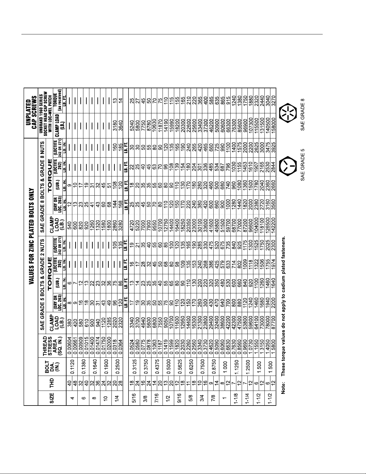
1-3. Torque Chart . . . . . . . . . . . . . . . . . . . . . . . . . . . . . . . . . . . . . . . . . . . . . . . . . . . . . . . . . . . . . . . . . .1-10
3-1. Addco Adjustments. . . . . . . . . . . . . . . . . . . . . . . . . . . . . . . . . . . . . . . . . . . . . . . . . . . . . . . . . . . . . 3-1
3-2. Swing Torque Hub Adjustment. . . . . . . . . . . . . . . . . . . . . . . . . . . . . . . . . . . . . . . . . . . . . . . . . . . . 3-3
3-3. Swing Bearing Bolt Feeler Gauge Check . . . . . . . . . . . . . . . . . . . . . . . . . . . . . . . . . . . . . . . . . . . .3-4
3-4. Swing Bearing Tolerance Measuring Point . . . . . . . . . . . . . . . . . . . . . . . . . . . . . . . . . . . . . . . . . .3-4
3-5. Swing Bearing Tolerance Boom Placement . . . . . . . . . . . . . . . . . . . . . . . . . . . . . . . . . . . . . . . . . . 3-5
3-6. Swing Bearing Torque Sequence . . . . . . . . . . . . . . . . . . . . . . . . . . . . . . . . . . . . . . . . . . . . . . . . . .3-7
3-7. Swing Brake Assembly (Mico) . . . . . . . . . . . . . . . . . . . . . . . . . . . . . . . . . . . . . . . . . . . . . . . . . . . .3-8
3-8. Tilt Switch Adjustment. . . . . . . . . . . . . . . . . . . . . . . . . . . . . . . . . . . . . . . . . . . . . . . . . . . . . . . . . . . 3-9
4-1. Platform Section Replacement . . . . . . . . . . . . . . . . . . . . . . . . . . . . . . . . . . . . . . . . . . . . . . . . . . . . 4-1
4-2. Dimensions of Boom Sections . . . . . . . . . . . . . . . . . . . . . . . . . . . . . . . . . . . . . . . . . . . . . . . . . . . .4-1
4-3. Clamping Wire Ropes . . . . . . . . . . . . . . . . . . . . . . . . . . . . . . . . . . . . . . . . . . . . . . . . . . . . . . . . . . .4-1
4-4. Location and Thickness of Wear Pads . . . . . . . . . . . . . . . . . . . . . . . . . . . . . . . . . . . . . . . . . . . . . .4-2
4-5. Location of Components - Platform Support . . . . . . . . . . . . . . . . . . . . . . . . . . . . . . . . . . . . . . . . . 4-4
4-6. Location of Components - Rotator and Leveling Cylinder . . . . . . . . . . . . . . . . . . . . . . . . . . . . . . .4-4
4-7. Location of Components - Boom Powertrack . . . . . . . . . . . . . . . . . . . . . . . . . . . . . . . . . . . . . . . .4-5
4-8. Boom Assembly Cutaway - S Models - Sheet 1 of 3 . . . . . . . . . . . . . . . . . . . . . . . . . . . . . . . . . . . 4-6
4-9. Boom Assembly Cutaway - S Models - Sheet 2 of 3 . . . . . . . . . . . . . . . . . . . . . . . . . . . . . . . . . . . 4-7
4-10. Boom Assembly Cutaway - S Models - Sheet 3 of 3 . . . . . . . . . . . . . . . . . . . . . . . . . . . . . . . . . . . 4-8
4-11. Disassembly of Sheave Assembly . . . . . . . . . . . . . . . . . . . . . . . . . . . . . . . . . . . . . . . . . . . . . . . . . 4-9
4-12. Disassembly Wire Rope Routing Procedure . . . . . . . . . . . . . . . . . . . . . . . . . . . . . . . . . . . . . . . . .4-9
4-13. Dimension of Sheaves When New . . . . . . . . . . . . . . . . . . . . . . . . . . . . . . . . . . . . . . . . . . . . . . . . .4-10
4-14. Routing Installation of Retract Wire Ropes . . . . . . . . . . . . . . . . . . . . . . . . . . . . . . . . . . . . . . . . . . .4-11
4-15. Reassembly of Components - Boom Powertrack Assembly . . . . . . . . . . . . . . . . . . . . . . . . . . . . . 4-12
4-16. Boom Powertrack Installation . . . . . . . . . . . . . . . . . . . . . . . . . . . . . . . . . . . . . . . . . . . . . . . . . . . . .4-13
4-17. Location of Components - Articulating Jib Boom. . . . . . . . . . . . . . . . . . . . . . . . . . . . . . . . . . . . . .4-14
4-18. Limit Switches Adjustments . . . . . . . . . . . . . . . . . . . . . . . . . . . . . . . . . . . . . . . . . . . . . . . . . . . . . .4-16
4-19. Rotator Assembly (Helac) . . . . . . . . . . . . . . . . . . . . . . . . . . . . . . . . . . . . . . . . . . . . . . . . . . . . . . . .4-18
4-20. Rotary Actuator - Exploded View . . . . . . . . . . . . . . . . . . . . . . . . . . . . . . . . . . . . . . . . . . . . . . . . . .4-19
4-21. Rotary Actuator - Assembly Drawing . . . . . . . . . . . . . . . . . . . . . . . . . . . . . . . . . . . . . . . . . . . . . . .4-20
4-22. SUPERFLEX Terminal Identification . . . . . . . . . . . . . . . . . . . . . . . . . . . . . . . . . . . . . . . . . . . . . . . .4-31
4-23. Wiring Diagram - Single Coil Uni-Directional Flow Control Valve - 1 Axis. . . . . . . . . . . . . . . . . . . 4-32
4-24. Controller Pattern . . . . . . . . . . . . . . . . . . . . . . . . . . . . . . . . . . . . . . . . . . . . . . . . . . . . . . . . . . . . . .4-33
4-25. Calibration Flow Diagram . . . . . . . . . . . . . . . . . . . . . . . . . . . . . . . . . . . . . . . . . . . . . . . . . . . . . . . .4-36
4-26. Testing the SUPERFLEX . . . . . . . . . . . . . . . . . . . . . . . . . . . . . . . . . . . . . . . . . . . . . . . . . . . . . . . . .4-37
4-27. Digisensor Troubleshooting . . . . . . . . . . . . . . . . . . . . . . . . . . . . . . . . . . . . . . . . . . . . . . . . . . . . . .4-38
4-28. Typical SUPERFLEX System Wiring Diagram . . . . . . . . . . . . . . . . . . . . . . . . . . . . . . . . . . . . . . . .4-39
4-29. OPTIMIZER Keypad . . . . . . . . . . . . . . . . . . . . . . . . . . . . . . . . . . . . . . . . . . . . . . . . . . . . . . . . . . . .4-40
5-1. Cylinder Barrel Support. . . . . . . . . . . . . . . . . . . . . . . . . . . . . . . . . . . . . . . . . . . . . . . . . . . . . . . . . . 5-3
5-2. Cap Screw Removal . . . . . . . . . . . . . . . . . . . . . . . . . . . . . . . . . . . . . . . . . . . . . . . . . . . . . . . . . . . .5-3
5-3. Cylinder Rod Support . . . . . . . . . . . . . . . . . . . . . . . . . . . . . . . . . . . . . . . . . . . . . . . . . . . . . . . . . . . 5-3
5-4. Tapered Bushing Removal . . . . . . . . . . . . . . . . . . . . . . . . . . . . . . . . . . . . . . . . . . . . . . . . . . . . . . .5-4
5-5. Gar-Max Bearing Installation. . . . . . . . . . . . . . . . . . . . . . . . . . . . . . . . . . . . . . . . . . . . . . . . . . . . . . 5-4
5-6. Rod Seal Installation . . . . . . . . . . . . . . . . . . . . . . . . . . . . . . . . . . . . . . . . . . . . . . . . . . . . . . . . . . . . 5-5
5-7. Poly-Pak Piston Seal Installation. . . . . . . . . . . . . . . . . . . . . . . . . . . . . . . . . . . . . . . . . . . . . . . . . . .5-5
5-8. Wiper Seal Installation. . . . . . . . . . . . . . . . . . . . . . . . . . . . . . . . . . . . . . . . . . . . . . . . . . . . . . . . . . .5-5
5-9. Installation of Head Seal Kit . . . . . . . . . . . . . . . . . . . . . . . . . . . . . . . . . . . . . . . . . . . . . . . . . . . . . .5-6
5-10. Piston Seal Kit Installation . . . . . . . . . . . . . . . . . . . . . . . . . . . . . . . . . . . . . . . . . . . . . . . . . . . . . . . .5-6
5-11. Tapered Bushing Installation . . . . . . . . . . . . . . . . . . . . . . . . . . . . . . . . . . . . . . . . . . . . . . . . . . . . .5-7
5-12. Seating the Tapered Bearing . . . . . . . . . . . . . . . . . . . . . . . . . . . . . . . . . . . . . . . . . . . . . . . . . . . . .5-7
5-13. Rod Assembly Installation. . . . . . . . . . . . . . . . . . . . . . . . . . . . . . . . . . . . . . . . . . . . . . . . . . . . . . . . 5-8
5-14. Boom Positioning and Support, Cylinder Repair . . . . . . . . . . . . . . . . . . . . . . . . . . . . . . . . . . . . . . 5-9
vi – JLG Lift – 3120794
Page 11

TABLE OF CONTENTS
LIST OF FIGURES (continued)
FIGURE NO. TITLE PAGE NO.
5-15. Articulating Jib Boom Pressure Adjustments . . . . . . . . . . . . . . . . . . . . . . . . . . . . . . . . . . . . . . . . .5-11
5-16. Main Control Valve Pressure Adjustments - Sheet 1 of 2 . . . . . . . . . . . . . . . . . . . . . . . . . . . . . . . . 5-12
5-17. Main Control Valve Pressure Adjustments - Sheet 2 of 2 . . . . . . . . . . . . . . . . . . . . . . . . . . . . . . . . 5-13
5-18. Location of Components - Main Control Valve (Sheet 1) . . . . . . . . . . . . . . . . . . . . . . . . . . . . . . . .5-14
5-19. Location of Components - Main Control Valve (Sheet 2) . . . . . . . . . . . . . . . . . . . . . . . . . . . . . . . .5-15
5-20. Shim Adjustable Charge Relief Valve Components . . . . . . . . . . . . . . . . . . . . . . . . . . . . . . . . . . . .5-17
5-21. Screw Adjustable Charge Relief Valve Components . . . . . . . . . . . . . . . . . . . . . . . . . . . . . . . . . . . 5-17
5-22. Shaft Seal Components . . . . . . . . . . . . . . . . . . . . . . . . . . . . . . . . . . . . . . . . . . . . . . . . . . . . . . . . .5-18
5-23. Installation of Shaft Seal . . . . . . . . . . . . . . . . . . . . . . . . . . . . . . . . . . . . . . . . . . . . . . . . . . . . . . . . .5-18
5-24. Shaft Components . . . . . . . . . . . . . . . . . . . . . . . . . . . . . . . . . . . . . . . . . . . . . . . . . . . . . . . . . . . . .5-19
5-25. Charge Pump Components . . . . . . . . . . . . . . . . . . . . . . . . . . . . . . . . . . . . . . . . . . . . . . . . . . . . . .5-21
5-26. Gauge Port Locations . . . . . . . . . . . . . . . . . . . . . . . . . . . . . . . . . . . . . . . . . . . . . . . . . . . . . . . . . . .5-22
5-27. Plugs/Fittings Size & Torque. . . . . . . . . . . . . . . . . . . . . . . . . . . . . . . . . . . . . . . . . . . . . . . . . . . . . .5-23
6-1. Undercarriage Components . . . . . . . . . . . . . . . . . . . . . . . . . . . . . . . . . . . . . . . . . . . . . . . . . . . . . . 6-1
6-2. Track Carrier Roller - Exploded View . . . . . . . . . . . . . . . . . . . . . . . . . . . . . . . . . . . . . . . . . . . . . . .6-3
6-3. Track Carrier Roller . . . . . . . . . . . . . . . . . . . . . . . . . . . . . . . . . . . . . . . . . . . . . . . . . . . . . . . . . . . . .6-4
6-4. Track Roller - Exploded View . . . . . . . . . . . . . . . . . . . . . . . . . . . . . . . . . . . . . . . . . . . . . . . . . . . . .6-9
6-5. Track Roller . . . . . . . . . . . . . . . . . . . . . . . . . . . . . . . . . . . . . . . . . . . . . . . . . . . . . . . . . . . . . . . . . . .6-10
6-6. Track Link Assembly . . . . . . . . . . . . . . . . . . . . . . . . . . . . . . . . . . . . . . . . . . . . . . . . . . . . . . . . . . . .6-16
6-7. Track Shoe . . . . . . . . . . . . . . . . . . . . . . . . . . . . . . . . . . . . . . . . . . . . . . . . . . . . . . . . . . . . . . . . . . .6-16
6-8. Front Idler Assembly . . . . . . . . . . . . . . . . . . . . . . . . . . . . . . . . . . . . . . . . . . . . . . . . . . . . . . . . . . . .6-19
6-9. Recoil Spring Assembly . . . . . . . . . . . . . . . . . . . . . . . . . . . . . . . . . . . . . . . . . . . . . . . . . . . . . . . . .6-22
6-10. Track Adjuster . . . . . . . . . . . . . . . . . . . . . . . . . . . . . . . . . . . . . . . . . . . . . . . . . . . . . . . . . . . . . . . . .6-28
6-11. Travel Motor. . . . . . . . . . . . . . . . . . . . . . . . . . . . . . . . . . . . . . . . . . . . . . . . . . . . . . . . . . . . . . . . . . . 6-33
6-12. Final Drive . . . . . . . . . . . . . . . . . . . . . . . . . . . . . . . . . . . . . . . . . . . . . . . . . . . . . . . . . . . . . . . . . . . .6-43
6-13. Tooling (J) . . . . . . . . . . . . . . . . . . . . . . . . . . . . . . . . . . . . . . . . . . . . . . . . . . . . . . . . . . . . . . . . . . . .6-56
6-14. Swivel Assembly . . . . . . . . . . . . . . . . . . . . . . . . . . . . . . . . . . . . . . . . . . . . . . . . . . . . . . . . . . . . . . .6-60
7-1. Chassis Service Notes - Sheet 1 of 2 . . . . . . . . . . . . . . . . . . . . . . . . . . . . . . . . . . . . . . . . . . . . . . .7-2
7-2. Chassis Service Notes - Sheet 2 of 2 . . . . . . . . . . . . . . . . . . . . . . . . . . . . . . . . . . . . . . . . . . . . . . .7-3
7-3. Hose Routing - Sheet 1 of 2 . . . . . . . . . . . . . . . . . . . . . . . . . . . . . . . . . . . . . . . . . . . . . . . . . . . . . .7-6
7-4. Hose Routing - Sheet 2 of 2 . . . . . . . . . . . . . . . . . . . . . . . . . . . . . . . . . . . . . . . . . . . . . . . . . . . . . .7-7
8-1. Electrical Components Installation - Sheet 1 . . . . . . . . . . . . . . . . . . . . . . . . . . . . . . . . . . . . . . . . . 8-2
8-2. Electrical Components Installation - Sheet 2 . . . . . . . . . . . . . . . . . . . . . . . . . . . . . . . . . . . . . . . . . 8-3
8-3. Electrical Schematic - Deutz or Isuzu - Sheet 1 . . . . . . . . . . . . . . . . . . . . . . . . . . . . . . . . . . . . . . .8-4
8-4. Electrical Schematic - Deutz or Isuzu - Sheet 2 . . . . . . . . . . . . . . . . . . . . . . . . . . . . . . . . . . . . . . .8-5
8-5. Hydraulic Schematic - Sheet 1 of 4. . . . . . . . . . . . . . . . . . . . . . . . . . . . . . . . . . . . . . . . . . . . . . . . . 8-6
8-6. Hydraulic Schematic - Sheet 2 of 4. . . . . . . . . . . . . . . . . . . . . . . . . . . . . . . . . . . . . . . . . . . . . . . . . 8-7
8-7. Hydraulic Schematic - Sheet 3 of 4. . . . . . . . . . . . . . . . . . . . . . . . . . . . . . . . . . . . . . . . . . . . . . . . . 8-8
8-8. Hydraulic Schematic - Sheet 4 of 4. . . . . . . . . . . . . . . . . . . . . . . . . . . . . . . . . . . . . . . . . . . . . . . . . 8-9
8-9. Hydraulic Schematic w/GFT24 Drive - Sheet 1 of 4 . . . . . . . . . . . . . . . . . . . . . . . . . . . . . . . . . . . .8-10
8-10. Hydraulic Schematic w/GFT24 Drive - Sheet 2 of 4 . . . . . . . . . . . . . . . . . . . . . . . . . . . . . . . . . . . .8-11
8-11. Hydraulic Schematic w/GFT24 Drive - Sheet 3 of 4 . . . . . . . . . . . . . . . . . . . . . . . . . . . . . . . . . . . .8-12
8-12. Hydraulic Schematic w/GFT24 Drive - Sheet 4 of 4 . . . . . . . . . . . . . . . . . . . . . . . . . . . . . . . . . . . .8-13
3120794 – JLG Lift – vii
Page 12

TABLE OF CONTENTS (Continued)
LIST OF TABLES
TABLE NO. TITLE PAGE NO.
1-1 Function Speeds (In Seconds) . . . . . . . . . . . . . . . . . . . . . . . . . . . . . . . . . . . . . . . . . . . . . . . . . . . .1-2
1-2 Torque Requirements . . . . . . . . . . . . . . . . . . . . . . . . . . . . . . . . . . . . . . . . . . . . . . . . . . . . . . . . . . .1-3
1-3 Hydraulic Oil . . . . . . . . . . . . . . . . . . . . . . . . . . . . . . . . . . . . . . . . . . . . . . . . . . . . . . . . . . . . . . . . . . 1-4
1-4 Mobil DTE 13M Specs. . . . . . . . . . . . . . . . . . . . . . . . . . . . . . . . . . . . . . . . . . . . . . . . . . . . . . . . . . . 1-4
1-5 Lubrication Specifications. . . . . . . . . . . . . . . . . . . . . . . . . . . . . . . . . . . . . . . . . . . . . . . . . . . . . . . . 1-4
1-6 Cylinder Specifications . . . . . . . . . . . . . . . . . . . . . . . . . . . . . . . . . . . . . . . . . . . . . . . . . . . . . . . . . . 1-5
1-7 Major Component Weights . . . . . . . . . . . . . . . . . . . . . . . . . . . . . . . . . . . . . . . . . . . . . . . . . . . . . . .1-5
1-8 Critical Stability Weights . . . . . . . . . . . . . . . . . . . . . . . . . . . . . . . . . . . . . . . . . . . . . . . . . . . . . . . . . 1-5
1-9 Lubrication Chart. . . . . . . . . . . . . . . . . . . . . . . . . . . . . . . . . . . . . . . . . . . . . . . . . . . . . . . . . . . . . . .1-9
2-1 Inspection and Maintenance. . . . . . . . . . . . . . . . . . . . . . . . . . . . . . . . . . . . . . . . . . . . . . . . . . . . . .2-2
2-2 Cylinder Drift . . . . . . . . . . . . . . . . . . . . . . . . . . . . . . . . . . . . . . . . . . . . . . . . . . . . . . . . . . . . . . . . . . 2-5
2-3 Inspection and Preventive Maintenance Schedule . . . . . . . . . . . . . . . . . . . . . . . . . . . . . . . . . . . .2-7
3-1 Position Controller Truth Table . . . . . . . . . . . . . . . . . . . . . . . . . . . . . . . . . . . . . . . . . . . . . . . . . . . .3-1
4-1 Adjusting Threshold . . . . . . . . . . . . . . . . . . . . . . . . . . . . . . . . . . . . . . . . . . . . . . . . . . . . . . . . . . . .4-34
4-2 Adjustment Values. . . . . . . . . . . . . . . . . . . . . . . . . . . . . . . . . . . . . . . . . . . . . . . . . . . . . . . . . . . . . .4-35
4-3 Factory Defaults . . . . . . . . . . . . . . . . . . . . . . . . . . . . . . . . . . . . . . . . . . . . . . . . . . . . . . . . . . . . . . .4-35
5-1 Cylinder Head and Tapered Bushing Torque Specifications. . . . . . . . . . . . . . . . . . . . . . . . . . . . . 5-8
5-2 Holding Valve Torque Specifications . . . . . . . . . . . . . . . . . . . . . . . . . . . . . . . . . . . . . . . . . . . . . . .5-8
5-3 Recommended Gauge Size . . . . . . . . . . . . . . . . . . . . . . . . . . . . . . . . . . . . . . . . . . . . . . . . . . . . . .5-16
6-1 Track Carrier Roller Required Tools - Removal and Installation. . . . . . . . . . . . . . . . . . . . . . . . . . .6-1
6-2 Track Carrier Roller Required Tools - Assembly. . . . . . . . . . . . . . . . . . . . . . . . . . . . . . . . . . . . . . .6-5
6-3 Track Roller Required Tools - Removal . . . . . . . . . . . . . . . . . . . . . . . . . . . . . . . . . . . . . . . . . . . . .6-8
6-4 Track Roller Required Tools - Assembly. . . . . . . . . . . . . . . . . . . . . . . . . . . . . . . . . . . . . . . . . . . . .6-11
6-5 Track Roller Required Tools - Removal . . . . . . . . . . . . . . . . . . . . . . . . . . . . . . . . . . . . . . . . . . . . .6-14
6-6 Track Required Tools - Separate . . . . . . . . . . . . . . . . . . . . . . . . . . . . . . . . . . . . . . . . . . . . . . . . . . 6-15
6-7 Track Required Tools - Connect. . . . . . . . . . . . . . . . . . . . . . . . . . . . . . . . . . . . . . . . . . . . . . . . . . . 6-16
6-8 Front Idler Required Tools - Assembly . . . . . . . . . . . . . . . . . . . . . . . . . . . . . . . . . . . . . . . . . . . . . .6-20
6-9 Recoil Spring Required Tools - Disassembly . . . . . . . . . . . . . . . . . . . . . . . . . . . . . . . . . . . . . . . . .6-22
6-10 Recoil Spring Required Tools - Assembly . . . . . . . . . . . . . . . . . . . . . . . . . . . . . . . . . . . . . . . . . . .6-25
6-11 Track Adjuster Required Tools - Assembly. . . . . . . . . . . . . . . . . . . . . . . . . . . . . . . . . . . . . . . . . . .6-29
6-12 Final Drive Sprocket Required Tools - Removal. . . . . . . . . . . . . . . . . . . . . . . . . . . . . . . . . . . . . . .6-30
6-13 Final Drive Sprocket Required Tools - Installation . . . . . . . . . . . . . . . . . . . . . . . . . . . . . . . . . . . . .6-31
6-14 Travel Motor Required Tools - Removal . . . . . . . . . . . . . . . . . . . . . . . . . . . . . . . . . . . . . . . . . . . . .6-32
6-15 Travel Motor Required Tools - Disassembly. . . . . . . . . . . . . . . . . . . . . . . . . . . . . . . . . . . . . . . . . .6-37
6-16 Travel Motor Required Tools - Assembly . . . . . . . . . . . . . . . . . . . . . . . . . . . . . . . . . . . . . . . . . . . . 6-38
6-17 Travel Motor Required Tools - Installation . . . . . . . . . . . . . . . . . . . . . . . . . . . . . . . . . . . . . . . . . . . 6-40
6-18 Final Drive Required Tools - Removal. . . . . . . . . . . . . . . . . . . . . . . . . . . . . . . . . . . . . . . . . . . . . . .6-41
6-19 Final Drive Required Tools - Disassembly . . . . . . . . . . . . . . . . . . . . . . . . . . . . . . . . . . . . . . . . . . . 6-42
6-20 Final Drive Required Tools - Assembly. . . . . . . . . . . . . . . . . . . . . . . . . . . . . . . . . . . . . . . . . . . . . .6-50
6-21 Final Drive Required Tools - Installation . . . . . . . . . . . . . . . . . . . . . . . . . . . . . . . . . . . . . . . . . . . . .6-56
viii – JLG Lift – 3120794
Page 13

SECTION 1 - SPECIFICATIONS
SECTION 1. SPECIFICATIONS
1.1 CAPACITIES
Fuel Tank
39 US. Gallons (147.6 l)
Hydraulic Oil Tank
31 U.S. Gallons (117.3 l) with 10% air space
Hydraulic System (Including Tank)
37.2 U.S. Gallons (140.8 l)
Engine Crankcase
Deutz F4M1011F Diesel w/Filter - 11 quarts (10.5 l)
1.2 COMPONENT DATA
Engine - Diesel (Liquid-Cooled)
Manufacturer/Model- Deutz F4M1011F.
Oil Capacity.
5 Quarts (4.5 l) Cooling System.
11 Quarts (10.5 l) w/Filter.
16 Quarts (15 l) Total Capacity.
Low RPM - 1800.
Swing System
Swing Motor Displacement - 4.62 cu. in. (75 cm3]).
Swing Brake - Automatic spring applied hydraulically
released disc brakes.
Swing Hub Ratio - 50:1.
Hydraulic Gear Pump. (at 1800 RPM)
7.9 GPM (29.90 lpm).
Pump Displacement - 1.02 cu. in. (16 cm3]).
Clockwise Rotation.
Auxiliary Power Pump
2.6 GPM (9.84 lpm) @ 1200 PSI. (82.7 BAR.
Pump Displacement - .244 cu. in. (14 cm3]).
DC Motor.
Clockwise Rotation.
Hydraulic Filter - In-line.
Return - Bypass Type.
10 Microns Absolute.
Charge.
10 Microns Absolute.
Hydraulic Strainers (In Tank).
High RPM - 2800.
Alternator - 60 Amp, belt drive.
Battery - 1000 Cold Cranking Amps, 210 Minutes
ReserveCapacity, 12 VDC.
Fuel Consumption.
Low RPM - 1.90 GPH (7.19 lph).
High RPM - 2.50 GPH (9.46 lph).
Horsepower - 65 @ 3000 RPM, full load.
Engine - Diesel. (Water-Cooled)
30 Microns.
3120794 – JLG Lift – 1-1
Page 14

SECTION 1 - SPECIFICATIONS
1.3 PERFORMANCE DATA
Travel Speed
1.6 MPH (2.6 Km/hr.)
Trav el Speed - Out o f Tr a n s p o r t
0.4 MPH (0.6 Km/hr.)
Gradeability.
55%
Turning Radius (Outside)
8 ft. (2.4 m)
Turning Radius (Inside)
0
Boom Elevation
600SC - +60 ft. 2 13/16 in. (18.36 m)
-6 ft. 1 11/16 in. (1.87 m)
600SCJ - +60 ft. 5 3/4 in. (18.43 m)
-9 ft. 9 3/16 in. (2.98 m)
660SCJ - +66 ft. 7 5/8 in. (20.31 m)
-11 ft. 5 1/4 in. (3.49 m)
Machine Weight approximately
Steel Track - 25,900 lbs. (11,748 kg)
Rubber Track - 26,860 lbs. (12,184 kg)
Machine Height (Stowed)
Steel Track - 8’4" (2.54 m)
Rubber Track - 8’6" (2.59 m)
Machine Length (Stowed)
35’ 6" (10.8 m)
Machine Width
8 ft. (2.4 m)
1.4 FUNCTION SPEEDS
Table 1-1. Function Speeds (In Seconds)
Function Speed
Lift Up 46-60
Lift Down 33-43
Swing Right & Left* 79-101
Te le sc o pe In 2 2- 33
Te le sc o pe Ou t 5 0- 67
Platform Rotate Right & Left** 16-25
Jib Up 22-34
Jib Down 16-26
Drive (Forward & Reverse) 85-90
Drive Out of Transpor t (Forward & Reverse) 80-85
*Max 10% Difference Between Left & Right
**Max 15% Difference Between Left & Right
Machine Orientation When Doing Speed
Te st s
Lift: Telescope Retracted. Lift Up, Record Time, Lift Down,
Record Time.
Swing: Boom at Full Elevation. Telescope Retracted.
Swing the Turntable off center and stop. Swing the opposite direction ana start the test wen the turntable is centered up. This eliminates ramp up and down on the
controller affecting times.
Te l es c o pe : Boom at Full Elevation; Telescope Retracted;
Telescope Out, Record Time. Telescope In, Record Time.
Tracking: Test to be done on a gravelled level surface.
Position the machine driving at high speed at a reference
point. (No steer correction). Results should be 4 to 6
ft.(1.2 to 1.8 m) tracking error at 200 ft. (60.9 m).
Drive: Test should be done on a graveled level surface.
Drive select switch should be set at High Speed. Start
approx. 10 ft. from starting point so that the unit is at maximum speed when starting the test. Results should be
recorded for a 200 ft. (60.9 m) course. Drive Forward,
Record Time. Drive Reverse, Record Time.
Drive (Out of Transport): Test should be done on a graveled level surface. Drive select switch should be set at
Low Engine, Low Drive (The platform speed knob control,
if equipped, could be selected to the creep speed to simulate the boom above horizontal). Results should be
recorded for a 50 ft. (15.2 m) course. Drive Forward,
Record Time. Drive Reverse, Record Time.
1-2 – JLG Lift – 3120794
Page 15

SECTION 1 - SPECIFICATIONS
Platform Rotate: Platform level and completely rotated
one direction. Rotate the opposite direction, Record Time.
Rotate the other direction, Record Time.
Articulating Jib: Platform level and centered with the
boom. Start with the Jib down. Jib Up, Record Time. Jib
Down, Record Time.
Te s t No te s
1. Stop watch should be started with the function, not
with the controller or switch.
2. All speed tests are run from the platform. These
speeds do not reflect the ground control operation.
3. The platform speed knob control must be at full
speed (turned clockwise completely).
4. Function speeds may vary due to cold, thick hydraulic oil. Test should be run with the oil temperature
above 100° F (38° C).
5. Some flow control functions may not work with the
speed knob clicked into the creep position.
1.5 TORQUE REQUIREMENTS
Table 1-2. Torque Requirements
Description Torque Value ( D r y) Interval Hours
Bearing To Chassis See Note 50/600*
1.6 LUBRICATION
Deutz F4M1011F Engine
Single Viscosity Oil (CD-SE, CD-SF).
When Outside Temperature is
Consistently
-20°F. to +25°F. (-29°C. to +4°C.) *10W
+5°F. to +50°F. (+15°C. to +10°C.) 20W-20
+40°F. to +85°F. (+4°C. to +30°C.) 30
Above 75°F. (24°C.) 40
Multi Viscosity Oil (CD-SE, CD-SF)
*This viscosity can be used at colder temperatures with
engine oil preheating.
When Outside
Te m pe r at u re is
Consistently
-40°F. to +75°F. (-40°C. to
+24°C.)
-15°F. to +70°F. (-26°C. to
+21°C.)
-15°F. to +85°F. (-26°C. to
+30°C.)
Above -5°F. (-21°C.) 15W-40
-5°F. to +75°F. (-21°C. to
+24°C.)
*This viscosity can be used at colder temperatures with
engine oil preheating.
Use SAE Viscosity
Number
Use SAE Viscosity Number
*5W-30 (Synthetic)
10W-30
10W-40
15W-30
Bearing To Turntable See Note 50/600*
Wire Rope 15 ft.lbs.
(20 Nm)
M16 Travel motor
mounting bolts
M20 Final Drive
mounting bolts
M20 Track roller
mounting bolts
M24 Carrier roller
mounting bolts
*Check swing bearing bolts for security after first 50 hours of operation and every 600 hours thereaf ter. (See paragraph on Swing Bearing
in Section 2.)
NOTE: When maintenance becomes necessary or a fas-
tener has loosened, refer to the Torque Chart to
determine proper torque value.
175 ±30 ft.lbs.
(240±40 Nm)
390 ±50 ft.lbs.
(530±70 Nm)
340 ±44 ft.lbs.
(460±60 Nm)
600 ±70 ft.lbs.
(800±100 Nm)
150
As
required
As
required
As
required
As
required
NOTE: Crankcase oil should be MIL-L2104B/MIL-L2104C or
have properties of API classification CC/CD grades.
3120794 – JLG Lift – 1-3
Page 16

SECTION 1 - SPECIFICATIONS
Hydraulic Oil
Table 1-3. Hydraulic Oil
HYDRAULIC SYSTEM
OPERATING TEMPERATURE
RANGE
+0° to +180° F (-18° C to +83°
C)
+0° F to +210° F (-18° C to +99°
C)
+50° F to +210° F (+10° C to
+210° C)
NOTE: Hydraulic oils must have anti-wear qualities at least
to API Service Classification GL-3, and sufficient
chemical stability for mobile hydraulic system service. JLG Industries recommends Mobilfluid 424
hydraulic oil, which has an SAE viscosity index of
152 .
NOTE: When temperatures remain below 20° F (-7 degre es
C), JLG Industries recommends the use of Mobil
DTE 13M.
Table 1-4. Mobil DTE 13M Specs
ISO Viscosity Grade #32
Specific Gravity 0.877
Pour Point, Max -40°F (-40°C)
Flash Point, Min. 330°F (166°C)
Viscosity
at 40° C 33cSt
at 100° C 6.6 cSt
at 100° F 169 SUS
at 210° F 48 SUS
cp at -20° F 6,200
Viscosity Index 140
SAE VISCOSITY GRADE
10W
10W-20, 10W-30
20W-20
Lubrication Specifications
Table 1-5. Lubrication Specifications
KEY SPECIFICATIONS
MPG
EPGL
HO
EO
Multipurpose Grease having a minimum
dripping point of 350° F. Excellent water
resistance and adhesive qualities, and
being of extreme pressure type.
(Timken OK 40 pounds minimum.)
Extreme Pressure Gear Lube (oil) meeting
API service classification GL-5 or MIL-Spec
MIL-L-2105
Hydraulic Oil. API service classification GL3, e.g. Mobilfluid 424.
Engine (crankcase) Oil. Gas - API SF, SH,
SG class, MIL-L-2104. Diesel - API CC/CD
class, MIL-L-2104B/MIL-L-2104C.
NOTE: Refer to Lubrication Chart, for specific lubrication
procedures.
1.7 PRESSURE SETTINGS
Main Relief - 3000 PSI (206.85 Bar).
Upper Boom Lift Down - 1500 PSI (103.4 Bar).
Swing - 1700 PSI (117.2 Bar).
Platform Level Forward - 2800 PSI (193.06 Bar).
Backward - 1800 PSI (124.11 Bar).
Articulating Jib Boom Up - 1500 PSI (103 Bar).
Down - 1200 PSI (82.7 Bar).
Aside from JLG recommendations, it is not advisable to
mix oils of different brands or types, as they may not contain the same required additives or be of comparable viscosities. If use of hydraulic oil other than Mobilfluid 424 is
desired, contact JLG Industries for proper recommendations.
1-4 – JLG Lift – 3120794
Page 17
SECTION 1 - SPECIFICATIONS
1.8 CYLINDER SPECIFICATIONS
Table 1-6. Cylinder Specifications
DESRIPTON BORE STROKE ROD DIA.
600SJ 660SJ 600S 600SJ 660SJ 600S 600SJ 660SJ 600S
Lift 6.00
Tel e sc o pe 3. 5
Master 3.5
Slave Level 3.5
Lift (Articulating Jib
Boom)
(152.4)
(88.9)
(88.9)
(88.9)
(76.2)
3
6.00
(152.4)
3.5
(88.9)
3.5
(88.9)
3.5
(88.9)
3
(76.2)
6.00
(152.4)
3.5
(88.9)
3
(76.2)
3
(76.2)
N/A 25.5
44.6875
(1135.1)
143.1875
(3637)
13.0625
(331.8)
13.0625
(331.8)
(647.7)
44.6875
(1135.1)
168.4375
(4278.3)
13.0625
(331.8)
13.0625
(331.8)
25.5
(647.7)
44.6875
(1135.1)
177.75
(4514.9)
8.5
(215.9)
8.5
(215.9)
N/A 1.5
3
(76.2)
2.5
(63.5)
1.5
(38.1)
1.5
(38.1)
(38.1)
(76.2)
2.5
(63.5)
1.5
(38.1)
1.5
(38.1)
1.5
(38.1)
1.9 MAJOR COMPONENT WEIGHTS
Table 1-7. Major Component Weights
600SJ 660SJ 600S
LB. KG. LB. KG. LB. KG.
Platform Control Console 250 113 250 113 250 113
Platform Level Cylinder 60 27 60 27 46 21
Main Boom (Includes Lift Cyl., Rotator, and Support)
Turntable Complete (including engine) 7915 3590 9065 4112 7315 3318
3483 1580 3783 1716 3527 1600
3
3
(76.2)
2.5
(63.5)
1.5
(38.1)
1.5
(38.1)
N/A
1.10 CRITICAL STABILITY WEIGHTS
DO NOT REPLACE ITEMS CRITICAL TO STABILITY WITH ITEMS
OF DIFFERENT WEIGHT OR SPECIFICATION (FOR EXAMPLE: BATTERIES, FILLED TIRES, COUNTERWEIGHT, ENGINE & PLATFORM)
DO NOT MODIFY UNIT IN ANY WAY TO AFFECT STABILITY.
Table 1-8. Critical Stability Weights
600SJ 660SJ 600S
LB. KG. LB. KG. LB. KG.
Engine Ford 460 209 460 209 460 209
Platform 6 ft. (1.83 M) 205 93 205 93 205 93
8 ft. (2.44 M) 230 105 230 105 230 105
3120794 – JLG Lift – 1-5
Page 18
SECTION 1 - SPECIFICATIONS
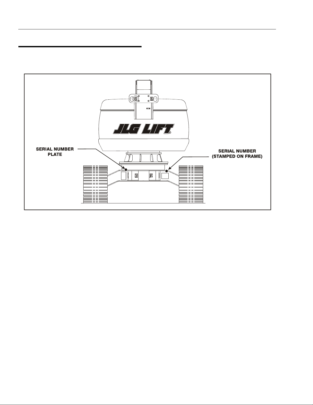
Figure 1-1. Serial Number Locations
1.11 SERIAL NUMBER LOCATIONS
A serial number plate is affixed to the left rear side of the
frame. If the serial number plate is damaged or missing,
the machine serial number is stamped on the left side of
the frame.
1-6 – JLG Lift – 3120794
Page 19

SECTION 1 - SPECIFICATIONS
This page left blank intentionally.
3120794 – JLG Lift – 1-7
Page 20
SECTION 1 - SPECIFICATIONS
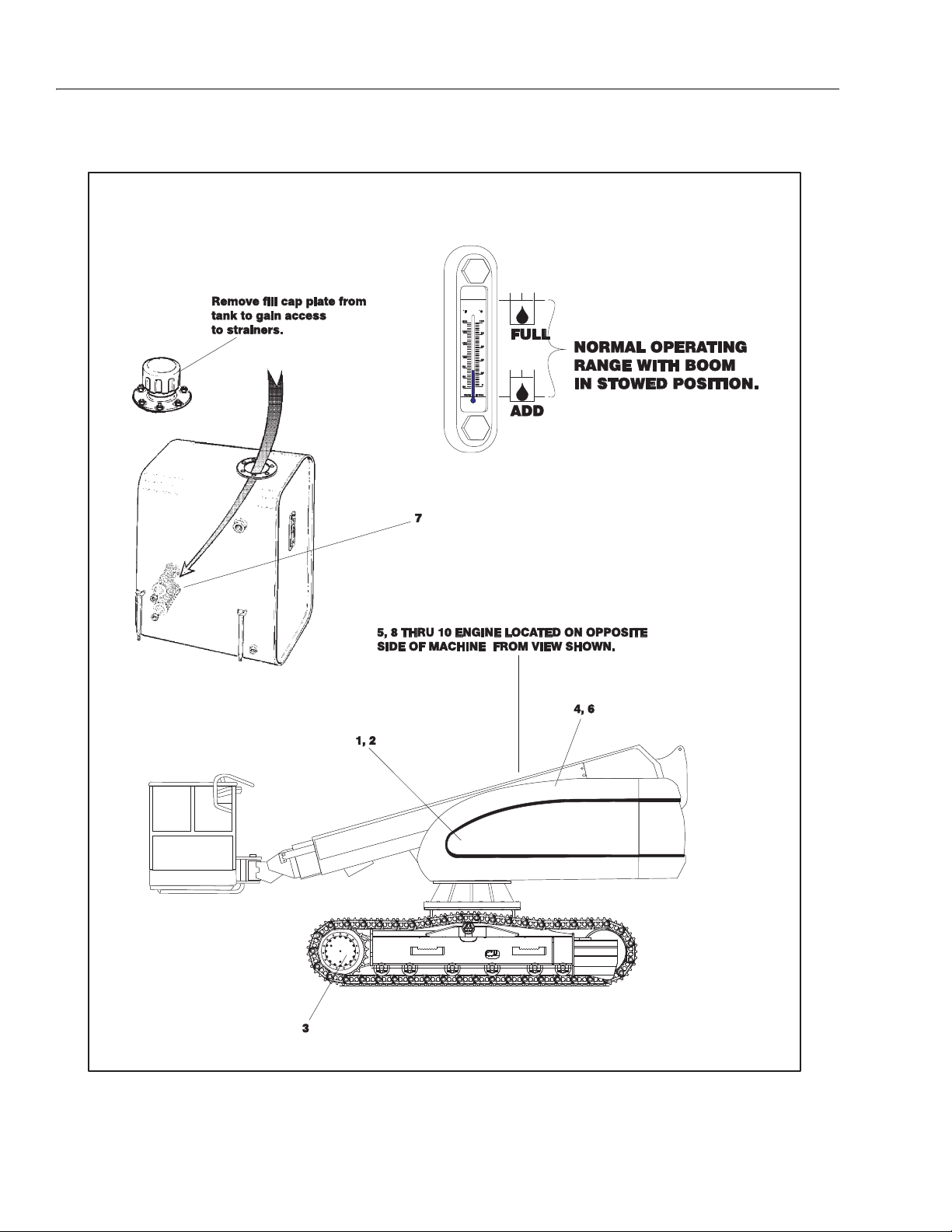
Figure 1-2. Lubrication Point Location
1-8 – JLG Lift – 3120794
Page 21

Components
Lubrication
Swing Bearing
1
Swing Drive Hub
2
Final Drive Hub
3
Hydraulic Return Filter
4
Hydraulic Charge Filter
5
Hydraulic Oil
6
Suction Strainers (in tan k)
7
SECTION 1 - SPECIFICATIONS
Table 1-9. Lubrication Chart
Interval Hours
Number/Type
Lube Points
2 Grease Fittings A/R MPG X Remote Access
Level/Fill Plug 17 oz. (1/2 Full) EPGL X Check level ever y 150 hrs/change 1200
Level/Fill Plug 2.1 gal. (1/2 Full) EPGL X Check level every 150 hrs/change 1200
N/A N/A N/A X Change after first 50 hrs. and every 300
N/A N/A N/A X Change after first 50 hrs. and every 300
Fill Cap 30.6 gal. Tank
2 N/A N/A X Remove and clean at time of hydraulic oil
Capacity Lube
32.7 gal. System
3
Months
150 hrs
HO X Check level daily/change 1200 hours
6
Months
300 hrs
1 Year
600 hrs
2 Years
1200
hrs
hours
hours
hrs. thereafte r or as indicated by Condition
Indicator.
hrs. thereafte r or as indicated by Condition
Indicator.
change.
Comments
Engines
Oil Change w/Filter - Deutz
8
Fuel Filter - Deutz
9
Air Filter - Deutz
1
0
NOTES: KEY TO LUBRICANTS
Lubrication intervals are based on ma chine operation under
normal conditions. For machines used in multi shift operations
and/or exposed to hostile en vironments or conditions, lubrication frequencies must be increased accordingly.
Fill Cap/Spin-on Ele-
ment
Replaceable Element N/A N/A X
Replaceable Element N/A N/A X Or as indicated by Condition Indicator.
11 Quarts Crank-
case
**5 Quarts Cooler
** When changing oil in the Deutz oil cooled engine, drain both the crankcase and the cooler. When refilling it is acceptable to overfill the crankcase
(16 qts., capacity of both crankcase and cooler combined). Star t engine,
allow the engine to run until the thermostat opens (approximately 221
de g re e s F) c oo l er w il l fi l l up w it h in m in u te s ; s h ut d o wn a nd w ai t fo r ap p ro x imately two minutes. Check oil level, fill oil to max marking on t he dipstick.
EO X Check level daily/Change every 1000
hours or one year, whichever comes first.
Adjust final oil level by mark on dipstick.
EO
Engine Oil
EPGL
Extreme Pressure Gear Lube
Hydraulic Fluid (Mobil #424 or equiva-
HO
lent)
MPG
Multi-Purpose Grease
3120794 – JLG Lift – 1-9
Page 22
SECTION 1 - SPECIFICATIONS
Figure 1-3. Torque Chart
1-10 – JLG Lift – 3120794
Page 23

SECTION 2. GENERAL
SECTION 2 - GENERAL
2.1 MACHINE PREPARATION, INSPECTION, AND MAINTENANCE
General
This section provides the necessary information needed
by those personnel that are responsible to place the
machine in operation readiness and maintain its safe
operating condition. For maximum service life and safe
operation, ensure that all the necessary inspections and
maintenance have been completed before placing the
machine into service.
Preparation, Inspection, and Maintenance
It is important to establish and conform to a comprehensive inspection and preventive maintenance program. The
following table outlines the periodic machine inspections
and maintenance recommended by JLG Industries, Inc.
Consult your national, regional, or local regulations for further requirements for aerial work platforms. The frequency
of inspections and maintenance must be increased as
environment, severity and frequency of usage requires.
Pre-Start Inspection
It is the User’s or Operator’s primary responsibility to perform a Pre-Start Inspection of the machine prior to use
daily or at each change of operator. Reference the Operator’s and Safety Manual for completion procedures for the
Pre-Start Inspection. The Operator and Safety Manual
must be read in its entirety and understood prior to performing the Pre-Start Inspection.
Pre-Delivery Inspection and Frequent
Inspection
The Pre-Delivery Inspection and Frequent Inspection shall
be performed by a qualified JLG equipment mechanic.
JLG Industries, Inc. recognizes a qualified JLG equipment
mechanic as a person who, by possession of a recognized degree, certificate, extensive knowledge, training, or
experience, has successfully demonstrated the ability and
proficiency to service, repair, and maintain the subject
JLG product model.
The Pre-Delivery Inspection and Frequent Inspection procedures are performed in the same manner, but at different times. The Pre-Delivery Inspection shall be performed
prior to each sale, lease, or rental delivery. The Frequent
Inspection shall be accomplished for each machine in service for 3 months or 150 hours (whichever comes first);
out of service for a period of more than 3 months; or when
purchased used. The frequency of this inspection must be
increased as environment, severity and frequency of
usage requires.
Reference the JLG Pre-Delivery and Frequent Inspection
Form and the Inspection and Preventative Maintenance
Schedule for items requiring inspection during the performance of these inspections. Reference the appropriate
areas of this manual for servicing and maintenance procedures.
Annual Machine Inspection
The Annual Machine Inspection must be performed by a
Factory-Certified Service Technician on an annual basis,
no later than thirteen (13) months from the date of the
prior Annual Machine Inspection. JLG Industries, Inc. recognizes a Factory-Certified Service Technician as a person who has successfully completed the JLG Service
Training School for the subject JLG product model. Reference the machine Service and Maintenance Manual and
appropriate JLG inspection form for performance of this
inspection.
Reference the JLG Annual Machine Inspection Form and
the Inspection and Preventative Maintenance Schedule for
items requiring inspection during the performance of this
inspection. Reference the appropriate areas of this manual for servicing and maintenance procedures.
For the purpose of receiving safety-related bulletins, it is
important that JLG Industries, Inc. has updated ownership
information for each machine. When performing each
Annual Machine Inspection, notify JLG Industries, Inc. of
the current machine ownership.
Preventative Maintenance
In conjunction with the specified inspections, maintenance shall be performed by a qualified JLG equipment
mechanic. JLG Industries, Inc. recognizes a qualified JLG
equipment mechanic as a person who, by possession of a
recognized degree, certificate, extensive knowledge, training, or experience, has successfully demonstrated the
ability and proficiency to service, repair, and maintain the
subject JLG product model.
Reference the Preventative Maintenance Schedule and
the appropriate areas of this manual for servicing and
maintenance procedures. The frequency of service and
maintenance must be increased as environment, severity
and frequency of usage requires.
3120794 – JLG Lift – 2-1
Page 24

SECTION 2 - GENERAL
Table 2-1. Inspection and Maintenance
Ty pe Fr eq u en cy
Pre-Start Inspec-
tion
Pre-Delivery
Inspection
Frequent Inspec-
tion
Annual Machine
Inspection
Preventative
Maintenance
Annually, no later than 13 months from the
At interval s as specified in the Service and
Prior to use each day; or
At each Operator change.
Prior to each sale, lease, or
rental delivery.
In service for 3 months or 150 hours,
whichever comes first; or
Out of service for a period of mo re than 3
months; or
Purchased used.
date of the prior inspection.
Maintenance Manual.
2.2 SERVICE AND GUIDELINES
General
The following information is provided to assist you in the
use and application of servicing and maintenance procedures contained in this book.
Safety and Workmanship
Your safety, and that of others, is the first consideration
when engaging in the maintenance of equipment. Always
be conscious of weight. Never attempt to move heavy
parts without the aid of a mechanical device. Do not allow
heavy objects to rest in an unstable position. When raising
a portion of the equipment, ensure that adequate support
is provided.
Cleanliness
1. The most important single item in preserving the
long service life of a machine is to keep dirt and foreign materials out of the vital components. Precautions have been taken to safeguard against this.
Shields, covers, seals, and filters are provided to
keep air, fuel, and oil supplies clean; however, these
items must be maintained on a scheduled basis in
order to function properly.
Primary
Responsibility
User or Operator User or Operator Operator and Safety Manual
Owner, Dealer, or User Qualified JLG
Owner, Dealer, or User Qualified JLG
Owner, Dealer, or User Factory-Cer tified
Owner, Dealer, or User Qualified JLG
2. At any time when air, fuel, or oil lines are disconnected, clear adjacent areas as well as the openings
and fittings themselves. As soon as a line or component is disconnected, cap or cover all openings to
prevent entry of foreign matter.
3. Clean and inspect all parts during servicing or maintenance, and assure that all passages and openings
are unobstructed. Cover all parts to keep them
clean. Be sure all parts are clean before they are
installed. New parts should remain in their containers until they are ready to be used.
Service
Qualification
Mechanic
Mechanic
Service Technician
Mechanic
Reference
Service and Maintenance
Manual and applicable JLG
inspection form.
Service and Maintenance
Manual and applicable JLG
inspection form.
Service and Maintenance
Manual and applicable JLG
inspection form.
Service and Maintenance
Manual
Components Removal and Installation
1. Use adjustable lifting devices, whenever possible, if
mechanical assistance is required. All slings (chains,
cables, etc.) should be parallel to each other and as
near perpendicular as possible to top of part being
lifted.
2. Should it be necessary to remove a component on
an angle, keep in mind that the capacity of an eyebolt or similar bracket lessens, as the angle between
the supporting structure and the component
becomes less than 90 degrees.
3. If a part resists removal, check to see whether all
nuts, bolts, cables, brackets, wiring, etc., have been
removed and that no adjacent parts are interfering.
2-2 – JLG Lift – 3120794
Page 25

SECTION 2 - GENERAL
Component Disassembly and Reassembly
When disassembling or reassembling a component, complete the procedural steps in sequence. Do not partially
disassemble or assemble one part, then start on another.
Always recheck your work to assure that nothing has been
overlooked. Do not make any adjustments, other than
those recommended, without obtaining proper approval.
Pressure-Fit Parts
When assembling pressure-fit parts, use an anti-seize or
molybdenum disulfide base compound to lubricate the
mating surface.
Bearings
1. When a bearing is removed, cover it to keep out dirt
and abrasives. Clean bearings in nonflammable
cleaning solvent and allow to drip dry. Compressed
air can be used but do not spin the bearing.
2. Discard bearings if the races and balls (or rollers)
are pitted, scored, or burned.
3. If bearing is found to be serviceable, apply a light
coat of oil and wrap it in clean (waxed) paper. Do not
unwrap reusable or new bearings until they are
ready to install.
4. Lubricate new or used serviceable bearings before
installation. When pressing a bearing into a retainer
or bore, apply pressure to the outer race. If the bearing is to be installed on a shaft, apply pressure to the
inner race.
Gaskets
Check that holes in gaskets align with openings in the
mating parts. If it becomes necessary to hand-fabricate a
gasket, use gasket material or stock of equivalent material
and thickness. Be sure to cut holes in the right location, as
blank gaskets can cause serious system damage.
2. Unless specific torque requirements are given within
the text, standard torque values should be used on
heat-treated bolts, studs, and steel nuts, in accordance with recommended shop practices. (See
Torque Chart Section 1.)
Hydraulic Lines and Electrical Wiring
Clearly mark or tag hydraulic lines and electrical wiring, as
well as their receptacles, when disconnecting or removing
them from the unit. This will assure that they are correctly
reinstalled.
Hydraulic System
1. Keep the system clean. If evidence of metal or rubber particles are found in the hydraulic system, drain
and flush the entire system.
2. Disassemble and reassemble parts on clean work
surface. Clean all metal parts with non-flammable
cleaning solvent. Lubricate components, as
required, to aid assembly.
Lubrication
Service applicable components with the amount, type,
and grade of lubricant recommended in this manual, at
the specified intervals. When recommended lubricants are
not available, consult your local supplier for an equivalent
that meets or exceeds the specifications listed.
Battery
Clean battery, using a non-metallic brush and a solution of
baking soda and water. Rinse with clean water. After
cleaning, thoroughly dry battery and coat terminals with
an anti corrosion compound.
Lubrication and Servicing
Components and assemblies requiring lubrication and
servicing are shown in the Lubrication Chart in Section 1.
Bolt Usage and Torque Application
1. Use bolts of proper length. A bolt which is too long
will bottom before the head is tight against its related
part. If a bolt is too short, there will not be enough
thread area to engage and hold the part properly.
When replacing bolts, use only those having the
same specifications of the original, or one which is
equivalent.
3120794 – JLG Lift – 2-3
Page 26

SECTION 2 - GENERAL
2.3 LUBRICATION AND INFORMATION
Hydraulic System
1. The primary enemy of a hydraulic system is contamination. Contaminants enter the system by various
means, e.g., using inadequate hydraulic oil, allowing
moisture, grease, filings, sealing components, sand,
etc., to enter when performing maintenance, or by
permitting the pump to cavitate due to insufficient
system warm-up or leaks in the pump supply (suction) lines.
2. The design and manufacturing tolerances of the
component working parts are very close, therefore,
even the smallest amount of dirt or foreign matter
entering a system can cause wear or damage to the
components and generally results in faulty operation. Every precaution must be taken to keep
hydraulic oil clean, including reserve oil in storage.
Hydraulic system filters should be checked,
cleaned, and/or replaced as necessary, at the specified intervals required in the Lubrication Chart in
Section 1. Always examine filters for evidence of
metal particles.
3. Cloudy oils indicate a high moisture content which
permits organic growth, resulting in oxidation or corrosion. If this condition occurs, the system must be
drained, flushed, and refilled with clean oil.
4. It is not advisable to mix oils of different brands or
types, as they may not contain the same required
additives or be of comparable viscosities. Good
grade mineral oils, with viscosities suited to the
ambient temperatures in which the machine is operating, are recommended for use.
NOTE: Metal particles may appear in the oil or filters of new
machines due to the wear-in of meshing components.
Hydraulic Oil
1. Refer to Section 1 for recommendations for viscosity
ranges.
3. The only exception to the above is to drain and fill
the system with Mobil DTE 13 oil or its equivalent.
This will allow start up at temperatures down to -20
degrees F (-29 degrees C). However, use of this oil
will give poor performance at temperatures above
120 degrees F (49 degrees C). Systems using DTE
13 oil should not be operated at temperatures above
200 degrees F (94 degrees C) under any condition.
Changing Hydraulic Oil
1. Use of any of the recommended crankcase or
hydraulic oils eliminates the need for changing the
oil on a regular basis. However, filter elements must
be changed after the first 50 hours of operation and
every 300 hours thereafter. If it is necessary to
change the oil, use only those oils meeting or
exceeding the specifications appearing in this manual. If unable to obtain the same type of oil supplied
with the machine, consult local supplier for assistance in selecting the proper equivalent. Avoid mixing petroleum and synthetic base oils. JLG
Industries recommends changing the hydraulic oil
annually.
2. Use every precaution to keep the hydraulic oil clean.
If the oil must be poured from the original container
into another, be sure to clean all possible contaminants from the service container. Always clean the
mesh element of the filter and replace the cartridge
any time the system oil is changed.
3. While the unit is shut down, a good preventive maintenance measure is to make a thorough inspection
of all hydraulic components, lines, fittings, etc., as
well as a functional check of each system, before
placing the machine back in service.
Lubrication Specifications
Specified lubricants, as recommended by the component
manufacturers, are always the best choice, however,
multi-purpose greases usually have the qualities which
meet a variety of single purpose grease requirements.
Should any question arise, regarding the use of greases in
maintenance stock, consult your local supplier for evaluation. Refer to Section 1 for an explanation of the lubricant
key designations appearing in the Lubrication Chart.
2. JLG recommends Mobilfluid 424 hydraulic oil, which
has an SAE viscosity of 10W-30 and a viscosity
index of 152.
NOTE: Start-up of hydraulic system with oil temperatures
below -15 degrees F (-26 degrees C) is not recommended. If it is necessary to start the system in a
sub-zero environment, it will be necessary to heat
the oil with a low density, 100VAC heater to a minimum temperature of -15 degrees F (-26 degrees C).
2-4 – JLG Lift – 3120794
Page 27

SECTION 2 - GENERAL
2.4 CYLINDER DRIFT TEST
Maximum acceptable cylinder drift is to be measured
using the following methods.
Platform Drift
Measure the drift of the platform to the ground. Lower
booms (if equipped) slightly elevated, upper boom fully
extended with the rated load in the platform and power off.
Maximum allowable drift is 2 inches (5 cm) in 10 minutes.
If the machine does not pass this test, proceed with the
following.
Cylinder Drift
Table 2-2. Cylinder Drift
Cylinder Bore Diameter
inches mm inches mm
3 76.2 0.026 0.66
3.5 89 0.019 0.48
4 101.6 0.015 0.38
5 127 0.009 0.22
6 152.4 0.006 0.15
7 177.8 0.005 0.13
8 203.2 0.0038 0.10
9 228.6 0.0030 0.08
Drift is to be measured at the cylinder rod with a calibrated
dial indicator. The cylinder oil must be at ambient temperature and temperature stabilized.
The cylinder must have the normal load, which is the normal platform load applied.
If the cylinder passes this test, it is acceptable.
NOTE: This information is based on 6 drops per minute cyl-
inder leakage.
Max. Acceptable Drift
in 10 Minutes
2.5 PINS AND COMPOSITE BEARING REPAIR GUIDELINES
Filament wound bearings.
1. Pinned joints should be disassembled and
inspected if the following occurs:
a. Excessive sloppiness in joints.
b. Noise originating from the joint during operation.
2. Filament wound bearings should be replaced if any
of the following is observed:
a. Frayed or separated fibers on the liner surface.
b. Cracked or damaged liner backing.
c. Bearings that have moved or spun in their hous-
ing.
d. Debris embedded in liner surface.
3. Pins should be replaced if any of the following is
observed (pin should be properly cleaned prior to
inspection):
a. Detectable wear in the bearing area.
b. Flaking, pealing, scoring, or scratches on the pin
surface.
c. Rusting of the pin in the bearing area.
4. Re-assembly of pinned joints using filament wound
bearings.
a. Housing should be blown out to remove all dirt
and debris...bearings and bearing housings
must be free of all contamination.
b. Bearing / pins should be cleaned with a solvent
to remove all grease and oil...filament wound
bearing are a dry joint and should not be lubricated.
c. Pins should be inspected to ensure it is free of
burrs, nicks, and scratches which would damage the bearing during installation and operation.
3120794 – JLG Lift – 2-5
Page 28

SECTION 2 - GENERAL
2.6 WELDING ON JLG EQUIPMENT
NOTE: This instruction applies to repairs, or modifications to
the machine and to welding performed from the
machine on an external structure, or component,
Do the Following When Welding on JLG
Equipment
• Disconnect the battery.
• Disconnect the moment pin connection (where fitted)
• Ground only to structure being welded.
Do NOT Do the Following When Welding on
JLG Equipment
• Ground on frame and weld on any other area than the
chassis.
• Ground on turntable and weld on any other area than
the turntable.
• Ground on the platform/support and weld on any other
area than the platform/support.
• Ground on a specific boom section and weld on any
other area than that specific boom section.
• Allow pins, wear pads, wire ropes, bearings, gearing,
seals, valves, electrical wiring, or hoses to be between
the grounding position and the welded area.
FAILURE TO COMPLY WITH THE ABOVE REQUIREMENTS MAY
RESULT IN COMPONENT DAMAGE (I.E. ELECTRONIC MODULES,
SWING BEARING, COLLECTOR RING, BOOM WIRE ROPES ETC.)
2.7 APPLYING SILICONE DIELECTRIC COMPOUND TO ELECTRICAL CONNECTIONS
Silicone Dielectric Compound must be used on all electrical connections for the following reasons:
• To prevent oxidation at the mechanical joint between
male and female pins.
• To prevent electrical malfunction caused by low level
conductivity between pins when wet.
Use the following procedure to apply Silicone Dielectric
Compound to the electrical connectors. This procedure
applies to all plug connections not enclosed in a box. Silicone grease should not be applied to connectors with
external seals.
1. To prevent oxidation, silicone grease must be
packed completely around male and female pins on
the inside of the connector prior to assembly. This is
most easily achieved by using a syringe.
NOTE: Over a period of time, oxidation increases electrical
resistance at the connection, eventually causing circuit failure.
2. To prevent shorting, silicone grease must be packed
around each wire where they enter the outside of the
connector housing. Also, silicone grease must be
applied at the joint where the male and female connectors come together. Any other joints (around
strain reliefs, etc.) where water could enter the connector should also be sealed.
NOTE: This condition is especially common when machines
are pressure washed since the washing solution is
much more conductive than water.
3. Anderson connectors for the battery boxes and battery chargers should have silicone grease applied to
the contacts only.
NOTE: Curing-type sealants might also be used to prevent
shorting and would be less messy, but would make
future pin removal more difficult.
2-6 – JLG Lift – 3120794
Page 29

Table 2-3. Inspection and Preventive Maintenance Schedule
INTERVAL
SECTION 2 - GENERAL
Pre-
Delivery
or Frequent
Inspection
2
3
AREA
Boom Assembly
Boom Weldments 1,2,4 1,2,4
Hose/Cable Carrier Installations 1,2,9,12 1,2,9,12
Pivot Pins and Pin Retainer s 1,2 1,2
Sheaves, Sheave Pins 1,2 1,2
Bearings 1,2 1,2
Wear Pads 1,2 1,2
Covers or Shields 1,2 1,2
Extend/Retract Chain or Cable Systems 1,2,3 1,2,3
Platform Assembly
Platform 1,2 1,2
Railing 1,2 1 1,2
Gate 511,5
Floor 1,2 1 1,2
Rotator 9,5
Lanyard Anchorage Point 2 1,2,10 1,2,10
Tur nt ab le Assem bl y
Swing Bearing or Worm Ge ar 1,2,14 1,2,3,1 3,14
Oil Coupling 9
Swing Drive System 11 11
Tur n ta bl e L oc k 1,2,5 1,2,5
Hood, Hood Props, Hood Latches 5 1,2,5
Chassis Assembly
Drive Motors
Drive Hubs 11 11
Functions/Controls
Platform Controls 5 5 6 6
Ground Controls 5 5 6 6
Function Control Locks, Guards, or Detents 1,5 1,5 5 5
Footswitch 1,5 5 5
Emergency Stop Switches (Ground & Platform) 5 5 5
Function Limit or Cutout Switch Systems 5 5 5
Pre-Start
Inspection
9
9
9
9
9
1
Preventive
Maintenance
Weekly
Monthly
Preventive
Maintenance
Annual
(Yearly)
Inspection
4
Every 2
Years
3120794 – JLG Lift – 2-7
Page 30

SECTION 2 - GENERAL
Table 2-3. Inspection and Preventive Maintenance Schedule
INTERVAL
AREA
Pre-Start
Inspection
1
Preventive
Maintenance
Weekly
Monthly
Preventive
Maintenance
Pre-
Delivery
or Frequent
Inspection
2
3
Annual
(Yearly)
Inspection
4
Capacity Indicator 5
Drive Brakes 5
Swing Brakes 5
Boom Synchronization/Sequencing Systems 5
Manual Descent or Auxiliary Power 5 5
Power System
9
Engine Idle, Throttle, and RPM 3 3
Engine Fluids (Oil, Coolant, Fuel) 11 9,11 11 11
Air/Fuel Filter 1,7 7 7
Exhaust System 1,9 9 9
Batteries 5 1,9 19
Battery Fluid 11 11 11
Battery Charger 5 5
Fuel Reservoir, Cap, and Breather 11,9 2 1,5 1,5
Hydraulic/Electric System
9
Hydraulic Pumps 1,9 1,2,9
Hydraulic Cylinders 1,9,7 2 1,2,9 1,2,9
Cylinder Attachment Pi ns and Pin Retainers 1,9 1,2 1,2
Hydraulic Hoses, Lines, and Fittings 1,9 12 1,2,9,12 1,2,9,12
Hydraulic Reservoir, Cap, and Breather 11 1,9 2 1,5 1,5 24
Hydraulic Filter 1,9 7 7
Hydraulic Fluid 11 7,11 7,11
Electrical Connections 1 20 20
Instruments, Gauges, Switches, Lights, Horn 1 5,23
General
Operators and Safety Manuals in Storage Box 21 21 21
ANSI and EMI Manuals/Handbooks Installed 21
Capacity Decals Installed, Secure, Legible 21 21 21
All Decals/Placards Installed, Secure, Legible 21 21 21
Walk-Around Inspection Per formed 21
Annual Machine Inspection Due 21
No Unauthorized Modifications or Additions 21 21
All Relevant Safety Publications Incorporated 21 21
General Structural Condition and Welds 2,4 2,4
Every 2
Years
2-8 – JLG Lift – 3120794
Page 31

Table 2-3. Inspection and Preventive Maintenance Schedule
INTERVAL
SECTION 2 - GENERAL
AREA
Pre-Start
Inspection
1
Preventive
Maintenance
Weekly
Monthly
Preventive
Maintenance
Pre-
Delivery
or Frequent
Inspection
2
3
Annual
(Yearly)
Inspection
All Fasteners, Pins, Shields, and Covers 1,2 1,2
Grease and Lubricate to Specifications 22 22
Function Test of All Systems 21 21 21, 22
Paint and Appearance 7 7
Stamp Inspection Date on Frame 22
Notify JLG of Machine Ownership 22
Footnotes:
1
Prior to use each day; or at each Operator change
2
Prior to each sale, lease, or delivery
3
In service for 3 months or 150 Hours; or Out of service for 3 months or more; or Purchased used
4
Annually, no later than 13 months from the date of the prior inspection
Per for mance Codes :
1 - Check for proper and secure installation
2 - Visual inspection for damage, cracks, distor tion or excessive wear
3 - Check for proper adjustment
4 - Check for cracked or broken welds
5 - Operates Properly
6 - Returns to neutral or "off" position when released
7 - Clean and free of debris
8 - Interlocks function properly
9 - Check for signs of leakage
10 - Decals installed and legible
11 - Check for proper fluid level
12 - Check for chafing and proper routing
13 - Check for proper tolerances
14 - Properly lubricated
15 - Torqued to proper specification
16 - No gouges, excessive wear, or cords showing
17 - Properly inflated and seated around rim
18 - Proper and authorized components
19 - Fully charged
20 - No loose connections, corrosion, or abrasions
21 - Verify
22 - Perform
23 - Sealed Properly
24 - Drain, Clean, Refill
4
Every 2
Years
3120794 – JLG Lift – 2-9
Page 32

SECTION 2 - GENERAL
This page left blank intentionally.
2-10 – JLG Lift – 3120794
Page 33

SECTION 3. TURNTABLE
HIGH#2
MID #1
CCW EXTEND
ACTUATOR
(HIGHER)
CW
CCW
Figure 3-1. Addco Adjustments
SECTION 3 - TURNTABLE
3.1 THROTTLE CHECKS AND ADJUSTMENTS - DEUTZ
General
The throttle control system on the Deutz engine includes
the positional controller and the actuator.
Four LEDs are incorporated in the controller. They are as
follows:
• Red - failure: signals a problem with the system needs service or adjustment
• Green - clutch engaged; operation normal while system is powered.
• Amber - motor extend
• Amber - motor retract
The controller is designed so that when the system voltage reaches 10.5 volts, the actuator clutch will be
released and the motor drive turned off in order to prevent
unpredictable operation from occurring.
When a failure condition occurs (i.e. position time-out) the
controller will release the clutch and turn off the actuator
motor. This will prevent unnecessary motor wear.
Table 3-1.Position Controller Truth Table
Procedure
NOTE: Never run fuel tank dry. Diesel engines cannot be
restarted after running out of fuel until fuel system
has been air-vented or bled of air. See Deutz Instruction Manual for procedure.
1. Power the ignition switch at the ground control
panel. Set the mid rpm.
2. Supply 12 volts of power to the white wire on the
controller. Set the high engine rpm.
NOTE: Actuator rod travel must stop slightly before lever
makes contact with throttle lever stop. Failure to do
so will burn out actuator.
Control Wiring
Actuator Position
Black Red White Green
GNDOFFXXOFF POSITION (Freewheel)
GND +12
VDC
GND +12
VDC
GND +12
VDC
GND +12
VDC
GND = POWER SUPPLY OR BATTERY GROUND
OFF = GROUND OR OPEN CIRCUIT
X = DON’T CARE
+12 VDC = +12 VOLT POWER SUPPLY OR BATTERY SYSTEM, VIA A 5 AMP
FUSE OR CIRCUIT BREAKER
TRIMMER ADJUSTMENTS
1 - POSITION 1 CW=RETRACT
2 - POSITION 2 CW=RETRACT
3 - POSITION 3 CW=RETRACT
4 - POSITION 4 CW=RETRACT
OFF OFF POSITION 1 (See Adjustments)
+12
VDC
OFF +12
+12
VDC
OFF POSITION 2 (See Adju stments)
VDC
+12
VDC
POSITION 3 (See Adjustments)
POSITION 4 (See Adjustments)
LED INDICATORS
R - RETRACT INDICATOR
(AMBER)
E - EXTEND INDICATOR (AMBER)
C - CLUTCH INDICATOR (GREEN)
F - FAILURE INDICATOR (RED)
Controller Status
Clutch engaged no actuator movement
3120794 – JLG Lift – 3-1
Page 34

SECTION 3 - TURNTABLE
Clutch engaged actuator extending
Clutch engaged actuator retracting
Controller fault - clutch disengaged and no actuator
movement
Green and either Amber light followed by a red light
or
then
Failure Modes
Immediate Red Light
Action:
1. Recycle power to determine if the problem is intermittent.
2. The input voltage must be greater than 10.5 Vdc.
3. Check wiring for any damage and correct.
4. Disconnect engine harness and actuator connnections.
5. If problem reoccurs return unit.
Action:
1. Inspect and clean wiring connections.
2. Examine throttle linkage for any damage or bent
components and correct.
3. With linkage disconnected, check each potentiometer for operation.
4. Reconnect linkage and reset each potentiometer for
correct operation.
5. If failure continues to occur, replace unit.
3-2 – JLG Lift – 3120794
Page 35

SECTION 3 - TURNTABLE
Figure 3-2. Swing To r qu e H ub Ad ju st m en t
Only green light on and no actuator movement
Action:
1. Adjust trim potentiometers.
2. If problem continues, replace unit.
3.2 SWING HUB
Adjustment Procedures
1. Ensure swing drive is located on bearing gear max
eccentric tooth (high spot).
2. With mounting free to slide, shim between pinion
and bearing gear teeth to achieve 0.008 - 0.012
backlash.
3. Install a pry bar into hole in turntable base plate and
pry swing hub back tight against shim and bearing.
4. Torque bolts according to the torque chart in Section
1.
3.3 SWING BEARING
Turntable Bearing Mounting Bolt Condition
Check
NOTE: This check is designed to replace the existing bear-
ing bolt torque checks on JLG Lifts in service. This
check must be performed after the first 50 hours of
machine operation and every 600 hours of machine
operation thereafter. If during this check any bolts
are found to be missing or loose, repla ce missing or
loose bolts with new bolts and torque to the value
specified in the torque chart, after lubricating the bolt
threads with loctite #271. After replacing and
retorquing bolt or bolts recheck all existing bolts for
looseness.
1. Check the frame to bearing. Attach bolts as follows:
a. Elevate the fully retracted boom to 70 degrees
(full elevation).
b. At the positions indicated on Figure 3-3., Swing
Bearing Bolt Feeler Gauge Check, try and insert
the 0.0015" feeler gauge between the bolt head
and hardened washer at the arrow indicated
position.
c. Assure that the 0.0015" feeler gauge will not
penetrate under the bolt head to the bolt shank.
d. Swing the turntable 90 degrees, and check
some selected bolts at the new position.
e. Continue rotating the turntable at 90 degrees
intervals until a sampling of bolts have been
checked in all quadrants.
3120794 – JLG Lift – 3-3
Page 36

SECTION 3 - TURNTABLE
.0015" Feeler Gauge
Figure 3-3. Swing Bearing Bolt Feeler Gauge Check
SWING
BEARING
FRAME REF.
TURNTABLE REF.
MEASURING
POINT
Figure 3-4. Swing Bearing Tolerance Measuring Point
2. Check the turntable to bearing. Attach bolts as follows:
a. Elevate the fully retracted boom to 70 degrees
(full elevation).
b. At the positions indicated on Figure 3-3. try and
insert the 0.0015" feeler gauge between the bolt
head and hardened washer at the arrow indicated position.
c. Lower the boom to horizontal and fully extend
the boom.
d. At the position indicated on Figure 3-3. try and
insert the 0.0015" feeler gauge between the bolt
head and hardened washer at the arrow indicated position.
c. Noise.
d. Rough rotation.
5. If bearing inspection shows no defects, reassemble
and return to service.
THE SWING BEARING IS ONE OF THE MOST CRITICAL POINTS ON
AN AERIAL LIFT. IT IS HERE THAT THE STRESSES OF LIFTING
ARE CONCENTRATED, AT THE CENTER OF ROTATION. BECAUSE
OF THIS, PROPER MAINTENANCE OF THE SWING BEARING
BOLTS IS A MUST FOR SAFE OPERATION.
Wear Tolerance
1. From the underside of the machine, at rear center,
2. At the same point, with the boom at horizontal and
3. If a difference greater than 0.057 in. (1.40 mm) is
4. If a difference less than 0.057 in. (1.40 mm) is deter-
with the boom fully elevated and fully retracted, as
shown in A, Figure 3-5., Swing Bearing Tolerance
Boom Placement, using a magnetic base dial indicator, measure and record the distance between the
swing bearing and turntable. (See Figure 3-4., Swing
Bearing Tolerance Measuring Point.)
fully extended, and the tower boom fully elevated as
shown in (Figure 3-5., Swing Bearing Tolerance
Boom Placement) B, using a magnetic base dial
indicator, measure and record the distance between
the swing bearing and turntable. (See Figure 3-4.,
Swing Bearing Tolerance Measuring Point.)
determined, the swing bearing should be replaced.
mined, and any of the following conditions exist, the
bearing should be removed, disassembled, and
inspected for the following:
a. Metal particles in the grease.
b. Increased drive power required.
Swing Bearing Replacement
1. Removal.
a. From Ground Control station, operate the boom
adequately to provide access to frame opening
or, if equipped, to rotary coupling.
NEVER WORK BENEATH THE BOOM WITHOUT FIRST ENGAGING
BOOM SAFETY PROP OR PROVIDING ADEQUATE OVERHEAD
SLING SUPPORT AND/OR BLOCKING.
b. Attach an adequate support sling to the boom
and draw all slack from sling. Prop or block the
boom if feasible.
c. From inside turntable, remove mounting hard-
ware which attach rotary coupling retaining yoke
brackets to turntable.
HYDRAULIC LINES AND PORTS SHOULD BE CAPPED IMMEDIATELY AFTER DISCONNECTING LINES TO AVOID THE ENTRY OF
CONTAMINANTS INTO THE SYSTEM.
d. Tag and disconnect the hydraulic lines from the
fittings on the top of the rotary coupling. Use a
suitable container to retain any residual hydraulic fluid. Immediately cap lines and ports.
3-4 – JLG Lift – 3120794
Page 37

SECTION 3 - TURNTABLE
Figure 3-5. Swing Bearing Tolerance Boom Placement
3120794 – JLG Lift – 3-5
Page 38

SECTION 3 - TURNTABLE
e. Attach suitable overhead lifting equipment to the
base of the turntable weldment.
f. Use a suitable tool to scribe a line on the inner
race of the swing bearing and on the underside
of the turntable. This will aid in aligning the bearing upon installation. Remove the bolts and
washers which attach the turntable to the bearing inner race. Discard the bolts.
g. Use the lifting equipment to carefully lift the com-
plete turntable assembly from the bearing.
Ensure that no damage occurs to the turntable,
bearing or frame-mounted components.
h. Carefully place the turntable on a suitably sup-
ported trestle.
i. Use a suitable tool to scribe a line on the outer
race of the swing bearing and the frame. This
line will aid in aligning the bearing upon installation. Remove the bolts and washers which
attach the outer race of the bearing to the frame.
Discard the bolts. Use suitable lifting equipment
to remove the bearing from the frame, then
move the bearing to a clean, suitably supported
work area.
2. Installation.
a. Using suitable lifting equipment, carefully lower
the swing bearing into position on the frame.
Ensure the scribed line of the outer race of the
bearing aligns with the scribed line on the frame.
If a new swing bearing is used, ensure that the
filler plug fitting is at 90 degrees from the fore
and aft center line of the frame.
JLG INDUSTRIES RECOMMENDS THAT ALL REMOVED BEARING
BOLTS BE DISCARDED AND REPLACED WITH NEW BOLTS. SINCE
THE SWING BEARING IS THE ONLY STRUCTURAL LINK BETWEEN
THE FRAME AND TURNTABLE, IT IS IMPERATIVE THAT SUCH
REPLACEMENT HARDWARE MEETS JLG SPECIFICATIONS. USE
OF GENUINE JLG HARDWARE IS HIGHLY RECOMMENDED.
13 on the new bearing bolts. Then apply a light
coating of Loctite #271 to the new bearing bolts,
and install the bolts and washers through the
frame and outer race of the bearing. Tighten the
bolts to an initial torque of 240 FT. LBS. (326
Nm) w/Loctite.
d. Remove the lifting equipment from the bearing.
e. Using suitable lifting equipment, carefully posi-
tion the turntable assembly above the machine
frame.
f. Carefully lower the turntable onto the swing
bearing, ensuring that the scribed line of the
inner race of the bearing aligns with scribed line
on the turntable. If a new swing bearing is used,
ensure that the filler plug fitting is at 90 degrees
from the fore and aft center line of the turntable.
g. Spray a light coat of Safety Solvent 13 on the
new bearing bolts. Then apply a light coating of
Loctite #271 to the new bearing bolts, and
install the bolts and washers through the turntable and inner race of the bearing.
h. Following the Torque Sequence diagram shown
in Figure 3-6., Swing Bearing Torque Sequence,
tighten the bolts to a torque of 240 ft. lbs. (326
Nm) w/Loctite.
i. Remove the lifting equipment.
j. Install the rotary coupling retaining yoke brack-
ets, apply a light coating of Loctite #242 to the
attaching bolts and secure the yoke to the turntable with the mounting hardware.
k. Connect the hydraulic lines to the rotary cou-
pling as tagged prior to removal.
l. At ground control station, use boom lift control
to lower boom to stowed position.
m. Using all applicable safety precautions, activate
the hydraulic system and check the swing system for proper and safe operation.
b. Apply a light coating of Loctite #271 to the new
bearing bolts, and loosely install the bolts and
washers through the frame and outer race of
bearing.
IF COMPRESSED AIR OR ELECTRICALLY OPERATED IMPACT
WRENCH IS USED FOR TIGHTENING THE BEARING ATTACHMENT
BOLTS, THE TORQUE SETTING ACCURACY OF THE TOOL SHOULD
BE CHECKED PRIOR TO USE.
c. Refer to the Torque Sequence diagram as
shown in Figure 3-6., Swing Bearing Torque
Sequence. Spray a light coat of Safety Solvent
Swing Bearing Torque Values.
1. Outer Race - 240 ft. lbs. (326 Nm) w/Loctite, 220 ft.
lbs. (298 Nm) dry.
2. Inner Race - 240 ft. lbs. (326 Nm) w/Loctite, 220 ft.
lbs. (298 Nm) dry.
3. See Swing Bearing Torquing Sequence.
CHECK THE INNER AND OUTER SWING BEARING BOLTS FOR
MISSING OR LOOSENESS AFTER FIRST 50 HOURS OF OPERATION, AND EVERY 600 HOURS THEREAFTER.
3-6 – JLG Lift – 3120794
Page 39

SECTION 3 - TURNTABLE
Figure 3-6. Swing Bearing Torque Sequence
3.4 SWING BRAKE - MICO
Disassembly
1. With shaft protrusion downward, remove end cover
(13) by removing capscrews (12).
END COVER IS UNDER SPRING TENSION OF APPROXIMATELY
2000 POUNDS (681 KG). THE FOUR CAPSCREWS SHOULD BE
LOOSENED EVENLY TO RELIEVE THIS FORCE. IF A HYDRAULIC
PRESS IS AVAILABLE (3000 LBS (1362 KG) MAXIMUM), THE
COVER CAN BE HELD IN POSITION WHILE REMOVING THE CAPSCREWS AND LOCKWASHERS.
2. Remove case seal (11) from housing (7) then
remove bleeder screw (14) from end cover (52).
3. Remove piston (22) from end cover (13).
4. Remove o-ring (17), back-up ring (16), o-ring (19)
and back-up ring (18) from piston (22).
5. Remove separators (10) from housing (52).
6. Remove stack assembly, consisting of discs (21),
return plate (8) and friction discs (20) from housing
(52).
9. Remove shaft by pressing or using a soft mallet on
male end of shaft (51).
10. Remove retaining ring (54) bearing (2) from shaft
(51).
11. Press rotary seal (1) from housing (51).
Inspection
1. Clean all parts thoroughly.
2. Closely inspect all parts for excessive wear, cracks
and chips. Replace parts as necessary.
3. Discard seals and o-rings.
4. Closely inspect bearings and bearing contact surfaces. Replace as necessary.
NOTE: Bearings may be reused if, after thorough inspec-
tion, they are found to be in good condition.
Assembly
NOTE: Lubricate all seals and o-rings with clean hydraulic
oil prior to assembly.
1. Press new rotary seal (1) into housing (52). Note the
direction of seal.
7. Remove dowel pins (15), springs (5 & 6) from housing (52).
8. Remove retaining ring (3) from housing (52).
2. Install new bearing (2) on shaft (51).
3. Install shaft assembly and retaining ring (3) into
housing (52).
3120794 – JLG Lift – 3-7
Page 40

SECTION 3 - TURNTABLE
Figure 3-7. Swing Brake Assembly (Mico)
3-8 – JLG Lift – 3120794
Page 41

SECTION 3 - TURNTABLE
Figure 3-8. Tilt Switch Adjustment
4. Install dowel pins (15), spring retainer (55), and
springs (5 & 6) into housing (52).
NOTE: Be sure to use the same number of springs and
spring pattern as recorded during disassembly.
5. Position new large diameter return plate (8) in housing with tabs guided by dowel pins (15) until disc
rests on springs (5 & 6).
NOTE: Discs (21 & 8) and friction discs (20) should remain
dry during installation. Oil will contaminate disc surfaces.
6. Place new disc (20) on shaft (51) until it contacts
return plate (8).
7. Add additional discs (21) as required to complete
assembly.
8. Insert separators (10) in holes of return plate (8).
9. Install new o-ring (17), new back-up ring (16), new oring (19) and new back-up ring (18) on piston (22).
Insert piston (22) into end cover (13), being careful
not to shear o-rings or back-up rings.
10. Install new case seal (11) in housing (52), then
install bleeder screw (14) in end cover.
11. Position end cover (13) on housing (52), aligning
dowel pins (15) with holes in end cover.
3.5 TILT ALARM SWITCH
PERFORM TILT ALARM SWITCH LEVELING PROCEDURE A MINIMUM OF EVERY SIX MONTHS TO ENSURE PROPER OPERATION
AND ADJUSTMENT OF SWITCH.
Manual Adjustment
1. Park the machine on a flat, level surface. Ensure
machine is level and tires are filled to rated pressure.
NOTE: Ensure switch mounting bracket is level and
securely attached.
2. Level the base of the indicator by tightening the
three flange nuts through approximately one quarter
of its spring travel. DO NOT ADJUST THE “X” NUT
DURING THE REMAINDER OF THE PROCEDURE.
3. With the electrical connections complete, using bubble level on top of indicator, slowly tighten or loosen
the three flange nuts until indicator is level.
4. Individually push down on one corner at a time;
there should be enough travel to cause the switch to
trip. If the switch does not trip in all three tests, the
flange nuts have been tightened too far. Loosen the
“X” nut and repeat steps (2). through (4).
12. Insert capscrews (12) and tighten evenly to draw
end cover (13) to housing (52). Torque capscrews to
55 ft. lbs. (75 Nm).
3120794 – JLG Lift – 3-9
Page 42

SECTION 3 - TURNTABLE
This page left blank intentionally.
3-10 – JLG Lift – 3120794
Page 43

SECTION 4 - BOOM & PLATFORM
Figure 4-1. Platform Section Replacement
Figure 4-2. Dimensions of Boom Sections
Figure 4-3. Clamping Wire Ropes
SECTION 4. BOOM & PLATFORM
4.1 PLATFORM
Platform Sections Replacement
The platform is made up of five sections: floor, right side,
left side, back (console box mounting.) and gate. The sections are secured with huck magna grip fastener and collars. Replace damaged platform sections as follows:
1. Support the huck collar with a sledge hammer or
other suitable support.
2. Using a hammer and chisel, remove the collar from
the fastener as shown in the diagram below.
4.2 BOOM ROPE TORQUING PROCEDURES
Torque Procedures
1. Position boom in fully down and fully retracted position.
2. Clamp both threaded ends of wire rope to prevent
rotation.
NOTE: Do not clamp on threads.
3. When installing new section of platform replace
huck fasteners with 1/4 x 20 NC x 2 1/4" grade 5
bolts, flatwashers and locknuts.
4. When installing a new gate to platform, replace rivets with 1/4 x 20 NC x 2 “grade 5 bolts, flatwashers
and locknuts.
3. Install adjusting nuts (or remove nylon collar locknuts if re-adjusting) to both retract and extend wire
ropes.
4. Torque retract adjusting nuts (platform end) to 15 ft.
lbs. (20 Nm) alternating between the two wire ropes
and keeping approximately the same amount of
thread beyond the adjusting nut.
NOTE: Do not allow wire rope to rotate. This may damage
the wire rope.
3120794 – JLG Lift – 4-1
Page 44

SECTION 4 - BOOM & PLATFORM
Figure 4-4. Location and Thickness of Wear Pads
5. Repeat the torque procedure in step #4 to the
extend wire ropes (turntable end).
6. Extend the boom 2 - 3 feet using the telescope function. Repeat step #4.
7. Retract the boom 1 - 2 feet using the telescope function. Do not bottom out telescope cylinder. Repeat
step #5.
8. Extend the boom approximately 2 - 3 feet again and
check torque on the retract wire ropes.
9. Retract the boom without bottoming out telescope
cylinder and check torque on the extend wire ropes.
NOTE: Step #8 and #9 may need to be repeated to equalize
the torque on all 4 wire ropes.
10. After all wire ropes have been properly torqued,
install nylon collar locknuts. Remove all clamping
devices and install all covers and guards. Check the
boom for proper function.
4.3 WEAR PADS
Main Boom
1. Shim up wear pads to within 1/32 inch (.79 mm) tolerance between wear pad and adjacent surface.
2. Replace wear pads when worn within 1/16 inch (1.59
mm) and 1/8 inch (3.18 mm) - B, C, D of threaded
insert. See Location and Thickness Of Wear Pads.
3. Adjusting wear pads, removing or adding shims,
bolt length must also be changed.
a. When adding shims, longer bolts must be used
to ensure proper thread engagement in insert.
b. When shims are removed, shorter bolts must be
used so bolt does not protrude from insert and
come into contact with boom surface.
4-2 – JLG Lift – 3120794
Page 45

SECTION 4 - BOOM & PLATFORM
Flexing a wire rope can often expose broken wires
hidden in valleys between strands.
A kink is caused by pulling down a loop
in a slack line during improper handling,
installation, or operation.
Observe the groove so that it may be clearly seen
whether the contour of the gauge matches the
contour of the bottom of the groove.
4.4 WIRE ROPE
Each day before using the machine:
1. Raise the main boom to approximately horizontal.
2. Extend and retract the boom sections.
3. Check for delayed movement of the fly section,
which indicates loose wire ropes.
NOTE: The pictures in this paragraph are just samples to
show the replacement criteria of the rope.
Inspection
1. Inspect ropes for broken wires, particularly valley
wire breaks and breaks at end terminations.
2. Inspect ropes for corrosion.
3. Inspect ropes for kinks or abuse.
6. Inspect sheaves with a groove wearout gauge for
excessive wear.
7. Ropes passing inspection should be lubricated with
wire rope lubricant before reassembly.
Three Month Inspection
1. Remove boom covers and visually (with flashlight)
inspect the ropes for rust, broken wires, frays,
abuse, or any signs of abnormalities.
2. Check rope tension by deflecting the ropes by
hand...properly tensioned ropes should have little or
no movement.
12 Year or 7000 Hour Replacement
4. Inspect sheaves for condition of bearings/pins. (See
Dimension Of Sheaves for proper dimension.)
5. Inspect sheaves for condition of flanges. (See
Dimension Of Sheaves for proper dimension.)
1. Mandatory wire rope and sheave replacement.
Additional inspection required if:
a. Machine is exposed to hostile environment or
conditions.
b. Erratic boom operation or unusual noise exists.
c. Machine is idle for an extended period.
d. Boom is overloaded or sustained a shock load.
e. Boom exposed to electrical arc...wires may be
fused internally.
Additional Replacement Criteria
1. Sheaves and wire rope must be replaced as sets.
2. Rusted or corroded wire ropes.
3. Kinked, “bird caged”, or crushed ropes.
4. Ropes at end of adjustment range.
5. Sheaves failing wearout gage inspection.
6. Ropes with 6 total broken wires in one rope lay, 3 in
one strand in one rope lay, 1 valley break, or 1 break
at any end termination.
3120794 – JLG Lift – 4-3
Page 46

SECTION 4 - BOOM & PLATFORM
Figure 4-5. Location of Components - Platform Support
Figure 4-6. Location of Components - Rotator and
Leveling Cylinder
4.5 BOOM MAINTENANCE
Removal
1. Remove the platform/support as follows:
a. Disconnect electrical cable from control con-
sole.
b. Remove the eight (8) bolts securing the platform
to the platform support, then remove the platform.
c. Using an overhead crane or suitable lifting
device, strap support the platform support.
d. Remove the six (6) bolts and locknuts securing
the support to the rotator.
e. Using a suitable brass drift and hammer, remove
the rotator shaft, then remove the support from
the rotator.
e. Supporting the slave, cylinder remove the hard-
ware from pin #3. Using a suitable brass drift
and hammer remove pin #3 from the fly boom.
f. Tag and disconnect hydraulic lines to the slave
leveling cylinder. Use a suitable container to
retain any residual hydraulic fluid. Cap hydraulic
lines and ports. Remove the slave cylinder.
2. Remove the rotator and slave level cylinder from the
fly boom as follows:
a. Tag and disconnect hydraulic lines to rotator.
Use suitable container to retain any residual
hydraulic fluid. Cap hydraulic lines and ports.
b. Remove hardware from pin #1. Using a suitable
brass drift and hammer remove pin #1 from the
fly boom.
c. Supporting the rotator, remove the hardware
from pin #2. Using a suitable brass drift and
hammer, remove pin #2 from the fly boom and
remove the rotator.
d. Telescope the fly section out approximately 20
inches (50.8 cm) to gain access to the slave leveling cylinder.
3. Remove the powertrack from the boom as follows:
a. Disconnect wiring harness from ground control
box.
HYDRAULIC LINES AND PORTS SHOULD BE CAPPED IMMEDIATELY AFTER DISCONNECTING LINES TO AVOID ENTRY OF CONTAMINANTS INTO SYSTEM.
b. Tag and disconnect hydraulic lines from boom
to control valve. Use a suitable container to
retain any residual hydraulic fluid. Cap hydraulic
lines and ports.
c. Disconnect the dual capacity indicator limit
switch from side of boom section.
d. Remove hydraulic lines and electrical cables
from powertrack.
e. Using a suitable lifting equipment, adequately
support powertrack weight along entire length.
4-4 – JLG Lift – 3120794
Page 47

SECTION 4 - BOOM & PLATFORM
Figure 4-7. Location of Components - Boom Powertrack
f. Remove bolts #1 securing the push tube on the
fly boom section.
g. Remove bolts #2 securing the push tube on the
mid boom section.
h. With powertrack support and using all applica-
ble safety precautions, remove bolts #3 and #4
securing rail to the base boom section. Remove
powertrack from boom section.
4. Remove boom assembly from machine as follows:
a. Using suitable lifting equipment, adequately
support boom assembly weight along entire
length.
d. Using a suitable brass drift and hammer, remove
the lift cylinder pin from the base boom.
e. Remove hardware securing the master cylinder
rod end to the base boom section.
f. Using a suitable brass drift and hammer, remove
the master cylinder pin from the base boom.
g. Remove hardware securing the pushbar to the
turntable upright.
WHEN REMOVING PIN FROM PUSHBAR. CARE MUST BE TAKEN
NOT TO DROP THE PUSHBAR ONTO THE WIRE ROPE
ADJUSTMENT THREADS. FAILURE TO DO SO WILL RESULT IN
DAMAGING THREADS.
h. Using a suitable brass drift and hammer, remove
the push bar pin from the turntable upright.
i. Remove hardware securing the boom pivot pin
to the turntable upright.
j. Using a suitable brass drift and hammer, remove
the pivot pin from the turntable upright.
k. Using all applicable safety precautions, carefully
lift boom assembly clear of turntable and lower
to ground or suitably supported work surface.
HYDRAULIC LINES AND PORTS SHOULD BE CAPPED
IMMEDIATELY AFTER DISCONNECTING LINES TO AVOID
ENTRY OF CONTAMINANTS INTO SYSTEM.
b. Tag and disconnect hydraulic lines from tele-
scope cylinder. Use a suitable container to retain
any residual hydraulic fluid. Cap hydraulic lines
and ports.
c. Remove hardware securing the lift cylinder rod
end to the base boom section.
3120794 – JLG Lift – 4-5
Page 48

SECTION 4 - BOOM & PLATFORM
Figure 4-8. Boom Assembly Cutaway - S Models - Sheet 1 of 3
4-6 – JLG Lift – 3120794
Page 49

SECTION 4 - BOOM & PLATFORM
Figure 4-9. Boom Assembly Cutaway - S Models - Sheet 2 of 3
3120794 – JLG Lift – 4-7
Page 50

SECTION 4 - BOOM & PLATFORM
Figure 4-10. Boom Assembly Cutaway - S Models - Sheet 3 of 3
Disassembly of Boom Sections
1. Remove hardware securing the push bar to aft end
of the telescope cylinder, then remove pin from cylinder.
2. Remove hardware securing the cover plate on the
bottom front of the base boom section.
NOTE: Do not allow wire rope to rotate. This may damage
the wire rope.
3. Clamp both threaded ends of wire rope to prevent
rotation. Note: Do not clamp on threads. Remove
jam nuts and nuts which secure the wire rope
adjustments to the bottom front of the base boom
section.
4. Remove hardware securing the wire rope adjustment block to aft end of the base boom section and
remove the block.
5. Remove hardware securing the telescope cylinder
to aft end of the mid boom section.
WHEN REMOVING THE TELESCOPE CYLINDER FROM THE BOOM,
IT MAY BE NECESSARY AT SOME POINT IN ORDER TO CLEAR
ASSEMBLIES MOUNTED WITHIN THE BOOM. CARE MUST BE
TAKEN TO MOVE THE CYLINDER SLOWLY FROM THE BOOM.
DAMAGE TO COMPONENTS MAY RESULT FROM FORCIBLE
IMPACT WITH THESE ASSEMBLIES.
6. Remove bolts securing wire rope attach bar to top of
fly boom section.
7. Pull the telescope cylinder and wire ropes partially
from aft end of the base boom section; secure the
cylinder with a suitable sling and lifting device at
approximately the center of gravity.
4-8 – JLG Lift – 3120794
Page 51

SECTION 4 - BOOM & PLATFORM
Figure 4-11. Disassembly of Sheave Assembly
Figure 4-12. Disassembly Wire Rope Routing Proce-
8. Carefully remove the telescope cylinder and sheave
assembly. Place telescope cylinder on a suitable
trestle.
a. Remove hardware from the wear pads; remove
wear pads from cylinder.
b. Remove hardware from the wire rope guard;
remove guard from cylinder.
c. Remove hardware from the sheave pin; remove
pin and sheave from cylinder.
15. Remove hardware which secures the wear pads to
the aft end of fly boom section; remove wear pads
from the top, sides and bottom of the fly boom section.
16. When removing wire rope from fly boom section,
push the cable into fly boom. Route wire rope back
through holes in the side of the fly boom section.
9. Remove hardware which secures the wear pads to
the front of base boom section; remove wear pads
from the top, sides and bottom of the base boom
section.
10. Using an overhead crane or suitable lifting device,
remove mid and fly boom sections from base section. Note: When removing mid and fly boom sections from base boom section, retract wire rope
must be dragged along with boom sections.
11. Remove hardware which secures the wear pads to
the aft end of mid boom section; remove the wear
pads from the top, sides and bottom of the mid
boom section.
12. Remove hardware which secures the sheave guards
and sheave assemblies to mid boom section,
remove sheave assemblies from mid boom section.
13. Remove hardware which secures the wear pads to
the front of mid boom section; remove wear pads
from the top, sides and bottom of the mid boom section.
14. Using an overhead crane or suitable lifting device,
remove fly boom section from mid section. Note:
When removing fly boom section from mid boom
section, retract wire rope must be dragged along
with fly boom section.
Inspection
NOTE: When inspecting pins and bearings Ref. to Pins and
Composite Bearing Repair Guidelines in Section 2.
1. Inspect all sheaves (extend and retract wire ropes
and telescope cylinder) for excessive groove wear,
burrs or other damage. Replace sheaves as necessary.
3120794 – JLG Lift – 4-9
Page 52

SECTION 4 - BOOM & PLATFORM
Figure 4-13. Dimension of Sheaves When New
NOTE: To check the size, contour and amount of wear, a
groove gauge is used. Replace the sheave if worn
as shown in the following drawing.
7. Inspect upper lift cylinder attach pin for wear, scoring, tapering and ovality, or other damage. Ensure
pin surfaces are protected prior to installation.
Replace pins as necessary.
8. Inspect inner diameter of boom pivot bushing for
scoring, distortion, wear, or other damage. Replace
bearing as necessary.
9. Inspect all wear pads for excessive wear or other
damage. Replace pads when worn to within 1/8 inch
(3.2 mm) of threaded insert.
10. Inspect extend and retract wire rope attach point
components for cracks, stretching, distortion, or
other damage. Replace components as necessary.
11. Inspect all threaded components for damage such
as stretching, thread deformation, or twisting.
Replace as necessary.
12. Inspect structural units of boom assembly for bending, cracking, separation of welds, or other damage.
Replace boom sections as necessary.
Assembly
NOTE: When installing fly section wear pads, install same
number and thickness of shims as were removed
during disassembly.
2. Inspect extend and retract wire rope sheave bearings for wear, scoring, or other damage, and for
ovality.
3. Inspect extend wire rope and retract wire rope
sheave pins for scoring, tapering and ovality.
Replace pins as necessary.
4. Inspect telescope cylinder sheave pin for scoring,
tapering and ovality. Replace pins as necessary.
5. Inspect boom pivot pin for wear, scoring, tapering
and ovality, or other damage. Replace pins as necessary.
6. Inspect telescope cylinder attach point for scoring,
tapering and ovality. Replace pins as necessary.
1. Measure inside dimensions of the base and mid
sections to determine the number of shims required
for proper lift.
2. Measure inside dimensions of the mid section to
determine the number of shims required for proper
lift.
3. Install side, top and bottom wear pads to the aft end
of fly section; shim evenly to the measurements of
the inside of mid section.
4-10 – JLG Lift – 3120794
Page 53

SECTION 4 - BOOM & PLATFORM
Figure 4-14. Routing Installation of Retract Wire Ropes
4. Install retract wire ropes into aft end of fly section,
route wire ropes thru holes in side of fly boom section and pull into slot.
9. Properly position the retraction wire rope sheaves
assemblies at the aft end of the mid boom section;
ensure all sheave-to-mounting block attachment
holes align. Install the sheave pins and secure them
with mounting hardware. Position retract wire ropes
onto the sheaves.
10. Install sheave guards to aft end of mid boom section
and secure with mounting hardware.
11. Slide mid boom section into the base boom section.
Allow the retraction wire ropes to trail between the
bottom surfaces of boom sections. Shim boom, if
necessary, for a total of 1/16 inch (0.062) clearance.
12. Install wear pads into the forward position of the
base boom section. Shim boom, if necessary, for a
total of 2/10 inch (0.20) clearance.
13. Install sheave block to bottom of base boom section
and adjust block so that retract wire ropes do not
come into contact with boom surfaces.
14. Install wire rope threaded ends thru attachment
holes in the bottom of base boom section. Loosely
install nuts and jam nuts onto the threaded ends of
wire ropes.
15. Align the telescope cylinder barrel-to-sheave attachment point. Install extend sheave pin through the
telescope cylinder barrel and sheave assembly;
secure pin with mounting hardware.
5. Install side, top and bottom wear pads to the aft end
of mid section; shim evenly to the measurements of
the inside of mid section.
WHEN ASSEMBLING BOOM SECTIONS, ENSURE THAT THE BOOM
SLIDING TRAJECTORIES HAVE BEEN CLEARED OF CHAINS,
TOOLS, AND OTHER OBSTRUCTIONS.
6. Shim the insides of the boom sections for a total of
1/16 inch (0.062) clearance (if the action is centered,
there will be 1/32 clearance on each side).
7. Slide fly boom section into the mid boom section.
Shim boom, if necessary, for a total of 1/16 inch
(0.062) clearance.
8. Install wear pads into the forward position of the mid
boom section. Shim boom, if necessary, for a total of
2/10 inch (0.20 m) clearance.
16. Route extend wire ropes around extend sheave and
secure wire ropes to the telescope cylinder.
17. Install extend wire rope mounting blocks to threaded
ends of wire ropes. Loosely install nuts and jam nuts
onto the threaded ends of wire ropes.
NOTE: When installing wire ropes, care must be taken not to
twist or cross the wire ropes.
18. Secure the sling and lifting device at the telescope
cylinder’s approximate center of gravity, and lift the
cylinder to the aft end of the boom assembly.
WHEN INSERTING THE TELESCOPE CYLINDER INTO THE BOOM,
IT MAY BE NECESSARY AT SOME POINT TO TURN THE CYLINDER
SLIGHTLY IN ORDER TO CLEAR ASSEMBLIES MOUNTED WITHIN
THE BOOM. CARE MUST BE TAKEN TO MOVE THE CYLINDER
SLOWLY INTO POSITION. DAMAGE TO COMPONENTS MAY
RESULT FROM FORCIBLE IMPACT WITH THESE ASSEMBLIES.
3120794 – JLG Lift – 4-11
Page 54

SECTION 4 - BOOM & PLATFORM
Figure 4-15. Reassembly of Components - Boom
Powertrack Assembly
19. Align the cylinder with the slots at aft end of mid
boom section, then secure cylinder with mounting
hardware.
20. Align holes in aft end of the fly boom section with
holes in wire rope mounting block, then secure with
mounting hardware.
21. Align holes in aft end of the mid boom section with
holes in wire rope mounting block, then secure with
mounting hardware.
NOTE: Boom wire ropes must be torqued after installation of
the boom assembly.
22. Align holes in rod end of the telescope cylinder with
holes in push bar. Install push bar pin and secure
with mounting hardware.
23. Install the hydraulic lines and electrical cables, and
the harnessing powertrack components as follows:
a. Align holes in powertrack rail with attachment
holes in side of the base boom section. Secure
the rail with mounting hardware.
b. Install powertrack to rail with mounting hard-
ware.
c. Attach push tube bracket to the side of the mid
boom section with mounting hardware.
d. Install slide block and wear pads to the pow-
ertrack rail with mounting hardware.
e. Install powertrack to push tube with mounting
hardware.
f. Carefully feed the hoses and electrical cables
through the aft end of the powertrack rail, powertrack and push tube.
g. Ensure all hoses and cables are properly routed
through the powertrack rail, powertrack and
push tube. Tighten or install all clamping or
securing apparatus to the hoses or cables, as
necessary.
h. Install powertrack cover and push tube rods with
mounting hardware.
NOTE: Do not over tighten attach bolt on push tube bracket.
It should pivot freely.
4-12 – JLG Lift – 3120794
Page 55

SECTION 4 - BOOM & PLATFORM
Figure 4-16. Boom Powertrack Installation
3120794 – JLG Lift – 4-13
Page 56

SECTION 4 - BOOM & PLATFORM
Figure 4-17. Location of Components - Articulating
Jib Boom
Installation
1. Using a suitable lifting device, position boom
assembly on turntable so that the pivot holes in both
boom and turntable are aligned.
2. Install boom pivot pin, ensuring that location of hole
in pin is aligned with attach point on turntable.
3. If necessary, gently tap pin into position with soft
headed mallet. Secure pin mounting hardware.
4. Align push bar pivot hole with pivot holes in turntable. Install push bar pivot pin, ensuring that location
of hole in pin is aligned with attach point on turntable.
5. If necessary, gently tap pin into position with soft
headed mallet. Secure pin mounting hardware.
6. Connect all wiring to the ground control box.
7. Connect all hydraulic lines running along side of
boom assembly.
8. Using all applicable safety precautions, operate lifting device in order to position boom lift cylinder so
that holes in the cylinder rod end and boom structure are aligned. Insert the lift cylinder pin, ensuring
that location of hole in pin is aligned with attach
point on boom.
9. Align holes in boom structure with hole in master
cylinder. Insert the master cylinder pin, ensuring that
location of hole in pin is aligned with attach point on
boom.
10. Adjust retract and extend cables to the proper
torque. Refer to paragraph 2-6, boom cable torque
procedures.
11. Using all applicable safety precautions, operate
machine systems and raise and extend boom fully,
noting the performance of the extension cycle.
mer, remove the cylinder pin from articulating jib
boom.
4. Remove mounting hardware from articulating jib
boom pivot pin #2. Using a suitable brass drift and
hammer, remove the pivot pin from boom assembly.
Disassembly
1. Remove mounting hardware from articulating jib
boom pivot pins #3 and #4. Using a suitable brass
drift and hammer, remove the pins from articulating
jib boom pivot weldment.
2. Remove mounting hardware from rotator support
pins #5 and #6. Using a suitable brass drift and
hammer, remove the pins from rotator support.
3. Remove mounting hardware from lift cylinder pin
#7. Using a suitable brass drift and hammer, remove
the cylinder pin from articulating jib boom.
Inspection
NOTE: When inspecting pins and bearings refer to Pins and
Composite Bearing Repair Guidelines in Section 2.
12. Retract and lower boom, noting the performance of
the retraction cycle.
4.6 ARTICULATING JIB BOOM
Removal
1. For platform/support removal see platform/support
removal diagram. See Section 4.5, Boom Maintenance.
2. Position the articulating jib boom level with ground.
3. Remove mounting hardware from slave leveling cylinder pin #1. Using a suitable brass drift and ham-
1. Inspect articulating fly boom pivot pin for wear, scoring, tapering and ovality, or other damage. Replace
pins as necessary.
2. Inspect articulating fly boom pivot attach points for
scoring, tapering and ovality, or other damage.
Replace pins as necessary.
3. Inspect inner diameter of articulating fly boom pivot
bearings for scoring, distortion, wear, or other damage. Replace bearings as necessary.
4. Inspect lift cylinder attach pin for wear, scoring,
tapering and ovality, or other damage. Ensure pin
surfaces are protected prior to installation. Replace
pins as necessary.
4-14 – JLG Lift – 3120794
Page 57

SECTION 4 - BOOM & PLATFORM
5. Inspect inner diameter of rotator attach point bearings for scoring, distortion, wear, or other damage.
Replace bearing as necessary.
6. Inspect all threaded components for damage such
as stretching, thread deformation, or twisting.
Replace as necessary.
7. Inspect structural units of articulating jib boom
assembly for bending, cracking, separation of
welds, or other damage. Replace boom sections as
necessary.
Assembly
NOTE: For location of components See Section 4-17., Loca-
tion of Components - Articulating Jib Boom.
1. Align lift cylinder with attach holes in articulating jib
boom. Using a soft head mallet, install cylinder pin
#7 into articulating jib boom and secure with mounting hardware.
2. Align rotator support with attach hole in articulating
jib boom. Using a soft head mallet, install rotator
support pin #6 into articulating jib boom and secure
with mounting hardware.
3. Align bottom tubes with attach holes in rotator support. Using a soft head mallet, install rotator support
pin #5 into articulating jib boom and secure with
mounting hardware.
4. Align articulating jib boom with attach hole in articulating jib boom pivot weldment. Using a soft head
mallet, install rotator support pin #4 into articulating
jib boom and secure with mounting hardware.
5. Align bottom tubes with attach holes in articulating
jib boom pivot weldment. Using a soft head mallet,
install rotator support pin #3 into articulating jib
boom pivot weldment and secure with mounting
hardware.
6. Align articulating jib boom pivot weldment with
attach holes in fly boom assembly. Using a soft head
mallet, install pivot pin #2 into fly boom assembly
and secure with mounting hardware.
7. Align the slave leveling cylinder with attach holes in
articulating jib boom pivot weldment. Using a soft
head mallet, install slave leveling cylinder pin #1
into articulating jib boom pivot weldment and secure
with mounting hardware.
4.7 LIMIT SWITCH ADJUSTMENT
Adjust switches and cam valve as shown in Limit Switches
Adjustment.
3120794 – JLG Lift – 4-15
Page 58

SECTION 4 - BOOM & PLATFORM
Figure 4-18. Limit Switches Adjustments
4-16 – JLG Lift – 3120794
Page 59

SECTION 4 - BOOM & PLATFORM
Bars indicate starting positions of piston and shaft.
Arrows indicate direction they
will rotate. The housing with
integral ring gear remains stationary.
As fluid pressure is applied,
the piston is displaced axially
while the helical gearing
causes the piston and shaft to
rotate simultaneously. The
double helix design compounds rotation: shaft rotation is about twice that of the
piston.
4.8 ROTATOR - HELAC
Theory of Operation
The L20 Series rotary actuator is a simple mechanism that
uses the sliding spline operating concept to convert linear
piston motion into powerful shaft rotation. Each actuator is
composed of a housing with integrated gear teeth (01)
and only two moving parts: the central shaft with integrated bearing tube and mounting flange (02), and the
annular piston sleeve (03). Helical spline teeth machined
on the shaft engage matching splines on the in- side
diameter of the piston. The outside diameter of the piston
carries a second set of splines, of opposite hand, which
engage with matching splines in the housing. As hydraulic
pressure is applied, the piston is displaced axially within
the housing - similar to the operation of a hydraulic cylinder - while the splines cause the shaft to rotate. When the
control valve is closed, oil is trapped inside the actuator,
preventing piston movement and locking the shaft in position.
Required Tools
Upon assembly and disassembly of the actuator there are
basic tools required. The tools and their intended functions are as follows:
1. Flashlight - helps examine timing marks, component
failure and overall condition.
2. Felt Marker - match mark the timing marks and outline troubled areas.
3. Allen wrench - removal of port plugs and set screws.
4. Box knife - removal of seals.
5. Seal tool - assembly and disassembly of seals and
wear guides.
6. Pry bar - removal of end cap and manual rotation of
shaft.
7. Rubber mallet- removal and installation of shaft and
piston sleeve assembly.
8. Nylon drift - installation of piston sleeve
9. End cap dowel pins - removal and installation of end
cap (sold with Helac seal kit).
The seal tool is merely a customized standard flat head
screwdriver. To make this tool you will need to heat the flat
end with a torch. Secure the heated end of the screwdriver
in a vice and physically bend the heated end to a slight
radius. Once the radius is achieved round off all sharp
edges of the heated end by using a grinder. There may be
some slight modifications for your own personal preference.
The shaft is supported radially by the large upper radial
bearing and the lower radial bearing. Axially, the shaft is
separated from the housing by the upper and lower thrust
washers. The end cap is adjusted for axial clearance and
locked in position by set screws or pins.
3120794 – JLG Lift – 4-17
Page 60

SECTION 4 - BOOM & PLATFORM
Figure 4-19. Rotator Assembly (Helac)
4-18 – JLG Lift – 3120794
Page 61

SECTION 4 - BOOM & PLATFORM
PAR TS
1 . H o u si n g
2 . S h a f t
3 . P i s to n Sl e ev e
4 . E n d Ca p
HARDWARE
103.1. Screw
103.2 . Washer
106.1. Port Plug
106.2. Port Plug
109 . Lock Pin
1 13 . C ap s cr e w
SEALS
2 00 . T- S ea l
2 02 . T- S ea l
2 04 . O -r i n g
2 05 . C up S ea l
2 07 . B ac k up R in g
304.1. Wiper Seal
BEARINGS
302. Wear Guide
304. Thrust
Washer
ACCESSORIES
400. Stop Tube
420.1 Bushing
420.2 Bushing
421.1 Bushing
Figure 4-20. Rotary Actuator - Exploded View
3120794 – JLG Lift – 4-19
Page 62

SECTION 4 - BOOM & PLATFORM
PARTS
1 . H o u si n g
2 . S h a f t
3 . P i s to n Sl e ev e
4 . E n d Ca p
HARDWARE
103.1. Screw
103.2 . Washer
106.1. Port Plug
106.2. Port Plug
1 09 . L oc k Pi n
1 13 . C ap s cr e w
SEALS
200. T-Seal
202. T-Seal
204. O-ring
205. Cup Seal
207. Backup Ring
304.1. Wiper Seal
BEARINGS
302. Wear Guide
304. Thrust
Washer
ACCESSORIES
400. Stop Tube
420.1 Bushing
420.2 Bushing
421.1 Bushing
Figure 4-21. Rotary Actuator - Assembly Drawing
4-20 – JLG Lift – 3120794
Page 63

SECTION 4 - BOOM & PLATFORM
Disassembly
1. Remove the cap screws (113) over end cap lock
pins (109).
2. Using a 1/8” (3.18mm) drill bit, drill a hole in the center of each lock pin to a depth of approximately 3/
16” (4.76mm).
5/1 6” drill bit to a depth of 1/2” (12.7mm) to drill out
the entire pin.
4. Install the end cap (4) removal tools provided with
the Helac seal kit.
5. Using a metal bar, or something similar, unscrew the
end cap (4) by turning it counter clockwise.
3. Remove the lock pins using an ”Easy Out” (a size
#2 is shown).
If the pin will not come out with the ”Easy Out”, use
3120794 – JLG Lift – 4-21
Page 64

SECTION 4 - BOOM & PLATFORM
6. Remove the end cap (4) and set aside for later
inspection.
7. Remove the stop tube if included. The stop tube is
an available option to limit the rotation of the actuator.
8. Every actuator has timing marks for proper engagement.
9. Prior to removing the shaft, (2), use a felt marker to
clearly indicate the timing marks between shaft and
piston. This will greatly simplify timing during assembly.
4-22 – JLG Lift – 3120794
Page 65

SECTION 4 - BOOM & PLATFORM
10. Remove the shaft (2). It may be necessary to strike
the threaded end of the shaft with a rubber mallet.
11. Before removing the piston (3), mark the housing (1)
ring gear in relation to the piston O.D. gear. There
should now be timing marks on the housing (1) ring
gear, the piston (3) and the shaft (2).
13. At the point when the piston gear teeth come out of
engagement with the housing gear teeth, mark the
piston and housing with a marker as shown.
14. Remove the o-ring (204) and backup ring (207) from
end cap (4) and set aside for inspection.
12. To remove the piston (3) use a rubber mallet and a
plastic mandrel so the piston is not damaged.
15. Remove the wear guides (302) from the end cap (4)
and shaft (2).
3120794 – JLG Lift – 4-23
Page 66

SECTION 4 - BOOM & PLATFORM
16. To remove the main pressure seals (205), it is easiest to cut them using a sharp razor blade being
careful not to damage the seal groove.
17. Remove the thrust washers (304), from the end cap
(4) and shaft (2).
19. Remove the piston O.D. seal (202).
20. Remove the piston I.D. seal (200). You may now proceed to the inspection process.
18. Remove the wiper seal (304.1) from its groove in the
end cap (4) and shaft (2).
4-24 – JLG Lift – 3120794
Page 67

SECTION 4 - BOOM & PLATFORM
Inspection
1. Clean all parts in a solvent tank and dry with compressed air prior to inspecting. Carefully inspect all
critical areas for any surface finish abnormalities:
Seal grooves, bearing grooves, thrust surfaces, rod
surface, housing bore and gear teeth.
2. Inspect the thrust washers (304) for rough or worn
edges and surfaces. Measure it’s thickness to make
sure it is within specifications (Not less than 0.092”
or 2.34 mm).
3. Inspect the wear guide condition and measure thickness (not less than 0.123” or 3.12 mm).
Assembly
1. Gather all the components and tools into one location prior to re-assembly. Use the cut away drawing
to reference the seal orientations.
3120794 – JLG Lift – 4-25
Page 68

SECTION 4 - BOOM & PLATFORM
2. Install the thrust washer (304) onto shaft (2) and end
cap (4).
3. Install the wiper seal (304.1/green 0-ring) into it’s
groove on the shaft (2) and end cap (4) around the
outside edge of the thrust washer (304).
4. Using a seal tool install the main pressure seal (205)
onto shaft (2) and end cap (4). Use the seal tool in a
circular motion.
5. Install the wear guide (302) on the end cap (4) and
shaft (2).
6. Install the inner T-seal (200) into the piston (3) using
a circular motion.
Install the outer T-seal (202) by stretching it around
the groove in a circular motion.
4-26 – JLG Lift – 3120794
Page 69

SECTION 4 - BOOM & PLATFORM
Each T-seal has 2 back-up rings (see drawing for orientation).
Beginning with the inner seal (200) insert one end of
b/u ring in the lower groove and feed the rest in
using a circular motion. Make sure the wedged ends
overlap correctly.
Repeat this step for the outer seal (202).
7. Insert the piston (3) into the housing (1) as shown,
until the outer piston seal (202) is touching inside
the housing bore.
8. Looking from the angle shown, rotate the piston (3)
until the marks you put on the piston and the housing (1) during disassembly line up as shown. Using
a rubber mallet, tap the piston into the housing up to
the point where the gear teeth meet.
3120794 – JLG Lift – 4-27
Page 70

SECTION 4 - BOOM & PLATFORM
9. Looking from the opposite end of the housing (1)
you can see if your timing marks are lining up. When
they do, tap the piston (3) in until the gear teeth
mesh together. Tap the piston into the housing the
rest of the way until it bottoms out.
10. Install the shaft (2) into the piston (3). Be careful not
to damage the seals. Do not engage the piston gear
teeth yet.
11. Looking from the view shown, use the existing timing marks to line up the gear teeth on the shaft (2)
with the gear teeth on the inside of the piston (3).
Now tap the flange end of the shaft with a rubber
mallet until the gear teeth engage.
12. Install 2 bolts in the threaded holes in the flange.
Using a bar, rotate the shaft in a clockwise direction
until the wear guides are seated inside the housing
bore.
13. Install the stop tube onto the shaft end. Stop tube is
an available option to limit the rotation of an actuator.
4-28 – JLG Lift – 3120794
Page 71

SECTION 4 - BOOM & PLATFORM
14. Coat the threads on the end of the shaft with antiseize grease to prevent galling.
15. Install the 0-ring (204) and back-up ring (207) into
the inner seal groove on the end cap (4).
17. Tighten the end cap (4). In most cases the original
holes for the lock pins will line up.
18. Place the lock pins (109) provided in the Helac seal
kit in the holes with the dimple side up. Then, using
a punch, tap the lock pins to the bottom of the hole.
16. Thread the end cap (4) onto the shaft (2) end. Make
sure the wear guide stays in place on the end cap as
it is threaded into the housing (1).
19. Insert the set screws (113) over the lock pins.
Tighten them to 25 in. lbs. (2.825 Nm).
3120794 – JLG Lift – 4-29
Page 72

SECTION 4 - BOOM & PLATFORM
4.9 FOOT SWITCH ADJUSTMENT
Adjust so that functions will operate when pedal is at center of travel. If switch operates within last 1/4 in. (6.35 mm)
of travel, top or bottom, it should be adjusted.
4.10 SUPERFLEX CONTROLLER
System Overview
The SUPERFLEX Controller is a stand alone control system that electrically drives the machine’s electrohydraulic
valves.
It receives input
"DIGISENSOR", as well as pressure, temperature, flow,
angle, length, load cell, and strain gauge transducers. The
input signals can "condition" the DC outputs, via software,
if desired. It provides four (4) Pulse Width Modulated
(PWM) DC outputs, as well as a 5th channel for use as a
discrete (on/off) signal. Dual coil, single coil, and flow control type valves can be controlled in a bidirectional or unidirectional mode of operation.
The SUPERFLEX has been designed with the following
user benefits in mind:
a. Easy to use
b. Easy to adjust
c. Fast set-up
d. Self diagnostics
, electrical signals, from OEM's proprietary
DIGISENSOR AND JOYSTICKS
Joysticks actuate special sensors (DIGISENSORs) which
transmit joystick position information to the SUPERFLEX
Controller via two wires. The proper polarity must be used
as indicated on the wiring diagrams. The uniqueness of
this sensor allows it to be remote, up to 500 feet, from the
SUPERFLEX Controller. It can operate in hostile EMI/RFI
environments.
OPTIMIZER
The hand-held programmer provides a simple means of
optimizing the contra of the equipment. The sixteen (16)
function, membrane keypad, in conjunction with a two (2)
line liquid crystal display (LCD) of sixteen characters each,
connects to the SUPERFLEX Controller via a pluggable
terminal strip. The OPTIMIZER performs the following
functions:
1. Optimizes - Changes/modifies the operating parameters for each joystick handle direction.
2. Te s t s - Checks the SUPERFLEX Controller’s operations from end-to-end (self-test). Inputs, outputs and
internal functions are tested to verify proper operatdon.
3. Displays - All operational settings, conditions and
test results.
4. Collects - Information for later evaluation.
5. Downloads - Allows the Superflex Controller to be
programmed.
System Elements
The SUPERFLEX System is composed of several components:
1. SUPERFLEX Controller
2. DIGISENSOR and Joysticks
3. OPTIMIZER
SUPERFLEX CONTROLLER
The SUPERFLEX Controller is a microprocessor-based
electronic device, which converts the changing input values from the Joystick/DIGISENSORs, analog sensors,
tachometers, and on/off contact closures into digital signals which are used by the computer in the SUPERFLEX
controller. The controller will then provide [PWM] outputs
to electrohydraulic valves and coils. The desired output
(PWM) signals are fine tuned independently in each direction. The OEM "OPTIMIZER" is used to perform this tuning.
6. Interfaces - Facilitates the communications path
between the SUPERFLEX and a personal computer.
4-30 – JLG Lift – 3120794
Page 73

SECTION 4 - BOOM & PLATFORM
Figure 4-22. SUPERFLEX Terminal Identification
General Description
Inputs are under software control. Their functions can
change depending on what software is employed. In a
typical application, the DIGISENSOR operated by a joystick connected to Input (terminals 1 and 2), produces a
proportional PWM output on (terminals 13 and 14). The
DIGISENSOR connected to Input (terminals 3 and 4), produces a proportional PWM output on (terminals 15 and
16). Inputs #3 and 4 can be used to further condition outputs depending on the software programmed into the
SUPERFLEX.
The SUPERFLEX controller has an eighteen (18) point terminal strip. Terminals 1 through 12 are for "inputs and
power" and terminals 13 through 17 are used for outputs.
In a typical application, a DIGISENSOR operated by a joystick, is connected to terminals 1 and 2 (Input Signal #1).
Another DIGISENSOR is corrected to terminals 3 and 4
input Signal #2). The Input Signal #1 produces a proportional PWM output on terminals 13 or 14, and Input Signal
#2 produces a proportional PWM output on terminals 15
or 16.
Additional inputs can be connected to allow for "application specific functions". A "toggle switch", when wired to
terminals 7 and 10, can produce a Hi/Low Range "PWM
Output" at terminals 13 or 14. Also, an additional toggle
switch wired to terminals 9 and 10 can similarly produce a
Hi/Low Range at terminals 15 or 16. Terminal 17 produces
a +12VDC output whenever an input is turned on. Terminal 17 can be used to advance a throttle or dump valve.
SUPERFLEX Terminal Identification
Refer to Figure 4-22., SUPERFLEX Terminal Identification.
SUPERFLEX Terminal Assignments
1. DIGiSENSOR Input #1 - BLACK
2. DIGISENSOR Power Source - RED
3. DIGISENSOR Input #2 - BLACK
4. DIGISENSOR Power Source - RED
5. Special Input #3
6. Special input #4 - Power source
7. Hi-Range for Input #1 at Terminal 1
8. Specified Output
9. Hi-Range for Input #2 at Terminal 3
10. Specified Output
11. +12VDC Power Supply
12. Power Supply Return (Ground)
13. Output A}
14. Output B} Output # 1
15. Output A}
16. Output B} output # 2
17. Output - Switched
18. Not Used
xxxx - Factory Use
A,B,C,D - OPTIMIZER - Connections
3120794 – JLG Lift – 4-31
Page 74

SECTION 4 - BOOM & PLATFORM
Figure 4-23. Wiring Diagram - Single Coil Uni-Directional Flow Control Valve - 1 Axis
4-32 – JLG Lift – 3120794
Page 75

SECTION 4 - BOOM & PLATFORM
Figure 4-24. Controller Pattern
Setup and Tuning
The operating parameters of the system: Threshold, Max
Out, Low Range, Ramp up, Ramp Down are preadjusted
at the factory with preset values, called default settings.
For optimum machine performance, these settings may
require fine-tuning. This section describes the procedures
for charging the settings of each of the five (5) functions
for each direction of handle movement.
These setting adjustments can be made in two (2) ways:
Normal-Active or Bench-Static. In the Normal-Active
mode, the adjustments will be made with the equipment
and joystick operational. In the Bench-Static mode, Joystick/DIGISENSORs may or may not be wired to the
SUPERFLEX Controller. For best results, it is recommended that all adjustments be made in the NormalActive mode.
In the Normal-Active mode, set-up and tuning of all adjustments are active (live) and the equipment will respond
accordingly, if hydraulic and electrical power are applied
to the electrohydraulic valves. The operator is cautioned
to be in an area clear of obstructions and to be cautious
during the set-up procedure, as changes in the data can
cause sudden motion of the equipment.
To m a ke N or ma l -A ct i ve
handle in a direction. Controller #1 or #2 and Direction A
or B will be shown on the OPTIMIZER LCD display. For
best results, operate and make adjustments for all functions in both
directions of handle travel.
adjustments, move the joystick
3120794 – JLG Lift – 4-33
Page 76

SECTION 4 - BOOM & PLATFORM
How to Perform the Normal-Active Tuning
Process
Attach the "OPTIMIZER" programmer with the 4 wire cord
& connector to the SUPERFLEX controller terminals A, B,
C, D). Refer to Figure 4-29., OPTIMIZER Keypad and Figure 4-28., Typical SUPERFLEX System Wiring Diagram.
ADJUST THRESHOLD
Threshold is the initial current flow to a valve when the joystick handle is moved approximately 4 degrees from its
neutral position. The Threshold point is normally adjusted
such that the control function does not move at 4 degrees,
but further increase in joystick position causes movement
to begin. To adjust Threshold:
Table 4-1. Adjusting Threshold
Perform the following: Action and display:
Connect 12 VDC power to the (+)and
(-) terminals of the SUPERFLEX Controller
Operate a joystick in any direction &
m ai n ta i n i t in a n o pe r at e d p o si t io n , a t
threshold point of 4° handle movement
Operate a joystick in the opposite
direction and maintain it in an operated
position (Note that the display
changes.)
Press THRESHOLD] To begin tuning
(Joystick must be operated)
Press [+] Display shows the increase in %.
Press [-] Display shows the decrease in %.
If Threshold settings are OK for both directions of handle movement, proceed to
save new data and ru n the equipment.
Press [ENTER] This will save new values in the
Press[RUN] This places SUPERFLEX in operation.
The center LED located at the SUPER-
FLEX Controller will blink. The
OPTlMIZER display will read:
RUN MODE, NORMAL
CONTROLLERS OFF
Display reads:
RUN: CONTROL 1 (or 2)
XX %, DIR A (or B.)
Display reads:
RUN: CONTROL 1 (or 2)
XX%, DIR B (or A)
Display reads:
THRESHOLD 1 (or 2)
XX %, DIR A (or B.)
SUPERFLEX.
ADJUST MAX OUT
Max Out determines the maximum current flow to the
valve when the joystick handle is at its fullest deflection
Max Out should be adjusted so that the function runs at
fun speed with the joystick handle fully deflected, but
starts to slow down as soon as the handle is moved away
from fun deflection. To change the Max Out setting in both
directions, perform the same procedure as that for
Threshold, just substitute the Max Out for Threshold.
ADJUST LOW RANGE
Low Range determines the maximum amount of current to
be supplied to a valve with the joystick at full deflection,
and the High/Low Range Switch in the low position. The
adjustment is identical to that of Threshold and Max Out. If
the Low Range function is not used, be sure that the Low
Range setting is set for 100%. The Low Range current will
be equal to the "Thresholds current plus a percentage (0
to 100%) of the difference between Max Out and Threshold.
In the event of a loss of voltage at the Low Range input,
the SUPERFLEX will automatically revert to the Low
Range setting.
The Low Range Adjustment is indicated in the same units
as Max Out and Threshold. Its range of adjustment
extends from the threshold setting to the maximum output
setting. By design, this setting is dependent on the threshold and maxout settings. It may require readjusting.
ADJUST RAMP UP
Ramp up determines the time it will take to accelerate
from Threshold to Max Out when the joystick handle is
moved abruptly. This function prevents sudden, jerky
movements of the machinery. The adjustment is identical
to that for Threshold. The ramp time is adjustable in 0.1
second steps. The time adjustment range is application
dependent.
ADJUST RAMP DOWN
Ramp Down specifies the amount of time it will take to
decelerate from Max Out to Threshold when a joystick
handle is returned to neutral. The adjustment of the Ramp
Down function is done in 0.1 second steps in the same
manner as that for Ramp up. (Press RUN button on OPTIMIZER to return to normal operation and store the new
setting).
4-34 – JLG Lift – 3120794
Page 77

SECTION 4 - BOOM & PLATFORM
RECORD THE VALUES SELECTED
When all adjustments are finalized for desired machine
performance, the values of each setting, in both directions
of joystick handle travel, should be recorded for future
use.
Table 4-2. Adjustment Values
THRESHOLD
MAX OUT
LOW RAN GE
RAMP UP
RAMP DO WN
.
Joystick 1
Handle Direction
A B A
_____ _____ _____ _____
_____ _____ _____ _____
_____ _____ _____ _____
_____SEC _____SEC _____SEC _____SEC
_____SEC _____SEC _____SEC _____SEC
Joystick 2
Handle Direction
B
Table 4-3. Factory Defaults
THRESHOLD
MAX OUT (HIGH)
LOW RAN GE
RAMP UP
RAMP DO WN
Default
Setting
15% 15%
85% 50%
50% 67%
00
00
Assembly
Setting
Press [SELECT] Display reads:
CONTROLLER 1 (or 2)
USE +/- TO CHANGE
Press [+] or [-] Display reads:
CONTROLLER 2 (or 1)
Press [ DIRECTION A/B]
DIR
A/B
Display will not change until a
function is selected, i.e., "Thresh-
old" display will read:
THRESHOLD 1 (or 2)
XX%, DIR A (or B)
Additional pressing + or - will
change readout accordingly
QUICK SUMMARY OF ADJUSTMENTS (NORMALACTIVE SET UP)
''OPTIMIZER" Keypad Adjustment Procedure. Refer to Figure 4-25., Calibration Flow Diagram.
To make precise adjustments, the following steps are
required:
1. Operate a Joystick.
2. Press the desired function [Threshold, Max Out, Low
Range, Ramp up, Ramp Down].
3. Press the [+] key to increase the function.
4. Press the [-] key to decrease the function.
5. When all adjustments are made in both directions
(A/B), press the "ENTER" key and the "RUN" key to
save the new settings.
ENSURE THE MAXIMUM OUTPUT IS ADJUSTED TO 50% PRIOR
TO OPERATING THE DRIVE FUNCTION.
NOTE: When joystick is actuated the OPTIMIZER displays
direction.
How to make Bench-Static Adjustments
It is not necessary to operate any joysticks. First apply
12VDC power to the SUPERFLEX Controller. Then, connect an OPTIMiZER to the SUPERFLEX using terminal
strip A.B.C.D. Adjustments can now be made.
MAKING ADJUSTMENTS
1. Joystick/DIGISENSOR #1 [called Controller #1] is
input terminals (1) and (2).
2. Joystick/DIGISENSOR #2 [called Controller #2] is
input terminals (3) and (4).
3120794 – JLG Lift – 4-35
Page 78

SECTION 4 - BOOM & PLATFORM
Figure 4-25. Calibration Flow Diagram
4-36 – JLG Lift – 3120794
Page 79

SECTION 4 - BOOM & PLATFORM
Figure 4-26. Testing the SUPERFLEX
Troubleshooting
TOOLS REQUIRED (INSTALL/REPLACE)
Screwdriver (Flat blade), Voltmeter, Wire Stripper, OEM
OPTIMIZER, and cable - 4 conductor
GENERAL DESCRIPTION
The SUPERFLEX Control System has been designed to
perform in the harsh environments that are present in the
mobile equipment industry. Experience shows that the
most common problems encountered are external to the
system. Broken wires, loose connections, defective connections, wiring errors, wiring shorts, and the improper
supply voltage are the major source of field problems.
Three (3) diagnostic LED's are provided on the SUPERFLEX Controller. To help isolate an internal or external
problem, use Figure 4-26., Testing the SUPERFLEX to
determine the fault condition.
How To Troubleshoot the SUPERFLEX
Controller
Refer to Figure 4-26., Testing the SUPERFLEX, and follow
the "TO TEST" instructions. These are located on the gold
cover of the SUPERFLEX.
How to Troubleshoot the Digisensor
To check for proper DIGISENSOR operation, the following
simple test with a 9 VDC battery or 12 VDC power source
will work:
1. Connect +9V(or 12VDC) to the red wire and the
negative terminal to the black wire.
2. Observe the LEDs located in opposite corners. A
correctly functioning DIGISENSOR, when properly
applied, win always have one or both LEDs turned
on. If in the following tests, both LEDs turn off while
power is present, the DIGISENSOR must be
replaced.
NOTE:If no LED activity is observed, check the battery
voltage to assure the battery is O.K.
3. DIGISENSOR test steps while powered, refer to the
drawing above.
a. Warn the shaft fully clockwise (C.W.). LED #1
must be turned on and LED #2 must be turned
off.
b. Turn the shaft fully counter-clockwise (C.C.W.).
LED #1 Must be turned off and LED #2 must be
turned on.
c. To find the center of shaft rotation, turn the shaft
slowly to find a point at which both LED #1 and
LED #2 turn on simultaneously. This position
occurs in a narrow transition location between
steps A and B.
3120794 – JLG Lift – 4-37
Page 80

SECTION 4 - BOOM & PLATFORM
Figure 4-27. Digisensor Troubleshooting
4-38 – JLG Lift – 3120794
Page 81

SECTION 4 - BOOM & PLATFORM
Figure 4-28. Typical SUPERFLEX System Wiring Diagram
3120794 – JLG Lift – 4-39
Page 82

SECTION 4 - BOOM & PLATFORM
Figure 4-29. OPTIMIZER Keypad
4-40 – JLG Lift – 3120794
Page 83

SECTION 4 - BOOM & PLATFORM
Important Reminders
OPTIMIZER:
• The Optimizer only has (3) usable keys during the
scrolling and data entering steps these keys are; (+) (-)
(ENTER). (RUN) does not work with the Crawler
Series, also the other keys are covered with a white
decal.
• Always keep your foot on the footswitch to read the
Optimizer display while checking from the platform or
MTB; failure to do so will clear the screen display.
• Static checks on the unit using the Optimizer can be
accomplished in the platform, it’s tricky to run the
engine and change the settings from the platform.
Once the drive/steer joystick is brought back to the
neutral position, you only have seconds to adjust your
settings, if you cannot accomplish this, what ends up
happening the timer times out and now you will have to
remove your foot from the foot switch to reset, causing
your optimizer to clear and return to it’s original startup default setting.
• If possible two people can adjust the machine settings
easily and quickly, plugging the optimizer at the MTB,
this way the optimizer will never clear it’s display as
long as the operator in the platform has his foot on the
footswitch while the engine is running, all adjustments
can be made from the technician at the MTB, while the
operator in the platform can test the new settings to the
controls.
• During the scanning of the menus on the Optimizer,
there is no way to back up to a certain setting if you
mistakenly passed it up, you must scroll through the
(+) key to get where you want.
DIGISENSOR:
• When you lift the lid on the control panel there will be
two digisensors with two red LED’s on each one, they
are positioned one vertically and one horizontally, the
one vertical is (DRIVE) (DS2), the one horizontally is
STEER (DS1).
• When you activate STEER the way the LED’s are positioned you would think the left LED on the horizontal
digisensor would light? It doesn’t the right one does,
the digisensor moves CCW when using left and CW
using right, the same applies for DRIVE. To check to
see if a digisensor is any good, try a resistance check.
Remove the plug from the micro switch follow the red
wires from digisensors on the drive/steer controller,
also remove the main plug which holds the ground
wires (black from the digisensor), next set your voltmeter to ohm’s install your positive lead into the plug
where you will see two red wires loaded into the same
connector install the lead here, next take your ground
and install it into two individually separate ground pins
in the other plug following the black wires coming out
of the digisensors, the first pin at the top of the plug
should read approximately 8.5 ohms the second pin
should read approximately 8.8 ohms, remember this is
without any movement of the joystick.
• The field has two types of digisensors installed on our
Crawlers, early version is a gray plastic appearance
with two led’s, and current production which is a gold
colored metal version with two red led’s, neither one is
waterproof.
• Always remember to keep the Superflex powered up
when storing data using the ENTER key, failure to do
so will lose all changed data back to original default
settings.
• For any reason the Optimizer shows an INTIALIZING
SYSTEM displayed, check the power connections
between the Optimizer and the Superflex, a poor communication link maybe the problem, check for proper
wiring hook ups at both Optimizer connections, drive/
steer joystick and drive pump EDC connections
.
3120794 – JLG Lift – 4-41
Page 84

SECTION 4 - BOOM & PLATFORM
Crawler Tracking Adjustments
NOTE: Before making any tracking adjustments, make sure
the tracks are free of debris and adjusted per Service Manual.
To properly adjust the tracks on the Crawler, you will need
a stopwatch, pencil & paper and two fixed landscape
objects to use as a guide for centering the tracks. The
guide tube mounted on the top front of the base boom is
used as a cross hair for centering the machine between
the two fixed landscape objects. To achieve proper adjustment of the tracks we must first set the tracks to drive in a
straight line in FWD & REV. in both speeds low and high.
Use the following default settings as a starting point, once
everything is entered in the Optimizer, mark off a 50 ft.
(low) and a 200 ft. (high) start to finish point to use as a
measurement.
ADJUSTMENT EXAMPLE:
Position your machine inline with the two fixed landscape
objects, using the guide tube as your crosshair, now
squeeze the trigger on your joystick and operate the
machine in a straight line through the 50 ft. start to finish
line, checking the position of the machine and the amount
of seconds it took to drive 50 ft. Now record the low range
settings, take time to think things out, for example if your
machine is positioned too far to the left and timed out too
slow in low drive in the direction you were testing, you will
want to increase the settings on your low range adjustment up and decrease the settings on your right track.
Remember the direction you moved, this will determine
which setting to change on the Optimizer, you will be able
to judge which track is moving faster when your testing
your machine, focus your attention to the links on the
tracks. Write the information down, so you won’t forget!
THRESHOLD:
Always keep in mind when adjusting Threshold, both
tracks have to operate simultaneously!
Controller Adjustment Optimizer
Default Setting
Threshold 15% 15%
Max Out (High) 85% 50%
Low Range 50% 70%
Ramp Up 0% 0.5%
Ramp Down 0% 0.5%
Optimizer
Manufacturing Setting
(STEER) (FWD) TRACK CHARACTERISTICS:
COUNTER STEERING:One track moves in the reverse
direction, the other the forward direction
GRADUAL STEER:One track comes to a stop, the opposite track moves forward
(STEER) (REV) Is just the opposite of FWD.
Drive & Steer Function Check
BEFORE PLUGGING IN OPTIMIZER MAKE SURE THE WIRES ARE
INSTALLED CORRECTLY, ALSO KEYSWITCH IN PLATFORM POSITION ONLY!
Optimizer Plug: Red (1) Black (2) White (3) Green (4)
JLG Harness At Platform Control Box Optimizer Connection:
49-3 (3) Wht/Red 57-1 (4)
The Superflex Controller is a rugged, microprocessor-controlled device that can directly operate four bi-directional
electric over hydraulic valves. The Superflex receives
inputs from Digisensors mounted on the dual axis controller (Drive/Steer) and converts these signals into proportional PWM outputs to the EDC drive pumps A & B. Each
output signal can be independently fine-tuned and calibrated using the hand held Optimizer.
• THE FOLLOWING STEPS ARE VIEWING THE PER-
• THE FOLLOWING DEFAULT SETTING NUMBERS ARE
• DRIVE AND STEER FUNCTIONS WILL REQUIRE ONE
Wht/Blk 58-1 (1) Orn/Red 49-2 (2) Orn/Red
CENTAGE OF INPUT, TRAVELING INTO THE SUPERFLEX. THE FOLLOWING CAN BE DONE WITH OR
WITHOUT THE ENGINE RUNNING.
APPROXIMATE VALUES; THE SETTINGS YOU WILL
SEE ON YOUR UNIT MAY NOT BE IDENTICAL, THIS
IS DUE TO FRICTION, PART TOLERANCES AND
HOURS OF OPERATION.
TRACK TO MOVE SLOWER AND THE OPPOSITE
DIRECTION TO ACHIEVE PROPER TRACKING.
Drive Speed Feet Seconds
High 200 ft. 85-90
Low 50 ft. 80-85
Maximum drive speed: 1.6 MPH
4-42 – JLG Lift – 3120794
Page 85

SECTION 4 - BOOM & PLATFORM
1. When the optimizer is first plugged in, the following
will be displayed.
3. Next move the joystick into the forward or reverse
position (DRIVE) (DS1), this will tell you the percentage of input traveling into the Superflex, the range of
travel is 17% at Threshold to 38% Max Out.
Ex: Max Out
2. Next, move the joystick into the left or right positions
(STEER) (DS2), this will tell you the percentage of
input traveling into the Superflex, the range of travel
is 15% at Threshold to 23% Max Ou
t.
Ex: Threshold R= Rear F= Forward
3120794 – JLG Lift – 4-43
Page 86

SECTION 4 - BOOM & PLATFORM
NOTE: The following steps are adjusting parameters.
THRESHOLD/ MAX OUT/ RAMP UP/ RAMP DOWN/
LOW RANGE / TACHOMETER
1. With the machine EMS up, foot switch pressed on,
you will now see the following display;
2. Next push the (+) key. This should bring you to
THRESHOLD, now push the ENTER key you should
now see on the display BOTH THRESHOLD F and
the default settings blinking.
3. Next push the ENTER key, this will now show the
individual THRESHOLD settings.
4-44 – JLG Lift – 3120794
Page 87

SECTION 4 - BOOM & PLATFORM
4. Next push the ENTER key, this will now show the
RIGHT FWD THRESHOLD setting in the display, the
default setting will blink now letting you know you
can adjust.
6. Next push the ENTER key, this will show the LEFT
REV THRESHOLD setting on the display, the default
setting will blink now letting you know you can
adjust.
5. Next push the ENTER key, this will now show BOTH
of the REV THRESHOLD settings on the display, the
default setting will blink now letting you know you
can adjust.
7. Next push the ENTER key this will show RIGHT REV
THRESHOLD setting on the display, the default setting will blink now letting you know you can adjust.
3120794 – JLG Lift – 4-45
Page 88

SECTION 4 - BOOM & PLATFORM
8. Next push the ENTER key, this will now show the
newly adjusted settings if you chose to change
them.
10. Next push the ENTER key, this will now show you
the BOTH MAX OUT FWD setting on the display, the
default setting will blink now letting you know you
can adjust.
9. Now push the (+) key, this should show you the
MAX OUT adjustment mode.
11. Next push the ENTER key, this will now show you
the LEFT MAX OUT FWD setting on the display, the
default setting will blink now letting you know you
can adjust.
4-46 – JLG Lift – 3120794
Page 89

SECTION 4 - BOOM & PLATFORM
12. Next push the ENTER key, this will now show you
the RIGHT MAX OUT FWD setting on the display, the
default setting will blink now letting you know you
can adjust.
14. Next push the ENTER key, this will now show you
the LEFT MAX OUT REV settings on the display, the
default settings will now blink letting you know you
can adjust.
13. Next push the ENTER key, this will now show you
the BOTH MAX OUT REV settings in the display, the
default settings will now blink letting you know you
can adjust.
15. Next push the ENTER key, this will show you the
RIGHT MAX OUT REV settings on the display, the
default settings will now blink letting you know you
can adjust.
3120794 – JLG Lift – 4-47
Page 90

SECTION 4 - BOOM & PLATFORM
16. Next push the ENTER key, this will now show the
newly adjusted settings if you chose to change
them.
18. Next push the ENTER key this will now show you the
RAMP UP FWD settings on the display, the default
settings will blink now letting you know you can
adjust.
17. Now push the (+) key this should put you in the
RAMP UP mode.
19. Next push the ENTER key, this will now show you
the RAMP UP REV settings on the display, the
default settings will now blink letting you know you
can adjust.
4-48 – JLG Lift – 3120794
Page 91

SECTION 4 - BOOM & PLATFORM
20. Next push the ENTER key, this will now show the
newly adjusted settings if you chose to change
them.
22. Now push the ENTER key, this will now show the
RAMP DOWN FWD setting on the display, the
default setting will blink now letting you know you
can adjust.
21. Now push the (+) key this should put you in the
RAMP DOWN mode.
23. Next push the ENTER key, this will show the RAMP
DOWN REVERSE setting on the display, the default
setting will blink now letting you know you can
adjust.
3120794 – JLG Lift – 4-49
Page 92

SECTION 4 - BOOM & PLATFORM
24. Next push the ENTER key, this will now show the
newly adjusted settings if you chose to change
them.
26. Next push the ENTER key, this will now show the
LEFT LOW RANGE FWD setting on the display, the
default setting will blink now letting you know you
can adjust.
25. Next push the (+) key, this should put you in the
LOW RANGE mode.
27. Next push the ENTER key this will now show the
RIGHT LOW RANGE FWD setting on the display, the
default setting will blink now letting you know you
can adjust.
4-50 – JLG Lift – 3120794
Page 93

SECTION 4 - BOOM & PLATFORM
28. Next push the ENTER key, this will now show the
LEFT LOW RANGE REV settings on the display, the
default setting will blink now letting you know you
can adjust.
30. Next push the ENTER key, this will now show the
newly adjusted settings if you chose to change,
remember to push the RUN key before shutdown of
the Superflex
29. Next push the ENTER key, this will show the RIGHT
LOW RANGE REV settings on the display, the
default setting will blink now letting you know you
can adjust.
31. Next push the (+) key this should put you in the
SYSTEM VOLTAGE mode this is a read only mode.
3120794 – JLG Lift – 4-51
Page 94

SECTION 4 - BOOM & PLATFORM
32. Next push the (+) key this will now show you the
OEM PART NUMBER of the Superflex.
34. Now push the (+) key, this will now show you the
DUAL ACTIVATED LEFT & RIGHT mode.
33. Next push the (+) key this will now show the SERIAL
NUMBER of the Superflex.
Currently this mode does not apply to the Crawler.
35. Next push the (+) key, this will put you in the
TACHOMETER mode.
4-52 – JLG Lift – 3120794
Page 95

SECTION 4 - BOOM & PLATFORM
36. Next push the ENTER key, this will now show you
the SET POINT ADJUSTMENT setting on the display, the default setting will blink now letting you
know you can adjust.
38. Next push the ENTER key, this will now show you
the LOAD RESUME RAMP settings on the display,
the default display will blink letting you know you
can adjust.
37. Next push the ENTER key, this will now show you
the LOAD SHED RAMP setting on the display, the
default setting will blink letting you know you can
adjust.
39. Next push the ENTER key, this will show the SHED
HYSTERESIS setting on the display, the default setting will blink letting you know you can adjust.
3120794 – JLG Lift – 4-53
Page 96

SECTION 4 - BOOM & PLATFORM
40. Next push the ENTER key, this will show you the
RESUME HYSTERESIS setting on the display, the
default setting will blink letting you know that you
can adjust.
42. Next push the ENTER key this will bring you back to
the TACHOMETER mode with the new settings if
you chose to change them.
43. Next push the (+) key this will now show you the
DS1 and DS2 settings, these are digisensor inputs
that can be tested with or without the engine running.
41. Next push the ENTER key, this will show the SENSITIVITY settings on the display, the default settings
will blink letting you know you can adjust.
DEFAULT SETTINGS TACHOMETER
Threshold 15% Set Point Adj. 2553 (RPM)
Max Out 48% Load Shed 3.0 seconds
Ramp Up 0.5 sec-
onds
Ramp Down 0.5 sec-
onds
Low Range 70% Resume Hysteresis 2553 (RPM)
DS1 & DS2 128% Sensitivity 2553 (RPM)
Load Resume Ramp 5.0 seconds
Shed Hysteresis 2553 (RPM)
4-54 – JLG Lift – 3120794
Page 97

SECTION 4 - BOOM & PLATFORM
Superflex Inputs And Outputs
18 Pin Connector (Green)
Inputs
#1 (Red W ire) Digisensor (Steer)
#2 (Not Used)
#3 (Red Wire) Digisensor (Drive)
#4 (Not Used)
#5 (Red) Tach Input-Speed
#6 (Not Used)
#7 (Yel/Red) Horsepower Input
#8 (Not Used)
#9 (Red) Hi- Speed Input for Drive
Digisensor
#10 Specified Output
12 Volt Power
#11 (Yel/Red) Positive
#12 (Black) Negative
Outputs
#13 (Red) Left Track Fwd
#14 (Red) Left Track Rev.
#15 (Red) Right Track Fwd.
#16 (Red) Right Track Rev.
#17 (Red) Auxiliary (Dump Valve)
Optimizer Plug
A (Wht/Blk) 58-2
B (Org/Red) 49-21
C (Org/Red) 49-22
D (Wht/Red) 57-2
Superflex LED’s
• The Superflex has 3 LED’s the top is input, the center is
power, and the bottom is out put.
• Foot pedal pressed and joystick trigger engaged, you
will light up the center LED on the Superflex, also their
will be 12 volts at #11 & #12 on the 18 pin plug, once
you release the pedal the 12VDC will disappear.
• Once the joystick is moved in any position, the 3 LED’s
will chase each other letting you know the Superflex
has received the input and that it is sending it out to the
drive pumps EDC.
Amperage & Ohm Values (Approximate Values)
(Engine Bell Housing) EDC:
Resistance: 16. 0 ohms
Steer: (Left) Wire Org. 7/3 60 – 63 ma
Steer: (Right) Wire Org. 8/3 60 – 63 ma
Drive: (Fwd) Wire Org. 7/3 100 – 103 ma
Drive: (Rev) Wire Org. 8/3 100 – 103 ma
(Pump Side) EDC:
Resistance: 16. 0 ohms
Steer: (Left) Wire Org. 7/4 60 – 63 ma
Steer: (Right) Wire Org. 8/4 60 – 63 ma
Drive: (Fwd) Wire Org. 8/4 100 - 103 ma
Drive: (Rev) Wire Org. 7/4 100 – 103 ma
3120794 – JLG Lift – 4-55
Page 98

SECTION 4 - BOOM & PLATFORM
This page left blank intentionally.
4-56 – JLG Lift – 3120794
Page 99

SECTION 5. HYDRAULICS
SECTION 5 - HYDRAULICS
5.1 CYLINDERS - THEORY OF OPERATION
Systems Incorporating Double Acting
Cylinders
Cylinders are of the double acting type. Systems incorporating double acting cylinders are as follows: Slave Level,
Master Level, Lift, Telescope, Articulating Jib Boom Lift. A
double acting cylinder is one that requires oil flow to operate the cylinder rod in both directions. Directing oil (by
actuating the corresponding control valve to the piston
side of the cylinder) forces the piston to travel toward the
rod end of the barrel, extending the cylinder rod (piston
attached to rod). When the oil flow is stopped, movement
of rod will stop. By directing oil to the rod side of the cylinder, the piston will be forced in the opposite direction and
the cylinder rod will retract.
Systems Incorporating Holding Valves
Holding valves are used in the - Lift, Telescope, Lockout,
Slave Level and Articulating Jib Boom Lift circuits to prevent retraction of the cylinder rod should a hydraulic line
rupture or a leak develop between the cylinder and its
related control valve.
5.2 VALVES - THEORY OF OPERATION
Solenoid Control Valve - Rexroth
Control valves used are four-way three-position solenoid
valves of the sliding spool design. When a circuit is activated and the control valve solenoid energizes, the spool
is shifted and the corresponding work port opens to permit oil flow to the component in the selected circuit with
the opposite work port opening to reservoir. Once the circuit is deactivated (control returned to neutral) the valve
spool returns to neutral (center) and oil flow is then
directed through the valve body and returns to reservoir. A
typical control valve consist of the valve body, sliding
spool, and two solenoid assemblies. The spool is
machine fitted in the bore of the valve body. Lands on the
spool divide the bore into various chambers, which, when
the spool is shifted, align with corresponding ports in the
valve body open to common flow. At the same time other
ports would be blocked to flow. The spool is spring loaded
to center position, therefore when the control is released,
the spool automatically returns to neutral, prohibiting any
flow through the circuit.
Relief Valves
Relief valves are installed at various points within the
hydraulic system to protect associated systems and components against excessive pressure. Excessive pressure
can be developed when a cylinder reaches its limit of
travel and the flow of pressurized fluid continues from the
system control. The relief valve provides an alternate path
for the continuing flow from the pump, thus preventing
rupture of the cylinder, hydraulic line or fitting. Complete
failure of the system pump is also avoided by relieving circuit pressure. The relief valve is installed in the circuit
between the pump outlet (pressure line) and the cylinder
of the circuit, generally as an integral part of the system
valve bank. Relief pressures are set slightly higher than
the load requirement, with the valve diverting excess
pump delivery back to the reservoir when operating pressure of the component is reached.
5.3 CYLINDER CHECKING PROCEDURE
NOTE: Cylinder check must be performed anytime a system
component is replaced or when improper system
operation is suspected.
Cylinders Without Counterbalance Valves Master Cylinder and Steer Cylinder
1. Using all applicable safety precautions, activate
engine and fully extend cylinder to be checked. Shut
down engine.
2. Carefully disconnect hydraulic hoses from retract
port of cylinder. There will be some initial weeping of
hydraulic fluid which can be caught in a suitable
container. After the initial discharge, there should be
no further drainage from the retract port.
3. Activate engine and extend cylinder.
4. If cylinder retract port leakage is less than 6-8 drops
per minute, carefully reconnect hose to port and
retract cylinder. If leakage continues at a rate of 6-8
drops per minute or more, cylinder repair must be
made.
5. With cylinder fully retracted, shut down engine and
carefully disconnect hydraulic hose from cylinder
extend port.
6. Activate engine and retract cylinder. Check extend
port for leakage.
7. If extend port leakage is less than 6-8 drops per minute, carefully reconnect hose to extend port, than
activate cylinder through one complete cycle and
check for leaks. If leakage continues at a rate of 6-8
3120794 – JLG Lift – 5-1
Page 100

SECTION 5 - HYDRAULICS
drops per minute or more, cylinder repairs must be
made.
Cylinders With Single Counterbalance Valve
Upper Lift Cylinder.
OPERATE ALL FUNCTIONS FROM GROUND CONTROL STATION
ONLY.
1. Using all applicable safety precautions, activate
hydraulic system.
WHEN WORKING ON THE MAIN LIFT CYLINDER, RAISE THE
BOOM TO HORIZONTAL AND PLACE A BOOM PROP APPROXIMATELY 1 INCH (2.54 CM) BELOW THE MAIN BOOM. DO NOT
WORK ON THE CYLINDER WITHOUT A SUITABLE PROP IN PLACE.
2. Shut down hydraulic system and allow machine to
sit for 10-15 minutes. If machine is equipped with
bang-bang or proportional control valves, turn IGNITION SWITCH to ON, move control switch or lever
for applicable cylinder in each direction, then turn
IGNITION SWITCH to OFF. If machine is equipped
with hydraulic control valves, move control lever for
applicable cylinder in each direction. This is done to
relieve pressure in the hydraulic lines. Carefully
remove hydraulic hoses from appropriate cylinder
port block.
3. There will be initial weeping of hydraulic fluid, which
can be caught in a suitable container. After the initial
discharge, there should be no further leakage from
the ports. If leakage continues at a rate of 6-8 drops
per minute or more, the counterbalance valve is
defective and must be replaced.
4. To check piston seals, carefully remove the counterbalance valve from the retract port. After initial discharge, there should be no further leakage from the
ports. If leakage occurs at a rate of 6-8 drops per
minute or more, the piston seals are defective and
must be replaced.
5. If no repairs are necessary or when repairs have
been made, replace counterbalance valve and carefully connect hydraulic hoses to cylinder port block.
6. If used, remove lifting device from upright or remove
prop from below main boom, activate hydraulic system and run cylinder through one complete cycle to
check for leaks.
OPERATE ALL FUNCTIONS FROM GROUND CONTROL STATION
ONLY.
1. Using all applicable safety precautions, activate
hydraulic system.
IF WORKING ON THE TOWER BOOM LIFT CYLINDER, RAISE
TOWER BOOM HALFWAY, FULLY ELEVATE MAIN BOOM WITH
TELESCOPE CYLINDER FULLY RETRACTED AND ATTACH AN
OVERHEAD CRANE TO THE UPRIGHT FOR SUPPORT, LEAVING
APPROXIMATELY 1 INCH (2.54 CM) OF SLACK IN CHAIN OR
SLING FOR TEST PURPOSES. IF WORKING ON THE UPRIGHT
LEVEL, RAISE THE TOWER BOOM HALFWAY, THEN RAISE MAIN
BOOM TO HORIZONTAL AND POSITION A SUITABLE BOOM PROP
APPROXIMATELY 1 INCH (2.54 CM) BELOW MAIN BOOM. IF
WORKING ON THE PLATFORM LEVEL CYLINDER, STROKE PLATFORM LEVEL CYLINDER FORWARD UNTIL PLATFORM SITS AT A
45 DEGREES ANGLE.
2. Shut down hydraulic system and allow machine to
sit for 10-15 minutes. If machine is equipped with
bang-bang or proportional control valves, turn IGNITION SWITCH to ON, move control switch or lever
for applicable cylinder in each direction, then turn
IGNITION SWITCH to OFF. If machine is equipped
with hydraulic control valves, move control lever for
applicable cylinder in each direction. This is done to
relieve pressure in the hydraulic lines. Carefully
remove hydraulic hoses from appropriate cylinder
port block.
3. There will be initial weeping of hydraulic fluid, which
can be caught in a suitable container. After the initial
discharge, there should be no further leakage from
the ports. If leakage continues at a rate of 6-8 drops
per minute or more, the counterbalance valve is
defective and must be replaced.
4. To check piston seals, carefully remove the counterbalance valve from the retract port. After initial discharge, there should be no further leakage from the
ports. If leakage occurs at a rate of 6-8 drops per
minute or more, the piston seals are defective and
must be replaced.
5. If no repairs are necessary or when repairs have
been made, replace counterbalance valve and carefully connect hydraulic hoses to cylinder port block.
Cylinders With Dual Counterbalance Valves
(Articulating Jib Boom Lift, and Slave), Slave Level, Lower
Lift, Upright level, Main Telescope and Tower Telescope.
6. If used, remove lifting device from upright or remove
prop from below main boom, activate hydraulic system and run cylinder through one complete cycle to
check for leaks.
5-2 – JLG Lift – 3120794
 Loading...