


Technical data on the vehicle
Make |
Iveco LV |
|
|
Date: |
06-07-2011 |
|
|
|
Model |
Stralis 440 E 44 Cursor 13 |
|
|
Owner |
|
|
|
|
Year |
2002-2009 |
|
|
Registration No. |
|
|
||
Engine |
F3B E0681C |
|
|
VIN |
|
|
|
|
Variant |
|
|
|
1. Reg. Date |
|
|
|
|
|
|
|
|
|
|
|
|
|
|
|
|
|
|
|
|
|
|
Technical item |
|
|
|
|
Data |
|
|
|
|
|
|
|
|
|
|
|
|
Engine |
|
|
|
|
|
|
|
|
Engine ID code |
|
F3B E0681C |
|
|
|
|||
Number of cylinders |
R6 |
|
|
|
||||
Number of valves |
24, OHV |
|
|
|
||||
Capacity/ (bore/ stroke) |
12880 cm³ (135,0/ 150,0) |
|
|
|
||||
Compression ratio |
16,5: 1 |
|
|
|
|
|
|
|
Max. output kW (din hp)/ rpm |
324 (440)/ 1450 - 1900 |
|
|
|
|
|||
Max. torque NM/ rpm |
2100/ 1000 - 1470 |
|
|
|
|
|||
Engine code location |
Engine block left side |
|
|
|
||||
Vehicle Identification Number location |
Right side rail by front wheel |
|
|
|
||||
Vehicle identification plate location |
Behind front grille |
|
|
|
||||
Valve clearance, inlet (cold/ hot) |
0.40 ± 0.05 cold |
|
i |
|||||
Valve clearance, exhaust (cold/ hot) |
0.60 ± 0.05 cold |
|
i |
|||||
Valve angle/ seat angle |
Intake 60° 30'/ 60° Exhaust 45° 30'/ 45° |
|
|
|||||
Valve height in cylinder head, mm |
|
|
|
|
|
i |
||
Oil pressure/ rpm, bar |
Min. 1.5/ idle speed (5.0/ max. rpm) |
|
|
|||||
Radiator cap, bar/ thermostat °C |
/ 84° ± 2° C |
|
|
|
||||
Thermostat gap at test temperature |
Max. open/ 94° ± 2° C |
|
|
|
||||
Clutch freeplay, mm |
(Hydraulic) |
|
|
|
||||
Timing gear: |
|
|
|
|
|
|
i |
|
Drive belt |
|
|
|
|
|
|
i |
|
Engine management |
|
|
|
|
|
|
|
|
Engine management system |
Bosch MS6.2 PDE |
|
|
|
||||
Pump/ pump type |
Bosch/ PDE 31 |
|
|
|
||||
Injector/ injector type |
Bosch/ |
|
|
|
||||
Crank position °/ engine piston, mm |
Electronic |
|
|
|
||||
Pump position, mm |
|
|
|
|
|
i |
||
Adjustment method |
|
|
|
|
|
i |
||
Injector opening pressure, new, bar |
1500 |
|
|
|
|
|
|
|
Injection order |
|
1 - 4 - 2 - 6 - 3 - 5 |
|
|
|
|
||
Electrical system |
|
|
|
|
|
|
|
|
Terminal definitions DIN 72 552 |
|
|
|
|
|
|
|
|
Wheel alignment |
|
|
|
|
|
|
|
|
Load |
|
Unloaded |
|
|
|
|||
Toe-in, mm |
|
1,00 ± 0,75 |
|
|
|
|
|
|
Camber° |
|
1° |
|
|
|
|
|
|
Caster° |
|
1° 24' |
|
|
|
|
|
|
KPI/SAI° |
|
7° |
|
|
|
|
|
|
Rear camber° |
|
1° |
|
|
|
|
i |
|
Rear toe-in ° |
|
Left wheel 0 ± 0.75/ Right wheel ÷ 2.00 ± 0.75 |
i |
|||||
Tightening torques |
|
|
|
|
|
|
|
|
Tightening, NM |
|
Torque standards |
|
|
|
|||
Cylinder head bolts, stage 1, Nm |
60 Nm oiled |
|
i |
|||||
Cylinder head bolts, stage 2, Nm |
120 Nm |
|
|
|
||||
Cylinder head bolts, stage 3, Nm |
+ 90° |
|
|
|
|
|
|
|
Cylinder head bolts, stage 4, Nm |
Bolts 4, 5, 12, 20, 21 = 45° |
|
|
|
||||
Cylinder head bolts, stage 5, Nm |
Others = 65° |
|
|
|
||||
Main bearings, Nm |
|
|
|
|
|
i |
||

Technical item |
Data |
|
|
|
|
Tightening torques |
|
|
Connection rod bearings, Nm |
60 Nm + 60° oiled |
|
Flywheel, Nm |
120 Nm + 60° + 30° oiled |
|
Crankshaft pulley/ vibration damp. Nm |
/ 70 Nm + 50° |
|
Camshaft pulley/ bearings, Nm |
60 Nm + 60° (Rocker arm assembly 100 Nm + 60°) |
|
Pump pulley/ idle wheel, Nm |
/ 30 Nm + 90° |
|
Nozzle retainer/ Nozzle in cylinder head |
26/ |
|
Wheel nuts/ bolts, Nm |
Front 665/ Rear 600 |
|
Wheel hub, front/ rear, Nm |
515/ 932 |
i |
Brakes |
|
|
Front, min. thickness (new) |
37,0/ 414,0 mm (45,0/ 410,0 mm) |
|
Rear, min. thickness (new) |
37,0/ 414,0 mm (45,0/ 410,0 mm) |
|
Min. brake lining thickness, front, mm |
Pads 2.0 mm (Shoes 4.7 mm) |
|
Min. brake lining thickness, rear, mm |
Pads 2.0 mm (Shoes 4.7 mm) |
|
Capacities |
|
|
Engine oil/ - incl. filter, litre |
28,0/ 31,0 (Urania Turbo LD) |
|
Manual transmission, litre |
|
i |
Final drive, litre |
U177 = 18,5, RT160 centre/ rear = 18.5/ 16,5 |
|
Power steering, litre |
2,7 (Tutela GI/A) |
i |
Cooling system, litre |
44.0 (64.0 with retarder) |
|
Environmental parametres |
|
|
Idle speed, rpm |
525 ± 25 |
|
Max rpm (exhaust test) |
2250 ± 25 |
|
Remarks
n |
Order No.: |
|
n |
Mechanic |
|
n n |
||
|

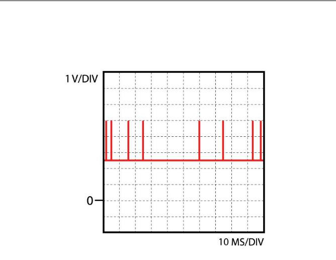
Accelerator pedal sensor
Function
The spindle which is connected to the accelerator pedal operates the position sensor. The sensor comprises a carbon strip and a stylus, the spindle operates the stylus. The stylus moves over the carbon strip, the voltage on the stylus depends on the position at which the stylus touches the carbon strip. Based on the output voltage the control unit determines fuel delivery.
Info
Quickcheck
Check connector(s): Inspect the connector(s) and if necessary clean or fix them to make sure the connection is good. Check supply voltage accelerator pedal position sensor: Turn off ignition. Remove connector from pedal position sensor. Turn ignition on. Measure voltage between supply terminal and the negative terminal of the battery. It should equal specified voltage. If not check wiring then check ECU. Check connection to ECU: Turn off ignition. Remove connector from pedal position sensor and ECU. Measure the resistance between connectors terminal and the corresponding terminal in the ECU connector. Should be < 1 ohm. If not check wiring. Check position sensor signal: Connect oscilloscope to the signal wire pin of the ECU and ground. Turn ignition on and compare to the data
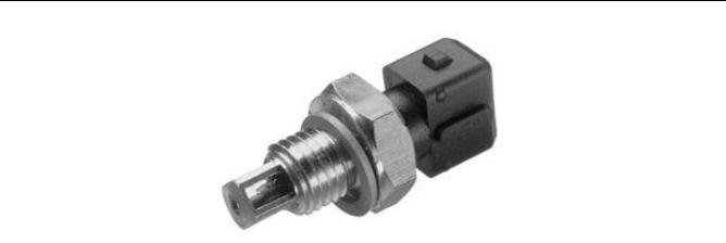
Air temperature sensor
Function
The air temperature sensor incorporates a NTC thermistor, the resistance decreases as the temperature of the air increases. As the temperature changes, the thermistor resistance changes, enabling the control unit to calculate the air temperature from the level of voltage that is registered on the sensors' signal wire.
Quickcheck
Check connector(s): Inspect the connector(s) and if necessary clean or fix them to make sure the connection is good. Check resistance: Turn off ignition. Remove connector from sensor. Measure resistance between pins of the sensor. Compare with specified resistance. Check supply voltage: Turn off ignition. Remove connector from sensor. Turn ignition on and measure successively voltage between connector terminal and the negative terminal of the battery. One should be 5 V. If not check wiring then check ECU. Check connection to ECU: Turn off ignition. Remove connectors from sensor and ECU. Measure the resistance between supply voltage connector terminal and the corresponding terminal in the ECU connector. It should be < 1 ohm. If not check wiring. Check ground: Check in schematic if ground connection is connected to a direct ground or to the ECU. When it is connected directly to ground: Turn off ignition. Remove connector from sensor and measure resistance between ground connector terminal and the negative terminal of the battery. It should be < 1 ohm. If not check wiring. When it is connected to the ECU: Turn off ignition. Remove connector from sensor and ECU. Measure resistance between ground connector terminal and the corresponding terminal in the ECU connector. It should be < 1 ohm. If not check wiring then check ECU.
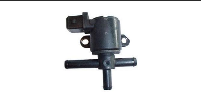
Boost pressure valve
Function
The solenoid controls a valve which opens or closes the air line between the waste gate valve and vacuum. When the valve opens vacuum is applied to the waste gate valve, which in turn regulates the amount of exhaust gasses passing through the exhaust gas turbine. In this way the turbo pressure is regulated.
Quickcheck
Check connector(s): Inspect the connector(s) and if necessary clean or fix them to make sure the connection is good. Check resistance: Turn off ignition. Remove connector from solenoid. Locate the two pins of the solenoid. Measure resistance between the two pins of the solenoid. Compare with specified resistance. Alternatively you can check functioning of the solenoid by applying battery voltage to the two pins of the solenoid, the solenoid should "click". Check supply voltage: Turn off ignition. Remove connector from solenoid. Locate the two connector terminals of the solenoid. Start the engine and measure voltage between one connector terminal of the solenoid and the negative terminal of the battery. Check the second terminal of the solenoid, one of the two should equal the battery voltage. If not check wiring and if present fuse and relay. Check connection to ECU: Turn off ignition. Remove connectors from solenoid and ECU. Locate the two connector terminals of the solenoid. Measure the resistance between one of the two connector terminals of the solenoid and the corresponding terminal in the ECU connector. Check the other terminal of the solenoid, one of the two should be < 1 ohm. If not check wiring.
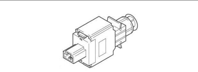
Brake pedal switch
Function
Engaging the brakes is detected by the brake pedal switch. There are single and double switches. Single switches send a voltage signal to the control unit, thus signaling that the brakes are engaged. In a double switch the additional switch actuates the brake lights.
Fault finding:
Check connector(s): Inspect the connector(s) and if necessary clean or fix them to make sure the connection is good. Check supply voltage:
Turn off ignition. Remove connector from brake pedal switch.
Turn ignition on. Measure voltage between connector terminal + and the negative terminal of the battery. Both should equal battery voltage. If not check wiring, relay and fuse(s).
Check connection to ECU:
Turn off ignition. Remove connector from brake pedal switch.
Measure the resistance between connector terminal + and - and the corresponding terminals in the ECU connector. Both should be < 1 ohm. If not check wiring.
Check switch signal:
Connect oscilloscope or voltage meter to the pin of the ECU which corresponds to the brake pedal switch and ground. Turn ignition on, output voltage should equal battery voltage. Press brake, output voltage should be 0 V. Connect oscilloscope or voltage meter to the pin of the ECU which corresponds to the brake light switch and ground. Turn ignition on, output voltage should be 0 V. Press brake, output voltage should equal battery voltage.

CAN BUS SAE J1708
Function
CAN bus connection SAE J1708 is a data chain used to send trouble code information etc. The voltage on the data chain varies and depends on the number of ECUs and the traffic on the line.
CAN BUS SAE J1939
Function
CAN bus connection SAE J1939 is an electric control chain used to send data that the system uses for control functions. The voltage on the control chain varies and depends on the number of ECUs and the traffic on the line.
Info

ECU lamp
Function
The control unit actuates the check engine light when it senses inadequate functioning of the motormanagement system.
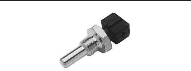
Coolant temperature sensor
Function
The coolant temperature sensor incorporates a NTC thermistor, the resistance decreases as the temperature of the coolant increases. As the temperature changes, the thermistor resistance changes, enabling the control unit to calculate the coolant temperature from the level of voltage that is registered on the sensors' signal wire.
Quickcheck
Inspect the connector(s) and if necessary clean or fix them to make sure the connection is good. Check resistance: Turn off ignition. Remove connector from sensor. Measure resistance between pins of the sensor. Compare with specified resistance. Check supply voltage: Turn off ignition. Remove connector from sensor. Turn ignition on and measure successively voltage between connector terminal and the negative terminal of the battery. One should be 5 V. If not check wiring then check ECU. Check connection to ECU: Turn off ignition. Remove connectors from sensor and ECU. Measure the resistance between supply voltage connector terminal and the corresponding terminal in the ECU connector. It should be < 1 ohm. If not check wiring. Check ground: Check in schematic if ground connection is connected to a direct ground or to the ECU. When it is connected directly to ground: Turn off ignition. Remove connector from sensor and measure resistance between ground connector terminal and the negative terminal of the battery. It should be < 1 ohm. If not check wiring. When it is connected to the ECU: Turn off ignition. Remove connector from sensor and ECU. Measure resistance between ground connector terminal and the corresponding terminal in the ECU connector. It should be < 1 ohm. If not check wiring then check ECU.
Diagnostic connector
Function
The diagnostic connector is connected to the control unit. It facilitates communication with the control unit to get information on stored error codes and/or operating states of sensors and actuators.
Fault finding:
"Check connector(s): Inspect the connector(s) and if necessary clean or fix them to make sure the connection is good. Check in schematic which diagnostic connector terminal is (are) connected to the connector terminal(s) of the ECU connector or ground. Measure the resistance between the ECU connector terminal(s) and each pin of the diagnostic connector. The resistance between the ECU connector terminal(s) and the corresponding terminal in the diagnostic connector should be < 1 ohm.
Measure the resistance between the negative terminal of the battery and each pin of the diagnostic connector. The resistance between the negative battery terminal and the corresponding terminal in the diagnostic connector should be < 1 ohm.
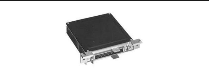
ECU
Function
The control unit is the electronic processing unit for the motormanagement system. The control unit has to ensure that the engine receives the right amount of fuel, the right injection timing and a proper idle control in every operating state. The control unit uses sensors to determine engine operating conditions. Depending on the engine conditions, the control unit activates actuators.
Quickcheck
Check connector(s): Inspect the connector(s) and if necessary clean or fix them to make sure the connection is good. When you suspect the control unit is faulty make sure all sensors, actuators and the communication with other control units function properly. Furthermore check the supply voltage and ground connections of the control unit: Turn ignition off. Remove ECU connector. Locate the supply voltage connections. Turn ignition on, measure voltage between corresponding connector terminal(s) and the negative terminal of the battery, these should equal battery voltage. If not check wiring and fuse. Turn ignition off. Locate the ground connections. Measure resistance between corresponding connector terminal(s) and the negative terminal of the battery, these should be < 1 ohm.
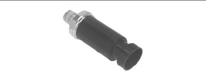
Exhaust pressure sensor
Function
The pressure in the exhaust is measured using the exhaust pressure sensor. The sensor is a transducer, the sensor senses the absolute pressure in the exhaust and transduces this to a DC voltage signal.
Quickcheck
Check connector(s): Inspect the connector(s) and if necessary clean or fix them to make sure the connection is good. Check supply voltage: Turn off ignition. Remove connector from sensor. Turn ignition on and measure voltage between the supplyterminal and negative terminal of the battery. It should be 5 V. Check connection to ECU: Turn off ignition. Remove connector from sensor and ECU. Measure the resistance between the terminals and the corresponding terminals in the ECU connector. They all should be < 1 ohm. If not check wiring.

Fuel temperature sensor
Function
The fuel temperature sensor incorporates a NTC thermistor, the resistance decreases as the temperature of the fuel increases. As the temperature changes, the thermistor resistance changes, enabling the control unit to calculate the fuel temperature from the level of voltage that is registered on the sensors' signal wire.
Quickcheck
Check connector(s): Inspect the connector(s) and if necessary clean or fix them to make sure the connection is good. Check resistance: Turn off ignition. Remove connector from diesel pump. Measure resistance between pin 1 and 2 of the connector. Compare with specified resistance. Check supply voltage: Turn off ignition. Remove connector from diesel pump. Turn ignition on and measure voltage between terminal 4 and the negative terminal of the battery. It should equal 5 V. If not check wiring then check ECU. Check connection to ECU: Turn off ignition. Remove connector from diesel pump and ECU. Measure the resistance between terminal 1, 2 and the corresponding terminals in the ECU connector, each one should be < 1 ohm. If not check wiring.
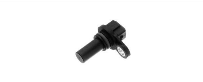
Inductive position sensor 1
Function
Function:
The sensor contains three parts: a coil, a magnet and a soft iron core. The teeth of a gearwheel move past the magnetic pickup which changes the magnetic field of the magnet, increasing when a tooth approaches and decreasing when a tooth moves away. These changes result in an AC voltage produced in the coil. Engine rpm and/or TDC are determined in this way.
Trouble shooting:
"Check connector(s): Inspect the connector(s) and if necessary clean or fix them to make sure the connection is good. Check resistance:
Turn off ignition. Remove connector from pickup sensor.
Measure resistance between the two pins of the coil of the pickup sensor. Compare with specified resistance. Check connection to ECU:
Turn off ignition. Remove connector from pickup sensor and ECU.
Measure the resistance between each coil connector terminal and the corresponding terminals in the ECU connector. Both should be < 1 ohm.
If present check shield connection:
Check in schematic if the shield terminal is connected to a direct ground or to the ECU. When it is connected to a direct ground: Turn off ignition. Remove connector from pickup sensor. Measure resistance between the shield connector terminal and the negative terminal of the battery. It should be < 1 ohm. When it is connected to the ECU: Turn off ignition. Remove connector from pickup sensor and ECU. Measure the resistance between the shield connector terminal and the corresponding terminal in the ECU connector. It should be < 1 ohm. If not check wiring.
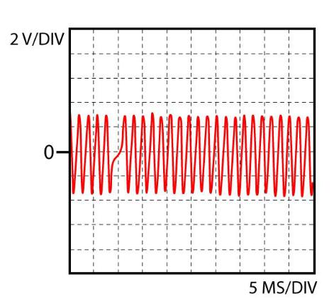
Check sensor signal:
Connect oscilloscope to signal wire pin of the ECU and ground. Start or crank the engine and compare to the scope image shown."
Info

Inductive position sensor 2
Function
Function:
The sensor contains three parts: a coil, a magnet and a soft iron core. The teeth of a gearwheel move past the magnetic pickup which changes the magnetic field of the magnet, increasing when a tooth approaches and decreasing when a tooth moves away. These changes result in an AC voltage produced in the coil. Engine rpm and/or TDC are determined in this way.
Trouble shooting:
"Check connector(s): Inspect the connector(s) and if necessary clean or fix them to make sure the connection is good. Check resistance:
Turn off ignition. Remove connector from pickup sensor.
Measure resistance between the two pins of the coil of the pickup sensor. Compare with specified resistance. Check connection to ECU:
Turn off ignition. Remove connector from pickup sensor and ECU.
Measure the resistance between each coil connector terminal and the corresponding terminals in the ECU connector. Both should be < 1 ohm.
If present check shield connection:
Check in schematic if the shield terminal is connected to a direct ground or to the ECU. When it is connected to a direct ground: Turn off ignition. Remove connector from pickup sensor. Measure resistance between the shield connector terminal and the negative terminal of the battery. It should be < 1 ohm. When it is connected to the ECU: Turn off ignition. Remove connector from pickup sensor and ECU. Measure the resistance between the shield connector terminal and the corresponding terminal in the ECU connector. It should be < 1 ohm. If not check wiring.
Check sensor signal:
Connect oscilloscope to signal wire pin of the ECU and ground. Start or crank the engine and compare to the scope image shown."
Info

 Loading...