

Page 1

CURSOR SERIES
C9
Technical and Repair manual
Page 2

This publication describes the characteristics, data and correct
methods for repair operations on each component of the vehicle.
If the instructions provided are followed and the specified
equipment is used, correct repair operations in the programmed time will be ensured, safeguarding against possible
accidents.
Before starting to perform whatever type of repair, ensurethat
all accident prevention equipment i s available and efficient.
All protections specified by safety regulations, i.e.: goggles,
helmet, gloves, boot, etc. must be checked and worn.
All machining, lifting and conveying equipment should be inspected before use.
The data contained in this publication was correct at the time
of going to press but due to possible modifications made by
the Manufacturer for reasons of a technical or commercial nature or for adaptation to the legal requirements of the different countries, some changes may have occurred.
No part of this publication, including the pictures, may be reproduced in any form or by any means.
Publication edited by
Iveco Motors
Iveco SpA
PowerTrain
Mkt. Advertising & Promotion
Viale dell’Industria, 15/17
20010 Pregnana Milanese
Milano (Italy)
Print P2D32C004E -1
st
Ed. 2006
Produced by:
B.U. TECHNICAL PUBLISHING
Iveco Technical Publications
Lungo Stura Lazio, 15
10156 Torino (TO) - Italy
Page 3

RYR
F2C CURSOR ENGINES
3
PRELIMINA
Manuals for repairs are split into Parts and Sections, each one of which is marked by a numeral; the contents of these sections are
indicated in the general table of contents.
The sections dealing with things mechanic introduce the specifications, tightening torque values, tool lists, assembly
detaching/reattaching operations, bench overhauling operations, diagnosis procedures and maintenance schedules.
The sections (or parts) of the electric/electronic system include the descriptions of the electric network and the assembly’s
electronic systems, wiring diagrams, electric features of components, component coding and the diagnosis procedures for the
control units peculiar to the electric system.
The manual uses proper symbols in its descriptions; the purpose of these symbols is to classify contained information. In particular,
there have been defined a set of symbols to classify warnings and a set for assistance operations.
EMARKS
SYMBOLS - WARNINGS
Danger for persons
Missing or incomplete observance of these prescriptions can cause serious danger for persons’ safety.
Danger of serious damage for the assembly
Failure to comply, both fully or in part, with such prescriptions will involve serious damage to the assembly and may
sometimes cause the warranty to become null and void.
!
NOTE
General danger
It includes the dangers of above described signals.
Environment protection
Moreover, it describes the correct actions to be taken to ensure that the assembly is used in such a way so as to protect
the environment as much as possible.
It indicates an additional explanation for a piece of information.
Print P2D32C004E Base - June 2006
Page 4

4
GENERAL WARNINGS
Warnings shown cannot berepresentative of all danger situations possiblyoccurring. Therefore, it is suggested to contact
immediate superiors where a danger situation occurs which is not described.
!
Use both specific and general-purpose toolings according to the prescriptions contained in respective use and
maintenance handbooks. Check use state and suitability of tools not subjected to regular check.
The manual handling of loads must be assessed in advance because it also depends, besides weight, on its size and on
the path.
Handling by mechanical means must be with hoisters proper as for weight as well as for shape and volume. Hoisters,
ropes and hooks used must contain clear indications on maximum carrying capacity acceptable. The use of said means
is compulsorily permitted to authorised personnel only. Stay duly clear of the load, and, anyhow, never under it.
In disassembling operations, always observe provided prescriptions; prevent mechanical parts being taken out from
accidentally striking workshop personnel.
Workshop jobs performed in pairs must always be performed in maximum safety; avoid operations which could be
dangerous for the co-operator because of lack of visibility or of his/her not correct position.
Keep personnel not authorised to operations clear of working area.
You shall get familiar with the operating and safety instructions for the assembly prior to operating on the latter. Strictly
follow all the safety indications found on the assembly.
Do not leave the running assembly unattended when making repairs.
F2C CURSOR ENGINES
When carrying out work on the assembly lifted off the ground, verify that the assembly is firmly placed on its supporting
stands, and that the manual/automatic safety devices have been actuated in the event that the assembly is to be lifted
by means of a hoist.
When you have to operate on assemblies powered by natural gas, follow the instructions contained in the document,
as well as all the specific safety standards provided for.
Only remove radiator cap when the engine is cold by cautiously unscrewing it in order to let system residual pressure
out.
Inflammable fuel and allinflammable fluids and liquids must be handledwith care, according to whatcontained onharmful
materials 12-point cards. Refuelling must be performed outdoors with the engine off, avoiding lit cigarettes, free flames
or sparksin order to prevent sudden fires/bursts.Adequately store inflammable, corrosive and polluting fluids and liquids
according to what provided by regulations in force. Compulsorily avoid to use food containers to store harmful liquids.
Avoid to drill or bore pressurised containers, and throw cloths impregnated with inflammable substances into suitable
containers.
Worn out, damaged or consumable parts must be replaced by IVECO Motors original spares.
During workshop activity,always keepthe work placeclean; timely clearor clean floors from accidental liquidor oil spots.
Electric sockets and electric equipment necessary to perform repair interventions must meet safety rules.
Base - June 2006 Print P2D32C004E
Page 5

F2C CURSOR ENGINES
GENERALWARNINGS
Put on, where required by the intervention, garments and protections provided in accident prevention rules; contact
with moving parts can cause serious injuries. Use suitable, preferably tight-fitted garments, and avoid to use jewels,
scarves, etc.
Do not leave the engine in motion at workshop locations not provided with a pipe to scavenge exhaust gas outside.
Avoid to breathe fumes coming from heating or from paint welding because they can cause damages to health; operate
outdoors or in suitably ventilated areas. Put on proper inspirator if paint powder is present.
Avoid contact with hot water or steam coming from the engine, radiator and pipings because they could cause serious
burns. Avoid direct contact with liquids and fluids present in vehicle systems; where an accidental contact has occurred,
refer to 12-point cards for provisions to make.
Clean the assemblies and carefully verify that they are intact prior to overhauling. Tidy up detached or disassembled
parts with their securing elements (screws, nuts, etc.) into special containers.
Check for the integrity of the parts which prevent screws from being unscrewed: broken washers, dowels, clips, etc.
Self-locking nuts with an insert made of nylon must always be replaced.
Avoid contact of rubber parts with diesel oil, petrol or other not compatible substances.
5
Before washing under pressure mechanical parts, protect electric connectors, and central units, if present.
Tightening screws and nuts must always be according to prescriptions; IVECO Motors commercial and assistance
network is available to give all clarifications necessary to perform repair interventions not provided in this document.
Before welding:
- Disconnect all electronic central units, take power cable off battery positive terminal (connect it to chassis bonding)
and detach connectors.
- Remove paint by using proper solvents or paint removers and clean relevant surfices with soap and water.
- Await about 15 minutes before welding.
- Equip with suitable fire resistant protections to protect hoses or other components where fluids or other materials
flow which may catch fire easily on welding.
Should the vehicle be subjected to temperatures exceeding 80qC (dryer ovens), disassemble drive electronic central
units.
The disposal of all liquids and fluids must be performed with full observance of specific rules in force.
Print P2D32C004E Base - June 2006
Page 6

6
GENERALWARNINGS ON THE ELECTRIC SYSTEM
If an intervention has to be made on the electric/electronic system, disconnect batteries from the system; in this case,
always disconnect, as a first one, the chassis bonding cable from batteries negative terminal.
!
Before connecting the batteries to the system, make sure that the system is well isolated.
Disconnect the external recharging apparatus from the public utility network before taking apparatus pins off battery
terminals.
Do not cause sparks to be generated in checking if the circuit is energised.
Do not use a test lamp in checking circuit continuity, but only use proper control apparatuses.
Make sure that the electronic devices wiring harnesses (length, lead type, location, strapping, connection to screening
braiding, bonding, etc.) comply with IVECO Motors system and are carefully recovered after repair or maintenance
interventions.
Measurements in drive electronic central units, plugged connections and electric connections to components can only
be made on proper testing lines with special plugs and plug bushes. Never use improper means like wires, screwdrivers,
clips and the like in order to avoid the danger of causing a short circuit, as well as of damaging plugged connections, which
would later cause contact problems.
F2C CURSOR ENGINES
NOTE
To start up the engine, donot use fast chargers. Start up must only be performed with either separate batteriesor special
truck.
A wrong polarisation of supply voltage in drive electronic central units (for instance, a wrong polarisation of batteries)
can cause them to be destroyed.
Disconnect the batteries from the system during their recharging with an external apparatus.
On connecting, only screw up connector (temperature sensors, pressure sensors etc.) nuts at prescribed tightening
torque.
Before disconnecting the junction connector from an electronic central unit, isolate the system.
Do not directly supply electronic central units servo com ponents at nominal vehicle voltage.
Cables must be arranged such as to result to be parallel to reference plane, i.e. as close as possible to chassis/body
structure.
Once the intervention on the electric system has been completed, recover connectors and wiring harnesses according
to original arrangement.
Connectors present mustbe seen from cable side.Connectors views contained in the manual are representative of cable
side.
Base - June 2006 Print P2D32C004E
Page 7
F2C CURSOR ENGINES
Bonding and screening
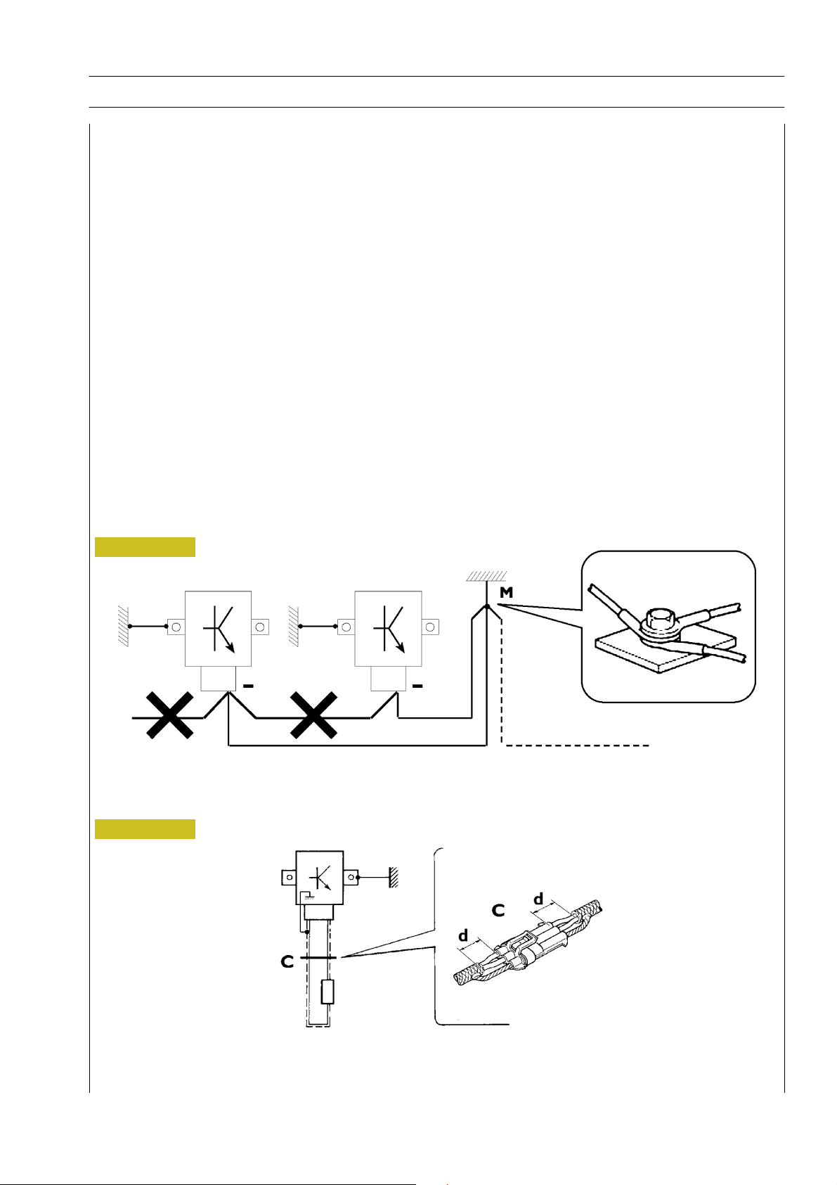
Negative leads connected to a system bonded point must be both as short and possible and “star“-connected to each other, trying
then to have their centering tidily and properly made (Figure 1, re. M).
Further, following warnings are to be compulsorily observed for electronic components:
- Electronic central units must be connected to system bonding when they are provided with a metallic shell.
- Electronic central units negative cables must be connected both to a system bonding point such as the dashboard opening
bonding (avoiding “serial“ or “chain“ connections), and to battery negative terminal.
- Analog bonding (sensors), although not connected to battery negative system/terminal bonding, must have optimal isolation.
Consequently, particularly considered must be parasitic resistances in lugs: oxidising, clinching defects, etc.
- Screened circuits braiding must only electrically contact the end towards the central unit entered by the signal (Figure 2).
- If junction connectors are present, unscreened section d, near them, must be as short as possible (Figure 2).
- Cables must be arranged such as to result to be parallel to reference plane, i.e. as close as possible to chassis/body structure.
7
Figure 1
1. NEGATIVE CABLES “STAR“ CONNECTION TO SYSTEM BONDING M
Figure 2
88039
2. SCREENING THROUGH METALLIC BRAIDING OF A CABLE TO AN ELECTRONIC COMPONENT — C. CONNECTOR
d. DISTANCE ! 0
Print P2D32C004E Base - June 2006
Page 8

8
F2C CURSOR ENGINES
OPTIONAL ELECTRICAL AND MECHANICAL PARTS INSTALLATIONS
Assemblies shall be modified and equipped with additions - and their accessories shall be fitted - in accordance with the assembling
directives issued by IVECO Motors.
It is reminded that, especially about the electric system, several electric sockets are provided for as series (or optional) sockets in
order to simplify and normalise the electrical intervention that is care of preparation personnel.
It is absolutely forbidden to make modifications or connections to electric central units wiring harnesses; in particular,
the data interconnection line between central units (CAN line) is to be considered inviolable.
CONVERSIONS BETWEEN THE MAIN UNITS OF MEASUREMENT OF THE
INTERNATIONAL SYSTEM AND MOST USED DERIVED QUANTITIES
Power
1 kW = 1.36 metric HP
1 kW = 1.34 HP
1 metric HP = 0.736 kW
1 metric HP = 0.986 HP
1 HP = 0.746 kW
1 HP = 1.014 metric HP
Torque
1 Nm = 0.1019 kgm
1 kgm = 9.81 Nm
Revolutions per time unit
1 rad/s = 1 rpm x 0.1046
1 rpm = 1 rad/s x 9.5602
Pressure
1 bar = 1.02 kg/cm
1 kg/cm
1bar = 10
2
= 0.981 bar
5
2
Pa
Where accuracy is not particularly needed:
- Nm unit is for the sake of simplicity converted into kgm according to ratio 10:1
1 kgm = 10 Nm;
2
- bar unit is for the sake of simplicity converted into kg/cm
1 kg/cm
2
=1bar.
according to ratio 1:1
Temperature
0q C=32q F
1q C = (1 x 1.8 + 32) q F
Base - June 2006 Print P2D32C004E
Page 9

F2C CURSOR ENGINES
1
F2C CURSOR ENGINES
Section
General specifications
Fuel 2
Industrial application 3
Overhaul and technical specifications 4
Tools 5
Safety prescriptions Appendix
1
PREFACE TO USER’S GUIDELINE MANUAL
Section 1 describes the F2C engine illustrating its features
and working in general.
Section 2 describes the type of fuel feed.
Section 3 relates to thespecific duty and is divided in four separate parts:
1. Mechanical part, related to the engine overhaul,
limited to those components with different characteristics
based on the relating specific duty.
2. Electrical part, concerning wiring harness, electrical
and electronic equipment with different characteristics
based on the relating specific duty.
3. Maintenance planning and specific overhaul.
4. Troubleshooting part dedicated to the operators who,
being entitled to provide technical assistance, shall have simple
and directinstructions to identify the causeof the major inconveniences.
Sections 4 and 5 illustrate the overhaul operationsof the engine overhaul on stand andthe necessary equipmentto execute
such operations.
The appendix contains a list of the general safety regulations
to be respected by all installation and maintenance engineers
in order to prevent serious accidents taking place.
Print P2D32C004E Base - June 2006
Page 10

2
F2C CURSOR ENGINES
Base - June 2006 Print P2D32C004E
Page 11
F2C CURSOR ENGINES
3
SPECIAL REMARKS
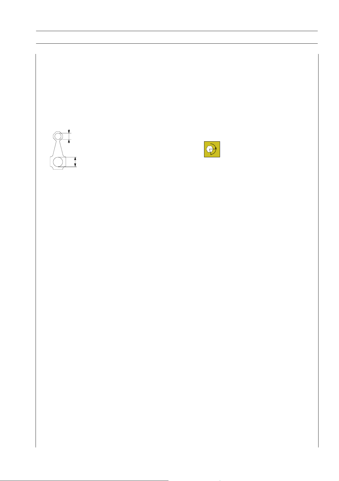
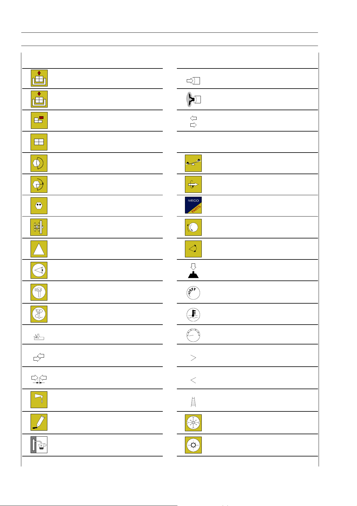
Diagrams and symbols have been widely used to give a clearer and more immediate illustration of the subject being dealt with, (see
next page) instead of giving descriptions of some operations or procedures.
Example
Ø 1 = h ousing for connecting rod small end bush
1
Tighten to torque
Tighten to torque + angular value
§
Ø 2 = h ousing for connecting rod bearings
2
Print P2D32C004E Base - June 2006
Page 12
4
Graph and symbols
F2C CURSOR ENGINES
Removal
Disconnection
Refitting
Connection
Removal
Disassembly
Fitting in place
Assembly
Tighten to torque
Tighten to torque + angle value Rolling torque
§
Press or caulk
Regulation
Adjustment
!
Warning
Note
¸
Intake
Exhaust
Operation
Compression ratio
Tolerance
Weight difference
Replacement
Original spare parts
Rotation
Angle
Angular value
Visual inspection
Fitting position check
Measurement
Value to find
Check
Equipment Temperature
Surface for machining
Machine finish
Interference
Strained assembly
Thickness
Clearance
Lubrication
Damp
Grease
Sealant
Adhesive
Air bleeding
bar
Preload
Number of revolutions
Pressure
Oversized
Higher than}.
Maximum, peak
Undersized
Less than}.
Minimum
Selection
Classes
Oversizing
Temperature < 0 qC
Cold
Winter
Temperature > 0 qC
Hot
Summer
Base - June 2006 Print P2D32C004E
Page 13

F2C CURSOR ENGINES
UPDATING
Section Description Page Date of revision
5
Print P2D32C004E Base - June 2006
Page 14

6
F2C CURSOR ENGINES
Base - June 2006 Print P2D32C004E
Page 15

F2C CURSOR ENGINES
SECTION 1 - GENERAL SPECIFICATIONS 1
SECTION 1
General Specifications
Page
TECHNICAL CODE 3......................
VIEWS OF THE ENGINE (for types: F2CE9684A*E004 -
F2CE9684B*E001 - F2CE9684C*E001 F2CE9684D*E001 - F2CE9684C*E002 -
F2CE9684E*E002) 5.....................
VIEWS OF THE ENGINE
(for types: F2CE9684L*E005) 8.............
LUBRICATION DIAGRAM 11.................
- Oil pump 12.............................
- Overpressure valve 12.....................
- Oil pressure control valve 13................
- Heat exchanger 13........................
ENGINE OIL FILTER 14......................
- Characteristics 14.........................
- Lock torques 14..........................
- Installation rule 14.........................
- Filter by-pass valve 14......................
- Oil fume recycle (Blow-by) 15...............
COOLING 16.............................
- Description 16...........................
- Operation 16............................
- Water pump 18..........................
- Thermostat 18...........................
TURBOCHARGING 19......................
EGR EXHAUST GAS RECYCLE SYSTEM 20......
INTERNAL EGR OPERATING ON
SUCTION VALVES 20.....................
Print P2D32C004E Base - June 2006
Page 16

2
SECTION 1 - GENERAL SPECIFICATIONS
F2C CURSOR ENGINES
Base - June 2006 Print P2D32C004E
Page 17

F2C CURSOR ENGINES
TECHNICAL CODE
SECTION 1 - GENERAL SPECIFICATIONS 3
Technical Code
F2CE9684A*E004
F2CE9684B*E001
F2CE9684C*E001
F2CE9684D*E001
F2CE9684C*E002
F2CE9684E*E002
F2CE9684H*E003
F2CE9684L*E005
Print P2D32C004E Base - June 2006
Page 18

4
SECTION 1 - GENERAL SPECIFICATIONS
F2C CURSOR ENGINES
Base - June 2006 Print P2D32C004E
Page 19
F2C CURSOR ENGINES
SECTION 1 - GENERAL SPECIFICATIONS
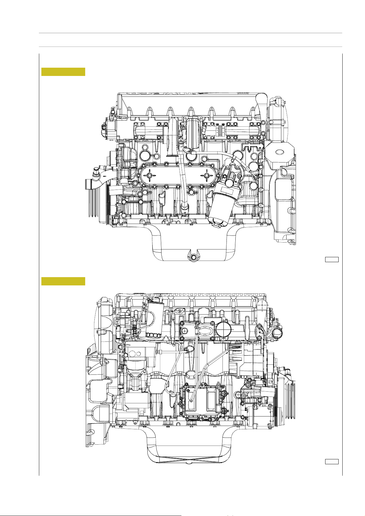
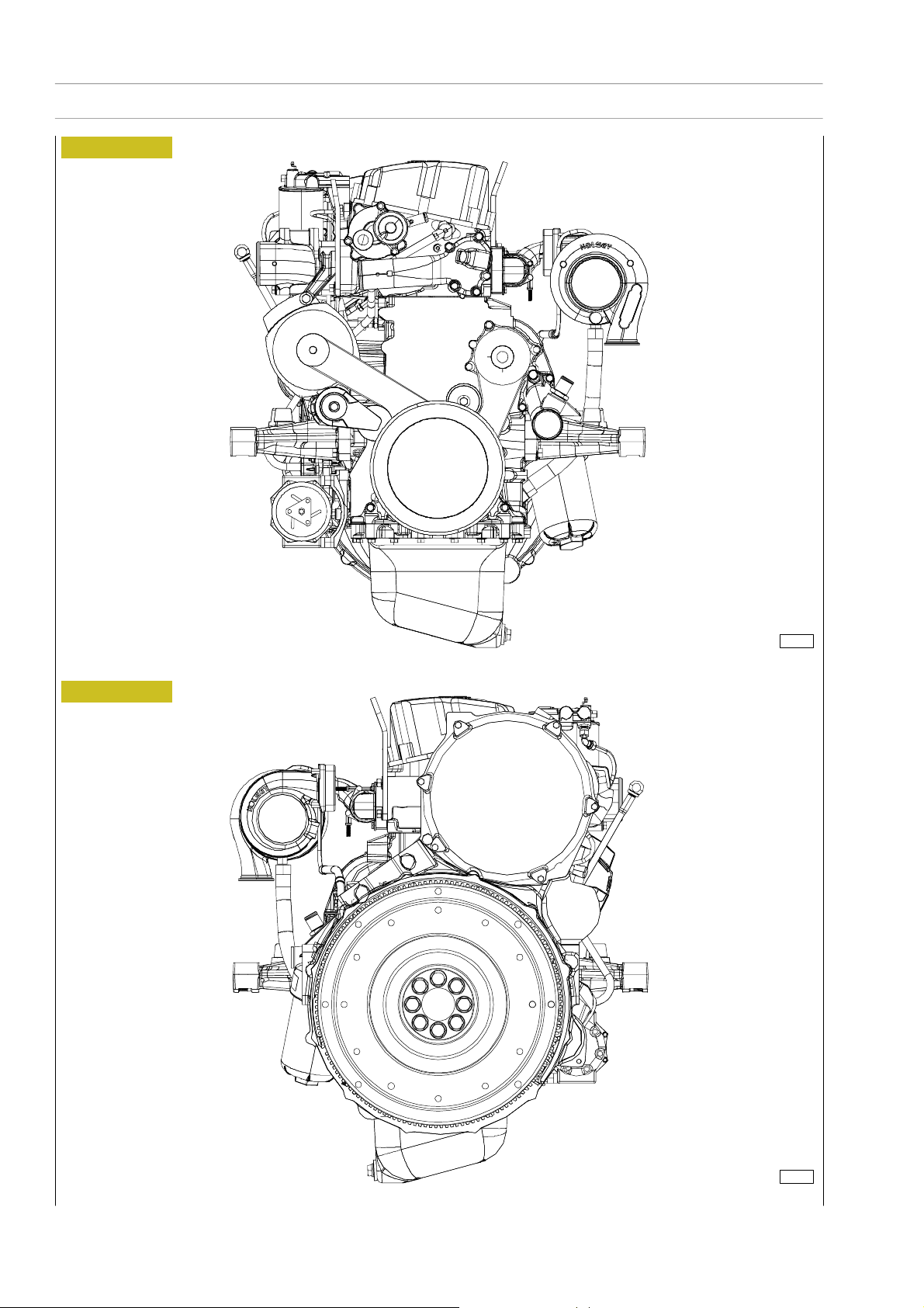
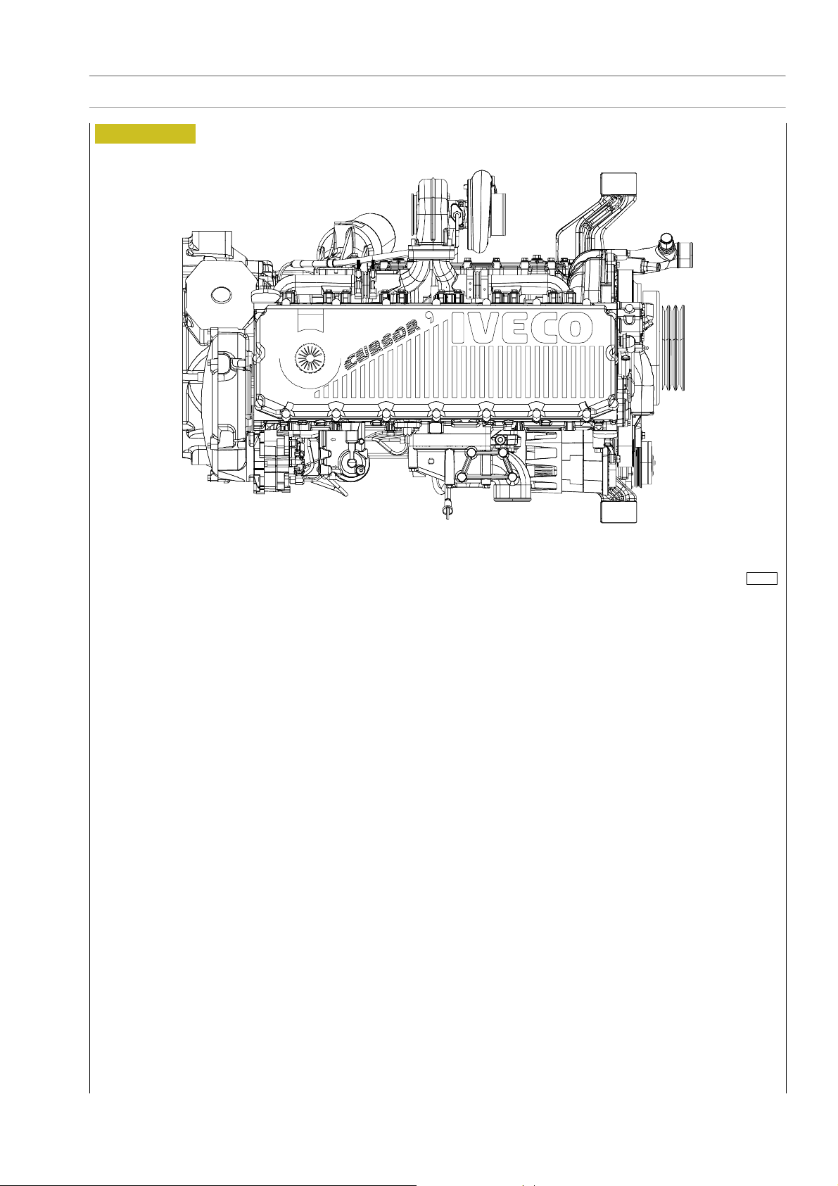
VIEWS OF THE ENGINE (for types: F2CE9684A*E004 - F2CE9684B*E001 - F2CE9684C*E001 F2CE9684D*E001 - F2CE9684C*E002 - F2CE9684E*E002)
Figure 1
5
Figure 2
113047
LEFT-HAND SIDE VIEW
113048
RIGHT-HAND SIDE VIEW
Print P2D32C004E Ba se - June 2006
Page 20
6
SECTION 1 - GENERAL SPECIFICATIONS
Figure 3
F2C CURSOR ENGINES
Figure 4
113049
FRONT HAND SIDE VIEW
113050
REAR HAND SIDE VIEW
Base - June 2006 Print P2D32C004E
Page 21
F2C CURSOR ENGINES
Figure 5
SECTION 1 - GENERAL SPECIFICATIONS
7
TOP VIEW
113051
Print P2D32C004E Ba se - June 2006
Page 22
8
SECTION 1 - GENERAL SPECIFICATIONS
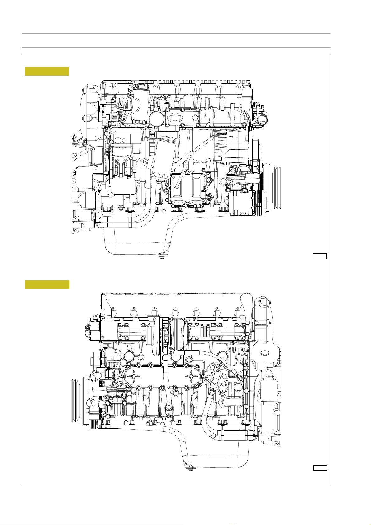
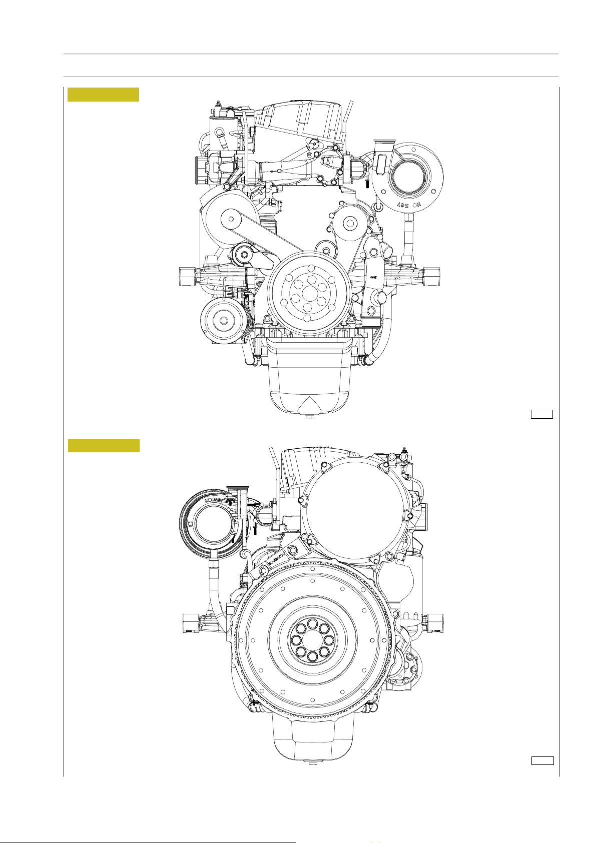
VIEWS OF THE ENGINE (for types: F2CE9684L*E005)
Figure 6
F2C CURSOR ENGINES
Figure 7
114203
RIGHT-HAND SIDE VIEW
114204
LEFT-HAND SIDE VIEW
Base - June 2006 Print P2D32C004E
Page 23
F2C CURSOR ENGINES
Figure 8
SECTION 1 - GENERAL SPECIFICATIONS
9
Figure 9
114205
FRONT-HAND SIDE VIEW
104206
REAR-HAND SIDE VIEW
Print P2D32C004E Ba se - June 2006
Page 24

10
SECTION 1 - GENERAL SPECIFICATIONS
Figure 10
F2C CURSOR ENGINES
TOP SIDE VIEW
114207
Base - June 2006 Print P2D32C004E
Page 25
F2C CURSOR ENGINES
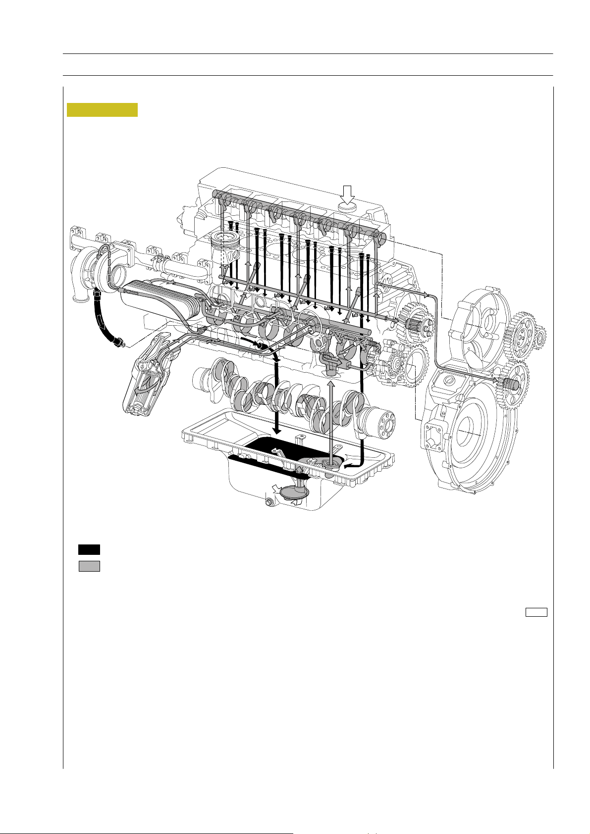
LUBRICATION DIAGRAM
Figure 11
SECTION 1 - GENERAL SPECIFICATIONS
11
Dropping oil
Pressure oil
114244
Print P2D32C004E Ba se - June 2006
Page 26
12
SECTION 1 - GENERAL SPECIFICATIONS
F2C CURSOR ENGINES
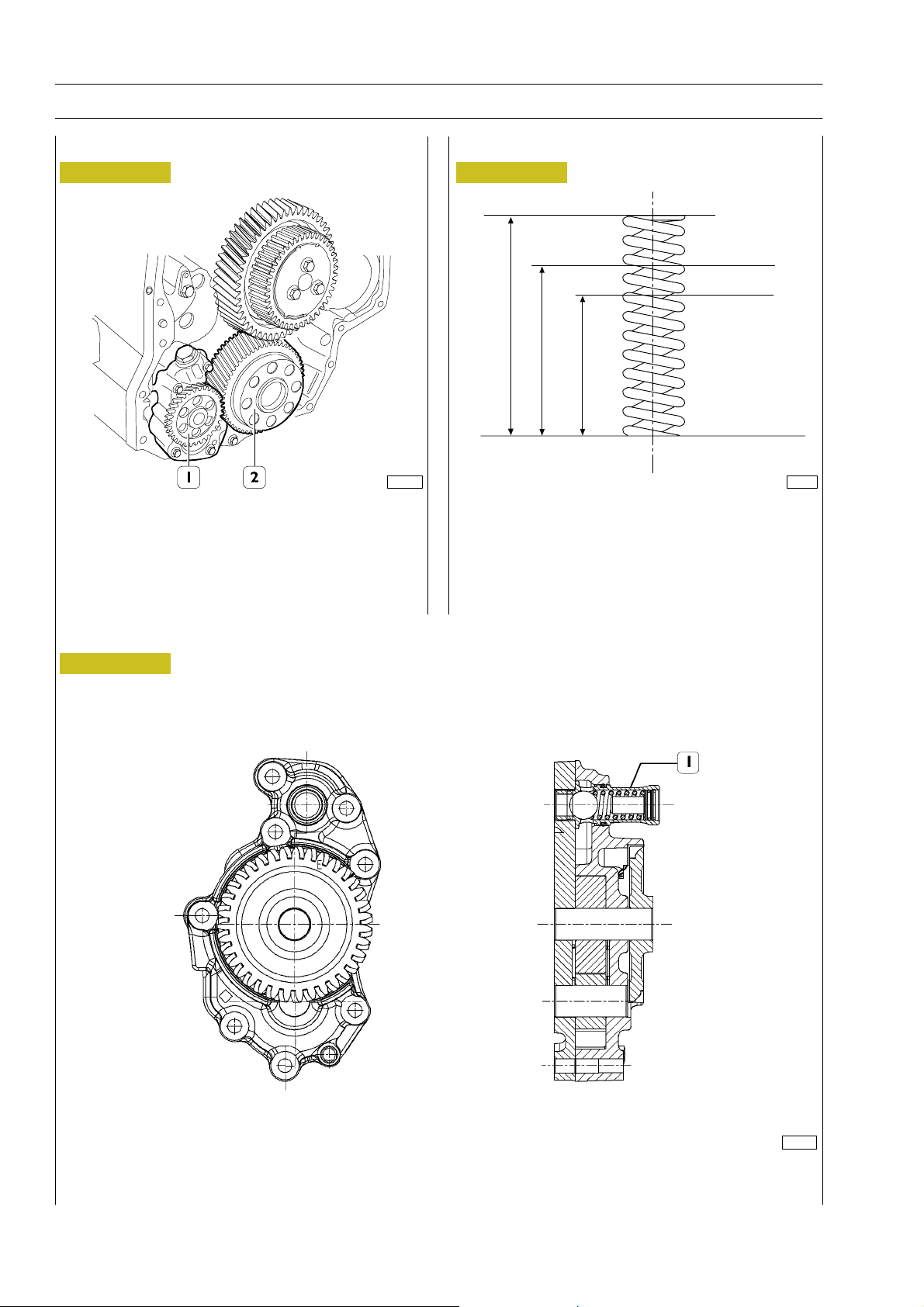
Oil pump
Figure 12
114245 77820
The oil pump (1) cannot be overhauled. On finding any
damage, replace the oil pump assembly.
See under the relevant heading for replacing the gear (2) of
the crankshaft.
Overpressure valve
Figure 14
190 r 6N
324 r 9N
43.65
33.5
22.95
MAIN DATA TO CHECK THE OVERPRESSURE
VALVE SPRING
Figure 13
112327
OIL PUMP CROSS-SECTION
1. Overpressure valve — Start of opening pressure 10.1 r0.7 bars.
Base - June 2006 Print P2D32C004E
Page 27
F2C CURSOR ENGINES
SECTION 1 - GENERAL SPECIFICATIONS
13
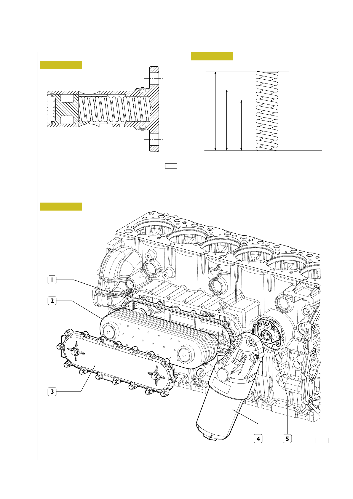
Oil pressure control valve
Figure 15
73542
The oil pressure control valve is located on the left-hand side
of the crankcase.
Start of opening pressure 5 bars.
Heat exchanger
Figure 17
Figure 16
168 r 9
308 r 15
63
51
36.4
88819
MAIN DATA TO CHECK THE OIL PRESSURE
CONTROL VALVE SPRING
114246
1. Exchanger seal - 2. Internal heat exchanger element - 3. Cover - 4.Oil filter - 5. Oil filter seal
Print P2D32C004E Ba se - June 2006
Page 28
14
SECTION 1 - GENERAL SPECIFICATIONS
ENGINE OIL FILTER
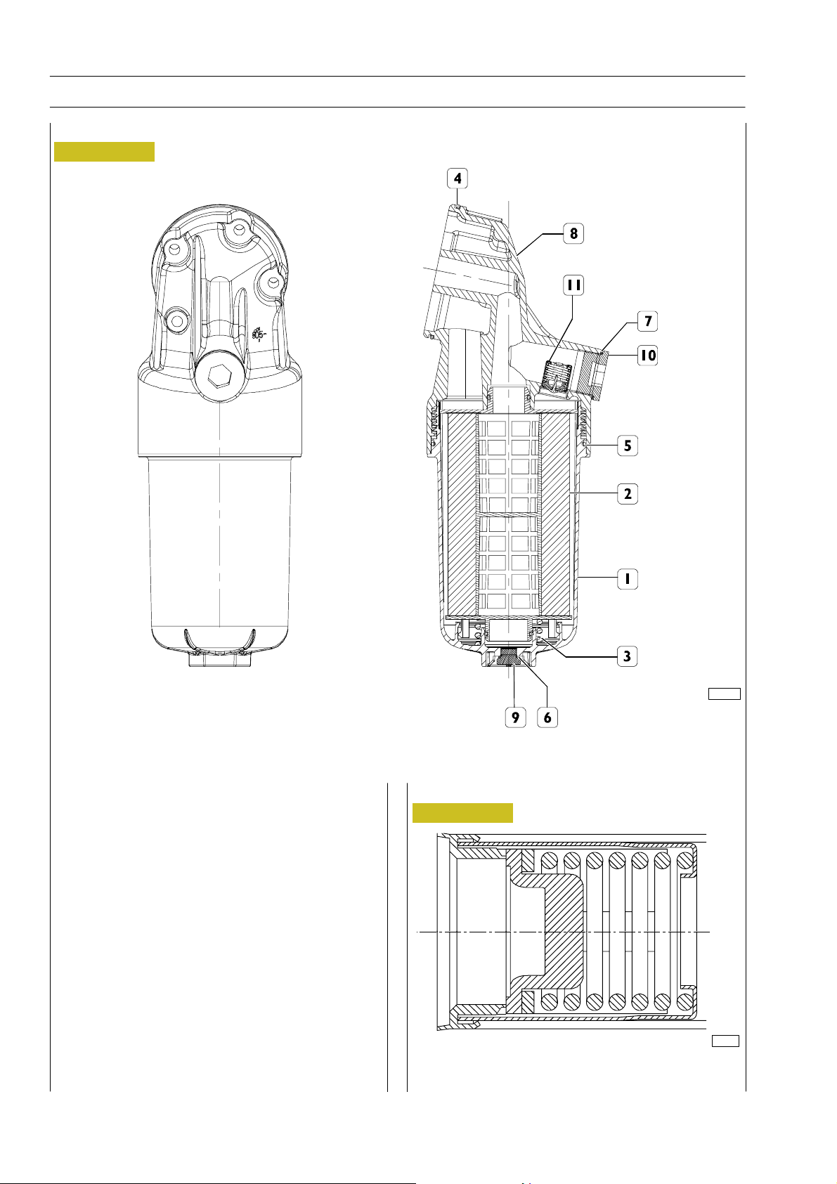
Figure 18
F2C CURSOR ENGINES
1. Closure cap - 2. Cartridge - 3. Spring - 4. Support O-ring - 5. Tank O-ring - 6. Washer - 7. Washer - 8. Support -
9. Plug M14x1.5 - 10. Plug M38x1.5 - 11. By-pass valve 3.4 bars.
Characteristics
1. Max working pressure: 13 bars
Filter by-pass valve
Figure 19
2. Working temperature: - 30q C y + 120q C
3. By-pass valve opening value: 3,4 r 0,3 bar
Lock torques
Cap (part 1): 60 r 5Nm
Plug (part 9): 30 r 5Nm
Plug (part 10): 90 r 5Nm
Installation rule
Use threadlock for plug (part 10).
Valve opens quickly at 3,4 r 0,3 bar pressure.
114247
73545
Base - June 2006 Print P2D32C004E
Page 29
F2C CURSOR ENGINES
SECTION 1 - GENERAL SPECIFICATIONS
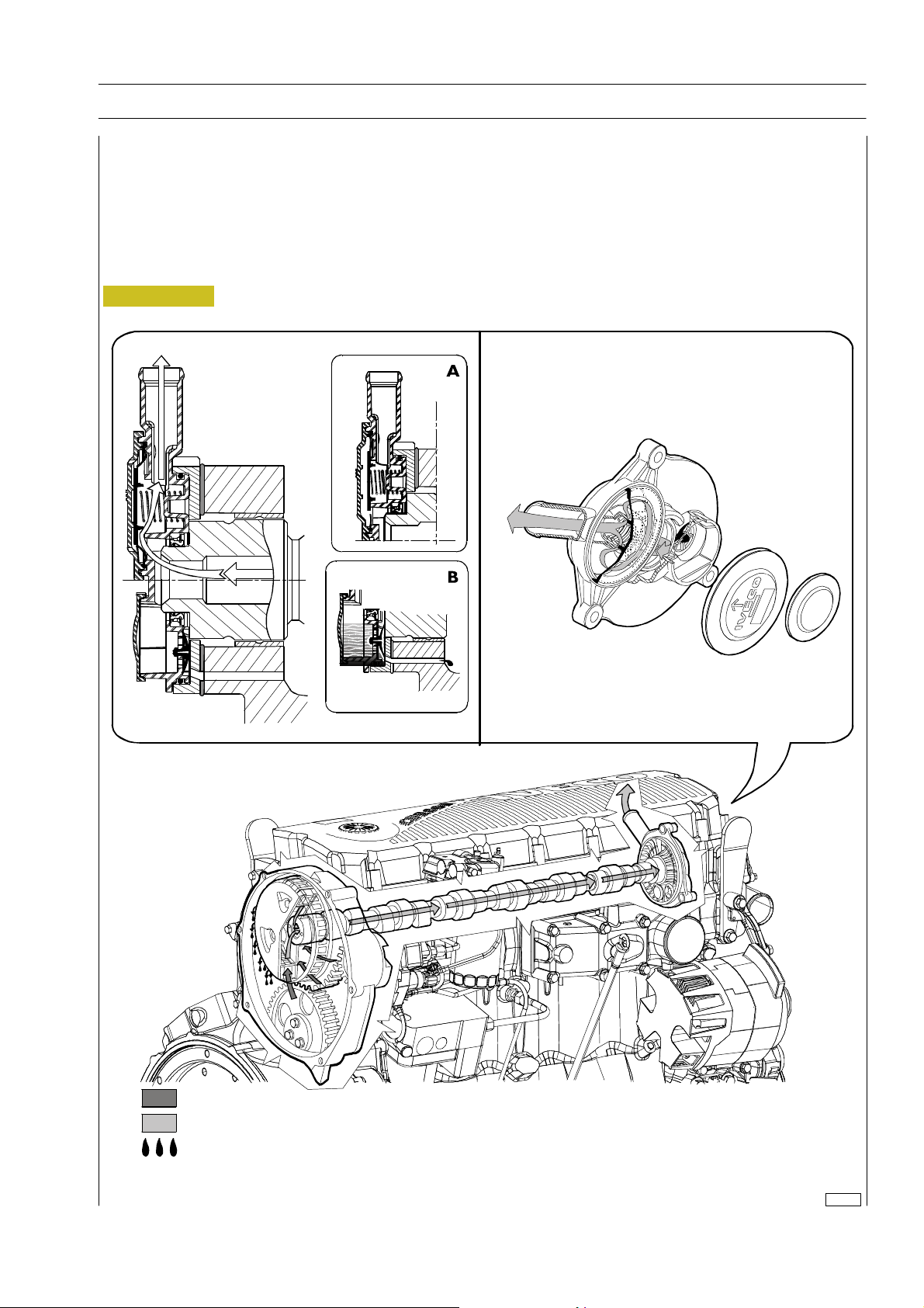
Oil fume recycle (Blow-by)
Part of gas produced by combustion during engine operation leaks through piston elastic ring openings into sump, mixing with
oil fumes in sump.
This mixture, conveyed upward, is partially separated from oil by a device located in timing cover upper part an d introduced in
air intake circuit.
The device mainly consists of a rotary filter secured on propeller shaft and by a front cover h ousing n ormally closed valves
controlling mixture flow.
Figure 20
15
Gas with oil contents greater than 10 g/h
Gas with oil contents approx. 0,2 g/h
Condensed oil returning to oil sump
114248
Print P2D32C004E Ba se - June 2006
Page 30

16
SECTION 1 - GENERAL SPECIFICATIONS
F2C CURSOR ENGINES
COOLING
Description
The engine cooling system is of the closed-circuit, forced circulation type.
It consists mainly of the following components:
- expansion tank, not supplied (by IVECO);
- a heat exchanger to c ool down lubrication oil;
- a water pump with centrifu gal system incorporated in the cylinder block;
- fan, not supplied;
- a 2-way th ermostat c ontrolling the coolant circulation.
Operation
The water pump is actuated by the crankshaft throu gh a poli-V belt and sends coolant to the cylinder block, especially to the
cylinder head (bigger quantity). When the coolant temperature reaches and overcomes the operating temperature, the
thermostat is opened and from here the coolant flows into the radiator and is cooled down by the fan.
The pressure inside the system, due to temperature change, is adequately controlled through the expansion vessel.
Base - June 2006 Print P2D32C004E
Page 31
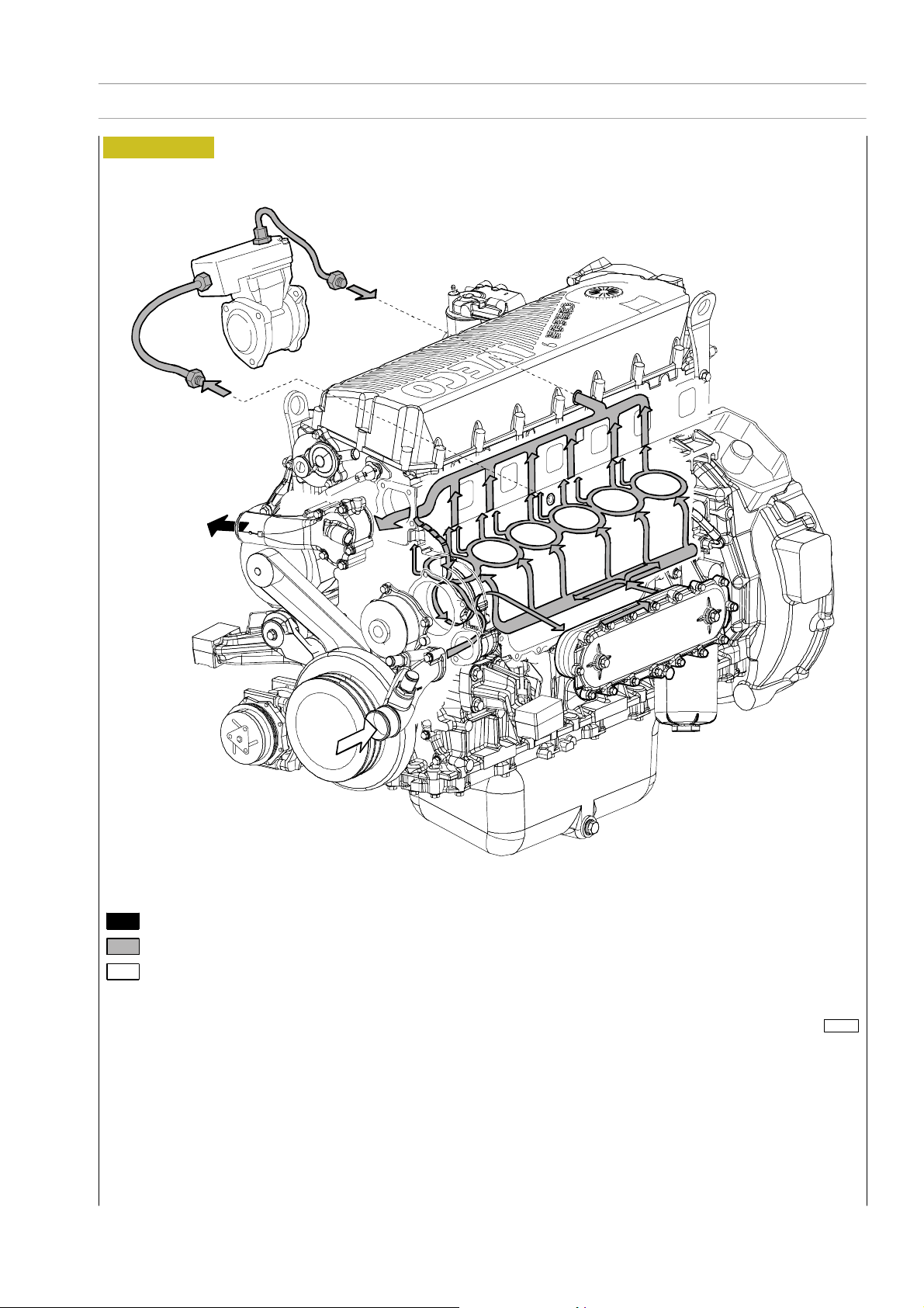
F2C CURSOR ENGINES
Figure 21
SECTION 1 - GENERAL SPECIFICATIONS
17
Water flowing out of the thermostat
Water circulating in the engine
Water flowing into the pump
114249
Print P2D32C004E Ba se - June 2006
Page 32
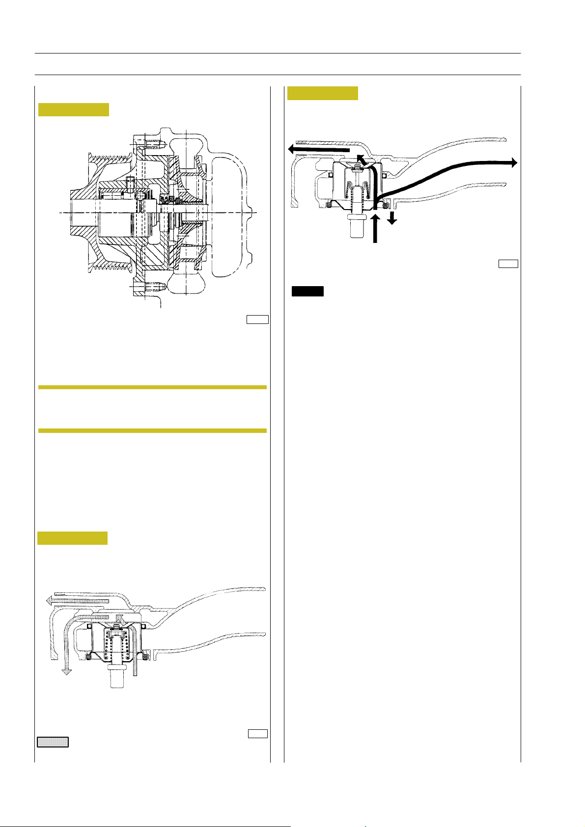
18
SECTION 1 - GENERAL SPECIFICATIONS
F2C CURSOR ENGINES
Water pump
Figure 22
114250
CROSS-SECTION OF THE WATER PUMP
The water pump consists of: rotor, shaft with bearing,
T-gasket and drive pulley with dust shield.
Figure 24
TO THE HEATER
TO RADIATOR
TO EXPANSION TANK
FROM THE HEAD
45358
Water leaving the thermostat
Check the thermostat works properly; replace it if in doubt.
Temperature of start of travel 84qC r2qC.
Minimumtravel15mmat94qC r2qC.
NOTE
Check that the pump body has no cracks or water
leakage; if it does, replace the entire water pump.
Thermostat
View of thermostat operation
Figure 23
TO THE HEATER
TO BY-PASS FROM THE HEAD
45357
Water circulating in the engine
Base - June 2006 Print P2D32C004E
Page 33
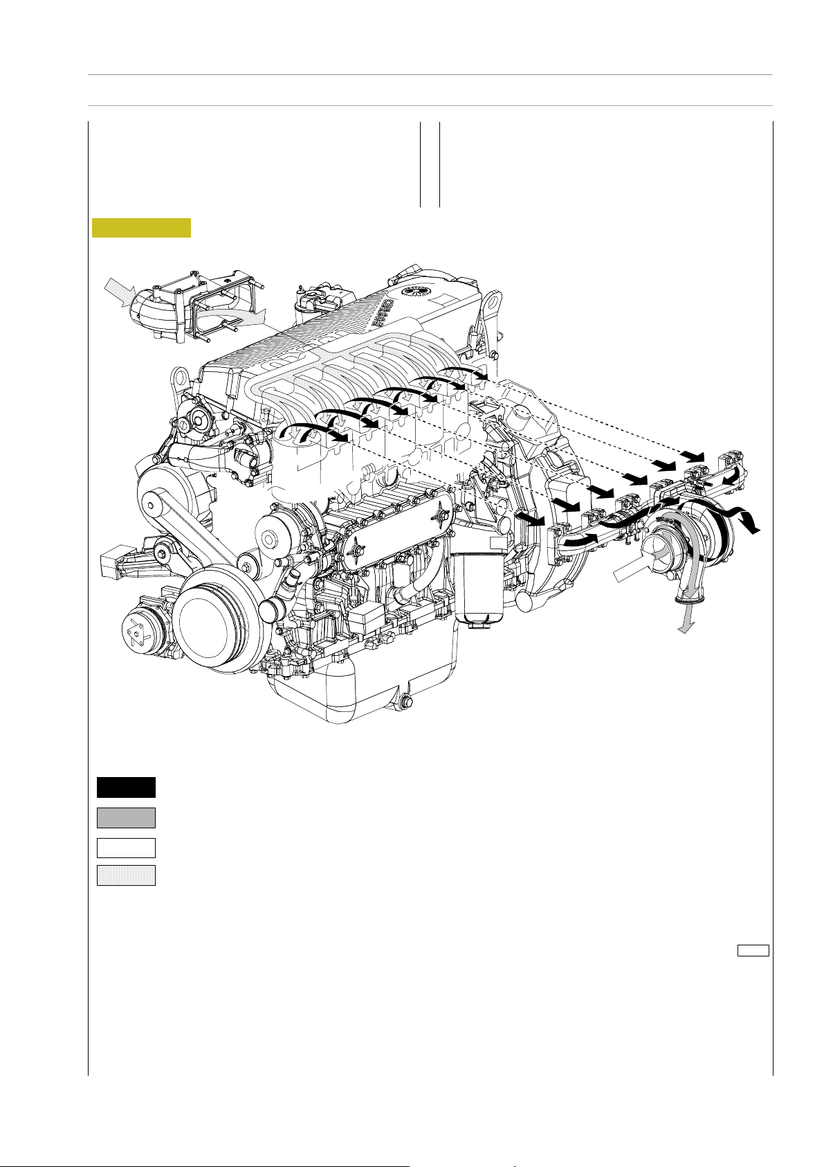
F2C CURSOR ENGINES
TURBOCHARGING
The turbocharging system consists of:
- air filter;
- Wastegate t urbocharger.
Figure 25
SECTION 1 - GENERAL SPECIFICATIONS
19
Exhaust gas
Compressed air (hot)
Inlet air
Intake compressed air
114251
Print P2D32C004E Ba se - June 2006
Page 34
20
SECTION 1 - GENERAL SPECIFICATIONS
F2C CURSOR ENGINES
EGR EXHAUST GAS RECYCLE SYSTEM
The exhaust gas can be partially recycled to cylinders to reduce maximum temperature values of combustionthat produce nitrogen oxides (NOx).
The exhaust gas recycle system (EGR) reduces combustion temperature and therefore is an efficient NOx emission control
system.
INTERNAL EGR OPERATING ON SUCTION VALVES
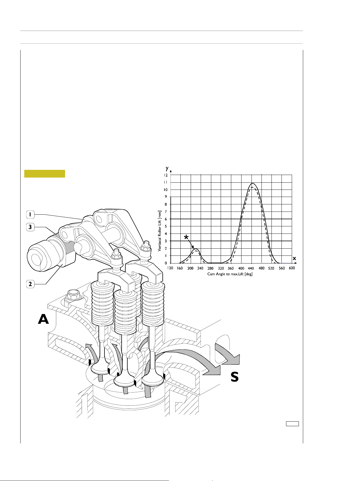
The specific design of suction cams of the internal EGR system allows part of exhaust gas to be recycled to engine cylinders.
This type of EGR, called internal EGR, is not equipped with any electronic control, th e system is always active. Its configuration
requires no additional parts such as control valves, pipelines or heat exchangers therefore engine profile remains unchanged.
Besides main lobe, suction cam has an additional lobe (3) as to configuration without EGR. During concerned cylinder exhaust
phase, this lobe allows a shaft advanced opening of intake valve (*). In this way, part of t he exhaust gas is trapped in the suction
duct and later, during cylinder suction phase, this gas is recycled to cylinder inlet for combustion phase.
Figure 26
Y : Valve lift in mm
X: Crankshaft adjustment
in degrees
– Valvetolerance=0mm
— — Valve tolerance = 0,4 mm
1. Exhaust cams - 2. Suction cams - 3. EGR lobe - S. Exhaust ducts - A. Intake ducts
114026
Base - June 2006 Print P2D32C004E
Page 35

F2C CURSOR ENGINES
SECTION 2 - FUEL 1
SECTION 2
Fuel
Page
SUPPLY 3................................
FUEL SUPPLY DIAGRAM 4..................
MECHANICAL SUPPLY PUMP 5..............
- Normal operating conditions 5..............
- Overpressure condition at outlet 5...........
- Drain c onditions 5.......................
CP3 HIGH-PRESSURE PUMP 6...............
HIGH-PRESSURE PUMP - INSIDE STRUCTURE 7
- Operating principle 8.....................
- Operation 10............................
RAIL (PRESSURE ACCUMULATOR) 10.........
- Electroinjector 10.........................
Print P2D32C004E Base - June 2006
Page 36

2
SECTION 2 - FUEL
F2C CURSOR ENGINES
Base - June 2006 Print P2D32C004E
Page 37
F2C CURSOR ENGINES
SECTION 2 - FUEL
SUPPLY
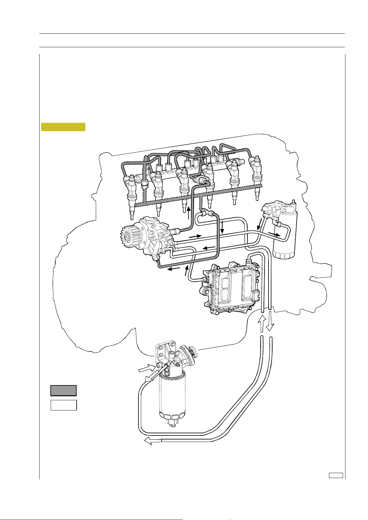
The Common Rail supply system is equipped with a special pump that maintains fuel at constant high pressure regardless
from phase and cylinder under inject ion and accumulated in an c ommon duct shared by all electric injectors.
Therefore, fuel at injection pressure, calc ulated by ECU, is always available at electric injection inlet.
When the solenoid valve of an injector is energized by ECU, in related cylinder the injection of fuel taken directly from the
rail takes place.
Figure 1
3
Return
circuit
Supply
circuit
114252
Print P2D32C004E Ba se - June 2006
Page 38
4
SECTION 2 - FUEL
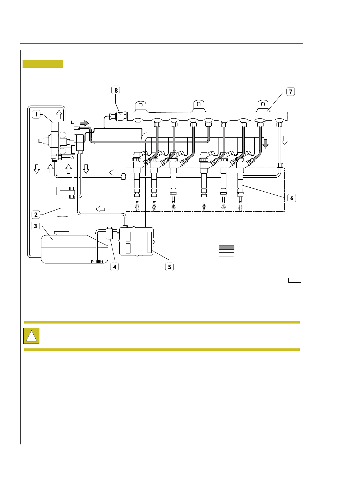
FUEL SUPPLY DIAGRAM
Figure 2
F2C CURSOR ENGINES
High pressure
Low pressure
1.High-pressurepump-2.Fuelfilter-3.Tank-4.Fuelpre-filter-5.ECU-6.Electricinjectors-7.CommonRail-
8. Pressure sensor
After high-pressure pipeline installation, during the following 20 hours of work, frequently check engine oil level.
!
(ITMUSTNOTINCREASE).
114253
Base - June 2006 Print P2D32C004E
Page 39
F2C CURSOR ENGINES
SECTION 2 - FUEL
5
MECHANICAL SUPPLY PUMP
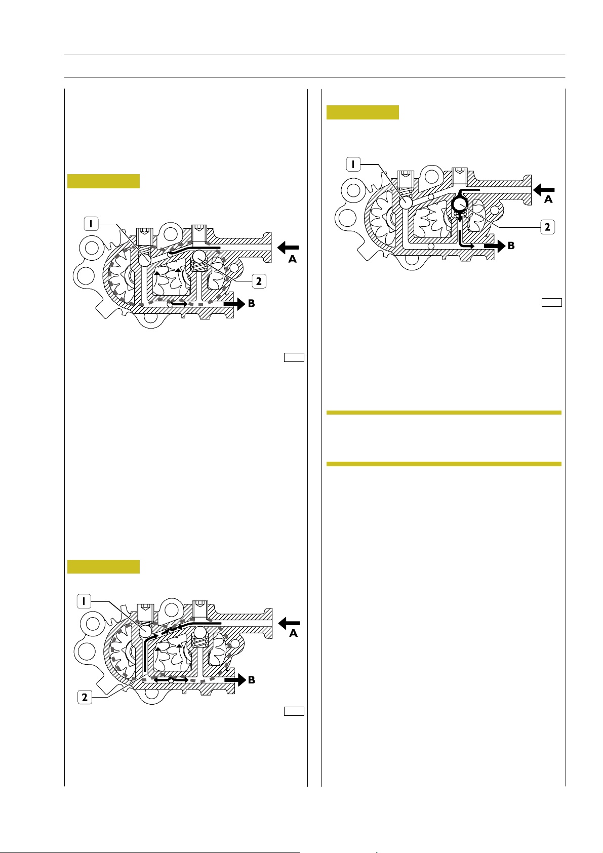
Gear pump, fitted on the rear side of the high pressure pump
andusedtosupplyit.
It is controlled by high pressure pump shaft.
Normal operating conditions
Figure 3
72592
A Fuel inlet from tank, B fuel outlet to filter, 1-2 by-pass valves
in close position
Drain conditions
Figure 5
72594
The by-pass valve (2) cuts in when, with engine off, the fuel
system shall be filled through the priming pump. In this
situation the by-pass valve (1) st ays closed whereas by-pass
valve (2) opens due to inlet pressure, and fuel is drained out
through B.
Overpressure condition at outlet
Figure 4
72593
NOTE
The mechanical supply pump cannot be replaced
individually, therefore it cannot be removed from
the high pressure pump.
The by-pass valve (1) cuts in when overpressure is generated
at outlet B. The existing pressure, overcoming valve spring(1)
elastic strength, makes inlet and outlet communicating
through duct (2).
Print P2D32C004E Ba se - June 2006
Page 40
6
SECTION 2 - FUEL
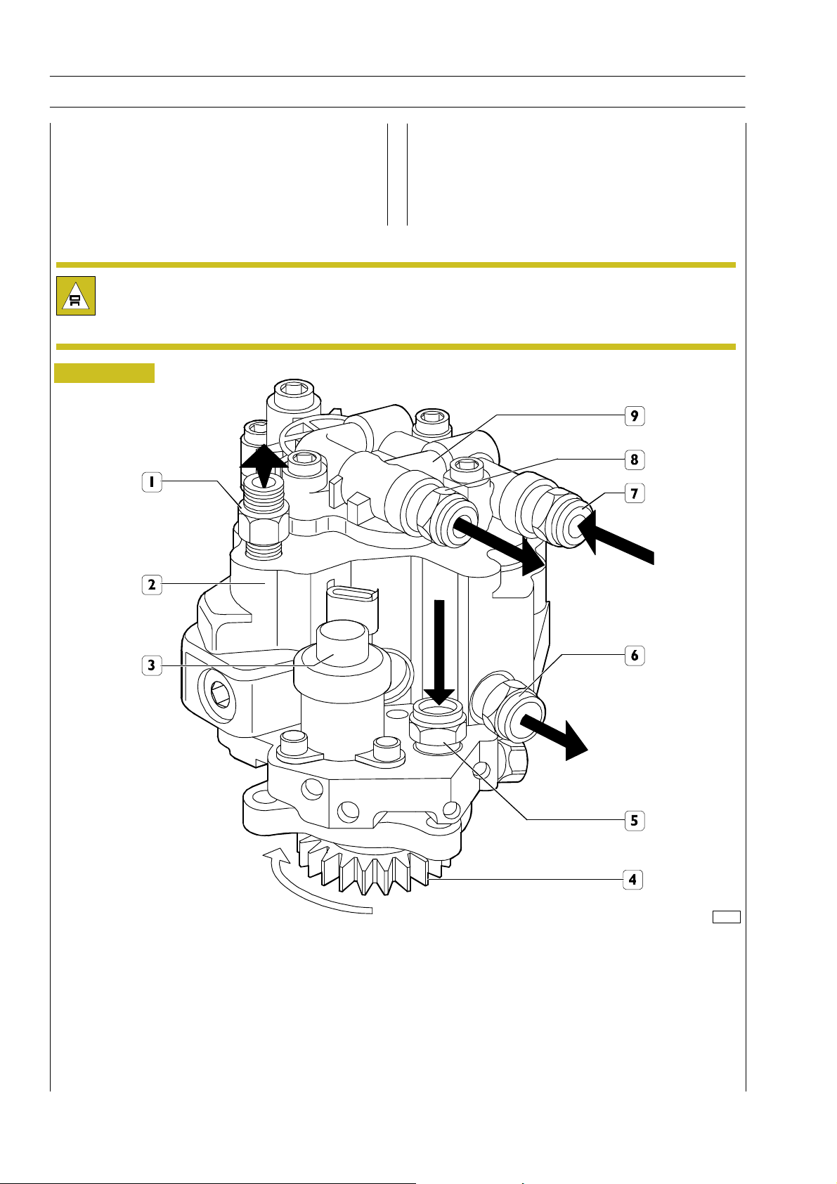
CP3 HIGH-PRESSURE PUMP
Pump with 3 radial pistons controlled by the timing gear,
without needing any setting. On the rear side of the high
pressure pump is fitted the mechanical supply pump
controlled by the high pressure pump shaft.
The following work must be carried out on the feed pump / high-pressure pump assembly:
- replacing the drive gear;
- replacing the pressure regulator.
Figure 6
F2C CURSOR ENGINES
72595
1. Fuel outlet fitting to rail - 2. High-pressure pump - 3. Pressure regulator - 4. Control gear - 5. Fuel inlet fitting from filter -
6. Fuel outlet fitting to filter support - 7. Fuel inlet fitting from control unit heat exchanger - 8. Fuel outlet fitting from supply
pump to filter - 9. Mechanical supply pump
Base - June 2006 Print P2D32C004E
Page 41
F2C CURSOR ENGINES
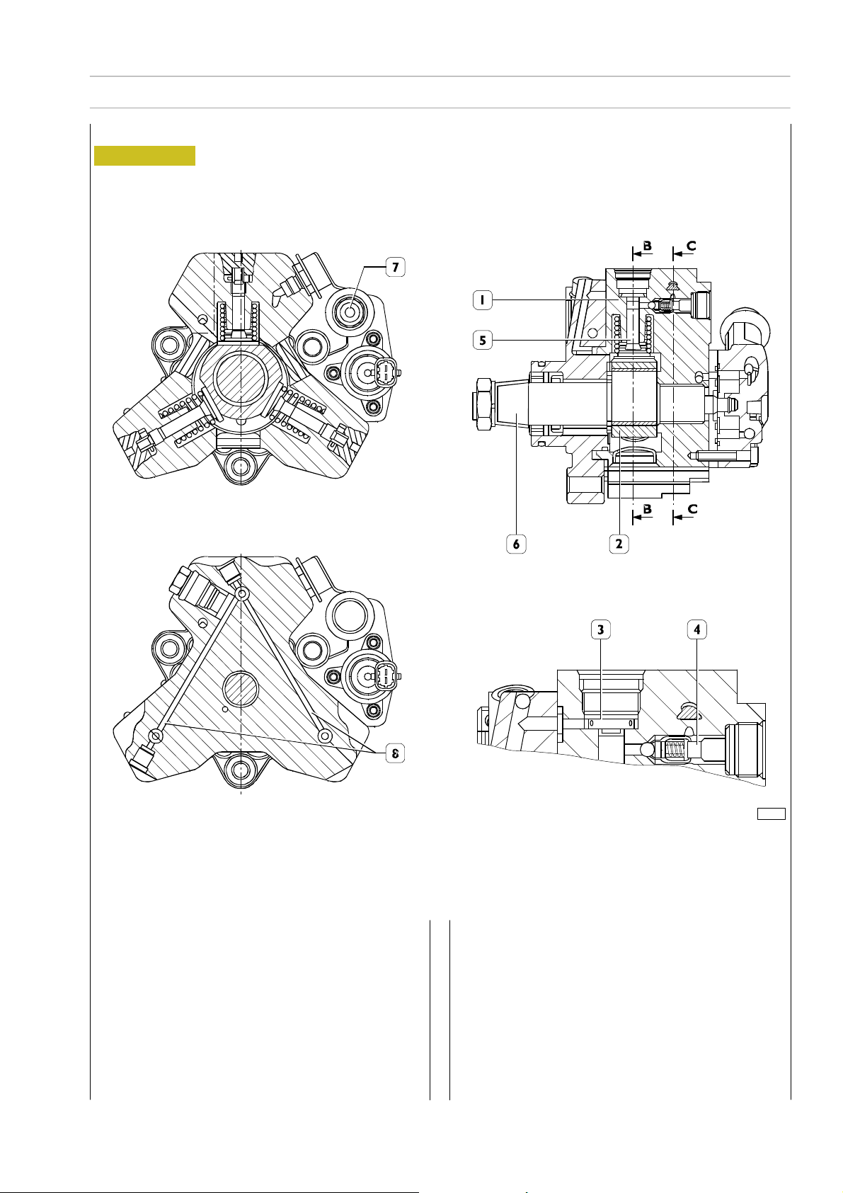
HIGH-PRESSURE PUMP - INSIDE STRUCTURE
Figure 7
sec. B-B
SECTION 2 - FUEL
7
sec. C-C
1. Cylinder — 2. Three-lobe element — 3. Cap intake valve — 4. Ball delivery valve — 5. Piston — 6. Pump shaft —
7. Low-pressure fuel inlet — 8. Pumping elements supplying fuel ducts
Every pumping unit is composed of:
- a piston (5) actuated by a three-lobeelement (2) floating
on the pump shaft (6). The element (2), being floating
on a misaligned part of the shaft (6), when the shaft
rotates, does not rotate therewith but is only
translated in a circular movement along a wider radius, with
the resulting alternate actuation of the three pumping
elements;
- cap in take valve (3);
- ball delivery valve (4).
70498
Print P2D32C004E Ba se - June 2006
Page 42
8
SECTION 2 - FUEL
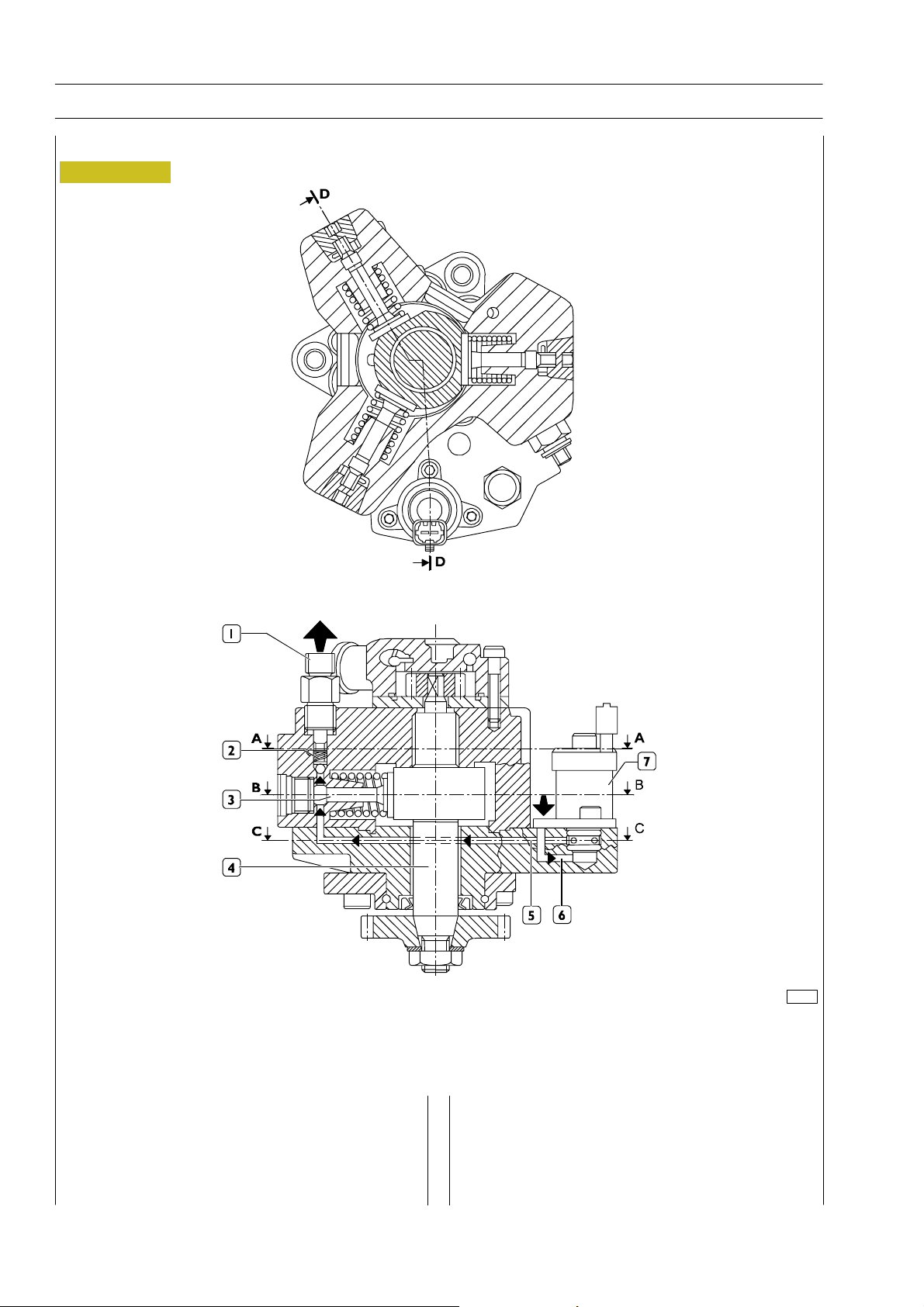
Operating principle
Figure 8
F2C CURSOR ENGINES
Sec. B — B
Sec. D — D
72597
1. Fuel outlet fitting to rail - 2. Delivery valve to rail - 3. Pumping element - 4. Pump shaft - 5. Pumping element supply duct -
6. Pressure regulator supply duct - 7. Pressure regulator
Pumping element (3) is oriented to pump shaft (4) cam.
During intake, the pumping element is su pplied through
supply duct (5). The fuel amount to be sent to the pumping
element is set by the pressure regulator (7). The pressure
the PWM signal received from ECU. During pumping
element compression stage, fuel reaches the pressure
required to open the delivery valve to common rail (2) and
to feed it through outlet (1).
regulator meters fuel flow t o pumping element according to
Base - June 2006 Print P2D32C004E
Page 43
F2C CURSOR ENGINES
SECTION 2 - FUEL
9
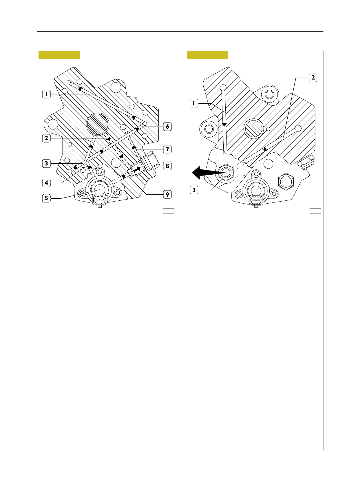
Figure 9
Sec.C—C
72598
Figure 10
Sec. A — A
72601
1. Pumping element inlet - 2. Pump lubrication ducts -
3. Pumping element inlet - 4. Main pumping element
supply duct - 5. Pressure regulator - 6. Pumping element
inlet - 7. Regulator exhaust duct - 8. 5 bar pressure relief
valve - 9. Fuel drain from regulator inlet
Figure 9 shows low pressure fuel paths inside the path and
highlights: main pumping element supply duct (4), pumping
element supply ducts (1 — 3 — 6), pump lubrication ducts (2),
pressure regulator (5), 5 bar pressure relief valve (8) and fuel
drain duct (7).
Pump shaft is lubricated by fuel through delivery and return
ducts (2).
Pressure regulator (5) establishes the fuel amount to send to
pumping elements; excess fuel is drained out through duct
(9).
5 bar pressure relief valve acts as fuel exhaust manifold and
keeps 5 bar constant pressure at regulator inlet.
1. Fuel outlet duct - 2. Fuel outlet duct - 3. Fuel outlet
from pump with high pressure pipe fitting for common rail
Figure 10 shows high pressure fuel flow through pumping
element outlet ducts.
Print P2D32C004E Ba se - June 2006
Page 44
10
SECTION 2 - FUEL
F2C CURSOR ENGINES
Operation
The cylinder is filled through the cap intake valve only if the
supply pressure is suitable to open the delivery valves set on
the pumping elements (about 2 bars).
The amount of fuel supplying the high-pressure pump is
metered by th e pressure regulator, placed on the
low-pressure system; the pressure regulator is controlled by
the EDC7 control unit through a PWM signal.
When fuel is sent to a pumping element, the related piston
is moving downwards (suction stroke). When the piston
stroke is reversed, the intake valve closes and the remaining
fuel in the pumping element chamber, not being able to come
out, is compressed above the supply pressure value existing
in the rail.
The thereby-generated pressure makes the exhaust valve
open and the compressed fuel reaches the high-pressure
circuit.
The pumping element compresses the fuel till the top dead
center (delivery stroke) is reached. Afterwards, the pressure
decreases till the exhaust valve is closed.
The pumping element piston goes back towards the bottom
dead center and the remaining fuel is decompressed.
When the pumping element chamber pressure becomes less
than the supply pressure, the intake valve is again opened and
the cycle is repeated.
The delivery valves must always be free in their movements,
free from impurities and oxidation.
The rail delivery pressure is modulated by the electronic
control unit, through the pressure regulator solenoid valve.
The pump is lubricated and cooled by the fuel.
The radialjet pump discon nection — reconnec tion time on
the engine is highly reduced in comparison with traditional
injection pumps, because it does not require setting.
If the pipe between fuel filter and high-pressure pump is to
be removed-refitted, be sure that handsand components are
absolutely clean.
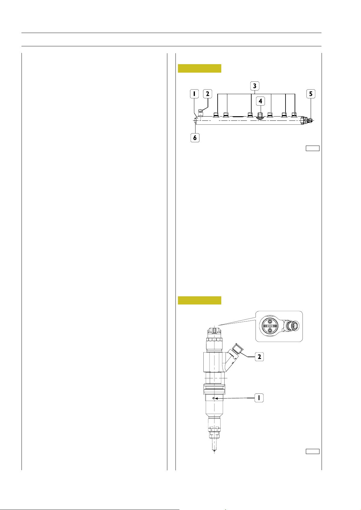
RAIL (PRESSURE ACCUMULATOR)
Figure 11
114254
1. Rail - 2. Fuel return - 3.Pipelines to injec tors - 4. Fuel
supply to high pressure pump - 5. Pressure sensor -
6. Overpressure valve
The rail volume is of reduced sizes to allow a quick
pressurisation at startup, at idle and in case of high flow-rates.
It anyway has enough volume as to minimise use of plenum
chambers caused by injectors openings and closings and by
the high-pressure pump operation. This function is further
enabled by a calibrated hole being set down stream of the
high-pressure pump.
A fuel pressure sensor (5) is screwed to the rail. The signal
sent by this sensor to the electronic control unit is a
feed-back information , depending on which the rail pressure
value is checked and, if necessary, corrected.
Electroinjector
Figure 12
114255
1. Fuel return hole - 2. Fuel supply
Base - June 2006 Print P2D32C004E
Page 45

F2C CURSOR ENGINES
SECTION 3 - INDUSTRIAL APPLICATION
SECTION 3
Industrial application
CLEARANCE DATA 3.....................
PART ONE -
MECHANICAL COMPONENTS 5.........
ENGINE DISASSEMBLY ON BENCH 7........
ASSEMBLY 11.............................
- High pressure pump installation 15...........
ENGINE FLYWHEEL 15.....................
- Engine flywheel installation 15...............
- Camshaft installation 16....................
- Camshaft tuning 17.......................
1
Page
- Tune wheel timing 20.....................
- Intake and exhaust rocker arm clearan ce
adjustment 21............................
ENGINE ASSEMBLY COMPLETION 22.........
PART TWO -
ELECTRICAL EQUIPMENT 25.............
- Components on the engine F2C 27...........
- EDC 7 UC31 electronic control unit 28.......
- EDC control unit PIN-OUT 29..............
- Electroinjectors 32........................
- Engine coolant temperature sensor 33........
- Fuel temperature sensor 34.................
- High pressure pump (pressure regulator) 35....
- Flywheel pulse transmitter 36................
- Distribution pulse transmitter 37.............
- Fuel pressure sensor on rail 40...............
Print P2D32C004E Ba se - June 2006
Page 46

2
SECTION 3 - INDUSTRIAL APPLICATION
- Alternator
(for types: F2CE9684A - F2CE9684B F2CE9684C*E001 - F2CE9684D - F2CE9684L) 41
- Alternator
(for types: F2CE9684C*E002 - F2CE9684E) 42.
- Alternator (per type: F2CE9684H) 43.........
- Starting motor 44........................
PRE/POST-HEATING RESISTANCE 45..........
EDC SYSTEM FUNCTIONS 46................
PART THREE - TROUBLESHOOTING 49.......
PREFACE 51...............................
PART FOUR -
MAINTENANCE PLANNING 55............
F2C CURSOR ENGINES
Page
MAINTENANCE 57.........................
- Maintenance services chart 57...............
CHECKS AND/OR MAINTENANCE WORK 58...
OFF-PLANE OPERATIONS 59.................
Base - June 2006 Print P2D32C004E
Page 47
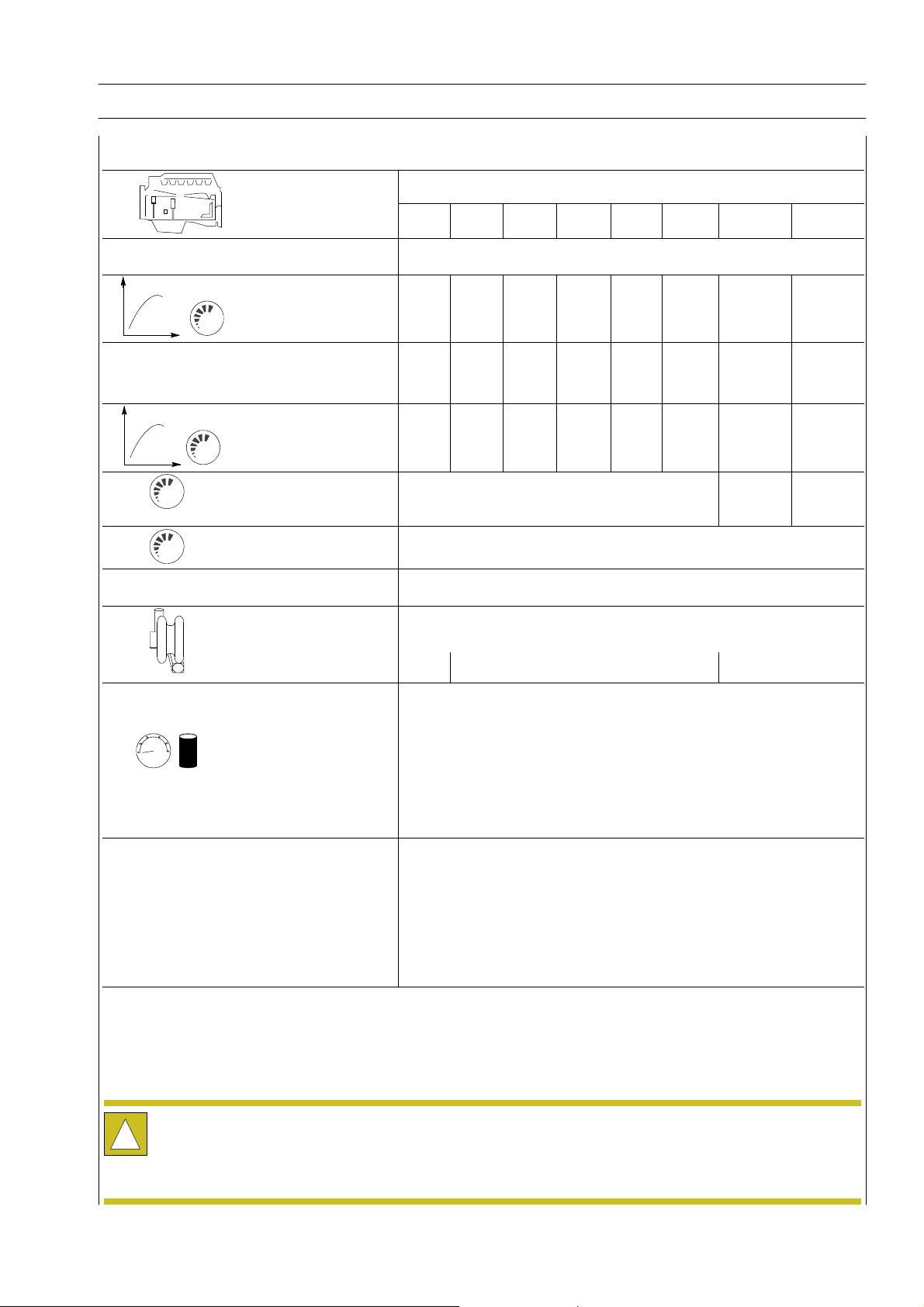
F2C CURSOR ENGINES
Typ
CLEARANCE DATA
SECTION 3 - INDUSTRIAL APPLICATION 3
F2CE9684
e
A*E004
B*E001 C*E001 D*E001 C*E002 E*E002 H*E003 L*E005
¸
Compression ratio 16.5:1
Max. output kW
(HP)
rpm
Peak power kW
(HP)
rpm
Max. torque Nm
(kgm)
rpm
Loadless
engine
idling rpm
Loadless engine
peak rpm
Borexstroke mm
Displacement cm
SUPERCHARGING Intercooler
Turbocharger type HX55 HX40 HX55
3
260
(314)
2100
290
1800
1600
1500
240
(318)
2100
268
1800
1477
1500
220
(299)
2100
245
1800
1355
1500
210
(286)
2100
234
1800
1293
1500
1000 r 25 800 r 25 1000 r 25
220
(299)
2100
245
1800
1355
1500
2100
117 x 135
8710
Direct injection
200
(272)
2100
223
1800
1232
1500
260
(364)
2100
290
1800
1600
1500
279
(353)
2100
290
1800
1600
1500
LUBRICATION
bar
Data, features and performances are valid only if the setter fully complies with all the installation prescriptions provided
by Iveco Motors.
!
Furthermore, the users assembled by the setter shall always be in conformance to couple, power and number of turns
based on which the engine has been designed.
Oil pressure
(warm engine)
- idling bar
- peak rpm bar
COOLING
Water pump control
Thermostat
- start of opening ºC
Forced by gear pump, relief valve single action
oil filter
4
5
Liquid
Through belt
81
Print P2D32C004E Base - June 2006
Page 48

4
SECTION 3 - INDUSTRIAL APPLICATION
F2C CURSOR ENGINES
Base - June 2006 Print P2D32C004E
Page 49

F2C CURSOR ENGINES
SECTION 3 - INDUSTRIAL APPLICATION 5
PART ONE -
MECHANICAL COMPONENTS
Print P2D32C004E Base - June 2006
Page 50

6
SECTION 3 - INDUSTRIAL APPLICATION
F2C CURSOR ENGINES
Base - June 2006 Print P2D32C004E
Page 51
F2C CURSOR ENGINES
SECTION 3 - INDUSTRIAL APPLICATION 7
540110 ENGINE DISASSEMBLY ON
BENCH
NOTE
Before installing engine on rotary stand 99322230,
remove parts that might interfere with the
installation of brackets 99361042.
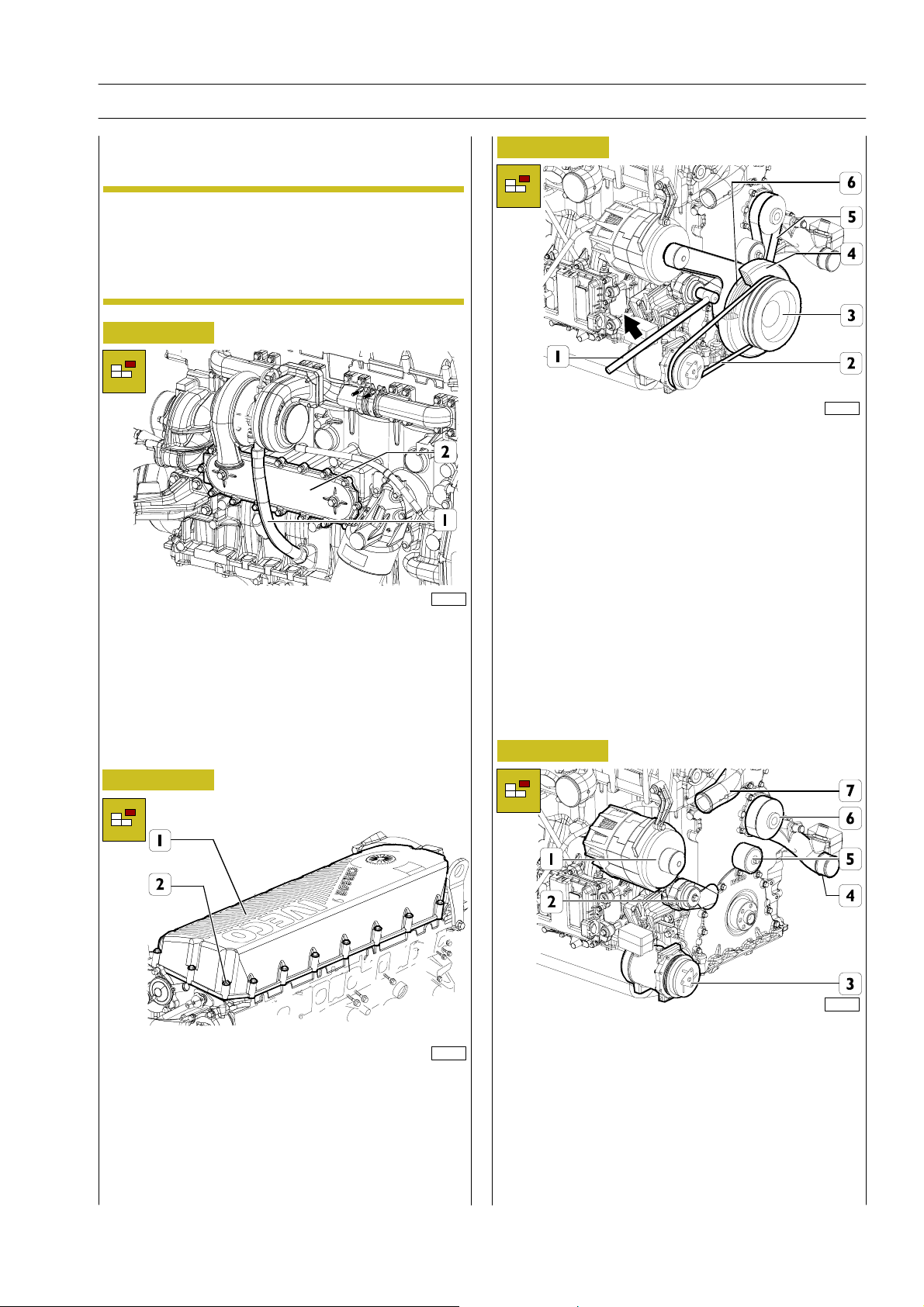
Therefore, remove heat exchanger and oil line as
shown below.
Figure 1
Figure 3
114007
If air conditioner compressor is installed, cut belt (2) as it must
not be reused.
Use specific tool (1) and operate in the arrow direction to
remove water pump and alternator control belt (5).
Remove screws and separate pulleys (3) and (6) with damping
flywheel (4).
114017
Under heatexchanger (2) placea container for engine coolant
drain.
Unlock retaining screws and remove heat exchanger assembly
(2).
Remove oil outlet line (1).
Install engine on rotary stand 99322230.
Drain sump oil in specific container.
Figure 2
114016
Unlock retaining screws (2) and remove head cover (1) to
reach injector and rail wiring.
Remove wiring from all components shown in “Electric
equipment“ section.
Figure 4
114008
Remove parts below:
- alternator (1);
- belt tensioner (2);
- if present, air conditioner compressor (3);
- water pump (6);
- flanged pipe (4);
- fixed belt tensioner (5);
- thermostat assembly (7).
Print P2D32C004E Base - June 2006
Page 52
8
SECTION 3 - INDUSTRIAL APPLICATION
F2C CURSOR ENGINES
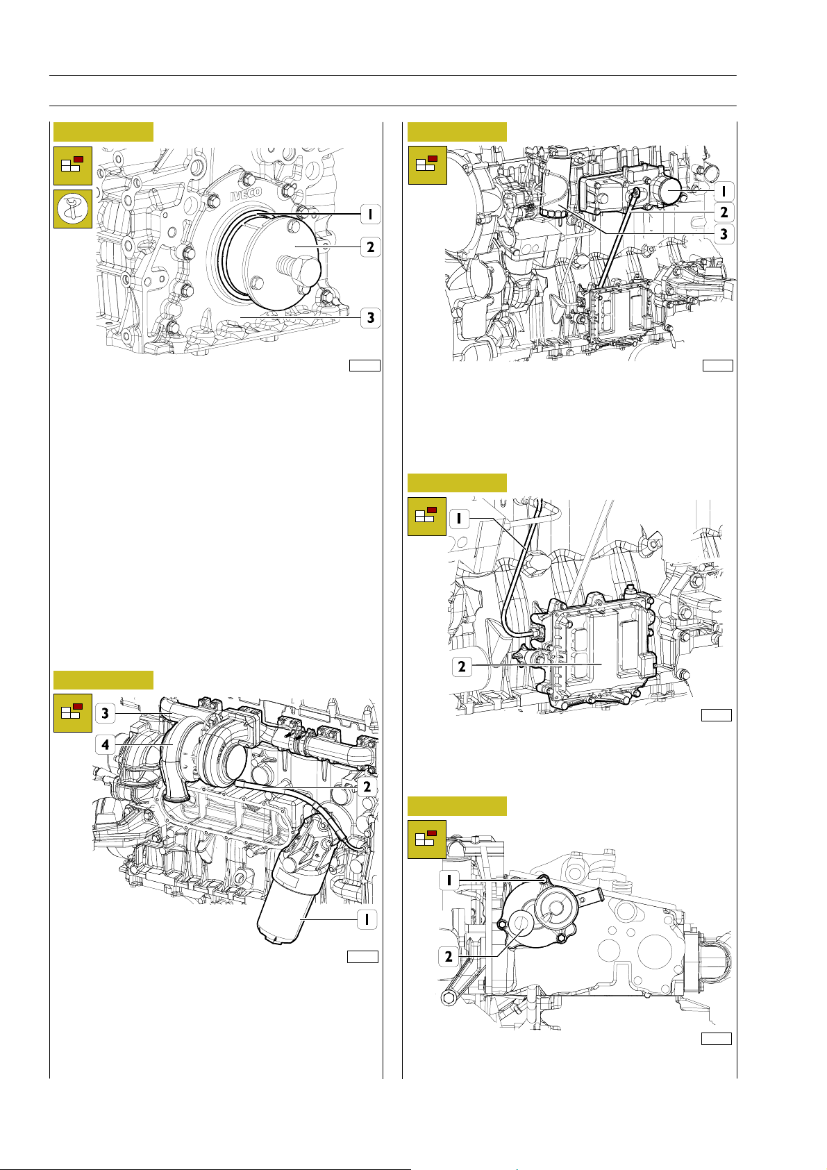
Figure 5
Apply extractor 99340051 (2) and remove seal (1).
Unlock screws and remove front cover (3).
114551
Figure 7
114012
Remove parts below:
- fuel filter (3);
- oil level rod (2);
- intake manifold (1).
Figure 8
Figure 6
Remove parts below:
- oil filter (1);
- oil inlet line (2);
- turbocompressor (4) and exhaust manifold (3).
On opposite engine side, remove start-up motor.
114013
Disconnect line (1) from high pressure pump support and
remove ECU (2) with support below.
Figure 9
114010
114015
Remove screws (1) and blow-by box (2).
Base - June 2006 Print P2D32C004E
Page 53
F2C CURSOR ENGINES
SECTION 3 - INDUSTRIAL APPLICATION 9
Figure 10
114018 114014
Unlock screws (1) and remove cover (2). Remove centrifugal
filter (3) below.
Figure 12
Disconnect fuel lines (2), unlock retaining screws and remove
high pressure pump (1). Remove fuel filter support (3)
complete with pipeline.
Figure 13
Figure 11
114019
Use specific spanner to unlock screws (2) and remove gear (3)
complete with tune wheel.
Unlock nut (4) and remove control gear (5) of high pressure
pump.
Remove rpm sensor (1).
NOTE
In case removal of gear (5) is difficult, release high
pressure pump screws with light beater strokes on
control shaft and remove gear (5).
114020
Unlock screws (1) and remove thrust plate (2).
Use specific spanner to unlock screws (4) and remove relay
gear (5).
Remove high pressure pump mount flange (3).
Figure 14
114009
Use specific tool lock engine flywheel (2) rotation, unlock
retaining screws (1) and remove engine flywheel.
Print P2D32C004E Base - June 2006
Page 54
10
SECTION 3 - INDUSTRIAL APPLICATION
F2C CURSOR ENGINES
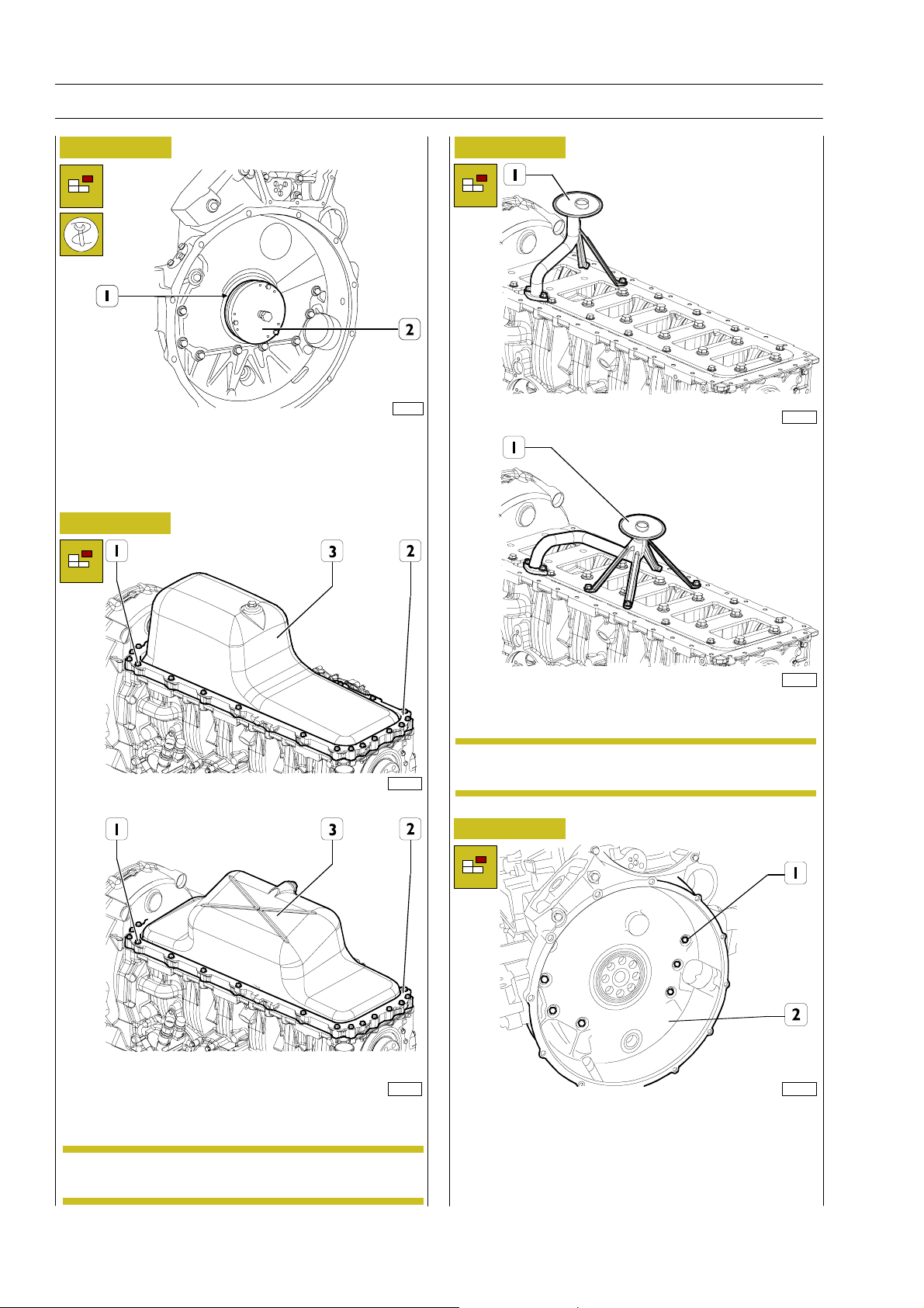
Figure 15
Apply extractor 99340054 (2) and remove seal (1).
Figure 16
45257
Figure 17
114031
114256
114029
Unlock screws (1) and remove engine oil sump (3) complete
with spacer (2) and seal.
114031b
Unlock screws and remove suction rose (1).
Suction rose shape depends on application type.NOTE
Figure 18
114022
Unlock screws (1) and remove flywheel box (2).
Sump shape depends on application type.NOTE
Base - June 2006 Print P2D32C004E
Page 55
F2C CURSOR ENGINES
SECTION 3 - INDUSTRIAL APPLICATION 11
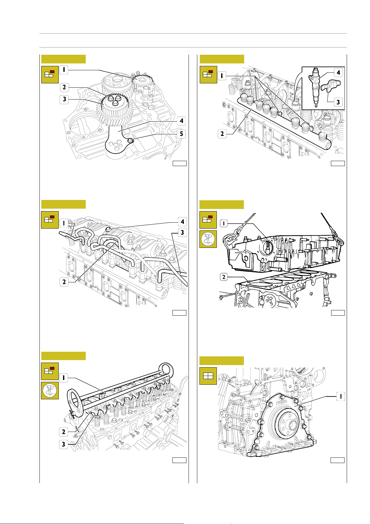
Figure 19
Remove screws (2) and double gear (3).
Remove retaining screw (5) and connecting rod (4).
Remove oil pump (1).
Figure 20
114023
Figure 22
114027
Remove retaining brackets (3) and remove injectors (4).
Remove retaining screws (1) and remove rail (2).
Figure 23
114024
- Unlock rocker arm shaft retaining screws (4).
- Disconnect fuel pipelines (1) from injector rail, fuel supply
Remove camshaft and remove cylinder head retaining screws.
Use metallicropes to lift cylinder head(1) and remove seal (2).
45266
line (2) of high pressure pump to rail and return line (3).
Figure 21
114025
Apply tool 99360558 (1) to rocker arm shaft and remove
shaft, remove crosspieces (3) from cylinder head.
Print P2D32C004E Base - June 2006
ASSEMBLY
Figure 24
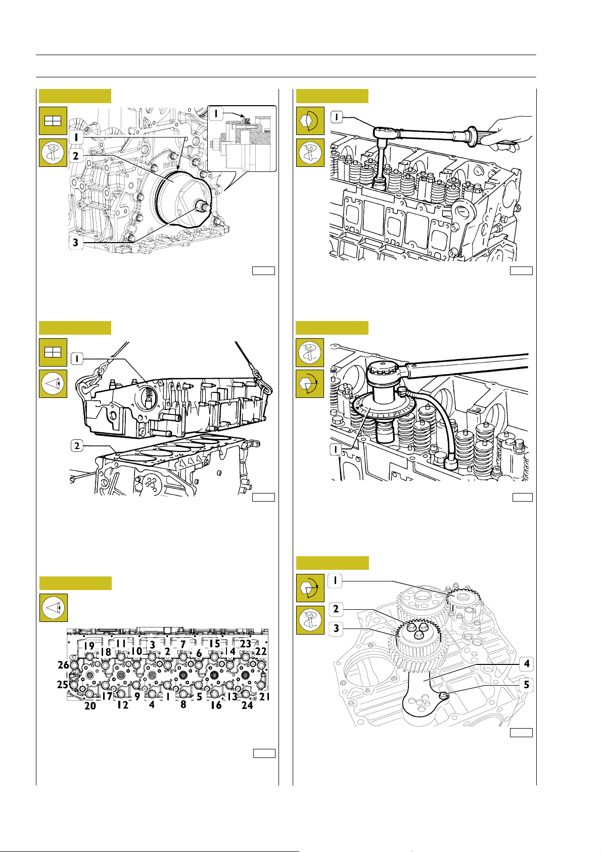
114257
Install front cover (1) and lock retaining screw at required
torque.
Page 56
12
SECTION 3 - INDUSTRIAL APPLICATION
F2C CURSOR ENGINES
Figure 25
114258
Secure seal (1), install special tool 99346260 (2), lock nut (3)
to secure seal (1).
Figure 26
Figure 28
- Pre-lock by torque wrench (1):
st
phase: 50 Nm (5 kgm);
1
nd
phase: 100 Nm (10 kgm).
2
Figure 29
45267
42566
Check that pistons 1-6 are exactly at T.D.C.
Place seal (2) on cylinder block.
Install cylinder head (1) and lock screws as shown in figures
below.
Figure 27
§
- Angle locking by means of tool 99395216 (1):
rd
3
phase: 90q angle
th
phase: 75q angle.
4
Figure 30
§
45268
114023
114259
Cylinder head retaining screw locking sequence diagram.
Install oil pump (1), double gear (3) complete with connecting
rod(4)andlockscrews(2)intwophases:
pre-lock 30 Nm
90q angle lock
Base - June 2006 Print P2D32C004E
Page 57
F2C CURSOR ENGINES
Figure 31
SECTION 3 - INDUSTRIAL APPLICATION 13
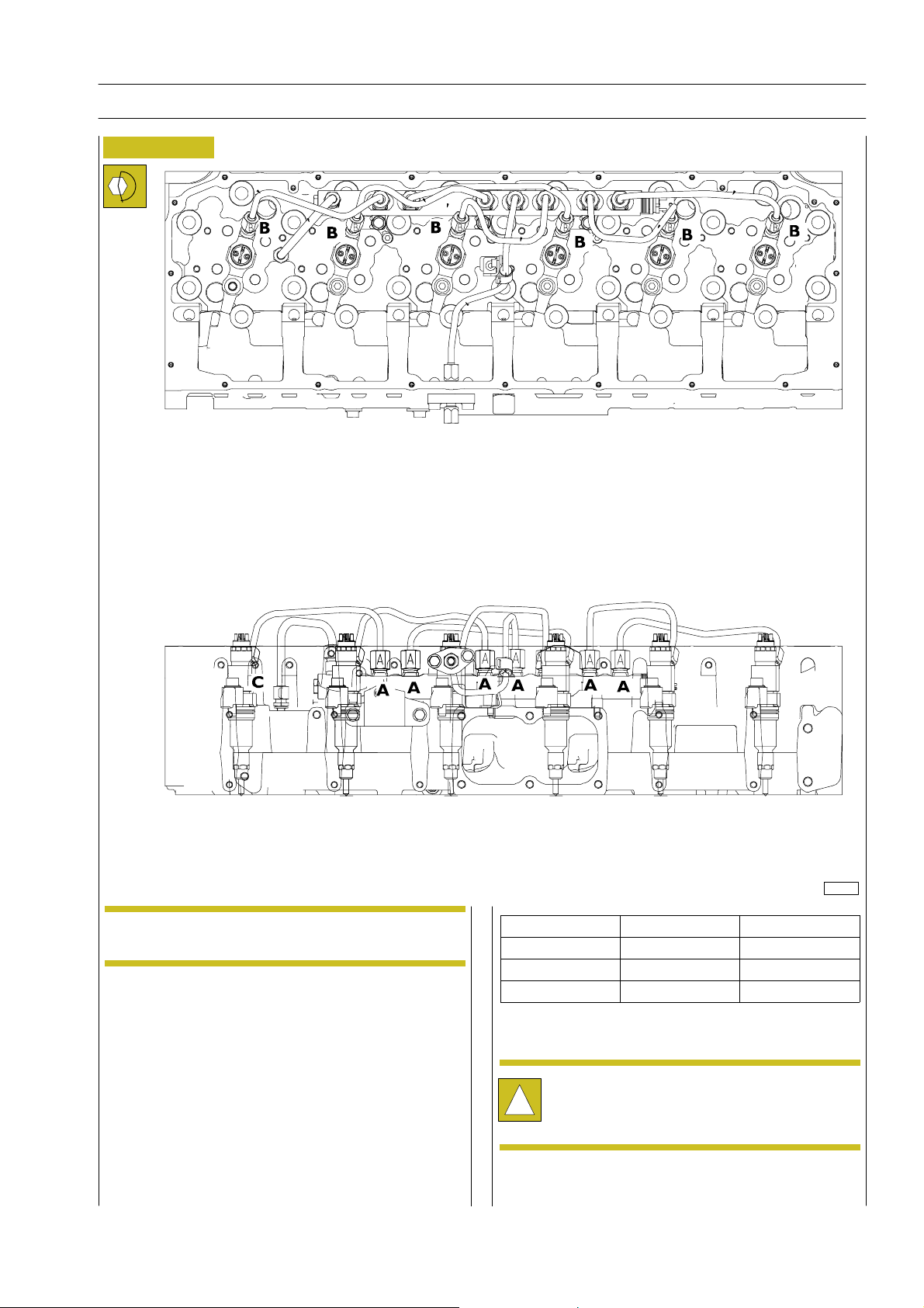
114260
NOTE
The previously removed pipes ca no longer be refit
and must be replaced.
TYPE DESCRIPTION LOCK TORQUE
A M18 x 1.5 40 r 2Nm
B M14 x 1.5 35 r 2Nm
1. Install rail on cylinder head and lock retaining screws by
hand.
C M16 x 1.5 40 r 2Nm
2. Install injectors in correct position and lock to required
torque.
3. Install pipes on rail and lock fittings by hand.
4. Lock rail to cylinder head retaining screws at required
torque.
After fitting the high-pressure pipelines, during the
following 20 hours of work, frequently check engine
!
oil level (IT MUST NOT INCREASE).
5. Fit pipes on injectors and head locking fittings by hand.
6. Lock fittings on rail (A, C) at required torque .
7. Lock fittings on injectors and head (B, C) at required
torque.
Print P2D32C004E Base - June 2006
Page 58
14
SECTION 3 - INDUSTRIAL APPLICATION
F2C CURSOR ENGINES
Figure 32
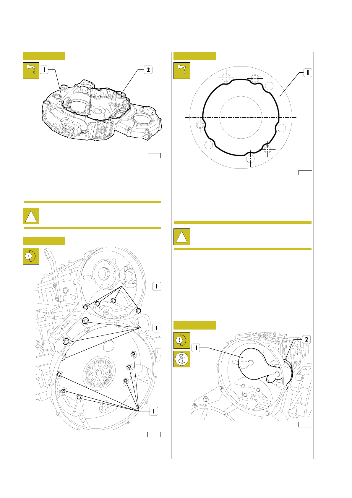
114261
Clean surfaces to be coupled to remove dirt and oil residuals.
Apply LOCTITE 275 silicone on gear casing (1) as shown in
the figure.
The sealant seam diameter must be 1.5 r 0.5/0.2.
Install gear casing within 10 min. from sealant
application.
!
Figure 34
114263
Clean surfaces to be coupled to remove dirt and oil residuals.
Apply LOCTITE 275 silicone on gear casing (1) as shown in
the figure.
The sealant seam diameter must be 1.5 r 0.5/0.2.
Figure 33
Install gear casing within 10 min. from sealant
application.
!
Figure 35
114264
114262
Use torque wrench to lock screws (1) at required torque.
Apply gage 99395221 (1) to check and adjust position of
high-pressure pump connection flange (2).
Fixflangescrews(2)atrequiredtorque.
Base - June 2006 Print P2D32C004E
Page 59
F2C CURSOR ENGINES
SECTION 3 - INDUSTRIAL APPLICATION 15
High pressure pump installation
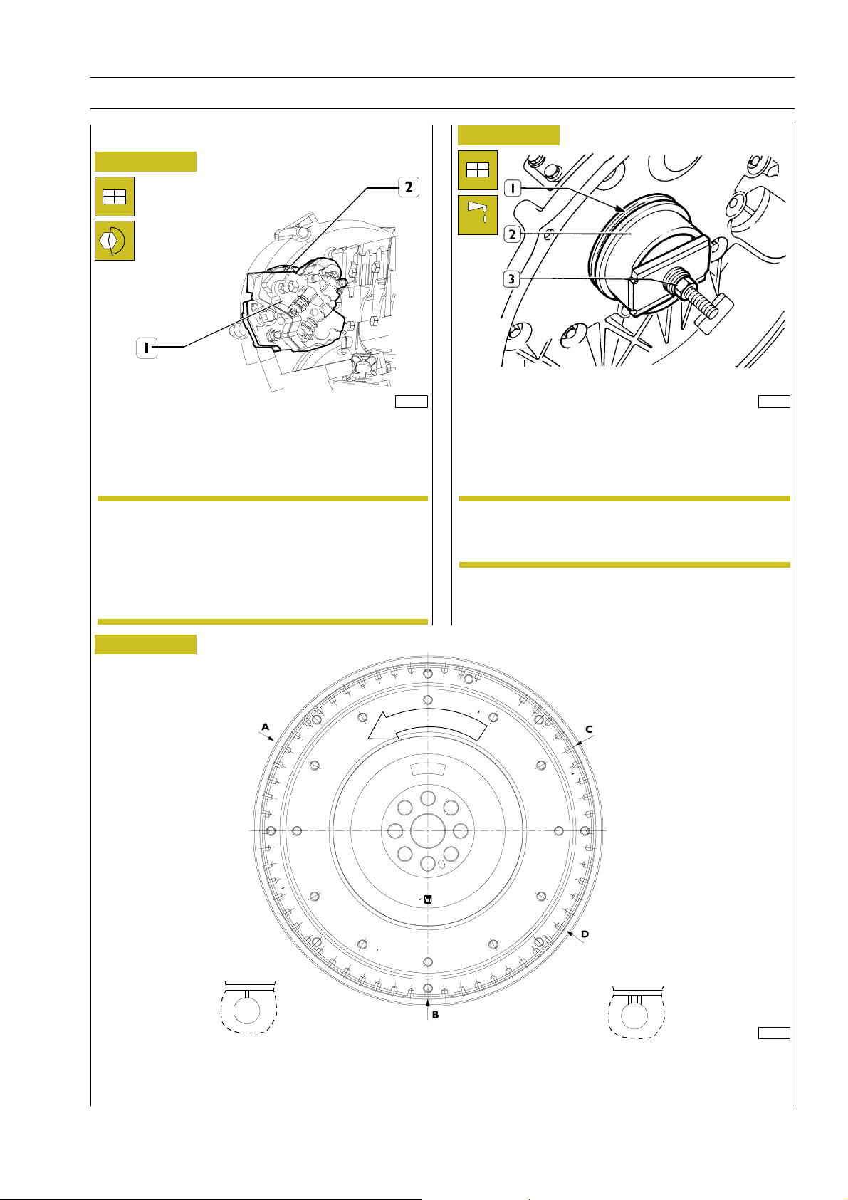
Figure 36
Install high-pressure pump (1) on flange (2).
540850 ENGINE FLYWHEEL
NOTE
If toothing on engine flywheel for engine start-up is
very damaged, change crown wheel.
Refit crown wheel after heating up at approx.
200qC.
114272
Figure 37
45258
Secure seal (1), install special tool 99346260 (2), lock nut (3)
to secure seal.
Engine flywheel installation
NOTE
Crankshaft has a reference pin that must match with
related housing on engine flywheel.
Figure 38
114265
DETAIL OF PISTON POSITION STAMPING ON ENGINE FLYWHEEL
A. Hole on flywheel with a notch corresponding to pistons 3-4 TDC - B. Hole on flywheel with a notch, corresponding to
piston 1-6 TDC - C. Hole on flywheel with a notch corresponding to pistons 2-5 TDC - D. Hole on flywheel with 2 notches,
position corresponding to 54q.
Print P2D32C004E Base - June 2006
Page 60
16
SECTION 3 - INDUSTRIAL APPLICATION
F2C CURSOR ENGINES
Figure 39
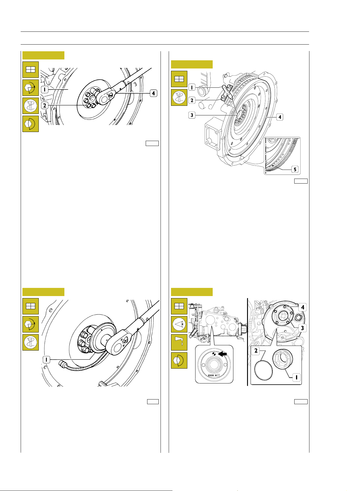
§
49037
Position flywheel (1) on crankshaft, lubricate screws (2)
threading with engine oil and lock them.
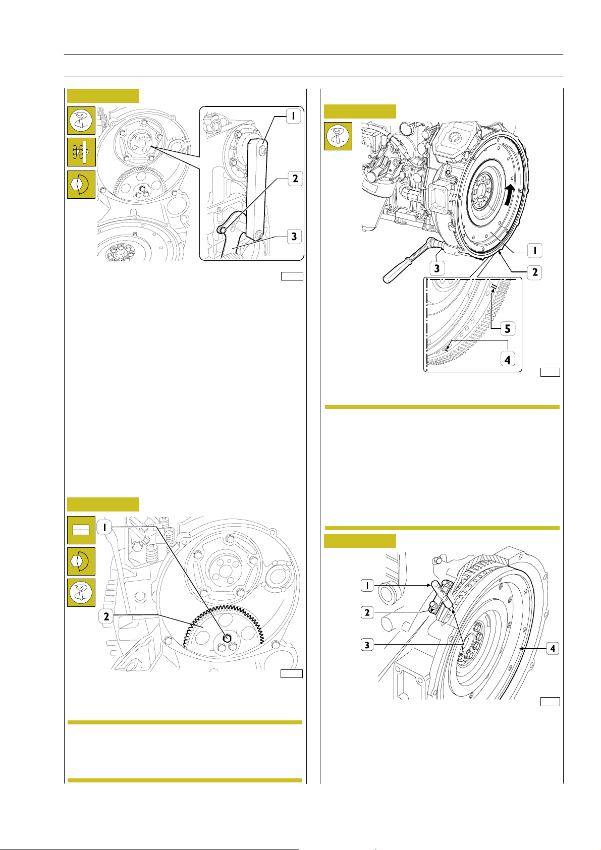
Stop rotation using specific tool.
Lock screws (2) in three phases.
st
phase: pre-lock with torque wrench (4) at 100 Nm torque
1
(10 kgm).
Camshaft installation
Figure 41
72436
Position crankshaft with pistons 1 and 6 at TDC.
This condition is obtained when:
1. hole with notch (5) of engine flywheel (4) is visible
through manhole;
2. tool 99360612 (1), through housing (2) of engine rpm
sensor, inserts in hole (3) drilled on engine flywheel (4).
Otherwise, adjust engine flywheel orientation (4).
Remove too 99360612 (1).
Figure 40
Figure 42
§
nd
phase: 60q angle locking using tool 99395216 (1).
2
49036
Install camshaft (3) and orient it with references (o)
114267
positioned as in the figure.
Install thrust plate (1) with seal (2) and lock screws (4) at
required torque.
Base - June 2006 Print P2D32C004E
Page 61
F2C CURSOR ENGINES
SECTION 3 - INDUSTRIAL APPLICATION 17
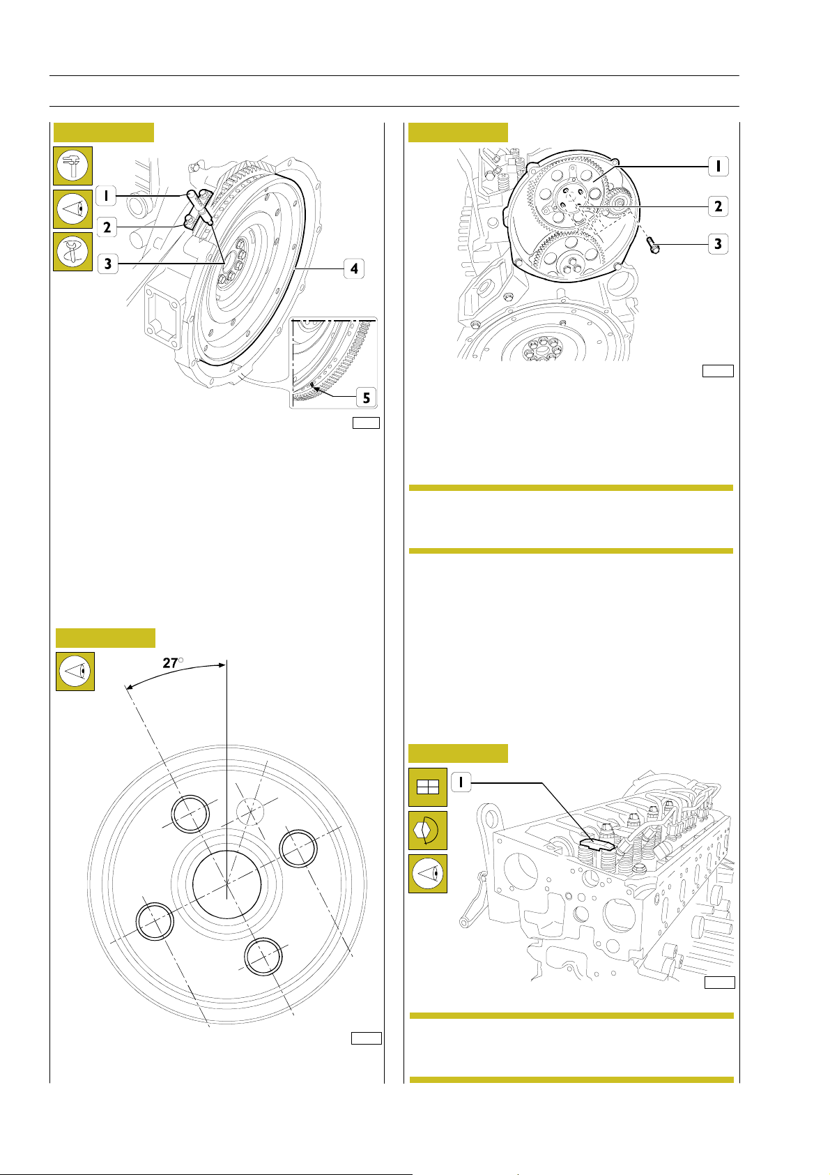
Figure 43
114269
Apply gage 99395222 (1), check and adjust position of
connecting rod (3) for relay gear, lock screw (2) at required
torque.
Camshaft tuning
Figure 45
114279
Figure 44
114270
Refit relay gear (2) and lock screws (1) using six-splined
spanner at required torque.
NOTE
The relay gear (1) bushing can be replaced when
worn out. After securing bushing, grind it to reach
dia. 58.010 r 0.10 mm.
Secure special tool 99360641 (3) to gear casing.
NOTE
The arrow indicated engine rotation direction.
Use tool above to rotate engine flywheel (1) in
engine rotation direction to bring cylinder 1 piston
approx. to TDC in blast phase.
This condition is reached when hole with notch (4),
following hole with two notches (5) drilled on
engine flywheel (1), is visible through manhole (2).
Figure 46
71774
The exact position of piston no.1 at TDC is obtained when,
in conditions described above, tool 99360612 (1), through
engine rpm sensor housing (2), inserts in hole (3) drilled on
engine flywheel (4).
Otherwise, rotate engine flywheel (4) to adjust its orientation.
Remove tool 99360612 (1).
Print P2D32C004E Base - June 2006
Page 62
18
SECTION 3 - INDUSTRIAL APPLICATION
F2C CURSOR ENGINES
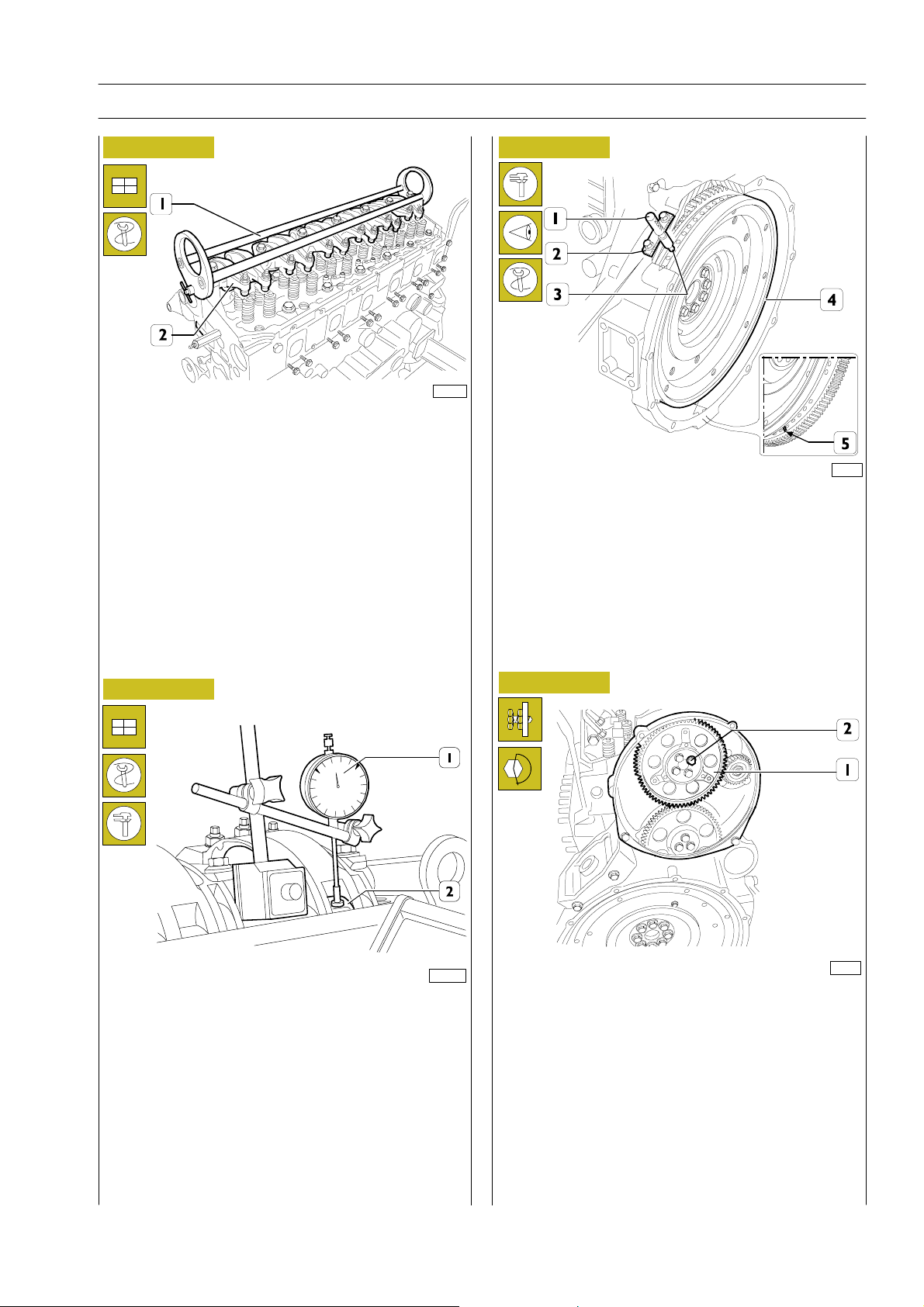
Figure 47
115064
Rotate crankshaft to check conditions below:
1) hole identified with two notches (5) is visible through
manhole;
2) fixture 99360612 (1) through housing (2) of engine rpm
sensor inserts in hole (3) on engine flywheel (4).
Figure 49
114282
Install gear (1) controlling camshaft so that fastening holes on
shaft coincide with slots (2) on control gear.
Lock retaining screws (3).
NOTE
Check that camshaft has maintained position shown
in Figure 48.
Figure 48
115063
Rotate camshaft by 27q in anticlockwise direction as shown in
the figure.
Figure 50
Install crosspieces (1) on valve rod.
NOTE
Before refitting rocker arm shaft assembly, check
that all adjustment screws have been fully unlocked.
114276
Base - June 2006 Print P2D32C004E
Page 63
F2C CURSOR ENGINES
SECTION 3 - INDUSTRIAL APPLICATION 19
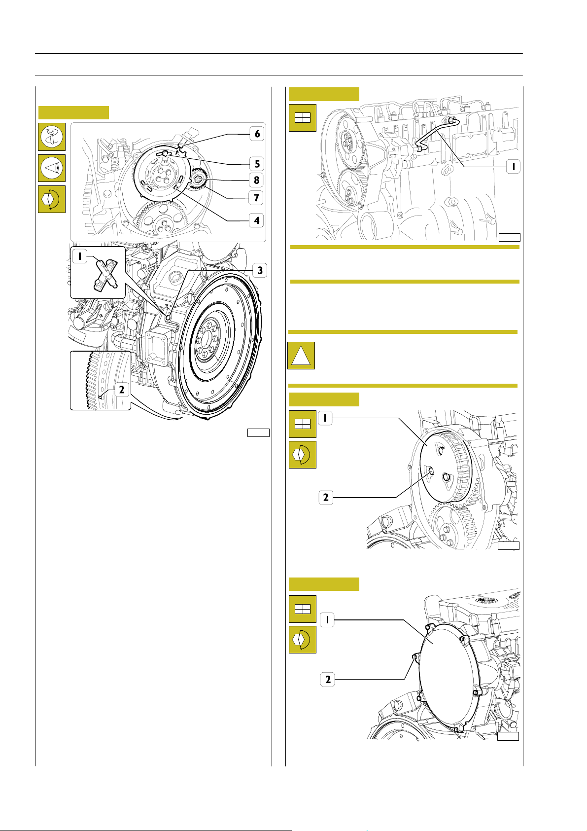
Figure 51
114025
Apply tool 99360558 (1) to rocker arm shaft (2) and install
shaft on cylinder head.
Lock retaining screws at required torque.
Figure 53
115064
Camshaft is timed if conditions below are found at cam lift
values 4.70 r 0.05:
1) hole identified with two notches (5) is visible through
manhole;
2) fixture 99360612 (1) through housing (2) of engine rpm
sensor inserts in hole (3) on engine flywheel (4).
Figure 52
106535
Place dial gage on magnetic base (1) with rod placed on roller
(2) of rocker arm controlling cylinder no.3 exhaust valve and
apply 6 mm preload.
Using tool 99360341 (3, Figure 45), rotate crankshaft
clockwise till dial gage arrow reaches minimum value (max
cam lift), after which it no longer varies.
Zero set dial gage.
Rotate engine flywheel anticlockwise till dial gage reads
camshaft cam lift value = 4.70 r 0.05 mm.
Figure 54
114281
In case conditions shown in Figure 53 and shown at paras 1
and 2 are not found, operate as follows:
1) release screws (2) securing gear (1) of camshaft to as to
make control gear and camshaft independent;
2) conveniently operate on engine flywheel so as to obtain
conditions indicated at paras 1 and 2, Figure 53,
considering that cam lift value must remain unchanged;
3) lock screws (2) and repeat control as already described;
4) lock screws (2) at required torque.
Print P2D32C004E Base - June 2006
Page 64
20
SECTION 3 - INDUSTRIAL APPLICATION
F2C CURSOR ENGINES
Tune wheel timing
Figure 55
Figure 56
114275
NOTE
Pipes previously removed ca no longer be refit.
Change them.
Install fuel supply pipeline (1) from high pressure pump to rail.
Lock nuts at 35 Nm torque.
After high-pressure pipe installation, during the
following 20 hours of work, frequently check engine
!
oil level (IT MUST NOT INCREASE).
114284
Install gear (7) of high pressure pump and lock nut (8) at
required torque.
Install tune wheel (4).
Rotate crankshaft and bring cylinder n.1 piston to compression
phase at TDC: Rotate flywheel opposite to regular rotation
direction by 1/4 of rev.
Rotate flywheel again in regular rotation direction till hole
identified by double notch (2) shows through inspection hole
under flywheel cover box.
Insert tool 99360612 (5) in flywheel sensor housing.
Insert tool 99360613 through phase sensor housing (6) on
tooth machined on tune wheel.
In casetool (6) is difficult toinsert, unlock screws (5) and orient
tune wheel (4) to properly match the tooth.
Lock screws (5).
Figure 57
114285
Install centrifugal filter (1) on tune wheel and l ock screws (2)
at required torque.
Figure 58
114286
Install timing cover (1) and lock retaining screws (2) at
required torque.
Base - June 2006 Print P2D32C004E
Page 65
F2C CURSOR ENGINES
SECTION 3 - INDUSTRIAL APPLICATION 21
Intake and exhaust rocker arm clearance
adjustment
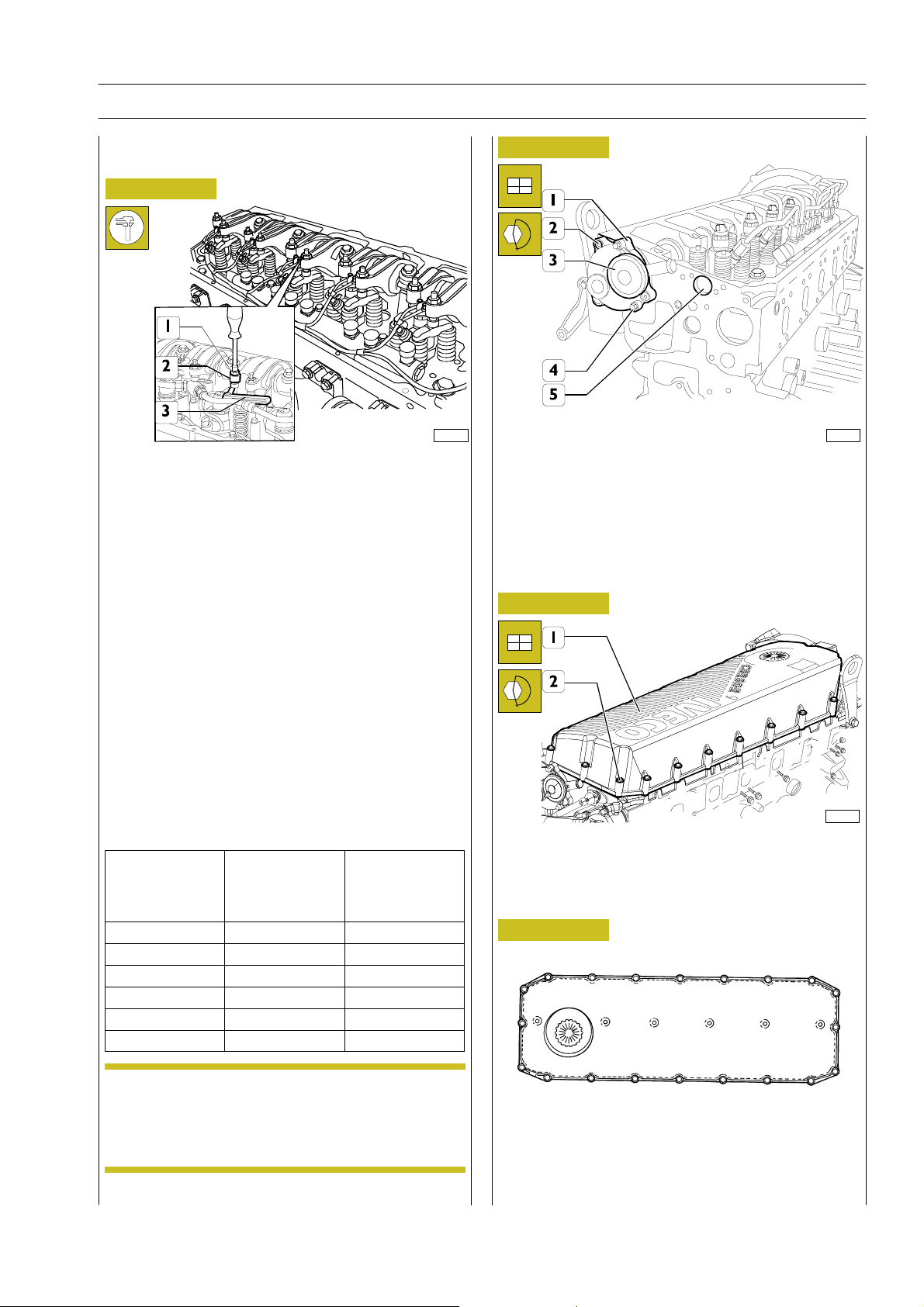
Figure 59
114287
Adjustment of clearance between rocker arms and
intake/exhaust valve control crosspieces must be performed
with utmost care. Bring to blast phase cylinder to be adjusted;
the valves of this cylinder are closed while the symmetric
cylinder valves are balanced. Symmetric cylinders are 1-6; 2-5
and 3-4.
In order to perform these operations correctly, refer to
procedure and table below.
- Use a polygonal spanner to release lock nut (1) of rocker
arm adjustment screw (2).
- Insert filler gage (3) having same value of operating
clearance shown in “Characteristic and data“ tables.
- Use special spanner to lock/unlock adjustment screw.
- Check that filler gage (3) slides with a low friction.
- Lock nut (1) retaining the adjustment screw.
Figure 60
114288
Install blow-by body (1) with related seal and lock screws (2)
at required torque.
Install cover (3) and lock screws (4) at required torque.
Install wiring harness to injectors and pressure sensor of rail
through hole (5).
Figure 61
114016
IGNITION ORDER 1-4-2-6-3-5
START AND
ROTATION
CLOCKWISE
BALANCE
VALVES OF
CYLINDER No.
ADJUST
CLEARANCE OF
VALVES
Install cylinder head cover (1) and lock screws (2) at required
torque following order shown in Figure 62 diagram.
CYLINDER No.
1and6atTDC 6 1
120q 3 4
120q 5 2
120q 1 6
120q 4 3
120q 2 5
NOTE
In order to correctly carry out adjustments above,
it is mandatory to perform the sequence indicated
Figure 62
17 14 13 1 4 5 8
18
19
20
16 15 12 2 3 6 7
9
10
11
in the table, checking exact positioning at each phase
by means of pin 99360612.
Print P2D32C004E Base - June 2006
Page 66
22
SECTION 3 - INDUSTRIAL APPLICATION
F2C CURSOR ENGINES
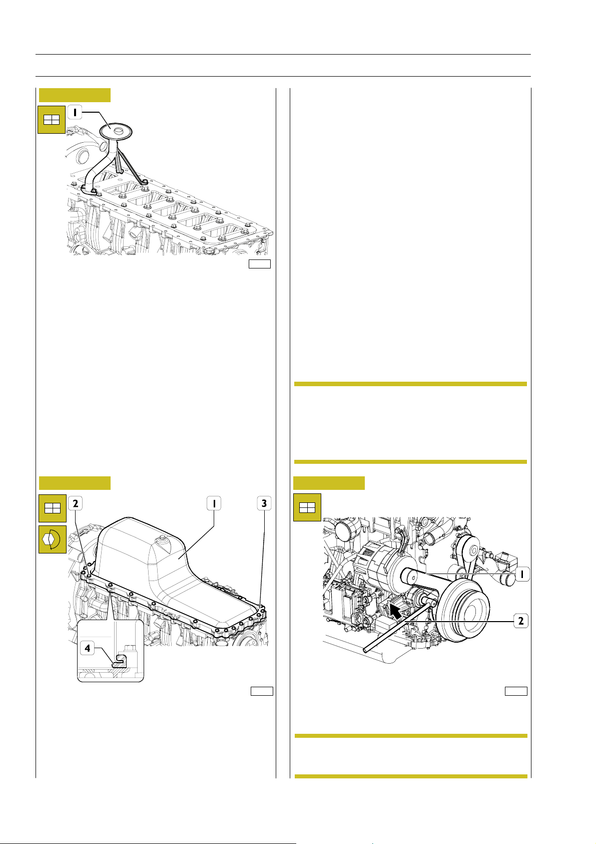
Figure 63
Install suction rose (1).
114031
ENGINE ASSEMBLY COMPLETION
Complete engine assembly fitting or connecting parts below:
- complete fuel filter support and pipelines;
-EDCecu;
- intake manifold with pre-heating resistor;
- heat exchanger;
- exhaust manifold;
- turbocharger and related water and oil;
- pulley and damper flywheel assy (install fixed guide pulley
5, Figure 3, before assy);
- thermostat assy;
- belt tensioner, water pump, alternator;
- oil level rod;
- start-up motor;
- oil filter;
- electric connections and sensors.
Figure 64
NOTE
Figure 65
Fittings of pipelines, cooling water and turbocharger
lube oil must be locked at:
-35r 5Nm, water pipeline fittings;
-55r 5Nm, oil pipeline female fitting;
- 20-25 Nm, oil pipeline make fitting.
114290
Rotate engine.
Fit seal (4) on oil sump (1), fit spacer (3) and install sump on
Use specific equipment (2) to install belt (1) on belt tensioner,
in direction shown by arrow.
114291
engine block locking screws (2) at required torque.
NOTE
Belt tensioner is automatic, therefore no further
adjustments are required after installation.
Base - June 2006 Print P2D32C004E
Page 67
F2C CURSOR ENGINES
SECTION 3 - INDUSTRIAL APPLICATION 23
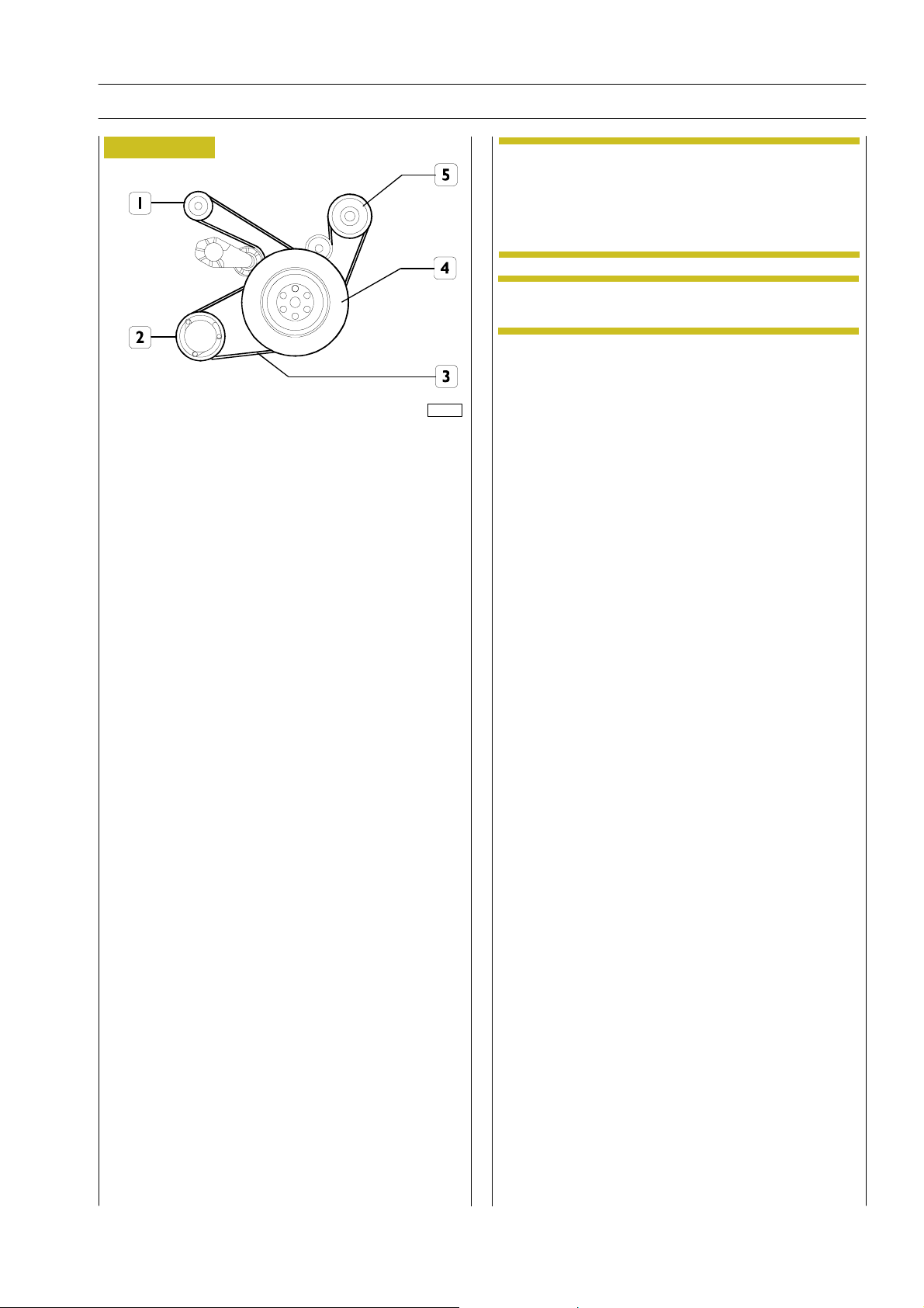
Figure 66
114292
COMPRESSOR CONTROL ELASTIC BELT
INSTALLATION DIAGRAM
1. Alternator - 2. Air conditioner compressor -
3. Elastic belt - 4. Crankshaft - 5. Water pump
Install the conditioner compressor ( 2) and lock retaining
screws at required torque.
Install elastic belt (3) on crankshaft pulley.
Fit belt on air conditioner pulley queue (2).
Use specific tool to rotate crankshaft in order to fit belt on
conditioner pulley.
NOTE
During operation, conveniently guide belt to
prevent torsions/tensions that might adversely
affect it.
Possibly place a bit of rubber between pulley and
belt.
NOTE
Elastic belt must be replaced with a new one after
each disassembly operation.
Refill engine with required quantity of oil.
Remove engine from stand and fit heat exchanger with
turbocharger oil drain pipeline.
Print P2D32C004E Base - June 2006
Page 68

24
SECTION 3 - INDUSTRIAL APPLICATION
F2C CURSOR ENGINES
Base - June 2006 Print P2D32C004E
Page 69

F2C CURSOR ENGINES
SECTION 3 - INDUSTRIAL APPLICATION 25
PART TWO -
ELECTRICAL EQUIPMENT
Print P2D32C004E Base - June 2006
Page 70

26
SECTION 3 - INDUSTRIAL APPLICATION
F2C CURSOR ENGINES
Base - June 2006 Print P2D32C004E
Page 71
F2C CURSOR ENGINES
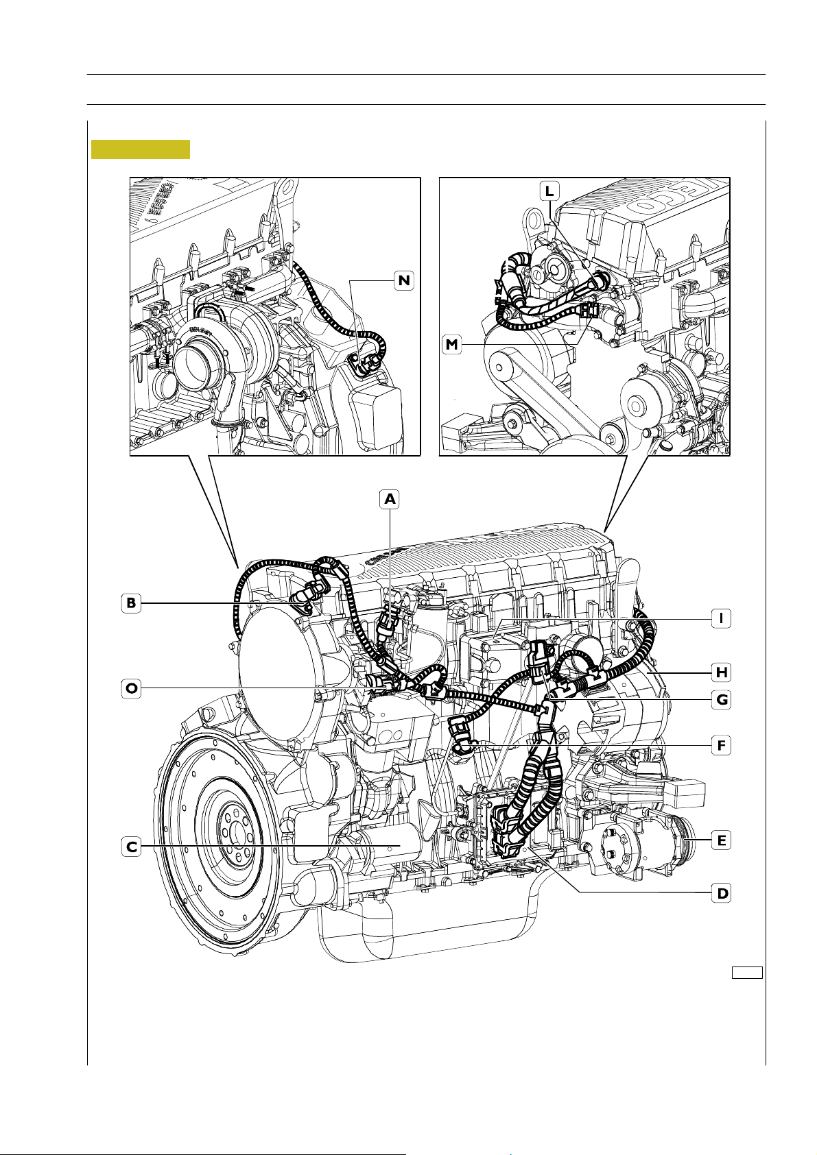
Components on the engine F2C
Figure 1
SECTION 3 - INDUSTRIAL APPLICATION 27
114294
A. Fuel temperature sensor - B. Engine rpm sensor on camshaft - C. Starter motor - D. EDC 7 control unit - E. Conditioner
compressor - F. Pressure/temperature transmitter - G. Temperature/air pressure sensor -
H. Alternator - I. Resistance for engine warming - L. Connector on engine block for connection with electro-injectors -
M. Water temperature sensor - N. Engine speed on flywheel sensor - O. Fuel adjustment valve on high pressure pump
Print P2D32C004E Base - June 2006
Page 72
28
SECTION 3 - INDUSTRIAL APPLICATION
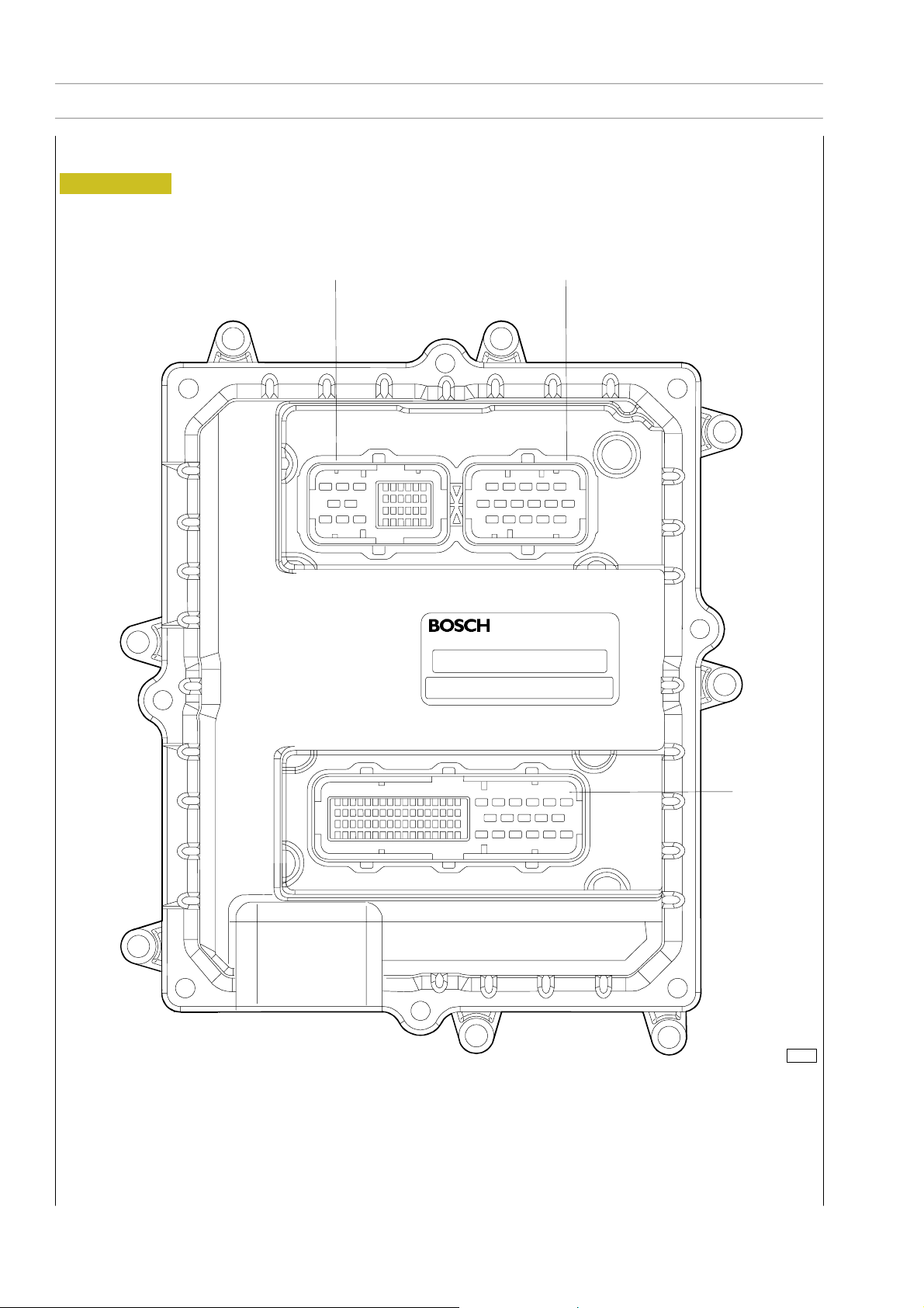
EDC 7 UC31 electronic control unit
Figure 2
F2C CURSOR ENGINES
AC
B
102373
A. Electro-injector connector - B. Chassis connector - C. Sensor connector
Base - June 2006 Print P2D32C004E
Page 73
F2C CURSOR ENGINES
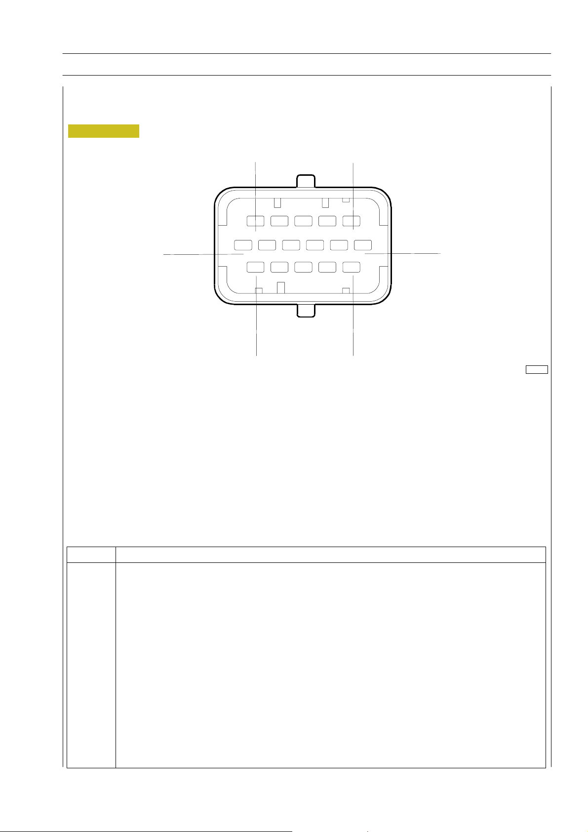
EDC control unit PIN -OUT
Electric injector connector ”A”
Figure 3
SECTION 3 - INDUSTRIAL APPLICATION 29
Colour legend
B black
R red
U blue
W white
P purple
G green
N brown
Y yellow
O orange
E grey
K pink
12
6
1
16
11
5
102374
Pin Function
1 Solenoid valve for electronic cylinder 5 injection
2 Solenoid valve for electronic cylinder 6 injection
3 Solenoid valve for electronic cylinder 4 injection
4 Solenoid valve for electronic cylinder 1 injection
5 Solenoid valve for electronic cylinder 3 injection
6 Solenoid valve for electronic cylinder 2 injection
7 Free
8 Free
9 Fuel high pressure pump
10 Fuel high pressure pump
11 Solenoid valve for electronic cylinder 2 injection
12 Solenoid valve for electronic cylinder 3 injection
13 Solenoid valve for electronic cylinder 1 injection
14 Solenoid valve for electronic cylinder 4 injection
15 Solenoid valve for electronic cylinder 6 injection
16 Solenoid valve for electronic cylinder 5 injection
Print P2D32C004E Base - June 2006
Page 74
30
SECTION 3 - INDUSTRIAL APPLICATION
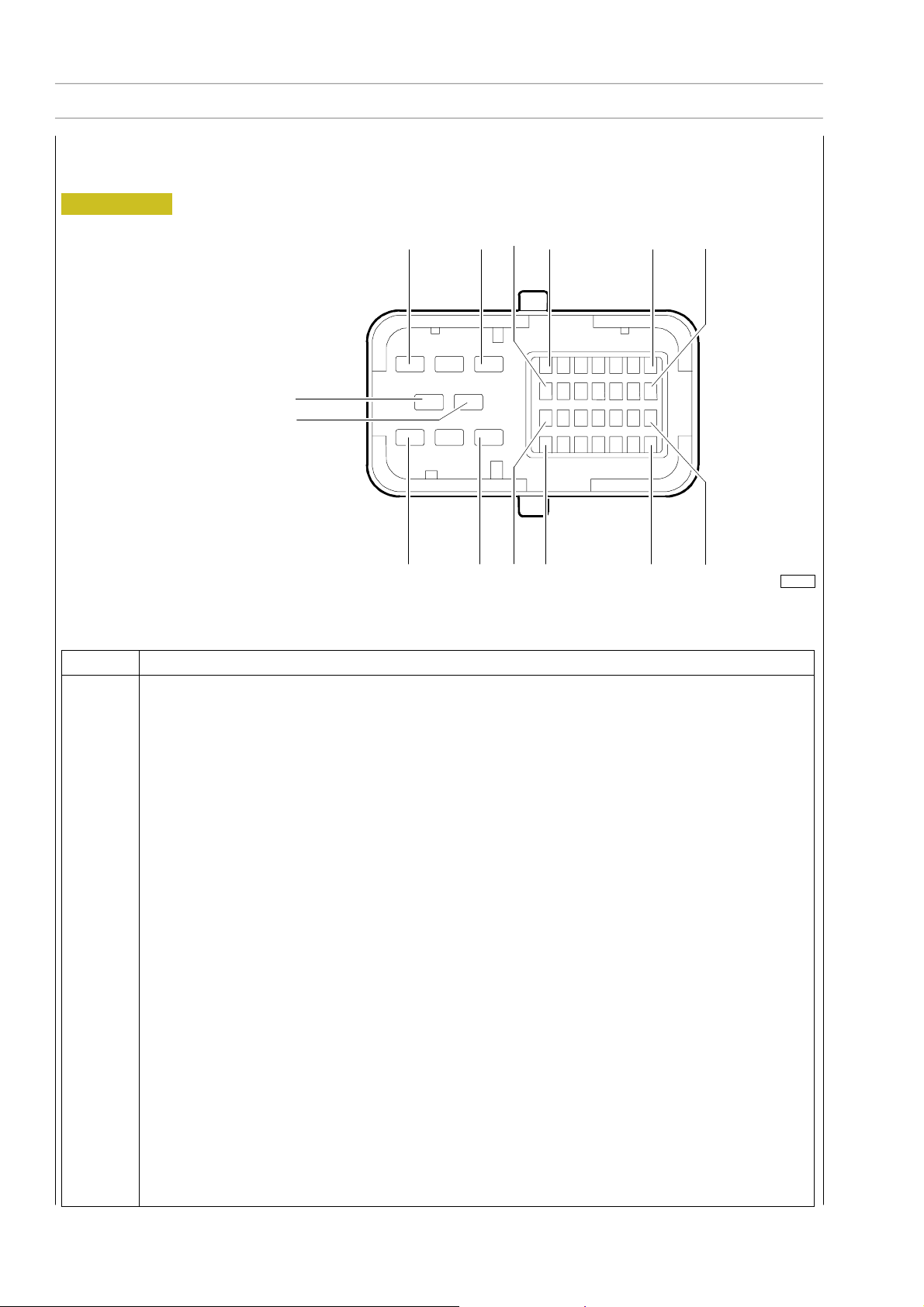
EDC control unit PIN-OUT
Sensor connector ”C”
Figure 4
Colour legend
B black
R red
U blue
W white
P purple
G green
N brown
Y yellow
O orange
E grey
K pink
F2C CURSOR ENGINES
6 8 16 9 15 22
4
5
36 29302331
102375
Pin Function
1y8 N.C.
9 Engine speed sensor (timing)
10 Engine speed sensor (timing)
11 N.C.
12 Pressure sensor on rail
13 Pressure sensor on rail
14 Pressure sensor on rail
15 Coolant temperature sensor
16 N.C.
17 N.C.
18 Fuel temperature sensor
19 Engine speed sensor (flywheel)
20 N.C.
21 N.C.
22 N.C.
23 Engine speed sensor (flywheel)
24 Engine oil pressure/temperature sensor
25 Air pressure/temperature sensor supply
26 Coolant temperature sensor
27 Engine oil temperature/pressure sensor
28 Engine oil temperature/pressure sensor
29 N.C.
30 N.C.
31 N.C.
32 Engine oil temperature/pressure sensor
33 Air pressure signal from air pressure/temperature sensor
34 Air temperature signal from air pressure/temperature sensor
35 Fuel temperature sensor
36 Air temperature signal from air pressure/temperature sensor
Base - June 2006 Print P2D32C004E
Page 75
F2C CURSOR ENGINES
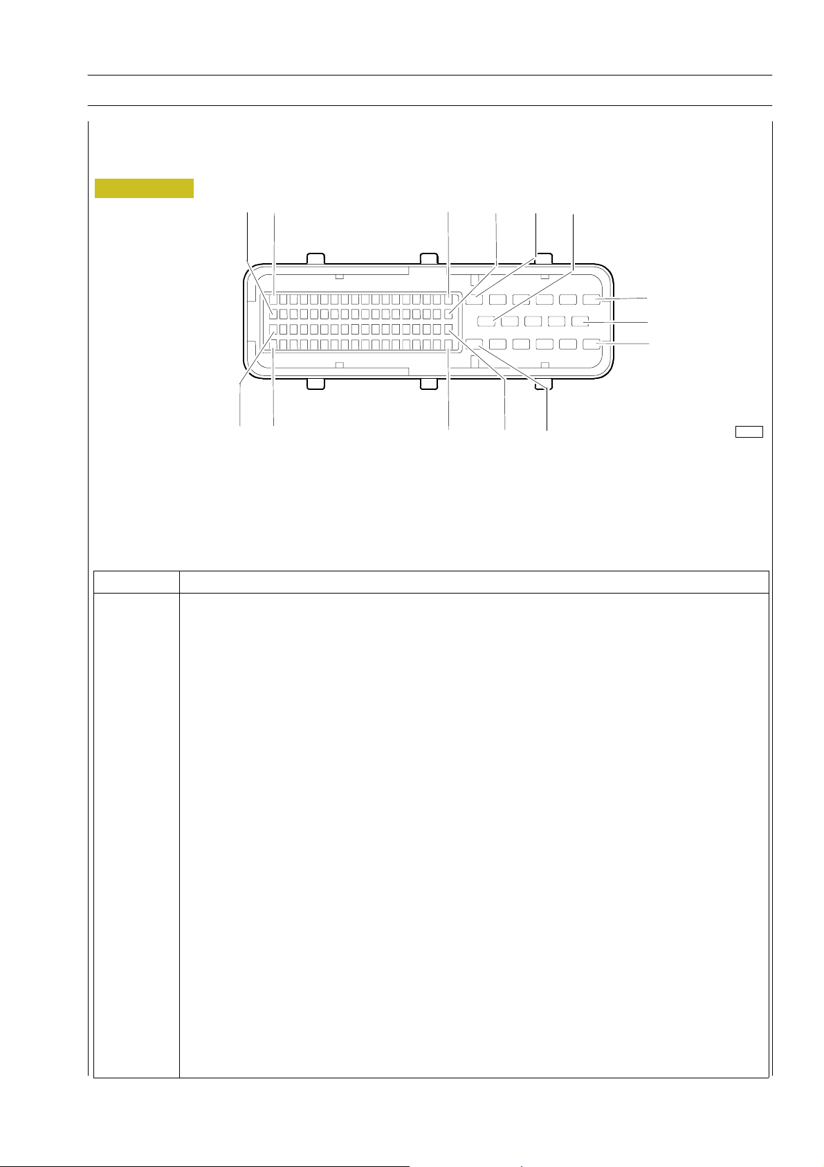
EDC control unit PIN -OUT
Chassis connector ”B”
SECTION 3 - INDUSTRIAL APPLICATION 31
Figure 5
72
18
53
71
89
35
Pin Function
1 --2 Power supply positive (+B)
3 Power supply positive (+B)
4 --5 Power supply negative (-B)
6 Power supply negative (-B)
7 --8 Power supply positive (+B)
9 Power supply positive (+B)
10 Power supply negative (-B)
11 Power supply negative (-B)
12 Pre-heating resistor relay command
13y28 ---
29 EDC system diagnostics switch supply (provision)
30y33 ---
34 CAN L (ECB) line
35 CAN H (ECB) line
36y39 ---
40 Battery positive with key ON
41 --42 Signal in from water present in fuel sensor
43y74 ---
75 Pre-post heating resistor relay positive
76y88 ---
89 ISO “K“ diagnostics line
54
36
6
11
1
7
12
17
102376
Print P2D32C004E Base - June 2006
Page 76
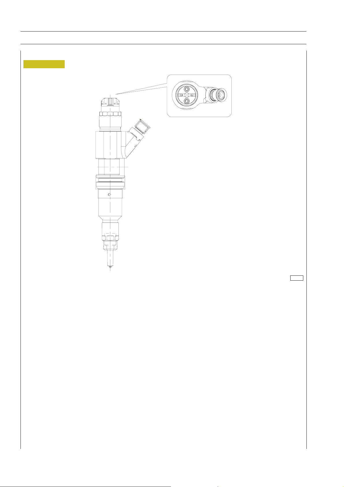
32
SECTION 3 - INDUSTRIAL APPLICATION
Electroinjectors
Figure 6
F2C CURSOR ENGINES
114255
It is a N.O. solenoid valve.
They are connected to the EDC ECU on connector A.
Theresistanceofeachinjectorcoilis0.56-0.57Ohm.
The injector is built like the traditional ones, except for no needle return spring; the electroinjector can be considered as consisting
of 2 parts:
- actuator - atomizer including pressure rod, needle and nozzle;
- control solenoid valve including coil and pilot valve.
The solenoid valve controls atomizer needle lift.
INJECTION START
When coil is energized, lock pin moves upward.
The control volume fuel flows to return duct causing control volume pressure drop.
At the same time, fuel pressure in pressure chamber causes needle uplift and therefore fuel injection in cylinder.
END OF INJECTION
When coil is de-energized, lock pin returns to lock position to look for a force balance such to return to needle close position and
stop injection.
Base - June 2006 Print P2D32C004E
Page 77
F2C CURSOR ENGINES
SECTION 3 - INDUSTRIAL APPLICATION 33
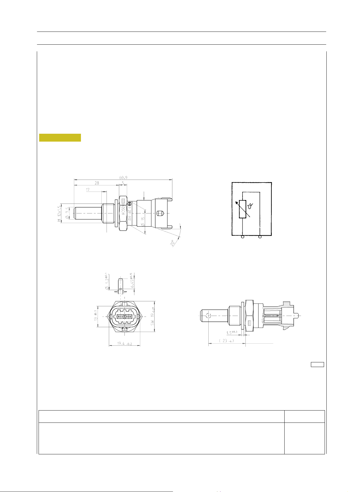
Engine coolant temperature sensor
This N.T.C. type sensor located on the water outlet sump on the engine head left measures coolant temperature for the various
operating logics with a hot or cold engine and identifies injection enrichment requirements for a cold engine or fuel reduction
requirements for a hot engine.
It is connected to electronic center pins 15/26.
Sensor behavior as a function of temperature:
-10qC8,10y 10,77 kOhm
+20qC2,28y 2,72 kOhm
+80qC0,29y 0,364 kOhm
At 60 to 90 _C, voltage at A5 and A22 ranges from 0.6 to 2.4V.
Figure 7
104266
Description Cable colour
To EDC center pin 15 (Sensor connector ”C”) K
To EDC center pin 26 (Sensor connector ”C”) Y
Print P2D32C004E Base - June 2006
Page 78
34
SECTION 3 - INDUSTRIAL APPLICATION
F2C CURSOR ENGINES
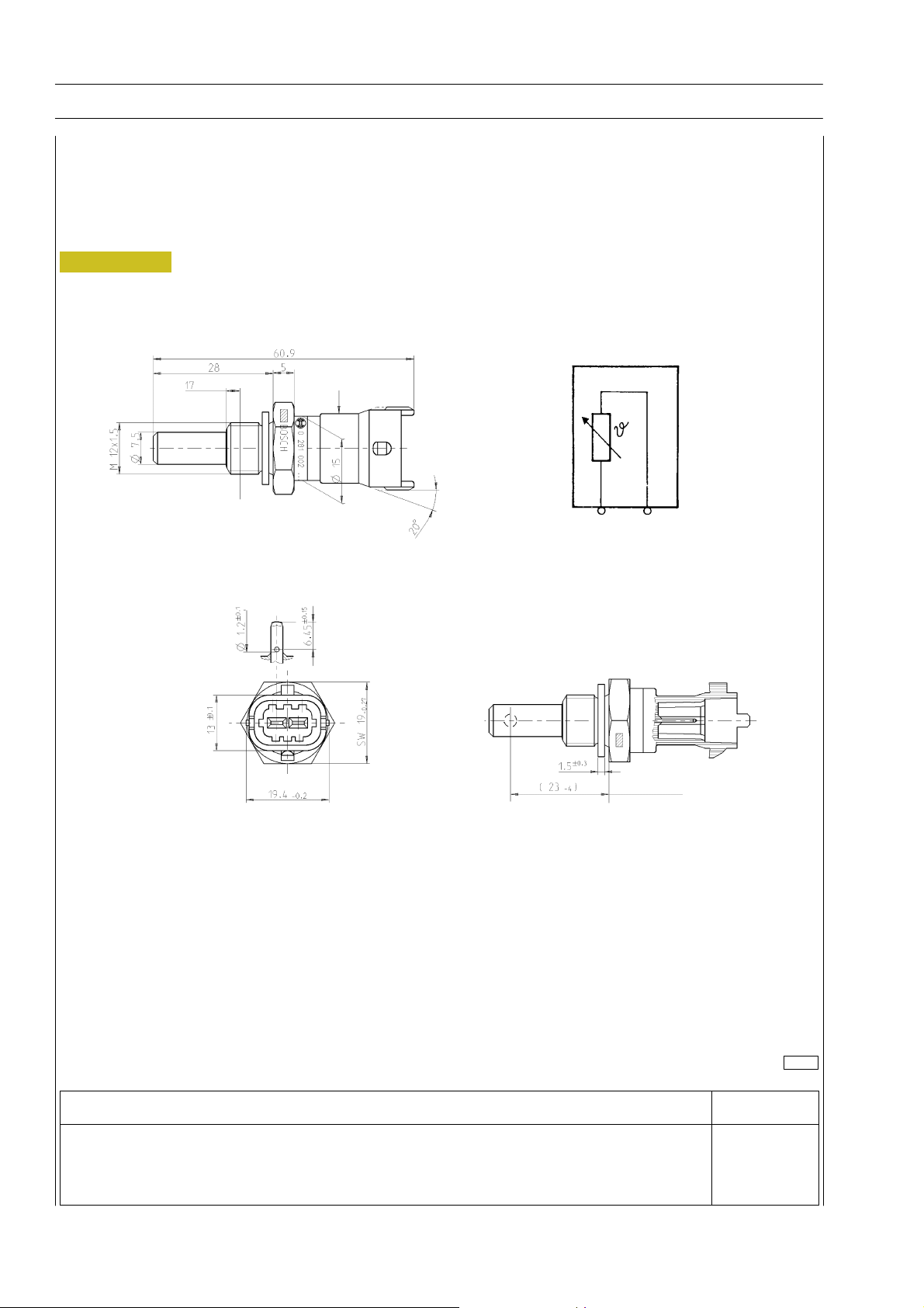
Fuel temperature sensor
Specifications
Supplier BOSCH
Max. tightening torque 35 Nm
Figure 8
104267
Description Cable colour
To pin 18 of EDC control unit (Sensor connector ”C”) O/B
To pin 35 of EDC control unit (Sensor connector ”C”) W/R
Base - June 2006 Print P2D32C004E
Page 79
F2C CURSOR ENGINES
SECTION 3 - INDUSTRIAL APPLICATION 35
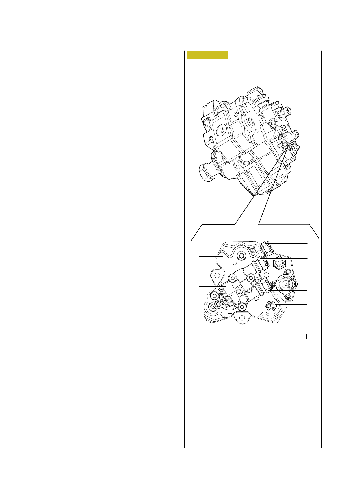
High pressure pump (pressure regulator)
Pump with 3 radial pistons commanded by timing gear,
requiring no tuning, with rotor supply pump applied on rear
end.
A. Fuel drain outlet fitting to filter support
B. Fuel inlet fitting from ECU heat exchanger
C. Fuel inlet fitting from fuel filter
D. Fuel outlet fitting from supply pump to filter
E. Fuel outlet fitting to rail
1. High-pressure pump
2. Supply pump
3. Pressure regulator (NO solenoid valve modulated by
ECU with PWM signal).
Pressure regulator
Located at high-pressure pump inlet, on low pressure system,
it modulates theamount of fuel for high-pressure pump supply
based on commands received from ECU.
It mainly consists of parts below:
- trapezoidal-section lock pin;
- valve control pin;
- pre-load valve;
- coils.
When no control signal is present, the pressure regulator is
normally open, therefore the high pressure pump is in max
delivery condition.
The ECU modul ates a PWM control signal to extend or
reduce section of fuel supply line to high-pressure pump.
The component cannot be replaced as an individual part,
therefore it cannot be removed.
The quantity of high-pressure supply fuel is metered by a
proportional valve positioned on low-pressure system and it
is managed by the ECDC 7 ECU.
The delivery pressure to rail is modulated between 250 and
1400 bars by ECU operating on pressure regulator solenoid
valve.
It is a NO solenoid valve.
Its resistance is a 3,2 :.
It is connected to ECU pins C5 - C7.
Figure 9
1
2
x
A
B
C
3
D
E
000912t
Print P2D32C004E Base - June 2006
Page 80
36
SECTION 3 - INDUSTRIAL APPLICATION
F2C CURSOR ENGINES
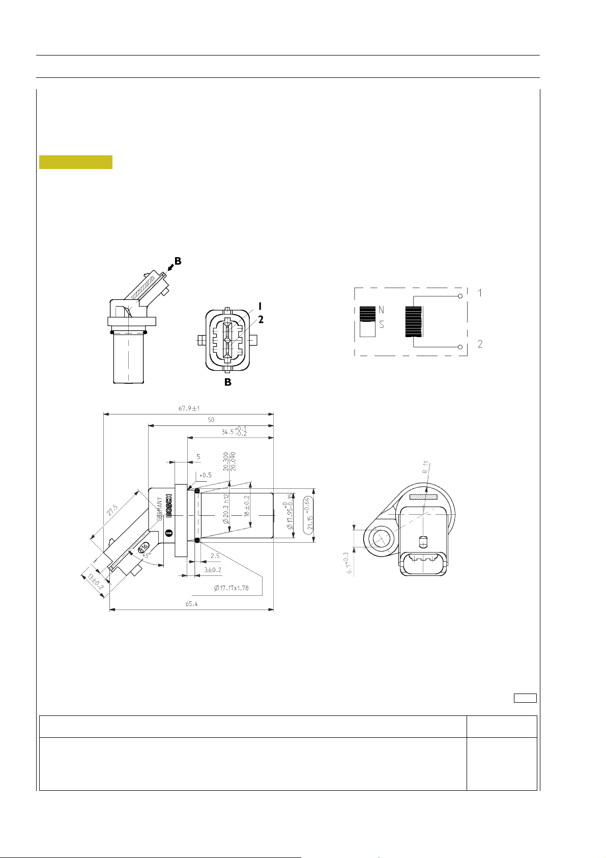
Flywheel pulse transmitter
Specifications
Supplier BOSCH
Max. tightening torque 8 r 2Nm
Figure 10
104269
Description Cable colour
To pin 19 of EDC control unit (Sensor connector ”C”) B
To pin 23 of EDC control unit (Sensor connector ”C”) W
Base - June 2006 Print P2D32C004E
Page 81
F2C CURSOR ENGINES
SECTION 3 - INDUSTRIAL APPLICATION 37
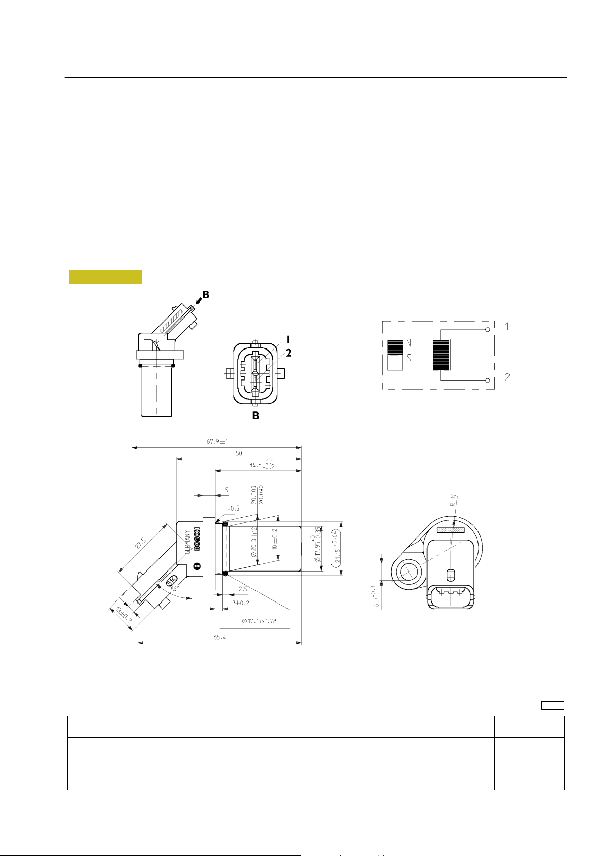
Distribution pulse transmitter
Features
Vendor BOSCH
Torque 8 r 2Nm
Resistance 880 y 920 :
This induction type sensor located on the camshaft generates signals obtained from the magnetic flow lines that close through
the 6 plus 1 phase teeth of a sound wheel mounted on the shaft.
The electronic center uses the signal generated by this sensor as an injection step signal.
This sensor’s air gap is NOT ADJUSTABLE.
Figure 11
104269
Description Cable colour
To EDC center pin 9 (Sensor connector ”C”) W
To EDC center pin 10 (Sensor connector ”C”) R
Print P2D32C004E Base - June 2006
Page 82
38
SECTION 3 - INDUSTRIAL APPLICATION
F2C CURSOR ENGINES
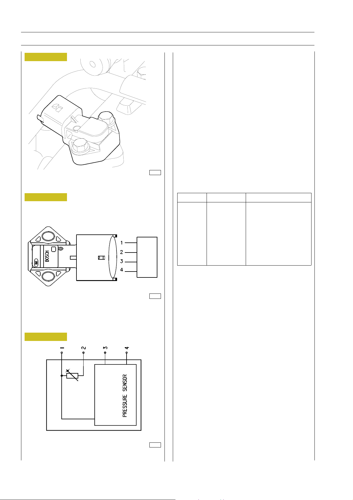
Figure 12
Figure 13
Oil temperature/pressure sensor (42030 / 47032)
This component is identical to the air pressure/temperature
sensor and replaced single sensors 47032 / 42030.
It is fitted onto the engine oil filter, in a horizontal position.
It measures the engine oil temperature and pressure.
The measured signal is sent to the EDC control unit which
controls, in turn, the indicator instrument on the dashboard
(low pressure warning lights / gauge).
Pin (EDC) 24/C - 32/C Power supply
Pin (EDC) 27/C Temperature
Pin (EDC) 28/C Pressure
The engine oil temperature is used only by the EDC control
unit.
50324
Sensor external view
Ref. Description Control unit pin
1 Ground 24C
2 Temp. Sign. 27C
Figure 14
3 +5 32C
4 Press. Sign. 28C
50323
Linking connector
50344
Wiring diagram
Base - June 2006 Print P2D32C004E
Page 83
F2C CURSOR ENGINES
SECTION 3 - INDUSTRIAL APPLICATION 39
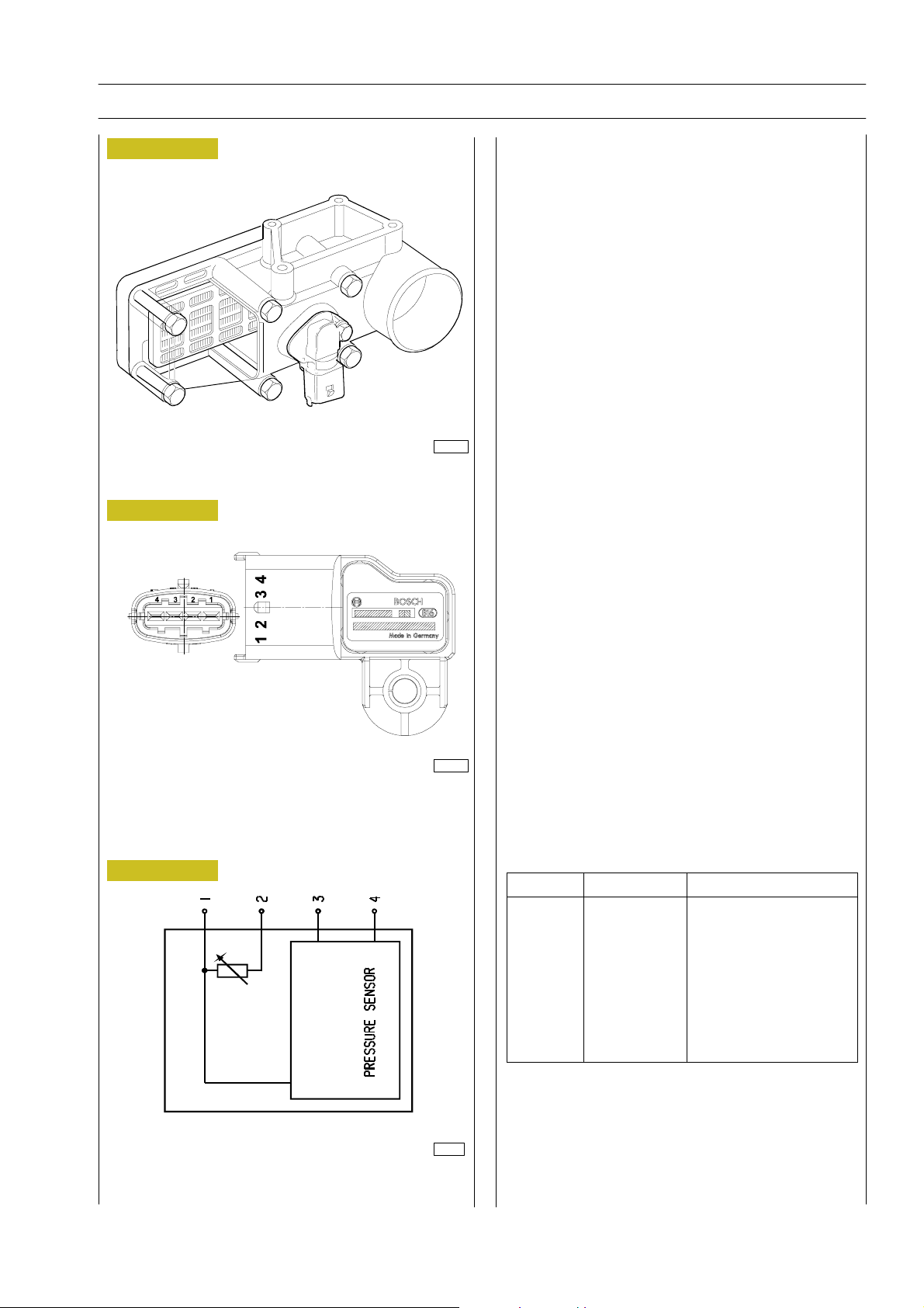
Figure 15
Figure 16
Air pressure/temperature sensor (85156).
This component incorporates a temperature sensor and a
pressure sensor.
IIt replaces the temperature sensors (85155) and pressure
sensors (85154) available in the preceding systems.
It is fitted onto the intake manifold and measures the
maximum supplied air flow rate used to accurately calculate
the amount of fuel to be injected at every cycle.
The sensor is powered with 5 V.
The output voltage is proportional to the pressure or
temperature measured by the sensor.
Pin (EDC) 25/C - 33/C Power supply
Pin (EDC) 36/C Temperature
Pin (EDC) 34/C Pressure
114266
Sensor external view
Figure 17
114273
Linking connector
Ref. Description Control unit pin
1 Ground 25C
2 Temp. Sign. 36C
3 +5 33C
4 Press. Sign. 34C
50344
Wiring diagram
Print P2D32C004E Base - June 2006
Page 84
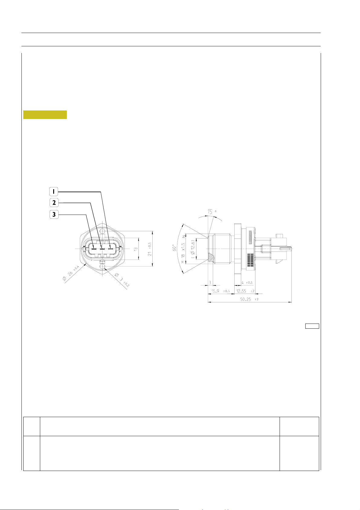
40
SECTION 3 - INDUSTRIAL APPLICATION
F2C CURSOR ENGINES
Fuel pressure sensor on rail
Installed on one rail end, it measures actual fuel pressure in order to determine injection pressure.
The injection pressure value is used for pressure check and to determine the injection electric command duration.
It is supplied with 5 volts.
It is connected to ECU on pins 12C - 13C - 14C.
Figure 18
114620
Ref. Description
Pin
ecu
1 ECU pin 12C
2 Ground 13C
3 Supply Pressure 14C
Base - June 2006 Print P2D32C004E
Page 85
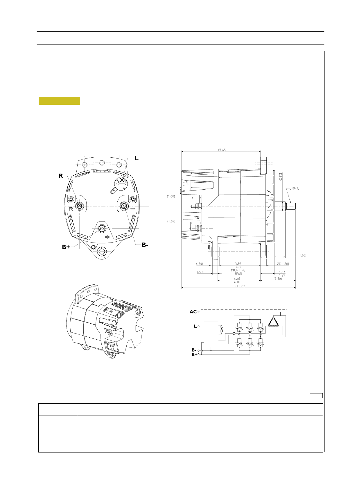
F2C CURSOR ENGINES
SECTION 3 - INDUSTRIAL APPLICATION 41
Alternator
(for types: F2CE9684A - F2CE9684B - F2CE9684C*E001 - F2CE9684D - F2CE9684L)
Supplier LEECE NEVILLE
Technical features 12V - 185A
Figure 19
104314
Connector Description
R AC Connector
L Driver warning light connector
- Negative
+ Positive
Print P2D32C004E Base - June 2006
Page 86
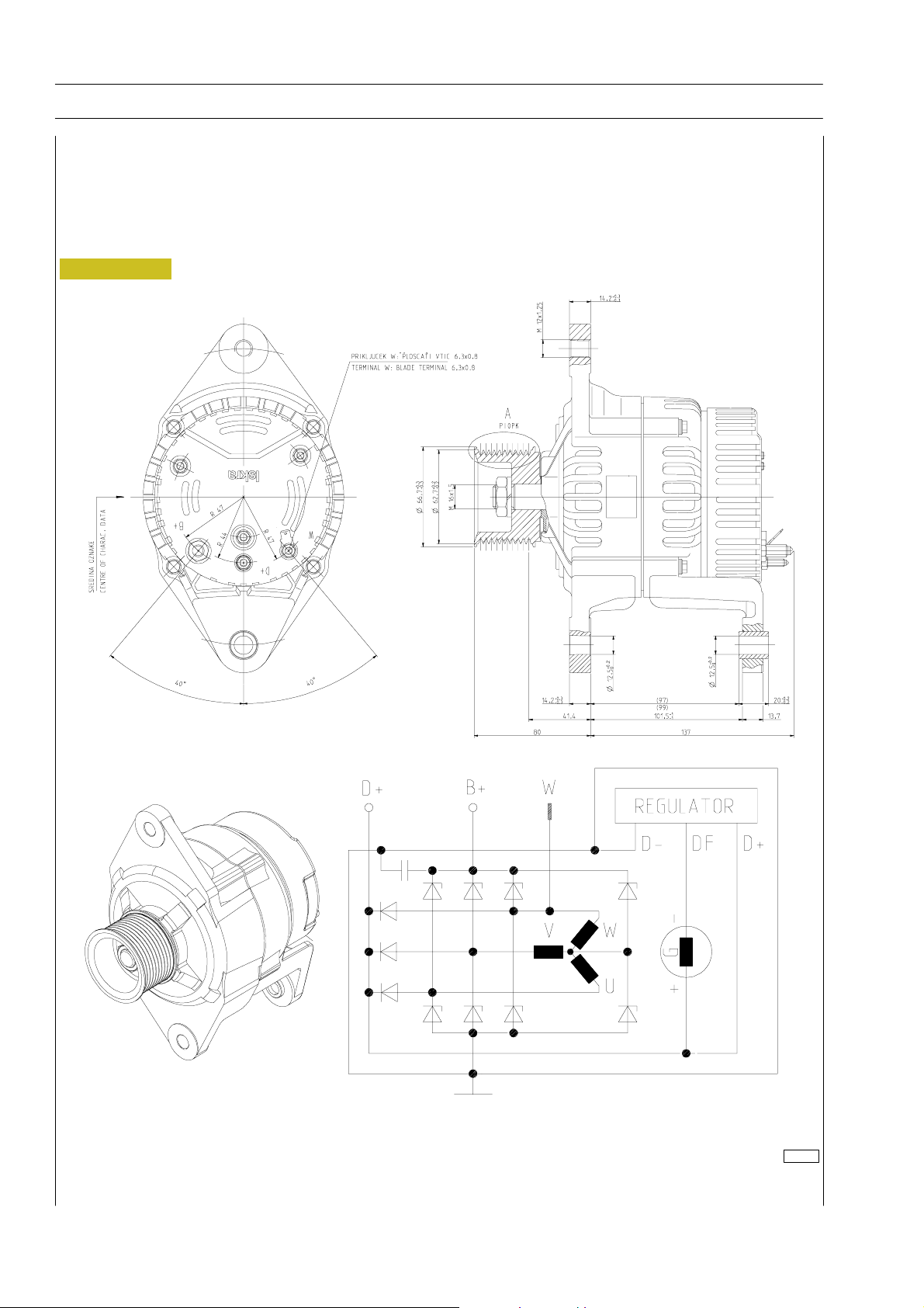
42
SECTION 3 - INDUSTRIAL APPLICATION
F2C CURSOR ENGINES
Alternator (for types: F2CE9684C*E002 - F2CE9684E)
Supplier ISKRA
Technical features 12V - 120A
Figure 20
114277
Base - June 2006 Print P2D32C004E
Page 87
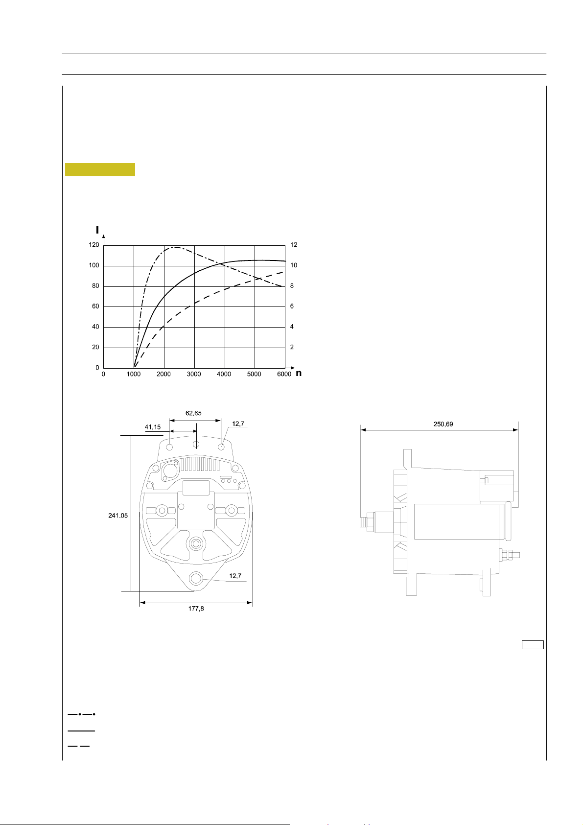
F2C CURSOR ENGINES
SECTION 3 - INDUSTRIAL APPLICATION 43
Alternator (per type: F2CE9684H)
Supplier LEECE NEVILLE
Technical features 24V - 100A
Figure 21
114295
I = outlet current
n = number of revolutions per minute
=Torque
= Outlet current
=Power
Print P2D32C004E Base - June 2006
Page 88
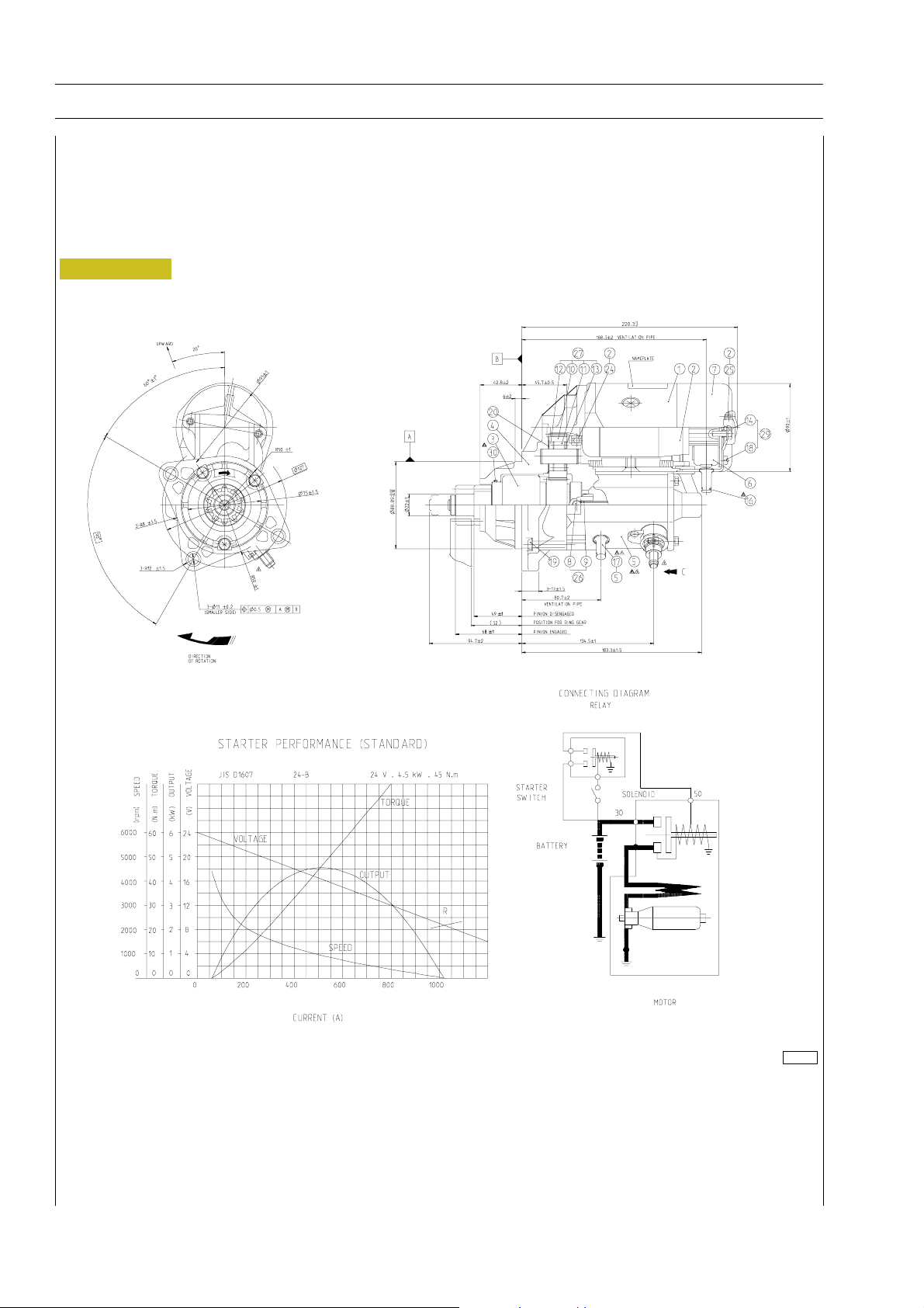
44
SECTION 3 - INDUSTRIAL APPLICATION
F2C CURSOR ENGINES
Starting motor
Specifications
Supplier DENSO
Type 2280005641
Electrical system 24 Volt
Nominal output 4.5 Kw
Figure 22
114283
Base - June 2006 Print P2D32C004E
Page 89
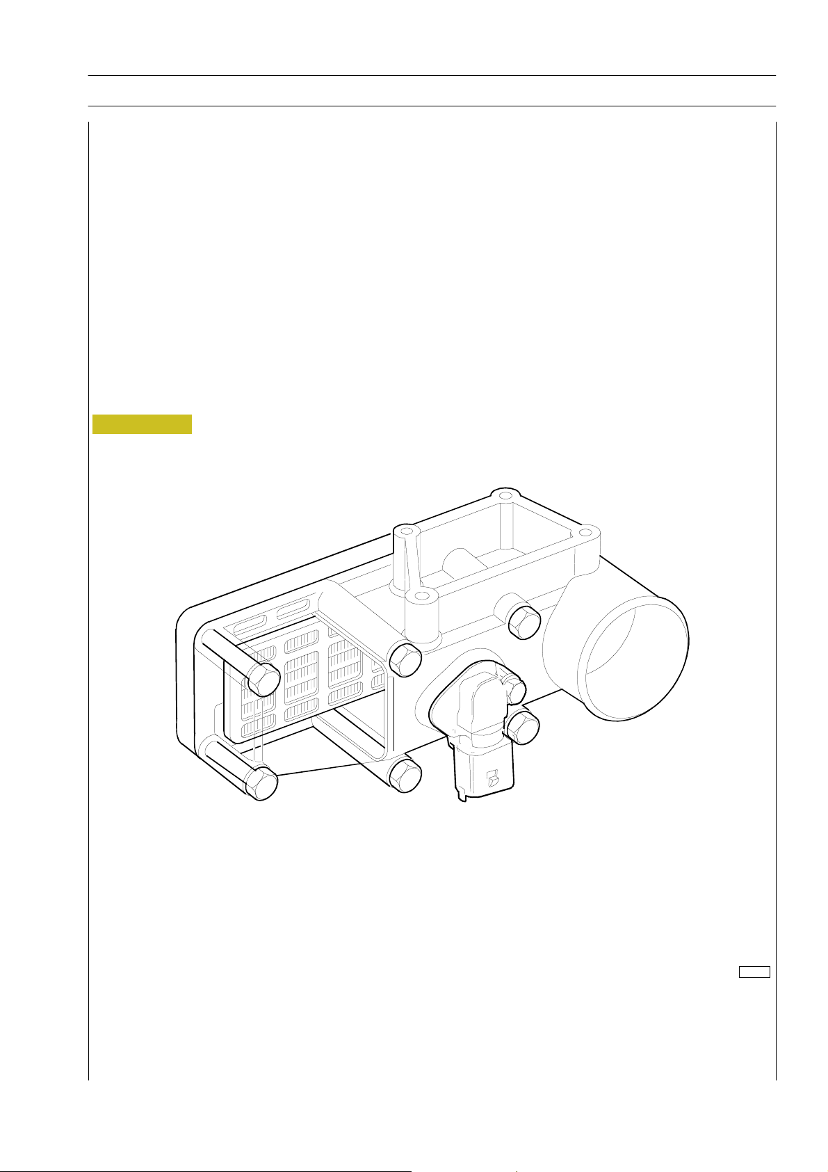
F2C CURSOR ENGINES
SECTION 3 - INDUSTRIAL APPLICATION 45
PRE/POST-HEATING RESISTANCE
The resistance is ~ 0.7 Ohm.
Such resistance is placed between the cylinder head and the suction manifold. It is used to heat up air during pre/post-heating
operations.
When the ignition key is inserted, should any one of the temperature sensors — water, air, gas oil — detect a value below 10qC,
the electronic control unit will activate pre/post-heating and turn on the relevant dashboard warning light for a variable time
depending on the temperature.
After that time, the warning light starts blinking thus informing the driver that the engine can be started.
When the engine is running the warning light goes off, while the resistance is being fed for a certain time as a result of post-heating.
If the engine is not started, with the warning light flashing, in 20 / 25 seconds, the operation is cancelled to prevent draining the
battery.
On the contrary, if reference temperatures are over 10qC, when the ignition key is inserted the warning light comes on for about
2 seconds and carries out the test and then goes out to signal that the engine can be started.
Figure 23
114610
Print P2D32C004E Base - June 2006
Page 90

46
SECTION 3 - INDUSTRIAL APPLICATION
EDC SYSTEM FUNCTIONS
The EDC 7 UC31 electronic center manages the following main functions:
Fuel injection
Accessory functions such as cruise control, speed limiter, PTO and the like
Self-diagnosis
Recovery
It also enables:
Interfacing with other electronic systems (if any) available on the vehicle
Diagnosis
Fuel dosing
Fuel dosing is calculated based on:
- accelerator position
-enginerpm
- quantity of air admitted.
The result can be corrected based on:
- water temperature
or to prevent:
-noise
-fumes
-overloads
-overheating
F2C CURSOR ENGINES
Pressure can be adjusted in case of:
- engine brake actuation
- external device actuation (e.g. speed reducer, cruise control)
- serious defects involving load reduction or engine stop.
After determining the mass of air introduced by measuring its volume and temperature, the center calculates the corresponding
mass of fuel to be injected into the cylinder involved, with account also taken of gas oil temperature.
Delivery correction based on water temperature
When cold, the engine encounters greater operating resistance, mechanical friction is high, oil is till very viscous and operating plays
are not optimized yet.
Fuel injected also tends to condense on cold metal surfaces.
Fuel dosing with a cold engine is therefore greater than when hot.
Delivery correction to prevent noise, fumes or overloads
Behaviors that could lead to the defects under review are well known, so the designer has added specific instructions to the center
to prevent them.
De-rating
In the eventof engine overheating, decreasing delivery proportionally to the temperature reached by the coolant changes injection.
Base - June 2006 Print P2D32C004E
Page 91

F2C CURSOR ENGINES
SECTION 3 - INDUSTRIAL APPLICATION 47
Injection lead electronic control
Injection lead, or the start of fuel delivery expressed in degrees, can differ from one injection to the next, even from one cylinder
to another and is calculated similarly to delivery according to engineload, namely, accelerator position, engine rpmand air admitted.
Lead is corrected as required:
- during acceleration
- according to water temperature
and to obtain:
- reduced emissions, noise abatement and no overload
- better vehicle acceleration
High injection lead is set at start, based on water temperature.
Delivery start feedback is given by injection electro valve impedance variation.
Engine start
Cylinder 1 step and recognition signal synchronization (flywheel and drive shaft sensors) takes place at first engine turns. Accelerator
pedal signal is ignored at start. Star delivery is set exclusively based on water temperature, via a specific map. The center enables
the accelerator pedal, when it detects flywheel acceleration and rpm such as to consider the engine as started and no longer drawn
by the starter motor.
Cold start
Pre-post reheating is activated when even only one of the three water, air or gas oil temperature sensors records a temperature
of below 10 _C. The pre-heat warning light goes on when the ignition key is inserted and stays on for a variable period of time
according to temperature, while the intake duct input resistor heats the air, then starts blinking, at which point the engine can be
started.
The warning light switches off with the engine revving, while the resistor continues being fed for a variable period of time to
complete post-heating. The operation is cancelled to avoid uselessly discharging the batteries if the engine is not started within 20
y 25 seconds with the warning light blinking. The pre-heat curve is also variable based on battery voltage.
Hot start
On inserting the ignition key the warning light goes on for some 2 seconds for a short test and then switches off when all reference
temperatures are above 10 _C. The engine can be started at this point.
Run Up
When the ignition key is inserted, the center transfers data stored at previous engine stop to the main memory (Cf. After run),
and diagnoses the system.
After Run
At each engine stop with the ignition key, the center still remains fed by the main relay for a few seconds, to enable the
microprocessor to transfer some data from the main volatile memory to an non-volatile, cancelable and rewritable (Eeprom)
memory to make tem available for the next start (Cf. Run Up).
These data essentially consists of:
- miscellaneous settings, such as engine idling and the like
- settings of some components
- breakdown memory
The process lasts for some seconds, typically from 2 to 7 according to the amount of data to be stored, after which the ECU sends
a command to the main relay and makes it disconnect from the battery.
Print P2D32C004E Base - June 2006
Page 92

48
SECTION 3 - INDUSTRIAL APPLICATION
F2C CURSOR ENGINES
This procedure must never be interrupted, by cutting the engine off from the battery cutout or disconnecting the latter before
10 seconds at least after engine cutout.
In this case, system operation is guaranteed until the fifth improper engine cutout, after which an error is stored in the breakdown
memory and the engine operates at lower performance at next start while the EDC warning light stays on.
Repeated procedure interruptions could in fact lead to center damage.
Cut-off
It refers to the supply cut-off function during deceleration.
Cylinder Balancing
Individual cylinder balancing contributes to increasing comfort and operability.
This function enables individual personalized fuel delivery control and deliverystart for each cylinder, even differently between each
cylinder, to compensate for injector hydraulic tolerances.
The flow (rating feature) differences between the various injectors cannotbe evaluateddirectly by the control unit. Thisinformation
is provided by the entry of the codes for every single injector, by means of the diagnosis instrument.
Not present on agricultural versions.NOTE
Synchronization search
The center can anyhow recognize the cylinder to inject fuel into even in the absence of a signal from the camshaft sensor.
If this occurs when the engine is already started, combustion sequence is already acquired, so the center continues with the
sequence it is already synchronized on; if it occurs with the engine stopped, the center only actuates one electro valve. Injection
occurs onside that cylinder within 2 shaft revs at the utmost so the center is only required to synchronize on the firing sequence
and start the engine.
Base - June 2006 Print P2D32C004E
Page 93

F2C CURSOR ENGINES
SECTION 3 - INDUSTRIAL APPLICATION 49
PART THREE - TROUBLESHOOTING
Print P2D32C004E Base - June 2006
Page 94

50
SECTION 3 - INDUSTRIAL APPLICATION
F2C CURSOR ENGINES
Base - June 2006 Print P2D32C004E
Page 95

F2C CURSOR ENGINES
SECTION 3 - INDUSTRIAL APPLICATION 51
PREFACE
A successful troubleshooting is carried out with the
competence acquired by years of experience and attending
training courses.
When the user complains for bad efficiency or working
anomaly, his indications must be kept into proper
consideration using them to acquire any useful information to
focus the intervention.
After the detection of the existing anomaly, it is
recommended to proceed with the operations of
troubleshooting by decoding the auto-troubleshooting data
provided by the EDC system electronic central unit.
The continuous efficiency testsof the components connected
to, and the check of working conditions of the entire system
carried out during working, can offer an important diagnosis
indication, available through the decoding of the
”failure/anomaly” codes issued by blinking of the failure led:
the ”blink-code” (whether programmed).
Please consider that the interpretation of the indications
provided by the blink-code is not sufficient to guarantee the
solution to the existing anomalies.
Using Iveco Motors processing instruments, it is also possible
to establish a bi-directional connection with the central unit,
by which not only to decoding the failure codes but also input
an enquiry relying on memory files, in order to achieve any
further necessary information to identify the origin of the
anomaly.
Every time there is a breakdown claim and this breakdown is
actually detected, it is necessary to proceed inquiring the
electronic unit in one of the ways indicated and then proceed
with the diagnostic research making trials and tests in order to
have a picture of the working conditions and identify the root
causes of the anomaly.
In case the electronic device is not providing any indication, it
will be necessary to proceed relying on the experience,
adopting traditional diagnosis procedures.
In order to compensate the operators’ lack of experience in
this new system, we are hereby providing the USER’s
GUIDELINE FOR TROUBLESHOOTING in the following
pages.
Any kind of operation on the electronic center unit
must be executed by qualified personnel, duly
!
authorized by Iveco Motors.
Any unauthorized tamper will involve decay of
after-sales service in warranty.
Print P2D32C004E Base - June 2006
Page 96

52
SECTION 3 - INDUSTRIAL APPLICATION
F2C CURSOR ENGINES
FAULT CODES
Failure code Failure description Warning lamp
Vehicle 1 (Sensors/Plausibility checks)
10019 Terminal 15 failure
Vehicle 2 (Lamps/relays/actuators)
10025 Main relay defect
20025 Interrupted afterrun
10026 Battery voltage fault SysLamp ON
10028 Main relay SCBatt (Lambda H./Grid H./Batt.switch) SysLamp ON
20028 Main relay SCGND
10029 Main relay 3
1002B Power stage air heater 1 actuator SysLamp ON
1002E Grid heater always switched on
Engine 1 (Temperature and Pressure Sensors)
10031 Coolant temperature sensor SysLamp ON
10032 Coolant temperature sensor dynamic test
10033 Boost Temp. Signal
10034 Boost pressure sensor SysLamp ON
10035 Fuel Temp. Signal SysLamp ON
10036 Rail pressure sensor CP3 SysLamp ON
20036 Rail pressure sensor offset monitoring SysLamp ON
10037 Rail pressure relief valve SysLamp ON
10038 Oil Pressure Sensor SysLamp ON
20038 Oil Pressure too low SysLamp ON
20032 Coolant temperature sensor SysLamp ON
1003A Oil Temp. Sensor SysLamp ON
2003A Oil Temperature above normal SysLamp ON
Engine 2 (Speed sensing/actuators)
10041 Crankshaft sensor failure SysLamp ON
10042 Running with camshaft sensor only SysLamp ON
10043 Camshaft sensor failure SysLamp ON
10044 Offset between camshaft and cranksh SysLamp ON
1004D Engine overspeed protection
Fuel metering CR Systems
Fuel metering Unit Injector Systems
10052 Rail pr.max.pos.deviation exceeded conc.set flow of fuel SysLamp ON
10053 Max. negative rail pressure deviation with metering unit on lower limit is exceeded SysLamp ON
10054 Minimum rail pressure exceeded SysLamp flashes
10055 Maximum rail pressure exceeded SysLamp flashes
10056 Rail pressure drop rate is higher than expected SysLamp ON
10057 Setpoint of metering unit in overrun mode not plausible
10058 Setpoint of fuel volume flow through metering unit is lower than calculated limit SysLamp ON
10059 Metering unit PWM-powerstage SysLamp ON
20059 Short circuit to battery of metering unit output SysLamp ON
30059 Short circuit to ground of metering unit output
1005B High pressure test (deactivates rail pr.Monitor)
Base - June 2006 Print P2D32C004E
Page 97

F2C CURSOR ENGINES
SECTION 3 - INDUSTRIAL APPLICATION 53
Failure code Failure description Warning lamp
Injectors 1
10061 Cylinder1 - Short circuit Low/High SysLamp ON
10062 Cylinder2 - Short circuit Low/High SysLamp ON
10063 Cylinder3 - Short circuit Low/High SysLamp ON
10064 Cylinder4 - Short circuit Low/High SysLamp ON
10065 Cylinder5 - Short circuit Low/High SysLamp ON
10066 Cylinder6 - Short circuit Low/High SysLamp ON
10067 Cylinder1 - Open load SysLamp ON
10068 Cylinder2 - Open load SysLamp ON
10069 Cylinder3 - Open load SysLamp ON
1006A Cylinder4 - Open load SysLamp ON
1006B Cylinder5 - Open load SysLamp ON
1006C Cylinder6 - Open load SysLamp ON
1006E The minimum number of injections was not reached --> stop the engine
Injectors 2
10071 Bank 1 specific errors - Short circuit / not classifyable SysLamp ON
10073 Bank 2 specific errors - Short circuit / not classifyable SysLamp ON
1007C Chip-specific errors-->only lamp on SysLamp ON
2007C Chip-specific errors-->only lamp on SysLamp ON
Boost system and turbine speed
1009D Torque limitation due to limited performance
1009E Torque limitation due to excessive smoke
4009E Torque limitation due to mechanical part protection
6009E Torque limitation due to fuel quantity reduction
Interfaces 1 (CAN-Bus)
100B1 Busoff in CAN A
100B3 Busoff in CAN C
200B4 Timeout for BC2EDC2 SysLamp ON
100B5 Timeout for VM2EDC SysLamp ON
Interfaces 2 (CAN messages timeout)
100C6 Timeout of CAN message TSC1-PE SysLamp ON
200C6 Timeout of CAN message TSC1-TE (inactive) SysLamp ON
100C8 Timeout of CAN message TSC1-VE SysLamp ON
300C8 Timeout of CAN message TSC1-VR (inactive) SysLamp ON
ECU 1 (internal checks)
100D1 Communication error of SPI SysLamp flashes
100D2 Error state of EEPROM
100D3 Recovery which is locked SysLamp flashes
200D3 Recovery which is suppressed SysLamp flashes
300D3 Recovery which is visible SysLamp flashes
100D4 Communic.supervision Watchdog/Contr.-Flag SysLamp flashes
100D5 Redundant shutoff paths during initial. SysLamp flashes
100D6 Deviation between TPU and system time SysLamp ON
100D7 Dataset variant coding SysLamp flashes
100D8 Supervision of SPI-handler Flag SysLamp ON
100D9 Error status ADC monitoring SysLamp ON
Print P2D32C004E Base - June 2006
Page 98

54
SECTION 3 - INDUSTRIAL APPLICATION
F2C CURSOR ENGINES
Failure code Failure description Warning lamp
ECU 2 (Powerst./Immobil./Overrun/Sensor supply)
100E1 Short circuit to Batt or Ground, no load, excess.temp. for high side power stage SysLamp ON
200E1 Short circuit to Batt or Ground, no load, excess.temp. for low side power stage SysLamp ON
100E3 Energising time exceeds limit of overrun monitor. SysLamp flashes
100E4 Plausibility error in engine speed check SysLamp flashes
100E5 12V sensor supply voltage SysLamp flashes
100E6 Sensor supply voltage 1 SysLamp ON
100E7 Sensor supply voltage 2 SysLamp ON
100E8 Sensor supply voltage 3 SysLamp ON
100E9 Supply voltage ECU upper limit SysLamp flashes
100EA Supply voltage ECU lower limit SysLamp flashes
100EB Atmospheric pressure sensor SysLamp ON
Base - June 2006 Print P2D32C004E
Page 99

F2C CURSOR ENGINES
SECTION 3 - INDUSTRIAL APPLICATION 55
PART FOUR -
MAINTENANCE PLANNING
Print P2D32C004E Base - June 2006
Page 100

56
SECTION 3 - INDUSTRIAL APPLICATION
F2C CURSOR ENGINES
Base - June 2006 Print P2D32C004E
 Loading...