


 Loading...
STRALIS
EURO 6
BODYBUILDERS INSTRUCTIONS
<![if ! IE]><![endif]> H E A V Y R A N G E
ISSUE 2013
IVECO S.p.A
Technical Application & Homologation Strada delle Cascinette, 424/34 10156 Torino (TO) - Italy
www.iveco.com
Printed 603.95.513 – 1st ed. 06/2013
Images and text: IVECO S.p.A. 2013 All rights reserved.

STRALIS Euro 6 ‒ GUIDELINES FOR TRANSFORMATION AND
GUIDELINES FOR TRANSFORMATION AND VERSIONS 5 UPDATE DATA
GUIDELINES FOR TRANSFORMATION AND VERSIONS
UPDATE DATA
Section |
Description |
Page |
Revision date |
|
|
|
|
|
|
|
|
|
|
|
– Printed 603.95.513 – Base 06/2013

- Printed 603.95.513 – Base 06/2013
STRALIS Euro 6 ‒ GUIDELINES FOR TRANSFORMATION AND
6GUIDELINES FOR TRANSFORMATION AND VERSIONS INTRODUCTION
INTRODUCTION
This publication provides information, features and instructions for transformation and fitting of the vehicle; considering the type of content, it is meant for qualities and specialised staff.
The Bodybuilder is manager of the project and its execution, and must assure compliance with what is set forth in this publication and in the laws in forth.
Any modification, transformation or fitting not provided by this manual and not expressly authorised, will result in exemption of any liability by IVECO and in particular, if the vehicle is covered by a guarantee, the immediate dissolution of the same.
This criterion also applies with regard to single units and components, those described in this manual have been submitted by IVECO to for deliberations, approvals and inspections and belong to normal production. The use of any type of unit not recognised (such as PTO, tyres, horns, etc.) relieves IVECO from any liability.
IVECO is available to provide information on the implementation of the interventions and to provide instructions for any cases and situations not covered in this publication.
Before performing any operation, it is necessary to:
●verify that you have the manuals for the vehicle model on which you are about to work;
●ensure that all the safety devices (goggles, helmet, gloves, shoes, etc.), as well as the equipment used for work, lifting and transport, is available and working;
●ensure that the vehicle is placed in safe conditions.
At the end of the operation, the operational, efficiency and safety conditions set by IVECO must be restored. Contact the Service network for vehicle calibration if necessary.
Data and information contained in this publication may be outdated as a result of changes adopted by IVECO, at any time, for technical or commercial reasons or due to the need to adapt the vehicle to new legal requirements.
In the event of discordance between the information herein and the actual vehicle, please contact the Product Manager operating on the market before performing any interventions.
SYMBOLS - WARNINGS
Danger for persons
Failure to comply with these prescriptions can result in the risk of serious injury.
Risk of serious damage to the vehicle
Partial or complete non observance of these prescriptions can lead to serious damages to the vehicle and can sometimes result in the guarantee being voided.
General danger
Includes the dangers of both above described signals.
Environmental protection
Indicates correct behaviour in order that vehicle use is as environmentally friendly as possible.
NOTE Indicates an additional explanation for a piece of information.
– Printed 603.95.513 – Base 06/2013

- Printed 603.95.513 – Base 06/2013

INDEX OF SECTIONS
GENERAL INFORMATION |
1 |
CHASSIS INTERVENTIONS |
2 |
APPLICATIONS OF |
|
SUPERSTRUCTURES |
3 |
POWER TAKE-OFFS |
4 |
ELECTRONIC |
|
SUB-SYSTEMS |
5 |
SPECIAL INSTRUCTIONS |
|
FOR SCR EXHAUST SYSTEM |
6 |
- Printed 603.95.513 – Base 06/2013

- Printed 603.95.513 – Base 06/2013

SECTION 1
GENERAL
INFORMATION
- Printed 603.95.513 – Base 06/2013

- Printed 603.95.513 – Base 06/2013
STRALIS Euro 6 ‒ GENERAL INFORMATION |
|
||
3 |
|||
|
GENERAL INFORMATION |
||
|
Index |
|
|
|
|
|
|
Index |
|
|
|
1.1 SCOPE OF THE GUIDELINES . . . . . . . . . . . . . |
5 |
|
|
1.2 TECHNICAL DOCUMENTATION AVAILABLE |
|
|
|
ELECTRONICALLY . . . . . . . . . . . . . . . . . . . . . . . |
5 |
|
|
1.3 IVECO AUTHORISATION . . . . . . . . . . . . . . . |
5 |
|
|
1.4 AUTHORISATION REQUEST . . . . . . . . . . . . . |
6 |
|
|
1.5 RESPONSIBILITIES . . . . . . . . . . . . . . . . . . . . |
6 |
|
|
1.6 LEGISLATIVE REQUIREMENTS . . . . . . . . . . . . |
6 |
|
|
1.7 MULTI-STAGE APPROVAL - COLLABORATION |
|
|
|
(only for EU countries, Switzerland and Turkey) . . . . . |
6 |
|
|
1.8 GUARANTEES . . . . . . . . . . . . . . . . . . . . . . |
7 |
|
|
1.9 QUALITY SYSTEM MANAGEMENT . . . . . . . . . . |
8 |
|
|
1.10 ACCIDENT PREVENTION . . . . . . . . . . . . . . |
8 |
|
|
1.11 CHOICE OF MATERIALS TO USE: ECOLOGY |
|
|
|
- RECYCLING . . . . . . . . . . . . . . . . . . . . . . . . . . |
8 |
|
|
1.12 VEHICLE MANAGEMENT ON THE PART OF |
|
|
|
BODYBUILDER . . . . . . . . . . . . . . . . . . . . . . . . . |
9 |
|
|
Acceptance of chassis . . . . . . . . . . . . . . . . . . . . |
9 |
|
|
Maintenance . . . . . . . . . . . . . . . . . . . . . . . . . |
9 |
|
|
Delivery of the vehicle to the final customer . . . . . |
9 |
|
|
1.13 VEHICLE NAMES . . . . . . . . . . . . . . . . . . . |
10 |
|
|
Commercial name . . . . . . . . . . . . . . . . . . . . . |
10 |
|
|
1.14 TRADEMARKS AND SYMBOLS . . . . . . . . . . |
11 |
|
|
1.15 DIMENSIONS AND GROUND . . . . . . . . . . |
11 |
|
|
General information . . . . . . . . . . . . . . . . . . . . |
11 |
|
|
Determination of the centre of gravity of the |
|
|
|
superstructure and the payload . . . . . . . . . . . . . |
11 |
|
|
Respect of the permitted masses . . . . . . . . . . . . |
15 |
|
|
1.16 INSTRUCTIONS FOR PROPER |
|
|
|
FUNCTIONING OF THE VEHICLE PARTS AND |
|
|
|
ACCESSIBILITY . . . . . . . . . . . . . . . . . . . . . . . . |
16 |
|
|
1.17 CONVENTIONS . . . . . . . . . . . . . . . . . . . |
17 |
|
|
– Printed 603.95.513 – Base 06/2013

STRALIS Euro 6 ‒ GENERAL INFORMATION
4 GENERAL INFORMATION
– Printed 603.95.513 – Base 06/2013

STRALIS Euro 6 ‒ GENERAL INFORMATION
GENERAL INFORMATION |
5 |
1.1 SCOPE OF THE GUIDELINES
GENERAL INFORMATION 1.1 SCOPE OF THE GUIDELINES
The scope of this publication is to provide information, features and instructions for fitting and transformation of the original IVECO vehicle in order to ensure its functionality, safety and reliability.
These Guidelines also aim to indicate to Bodybuilders:
●the quality level to be obtained;
●obligations regarding the safety of operations;
●obligations regarding the objective responsibility of the product.
It should be noted that the collaboration with IVECO is based on the assumption that the Bodybuilder uses the maximum of their technical and organisational skills and that operations are technically and perfectly complete. As outlined below, the topic is extensive and we can only provide the rules and minimum precautions that can allow development of the technical initiative.
Faults or defects caused by total or partial failure to comply with these Guidelines are not covered by the guarantee on the chassis or relative mechanical units.
1.2 TECHNICAL DOCUMENTATION AVAILABLE ELECTRONICALLY
On the website www.ibb.iveco.com the following technical documentation is available:
●Guidelines for transformation and fitting of vehicles;
●technical specifications;
●truck diagrams;
●tractor diagrams;
●chassis diagrams;
●other range-specific data.
Requests to access the site must be made exclusively at www.ibb.iveco.com.
1.3 IVECO AUTHORISATION
Modifications or fittings proved in these Guidelines and carried out in respect of the same do not require a specific authorisation. On the other hand, IVECO authorisation is required to carry out:
●particular changes to the wheelbase;
●work on the braking system;
●modifications to the steering system:
●modifications to the stabiliser bars and suspensions;
●modifications to the cab, cab mounts, locking and tilting devices;
●modifications to intake, engine exhaust and SCR components;
●applications of retarders;
●power take-off applications;
●variations in tyre measurements;
●modifications to hook organisms (hooks, fifth wheels).
– Printed 603.95.513 – Base 06/2013

STRALIS Euro 6 ‒ GENERAL INFORMATION
6GENERAL INFORMATION 1.4 AUTHORISATION REQUEST
1.4 AUTHORISATION REQUEST
Authorisation requests, when necessary, must be sent to the responsible IVECO Departments on the market.
The Bodybuilder must provide vehicle data (cab, wheelbase, overhang, chassis No.) and adequate documentation (drawings, calculations, technical report, etc.) showing the realisation, use and operating conditions of the vehicle. The drawings should evidence everything that differs from these instructions.
The Bodybuilder will be responsible for obtaining final approval from the competent authority for completed operations.
1.5 RESPONSIBILITIES
The authorisations issued by IVECO are exclusively related to the technical/conceptual feasibility of the modification and/or fitting. The Bodybuilder is therefore responsible for:
●the design;
●the choice of materials;
●the implementation;
●the compliance of the design and implementation to any specific indications provided by IVECO and the laws in force in the countries where the vehicle is destined;
●effects on functionality, safety, reliability and, in general, good behaviour of the vehicle;
●the supply of spare parts for a minimum period of 10 years starting from the last fitting of an order and for all pieces and components that are installed.
1.6 LEGISLATIVE REQUIREMENTS
The Bodybuilder must verify that the final product is compliant, without exception, to all applicable legal requirements, on the municipal/autonomous/national level of each State in which it is registered and/or will circulate (Highway code, Official Regulations, etc.) and on the international level (European Union Directives, ONU/Geneva ECE Regulations, etc.). It is also necessary to comply with all requirements for accident prevention, instructions for assistance, the environment, etc.
The regulations on accident prevention or the legal indications cited in these Guidelines may be considered the most important, but are not meant in any way to replace or eliminate the obligation and responsibility of the Bodybuilder to stay properly informed.
For this reason, IVECO shall not be held liable for any consequences due to errors caused by insufficient knowledge or incorrect interpretation of the legal provisions in force.
1.7 MULTI-STAGE APPROVAL - COLLABORATION (only for EU countries, Switzerland and
Turkey)
Attachment XVII of Directive 2007/46/EC concerns Multi-stage approval.
This procedure requires that each manufacturer is responsible for the approval and compliance of the production of systems, components and "separate technical units" produced by the same or applied to the vehicle.
The manufacturer of the vehicle is defined as first-stage manufacturer, while the bodybuilder is defined as Second-stage manufacturer or that of the next stage.
– Printed 603.95.513 – Base 06/2013

STRALIS Euro 6 ‒ GENERAL INFORMATION
GENERAL INFORMATION |
7 |
1.8 GUARANTEES |
|
|
|
191319 |
|
Figure 1 |
1. |
IVECO |
3. |
Bodybuilder |
2. |
Dealer |
4. |
Customer |
Based on this Directive, IVECO (main vehicle manufacturer) and a Bodybuilder intending to launch the multi-stage approval process must sign a specific Collaboration Contract, called Technical Agreement, which sets out the content and reciprocal obligations in detail.
Consequently:
1.IVECO has the responsibility of providing, in the agreed form, the approval documents (EC/ECE approvals) and the technical information necessary for the proper implementation of the fitting and/or transformation (manuals, drawings, specifications);
2.the Bodybuilder has the following responsibilities:
■the design and implementation of modifications to the basic vehicle received from IVECO,
■reattainment of approvals of systems already approved in a previous stage when, due to changes on the basic vehicle the approvals need to be updated,
■compliance with national/international laws and in particular the laws of the destination country, for all changes made,
■presentation of the changes made to a technical service, for evaluation,
■appropriate documentation of the changes made, in order to give objective evidence of compliance to the aforementioned provisions of law (e.g. approval documents/test reports).
Before signing the Technical Agreement IVECO reserves the right to visit the Bodybuilder, in order to verify qualifications to carry out the fittings and/or processing for which the above collaboration is requested.
The contents of the Technical Agreement can be evaluated in detail upon request to the Manager for relations with the Bodybuilder for the single Market.
1.8 GUARANTEES
The guarantee that the work has been performed to standard must be given by the Bodybuilder who made the superstructure or modifications to the chassis, in full compliance with the instructions in these Guidelines.
IVECO reserves the right to void the guarantee on the vehicle, if:
●unauthorised fittings or transformations have been carried out;
●a chassis not suitable for the fitting or intended use has been used;
●the standards, specifications and instructions, provided by IVECO for proper execution of the work, have not been respected;
●original spare parts or components made available by IVECO for specific operations have not been used;
●safety regulations have not been respected;
●the vehicle is used for purposes other than those for which it was designed.
– Printed 603.95.513 – Base 06/2013
STRALIS Euro 6 ‒ GENERAL INFORMATION
8GENERAL INFORMATION
1.9 QUALITY SYSTEM MANAGEMENT
1.9 QUALITY SYSTEM MANAGEMENT
IVECO has always promoted the training and development of a Quality System for Bodybuilders.
This requirement is not only due to regulations on product liability, but also to the increasingly higher quality level demands, new organizational forms in various sectors and the search for more advanced levels of efficiency.
IVECO therefore considers it appropriate for Bodybuilders to be equipped with:
●organizational charts for roles and responsibilities;
●quality objectives and indicators;
●design technical documentation;
●process documentation, including controls;
●plan for product improvement, also obtained through corrective actions;
●post-sales assistance;
●training and qualification of staff.
The availability of ISO 9001 certification, even though not required, is considered very important by IVECO.
1.10 ACCIDENT PREVENTION
Do not allow unauthorised staff to intervene or operate on the vehicle.
It is forbidden to use the vehicle with safety devices that have been tampered with or are damaged.
Structures and devices installed on the vehicle must comply with the applicable regulations for accident prevention, and with safety regulations required in the individual countries where the vehicles will be used.
All precautions dictated by technical knowledge must be taken to avoid damage and functional defects. Compliance with these requirements must be overseen by the builders of the structures and devices.
Seats, coatings, gaskets, protective panels, etc., may pose a fire hazard when exposed to an in-
tense heat source. Remove them before working with welding and with flames.
1.11 CHOICE OF MATERIALS TO USE: ECOLOGY - RECYCLING
In the study and design phase, the choice of materials to be used by be made carefully, even from the ecological and recycling point of view.
To this regard, please note that:
●it is forbidden to use materials that are harmful to health, or at least which may pose a risk, such as those containing asbestos, lead, halogen additives, fluorocarbons, cadmium, mercury, hexavalent chromium, etc.;
●it is advisable to use materials whose processing produces limited waste quantities and allows easy recycling after first use;
●in synthetic materials of the composite type, it is advisable to use components that are compatible with each other, allowing use with the possible addition of other recovery components. Prepare the required markings in accordance with the regulations in force;
●the batteries contain substances that are very dangerous for the environment. To replace the batteries it is possible to go to the Service Network, equipped for disposal in accordance with the nature and the law.
To comply with Directive 2000/53 EC (ELVs), IVECO prohibits the in-vehicle installation of components that contain lead, mercury, cadmium and hexavalent chromium; exceptions are made in cases allowed by Annex II of the above Directive.
– Printed 603.95.513 – Base 06/2013

STRALIS Euro 6 ‒ GENERAL INFORMATION
GENERAL INFORMATION 9 1.12 VEHICLE MANAGEMENT ON THE PART OF BODYBUILDER
1.12 VEHICLE MANAGEMENT ON THE PART OF BODYBUILDER
Acceptance of chassis
The Bodybuilder receiving a chassis/vehicle from IVECO or from a Dealer must perform a preliminary check, notifying of any missing accessories or damage attributable to the transporter.
Maintenance
To preserve the chassis/vehicle in its full efficiency, even while parking in the warehouse, maintenance operations may be necessary within a predetermined time.
The expenses for carrying out these operations are borne by the owner of the vehicle in that moment (Bodybuilder, Dealer or Customer).
In case of long periods of vehicle inactivity, it is advisable to disconnect the negative pole of the
battery to maintain optimal charging status.
Delivery of the vehicle to the final customer
Before delivering the vehicle, the Bodybuilder must:
●calibrate its production (vehicle and/or equipment) and verify functionality and safety;
●carry out the controls set forth in the Pre-Delivery Inspection (PDI) list available in the IVECO network, for the items being worked on (obviously the other items of the PDI will be the responsibility of the Dealer, such as the guarantee pamphlet);
●measure battery voltage with a digital multimeter (2 digit decimal), keeping in mind that:
1.optimal value is equal to 12.5 V,
2.between 12.1 V and 12.49 V the battery should be put under a slow charge,
3.with values less than 12.1 V the battery should be replaced.
Note The batteries must be maintained at regular intervals (refer to IVECO Std 20-1812 and/or IVECO Std 20-1804) until delivery of the vehicle to the Customer/Dealer to avoid problems of insufficient charging, short circuit or corrosion.
IVECO reserves the right to nullify the guarantee on the battery if the prescribed maintenance procedures are not respected.
●carry out a functional road test (in case of vehicle transformation). Any defects or problems should be notified to the IVECO Assistance Service to verify conditions for inclusion in the PDI costs;
●prepare and deliver to the final Customer the necessary instructions for service and maintenance of the fitting and any added units;
●report new data on special labels;
●provide confirmation that the operations carried out comply with the indications of the vehicle Manufacturer and legal requirements;
●draw up a guarantee covering the changes made.
– Printed 603.95.513 – Base 06/2013

STRALIS Euro 6 ‒ GENERAL INFORMATION
10GENERAL INFORMATION 1.13 VEHICLE NAMES
1.13 VEHICLE NAMES
The commercial names (an example follows) of IVECO vehicles do not coincide with approval names.
Commercial name
STRALIS HI-WAY 440 S 48 T/P
●STRALIS ‒ Vehicle name
●HI-WAY ‒ Cab type
HI-STREET |
Short cab |
|
|
HI-ROAD |
Long cab |
|
|
HI-WAY |
Hi-Way Cab |
|
|
● 440 ‒ Total Ground - PTT Cab versions / PTC Tractors with semi-trailers (no./10 = weight in t)
190 |
4x2 trucks |
|
|
260 |
Trucks 6x2 - 6x4 |
|
|
320 |
8x2x6 Cab vehicles |
|
|
440 |
Tractors 4x2 - 6x26x4 |
|
|
●S ‒ Stralis Range Code
●48 ‒ Engine power (no. x 10 = power in HP)
●T ‒ Model
|
T |
Tractor 4x2 |
|
|
|
|
TX |
Tractor 6x2 C (added central axle) |
|
|
|
|
TY |
Tractor 6x2 C (added rear axle) |
|
|
|
|
TZ |
Tractor 6x4 (Tandem rear axle) |
|
|
|
|
X |
Cab version 6x2 C - 8x2x6 C (added central axle) |
|
|
|
|
Y |
Cab version 6x2 P - 8x2x6 P (added rear axle) |
|
|
|
|
Z |
Cab 6x4 (tandem rear axle) |
|
|
|
● |
/ P ‒ Version |
|
|
|
|
|
P |
4x2 - 6x2 C - 6x4 with air suspension on rear axle - 6x2 P with 3rd liftable single-wheel rigid axle |
|
|
|
|
PT |
Only 6x2 P with air suspension on rear axle and 3rd twin wheel lifting rigid axle |
|
|
|
|
PS |
Only 6x2 P - 8x2x6 P with air suspension on rear axle and 3rd single wheel lifting rigid axle |
|
|
|
|
FP |
4x2 - 6x2 P - 6x2 C - 6x4 with front and rear air suspensions (ev. 3rd lifting rigid axle) |
|
|
|
|
FS |
6x2 P - 8x2x6 with front and rear air suspensions, 3rd single wheel lifting steering axle |
|
|
|
|
TN |
Only 6x2 P with air suspension on rear axle and 3rd liftable rigid axle |
|
|
|
|
CM |
Demountable Bodies |
|
|
|
|
GV |
Large Volumes |
|
|
|
|
D |
Timing system |
|
|
|
|
HM |
Heavy Mission |
|
|
|
|
LT |
Lowered tractor |
|
|
|
|
CT |
Lowered cab |
|
|
|
|
RR |
Rough Roads |
|
|
|
|
HR |
Double reduction rear axle |
|
|
|
|
SL |
Super Light |
|
|
|
– Printed 603.95.513 – Base 06/2013

STRALIS Euro 6 ‒ GENERAL INFORMATION
GENERAL INFORMATION 11 1.14 TRADEMARKS AND SYMBOLS
1.14 TRADEMARKS AND SYMBOLS
Trademarks, symbols and names may not be altered or moved from their original placement, as the originality of the vehicle image must be protected.
The application of transformation or fitting trademarks must be authorised. Their placement should not be in the immediate vicinity of the IVECO trademark and symbols.
IVECO reserves the right to withdraw trademarks and symbols if the fitting or transformation present features that do not comply with requirements; the Bodybuilder assumes full responsibility for the entire vehicle.
Instructions for additional units
For additional units, the Bodybuilder must provide all necessary maintenance instructions upon vehicle delivery.
All the units that make up the same order must be equipped with components of the same brand, model and quality.
1.15 DIMENSIONS AND GROUND
General information
The dimensions and masses of vehicles allowed on the axles are shown in the drawings, the technical descriptions and, more generally, on the documents on the official IVECO website. Defects refer to vehicles in their standard versions; the use of special equipment may lead to changes on the masses and their distribution on the axles.
Weighing of the chassis
It should be noted that variations are possible on the masses of the order of 5%.
For this reason, before carrying out the fitting, it is a good idea to determine the mass of the vehicle cab and its distribution on the axles.
Vehicle adaptability
The vehicle adaptability limits for each model are mainly defined as:
●distribution of mass on the axles;
●width of mirrors adopted;
●rear under-run protection device position.
The positioning of lights and mirrors, normally set for widths of 2550 mm, is also suitable for special superstructures 2600 mm wide (e.g. mini-vans).
Determination of the centre of gravity of the superstructure and the payload
Positioning on the longitudinal plane
To determine the position of the centre of gravity of the superstructure and the payload, you can proceed according to the examples given below.
On the technical documentation for each model (cab version diagram), you can see the positions allowed by the vehicle in the standard version. The masses and the positioning of the individual components of the vehicle are shown on the chassis and weight allocation diagram.
– Printed 603.95.513 – Base 06/2013

STRALIS Euro 6 ‒ GENERAL INFORMATION
12GENERAL INFORMATION 1.15 DIMENSIONS AND GROUND
192336 |
Figure 2 |
Example to determine the placement of the centre of gravity of the payload plus superstructure (Vehicle with 2 axles; vehicles with 3 axles having equal loads on two rear axles)
A = |
Front wheel axle or tandem centre line |
L1 = |
Distance of centre of gravity from the centre line of the |
W = |
Payload plus superstructure |
|
rear axle (or tandem centre line) |
W1 = |
Measurement of payload on front axle |
L = |
Actual wheelbase |
W2 = Measurement of payload on rear axle (or tandem)
192337 |
|
Figure 3 |
Example to verify compliance with the permitted axle masses (vehicles with 3 or more axles, with a constant ratio of weight distribution on the two rear axles, for which the "virtual" value of the wheelbase and the centre line between the axles, due to the weight distribution, are defined by the manufacturer)
W = |
Payload plus superstructure |
L = |
Calculated wheelbase (virtual) |
W1 = |
Measurement of payload on front axle |
L1 = |
Distance of centre of gravity relative to the calculated |
W2 = |
Measurement of payload on rear axles |
|
centre line |
W3 = |
Measurement of payload on first rear axle |
L2 = |
Calculated centre line (virtual) |
W4 = |
Measurement of payload on second rear axle |
A = |
Rear axles wheelbase |
– Printed 603.95.513 – Base 06/2013
STRALIS Euro 6 ‒ GENERAL INFORMATION
GENERAL INFORMATION 13 1.15 DIMENSIONS AND GROUND
Note For vehicles with three or more axes, with variable ratio of the distribution of the masses on the two rear axles depending on the load, the "virtual" value of the wheelbase and the centre line between the axles must be determined for the respective load condition realized, using the instructions on the vehicle cab diagram.
This way, in particular version fittings (e.g. cranes on the rear overhang), the correct positioning can be determined for the centre of gravity of the equipment and the payload, depending on the load carried (see Chapter 3.8).
For the purposes of breakdown of the payload on the axes, it should be considered that this is evenly distributed, except in cases in which the shape of the load surface leads to a different load distribution.
For equipment, the centre of gravity is obvious considered for its actual position.
In the realisation of the superstructure or containers, automatic loading and unloading of the goods transported must be provided to avoid excessive variations of the distribution and/or excessive loads on the axles, providing information for users if necessary.
The Bodybuilder should also provide a suitable anchoring systems for the load on the superstructure, so that transport can occur in maximum security.
|
|
|
|
192338 |
|
Figure 4 |
|
Even distribution of load |
|
Uneven distribution of load |
|
|
|
|
|
|
|
192339 |
|
Figure 5 |
|
|
Even distribution of load |
|
Uneven distribution of load (attention to loads on axles |
||||
|
|
|
and minimum ratio) |
|
|
|
|
Height of centre of gravity
For the cab version and no-load vehicle, the value of the height of the centre of gravity is shown on the specific technical documentation for each model (cab version diagram).
For the vehicle complete with super structure and full load, this height must comply with the maximum values allowed by national or international standards, in particular, Directives ECE 13 on longitudinal stability and ECE 111 on lateral stability while driving.
The following cases should be distinguished:
1.fixed loads,
2.mobile loads;
3.loads that result in increased aerodynamic actions.
– Printed 603.95.513 – Base 06/2013

STRALIS Euro 6 ‒ GENERAL INFORMATION
14GENERAL INFORMATION 1.15 DIMENSIONS AND GROUND
1. Fixed loads
|
|
|
|
192340 |
|
Figure 6 |
Control at full load |
|
|
|
|
|
|
Hv = |
Cab vehicle centre of gravity height (cab version) |
Wv = Cab version vehicle tare weight |
||||
Hs = |
Payload centre of gravity height plus superstructure relat- |
Ws = Payload plus superstructure tare weight |
||||
|
ive to ground |
Wt = Complete vehicle ground at full load |
||||
Ht = |
Complete full-load vehicle centre of gravity height |
|
|
|
|
|
For any inspections with the vehicle set up without payload you can proceed similarly, assuming Ws is only the tare weight of the superstructure (considering for Hv a value appropriate for the load and between the no-load cab version trim and the full-load trim).
2. Mobile loads
In the versions where the load can be moved laterally while cornering (e.g.: suspended loads, liquid transport, animal transport, etc..) high lateral dynamic forces may be generated which may jeopardise the stability of the vehicle.
With reference to the indications of ECE 111, special attention should therefore be paid:
●in defining the height of the fitted vehicle's centre of gravity and at full load;
●in assessing the dynamic forces and the lateral displacement of the centre of gravity;
●in considering (for liquids) the density;
●in prescribing the adoption of adequate precautions for driving.
Any cases where evaluation is difficult should be submitted to IVECO for approval.
– Printed 603.95.513 – Base 06/2013

STRALIS Euro 6 ‒ GENERAL INFORMATION
GENERAL INFORMATION 15 1.15 DIMENSIONS AND GROUND
3. Loads that result in increased aerodynamic actions
In fittings characterised by high vertical and surface development (e.g.: advertising panelling), the hight of the centre of thrust, determined in the case of cross-wind, must be evaluated very carefully.
Even with the low centre of gravity, a vehicle fitting that has a high surface area may not provide
sufficient lateral stability and may be exposed to the danger of tilting.
Special attention must therefore be paid:
●in defining the height of the fitted vehicle's centre of gravity and at full load,
●in assessing the aerodynamic forces,
●in prescribing the adoption of adequate precautions for driving.
Any cases where evaluation is difficult should be submitted to IVECO for approval.
Adoption of stabiliser bars
The application of additional or reinforced stabiliser bars, where available, reinforcing the springs or rubber elastic elements (in accordance with the procedure outlined in Section 2.7), may allow higher values of the centre of gravity of the payload, to be determined from time to time. The operation must be carried out after a careful evaluation of the features of the fitting, the wheelbase and the subdivision of lateral forces on the suspension, and should generally concern both the front and the rear. However,
it should be kept in mind that in many cases it is advisable to carry out the operation only on the rear axle; acting on the front axle would give the driver an incorrect sensation of greater stability, making it actually harder to perceive the safety limit. Interventions on the front axle can be made in the presence of concentrated loads behind the cab (e.g. cranes) or superstructures with high rigidity (e.g. vans).
Exceeding the limits
In the case of special transport with a high centre of gravity height (e.g., transport of machinery, indivisible loads, etc.), from a technical standpoint it is possible to exceed the values shown in the table, provided that the driving is adjusted appropriately (e.g. reduced speed, gradual variations of the trajectory of travel, etc.).
Respect of the permitted masses
All the limits shown on IVECO documentation must be respected. It is particularly important to evaluate the maximum ground on the front axle in any load condition, in order to ensure the necessary steering features in all road surface conditions.
Special attention must therefore be paid to vehicles with concentrated load on the rear overhang (e.g.: cranes, tail lifts, central axle trailers) and vehicles with a short wheelbase and high centre of gravity height (e.g. silo vehicles, concrete mixers).
In vehicles with an added lifting rear axle, it must be considered that, in the case of a lifted axle, the actual wheelbase is reduced while the rear overhang increases, so it is advisable not to place the centre of gravity of the superstructure and the payload behind the centre line of the engine axle. installation of the axle lifting system in the case of concentrated rear loads is also discouraged.
Note In the positioning of the auxiliary bodies and superstructure, a proper load distribution in the transverse direction must be ensured. A variation on the nominal load may be permitted for each wheel (50% load on the corresponding axle) of ± 4% (e.g.: load allowed on the axle 10,000 kg; allowed for each wheel side from 4,800 to 5,200 kg) in compliance with what is permitted by the tyres, without affecting the braking and driving stability characteristics of the vehicle.
Unless otherwise specified individual vehicles, the minimum values of the mass on the front axle must be: – 20% of the actual mass of the vehicle, if the load is evenly distributed,
– 25% of the actual mass of the vehicle, if the load is concentrated on the rear overhang. Actual mass is meant to include any vertical load resulting from the trailer.
– Printed 603.95.513 – Base 06/2013
STRALIS Euro 6 ‒ GENERAL INFORMATION
16GENERAL INFORMATION
1.16 INSTRUCTIONS FOR PROPER FUNCTIONING OF THE VEHICLE PARTS AND ACCESSIBILITY
Variations on permitted masses
Special exemptions from the maximum permissible masses may be granted for specific uses, for which, however, there are precise limits for use and reinforcements to be made to parts of the vehicle.
These exceptions, if they exceed the limits of the law, must be authorised by the Administrative Authority. In the authorisation request, you must indicate:
●type of vehicle, wheelbase, chassis number, intended use;
●division of the tare weight on the axles (in fitted vehicles, e.g.: crane with flatbed), with the position of the payload centre of gravity;
●any proposals for strengthening the parts of the vehicle.
The permitted reduction of mass on vehicles (derating), can lead to interventions on some parts, such as suspensions and brakes, and may require a new calibration for the braking correction operation; in these cases the necessary indications may be provided.
1.16 INSTRUCTIONS FOR PROPER FUNCTIONING OF THE VEHICLE PARTS AND ACCESS-
IBILITY
In carrying out the transformations and applying any type of equipment, there should be no alteration to what enables the proper functioning of the vehicle units and parts under various working conditions.
For example:
●free access must be guaranteed to the places that need inspection, maintenance or periodic controls (e.g., battery replacement, access to the air suspension compressor) and, in the case of enclosed superstructures, special compartments and doors should be provided;
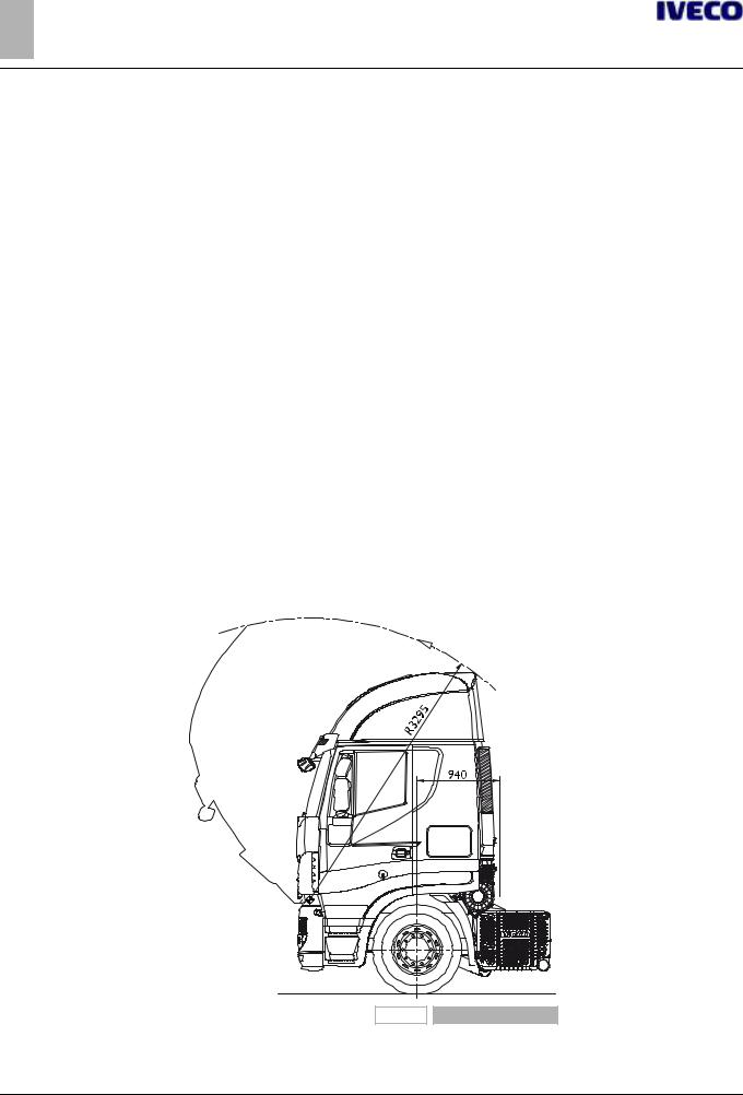
●freedom of cab tilting must be provided; in Figure 1-7, the quotas of maximum longitudinal dimension of the cab and radius of rotation are indicated;
195914 |
Figure 7 |
– Printed 603.95.513 – Base 06/2013

STRALIS Euro 6 ‒ GENERAL INFORMATION
GENERAL INFORMATION 17 1.17 CONVENTIONS
Note due to the new location of the air filter on the Stralis Hi-Way, the minimum distance between the centre line of the front axle and the body of the trailer is increased by 20 mm, from 920 to 940 mm.
The minimum distances on the Euro 6 versions are therefore:
– Stralis Hi-Way: 940 mm (+ 20 mm compared to the Euro 5 version); – Stralis Hi-Road: 900 mm (unchanged compared to the Euro 5 version); – Stralis Hi-Street: 445 mm (unchanged compared to the Euro 5 version).
●The possibility of disassembling the various groups for assistance operations must be maintained. Any servicing on the transmission/clutch or controls (e.g. suspension bars) must be carried out without removing important parts of the added structure;
●conditions should not be affected regarding cooling (radiator grille, radiator, air passages, cooling etc.), fuel supply (pump positioning, filters, pipe diameter, etc.) and engine air intake;
●panels for noise emission levels must not be altered or moved so as not to vary the approved sound emission limits. If there are any openings (e.g. for the passage of the longitudinal sections of the chassis), they must be thoroughly closed, using fireproof materials and soundproofing materials, equivalent to the original materials used;
●adequate ventilation must be maintained for the brakes and battery casing (particularly in the execution of truck bodies);
●in the placement of fenders and wheel arches, free shaking of the rear wheels must be guaranteed, even under the conditions of use with chains. It must also be guaranteed enough space for the lifting axle tyres. Some models include steering of the 3rd axle in the raised position as well: respect the spaces necessary for this function (see Chapter 2.21);
●adjustment of the vehicle's headlamps must be checked once construction is completed, to correct any changes in their structure; for adjustment, proceed according to the instructions given in the "Use and Maintenance" manual;
●for any elements supplied loose (e.g. spare wheel, chocks), the Bodybuilder must position and fasten them in an accessible and secure way, in compliance to any national regulations.
1.17 CONVENTIONS
In these Guidelines the following conventions are adopted:
● Wheelbase: distance between the centre lines of the first steering axle and the first rear axle (engine or not).
● Rear overhang: distance between the centre line of the last axle and the rear extremity of the chassis side members.
● Dimensions A, B and t of the chassis section: see the picture on the side.
91473 |
|
Figure 8 |
– Printed 603.95.513 – Base 06/2013

STRALIS Euro 6 ‒ GENERAL INFORMATION
18 GENERAL INFORMATION
– Printed 603.95.513 – Base 06/2013

SECTION 2
CHASSIS
INTERVENTIONS
- Printed 603.95.513 – Base 06/2013

- Printed 603.95.513 – Base 06/2013

STRALIS Euro 6 ‒ CHASSIS INTERVENTIONS
CHASSIS INTERVENTIONS |
3 |
Index |
|
|
|
Index |
|
2.1 GENERAL CHASSIS MODIFICATION |
|
STANDARDS . . . . . . . . . . . . . . . . . . . . . . . . . . . |
5 |
Preventive measures . . . . . . . . . . . . . . . . . . . . |
5 |
Characteristics of the material used in chassis |
|
modifications . . . . . . . . . . . . . . . . . . . . . . . . . |
6 |
Stresses on the chassis . . . . . . . . . . . . . . . . . . . |
7 |
2.2 DRILLS ON THE CHASSIS . . . . . . . . . . . . . . . |
7 |
Hole position and size . . . . . . . . . . . . . . . . . . . |
7 |
Screws and nuts . . . . . . . . . . . . . . . . . . . . . . . |
8 |
Welds . . . . . . . . . . . . . . . . . . . . . . . . . . . . . |
8 |
Sealing holes by welding . . . . . . . . . . . . . . . . . |
10 |
2.3 RUST AND PAINT PROTECTION . . . . . . . . . |
10 |
Original vehicle parts . . . . . . . . . . . . . . . . . . . |
11 |
Added or modified parts . . . . . . . . . . . . . . . . . |
13 |
Precautions . . . . . . . . . . . . . . . . . . . . . . . . . |
13 |
2.4 WHEELBASE MODIFICATION . . . . . . . . . . . |
14 |
General information . . . . . . . . . . . . . . . . . . . . |
14 |
Authorisation . . . . . . . . . . . . . . . . . . . . . . . . |
14 |
Effects on steering . . . . . . . . . . . . . . . . . . . . . |
15 |
Effects on braking . . . . . . . . . . . . . . . . . . . . . |
15 |
Intervention procedure . . . . . . . . . . . . . . . . . . |
16 |
Checking chassis stress . . . . . . . . . . . . . . . . . . |
16 |
Cross members . . . . . . . . . . . . . . . . . . . . . . |
16 |
Gearbox modifications . . . . . . . . . . . . . . . . . . |
17 |
2.5 REAR OVERHANG MODIFICATION . . . . . . . |
17 |
General information . . . . . . . . . . . . . . . . . . . . |
17 |
Authorisation . . . . . . . . . . . . . . . . . . . . . . . . |
17 |
Chassis Shortening . . . . . . . . . . . . . . . . . . . . |
18 |
Elongation . . . . . . . . . . . . . . . . . . . . . . . . . . |
18 |
2.6 INSTALLING THE TOW HOOK . . . . . . . . . . |
19 |
General information . . . . . . . . . . . . . . . . . . . . |
19 |
Precautions for Installation . . . . . . . . . . . . . . . |
19 |
Towing hooks for conventional trailers . . . . . . . . |
20 |
Drawbar couplings for centre axle trailers . . . . . . |
20 |
Rear crossbar in lowered position . . . . . . . . . . . |
22 |
2.7 ASSEMBLING AN ADDITIONAL AXLE . . . . . . |
33 |
General information . . . . . . . . . . . . . . . . . . . . |
33 |
Reinforcements on the chassis . . . . . . . . . . . . . |
33 |
Added axle . . . . . . . . . . . . . . . . . . . . . . . . . |
34 |
Steering axles . . . . . . . . . . . . . . . . . . . . . . . . |
35 |
Suspension . . . . . . . . . . . . . . . . . . . . . . . . . |
35 |
Stabiliser bars . . . . . . . . . . . . . . . . . . . . . . . . |
36 |
Attachments to the chassis . . . . . . . . . . . . . . . |
36 |
Brake system . . . . . . . . . . . . . . . . . . . . . . . . |
36 |
Lifting device . . . . . . . . . . . . . . . . . . . . . . . . |
37 |
2.8 GEARBOX MODIFICATION . . . . . . . . . . . . |
37 |
Lengths allowed . . . . . . . . . . . . . . . . . . . . . . |
37 |
Positioning the sections . . . . . . . . . . . . . . . . . |
40 |
2.9 MODIFYING THE ENGINE AIR INTAKE AND |
|
EXHAUST SYSTEMS . . . . . . . . . . . . . . . . . . . . . |
42 |
Intake . . . . . . . . . . . . . . . . . . . . . . . . . . . . |
42 |
Engine exhaust . . . . . . . . . . . . . . . . . . . . . . . |
43 |
2.10 MODIFYING THE ENGINE COOLING |
|
SYSTEM . . . . . . . . . . . . . . . . . . . . . . . . . . . . . |
43 |
2.11 INSTALLING AN ADDITIONAL HEATING |
|
SYSTEM . . . . . . . . . . . . . . . . . . . . . . . . . . . . . |
44 |
2.12 INSTALLING AN AIR CONDITIONING |
|
SYSTEM . . . . . . . . . . . . . . . . . . . . . . . . . . . . . |
44 |
2.13 WORK ON THE CAB . . . . . . . . . . . . . . . . |
45 |
General information . . . . . . . . . . . . . . . . . . . . |
45 |
Work on the roof . . . . . . . . . . . . . . . . . . . . . |
46 |
2.14 CHANGING TYRE SIZE . . . . . . . . . . . . . . . |
46 |
2.15 WORK ON THE BRAKING SYSTEM . . . . . . |
47 |
General information . . . . . . . . . . . . . . . . . . . . |
47 |
Brake pipes . . . . . . . . . . . . . . . . . . . . . . . . . |
47 |
ABS electronic brake control devices . . . . . . . . . |
50 |
Withdrawing air from the cooling system . . . . . . |
50 |
2.16 ELECTRICAL SYSTEM: CURRENT |
|
INTERVENTIONS AND DRAWS . . . . . . . . . . . . . |
51 |
2.17 PART RELOCATION AND ANCHORAGE OF |
|
ADDITIONAL UNITS AND EQUIPMENT . . . . . . . . |
51 |
– Printed 603.95.513 – Base 06/2013

STRALIS Euro 6 ‒ CHASSIS INTERVENTIONS
4CHASSIS INTERVENTIONS Index
2.18 TRANSPORT OF HAZARDOUS MATERIALS |
|
(ADR) . . . . . . . . . . . . . . . . . . . . . . . . . . . . . . |
53 |
2.19 INSTALLING A RETARDER . . . . . . . . . . . . |
54 |
2.20 MODIFYING THE UNDER-RUN |
|
PROTECTION BAR . . . . . . . . . . . . . . . . . . . . . . |
54 |
2.21 REAR MUD GUARDS AND WHEEL |
|
ARCHES . . . . . . . . . . . . . . . . . . . . . . . . . . . . . |
55 |
2.22 RAIN FLAP . . . . . . . . . . . . . . . . . . . . . . . |
56 |
2.23 SIDE PROTECTIONS . . . . . . . . . . . . . . . . |
56 |
2.24 WHEEL CHOCKS . . . . . . . . . . . . . . . . . . |
58 |
– Printed 603.95.513 – Base 06/2013
Loading...