


USE AND MAINTENANCE
USO E MANUTENZIONE
UTILISATION ET ENTRETIEN
BETRIEB UND WARTUNG
USO Y MANTENIMIENTO
NEF SERIES
ELECTRONIC INJECTION SYSTEM
MARINE ENGINES
Publication edited by Marketing - Adv. & Promotion Print L31900018 - 10/06

NEF SERIES
ELECTRONIC INJECTION SYSTEM
N40 ENT M25
N60 ENT M37
N60 ENT M40
N67 ENT M45
USE AND MAINTENANCE
INTRODUCTION |
|
We would like to thank you for buying an IVECO MOTORS product, |
|
and compliment you on your choice of engine. |
|
Before you carry out any operation involving the engine or its fittings, |
|
please read the contents of this manual carefully; compliance with the |
|
instructions provided in the manual is the best way to guarantee trouble- |
|
free, long term operation of the engine. |
ENGLISH |
provided by giving the sequence of operations to be carried out in order |
|
The contents of this manual refer to the standard configuration of the |
|
engine, and the illustrations are purely indicative. Some instructions are |
|
to allow the engine and/or its fittings to perform in a certain way. In |
|
some cases they will be dependent on the configuration of the |
|
commands and the set-up of the vessel on which the engine is installed; |
|
for any points that differ from the contents of this manual, please consult |
|
the instructions provided by the Boatbuilder or a specific manual. |
|
The information provided below was current at the date of publication. |
|
The Manufacturer reserves the right to make modifications at any time |
|
without prior notice, for technical or commercial reasons or to update |
|
the engines to comply with legal requirements in the various Countries. |
|
The Manufacturer declines all liability for any errors or omissions. |
|
Please remember that the IVECO MOTORS Technical Service Network is available to offer you its experience and professional skills, wherever you may be.
1
CONTENTS |
Page |
GENERAL INFORMATION . . . . . . . . . . . . . . . . . . . . . . . . . . . . . .3 Guarantee . . . . . . . . . . . . . . . . . . . . . . . . . . . . . . . . . . . . . . . . . . . . . .3 Spare Parts . . . . . . . . . . . . . . . . . . . . . . . . . . . . . . . . . . . . . . . . . . . . .3 Liability . . . . . . . . . . . . . . . . . . . . . . . . . . . . . . . . . . . . . . . . . . . . . . . . .3 Safety . . . . . . . . . . . . . . . . . . . . . . . . . . . . . . . . . . . . . . . . . . . . . . . . . .3 Engine technical data N40 ENT M25. . . . . . . . . . . . . . . . . . . . . . . .4 Engine technical data N60 ENT M37/M40 . . . . . . . . . . . . . . . . . . .6 Engine technical data N40 ENT M25. . . . . . . . . . . . . . . . . . . . . . . .8 Signs . . . . . . . . . . . . . . . . . . . . . . . . . . . . . . . . . . . . . . . . . . . . . . . . . .10
USE. . . . . . . . . . . . . . . . . . . . . . . . . . . . . . . . . . . . . . . . . . . . . . . . . . .11 Preliminary checks. . . . . . . . . . . . . . . . . . . . . . . . . . . . . . . . . . . . . . .11 Starting and stopping the engine . . . . . . . . . . . . . . . . . . . . . . . . . . .11 Starting and stopping the engine from
the analogue control panel . . . . . . . . . . . . . . . . . . . . . . . . . . . . . . .12 Recognising alarms . . . . . . . . . . . . . . . . . . . . . . . . . . . . . . . . . . . . . .15 Starting and stopping the engine from
the digital control panel . . . . . . . . . . . . . . . . . . . . . . . . . . . . . . . . . .16 Recognising alarms . . . . . . . . . . . . . . . . . . . . . . . . . . . . . . . . . . . . . .18 Managing the engine from the Relay box . . . . . . . . . . . . . . . . . . .21 Proper use of the engine . . . . . . . . . . . . . . . . . . . . . . . . . . . . . . . . .22 Special warnings . . . . . . . . . . . . . . . . . . . . . . . . . . . . . . . . . . . . . . . .22 Running in . . . . . . . . . . . . . . . . . . . . . . . . . . . . . . . . . . . . . . . . . . . . .23 Refuelling . . . . . . . . . . . . . . . . . . . . . . . . . . . . . . . . . . . . . . . . . . . . . .24
CONTROLS AND MAINTENANCE . . . . . . . . . . . . . . . . . . . . .25 Maintenance personnel . . . . . . . . . . . . . . . . . . . . . . . . . . . . . . . . . .25 Accident prevention . . . . . . . . . . . . . . . . . . . . . . . . . . . . . . . . . . . . .25 Frequency . . . . . . . . . . . . . . . . . . . . . . . . . . . . . . . . . . . . . . . . . . . . .26 Requirements . . . . . . . . . . . . . . . . . . . . . . . . . . . . . . . . . . . . . . . . . .28 How to proceed . . . . . . . . . . . . . . . . . . . . . . . . . . . . . . . . . . . . . . . .28 Moving the engine . . . . . . . . . . . . . . . . . . . . . . . . . . . . . . . . . . . . . .35 Disposal of waste . . . . . . . . . . . . . . . . . . . . . . . . . . . . . . . . . . . . . . .35
Page
LONG PERIODS OF INACTIVITY . . . . . . . . . . . . . . . . . . . . . . .36 Preparing the engine for a long period of inactivity . . . . . . . . . . .36 Restarting the engine after a long period of inactivity . . . . . . . . .37ENGINE MALFUNCTIONS . . . . . . . . . . . . . . . . . . . . . . . . . . . . .38
EMERGENCIES ON BOARD . . . . . . . . . . . . . . . . . . . . . . . . . . . .39IN APPENDIX . . . . . . . . . . . . . . . . . . . . . . . . . . . . . . . . . . . . . . . . . . .
Oil viscosity level according to surrounding temperatures . . . . . . .
2

GENERAL INFORMATION
GUARANTEE
In order to ensure that your engine gives the best possible performance and to take advantage of the IVECO MOTORS guarantee, you must follow the indications provided in this publication with great care; failure to do so may result in invalidation of the guarantee.
SPARE PARTS
Always use Original IVECO MOTORS Spare parts. This is essential to keep the engine in original running order.
The use of non-original spare parts will not only invalidate the guarantee, but will mean that IVECO MOTORS will not be considered liable in any way during the whole working life of the engine.
LIABILITY
The Manufacturer will only be considered liable subject to performance of the control and maintenance operations indicated and described in this manual; to this effect, proof that these operations have been performed must be provided. Any special maintenance operations that may be necessary must be carried out by qualified technicians from authorised Workshops in the IVECO MOTORS Network, using the instruments and equipment provided for the purpose.
SAFETY
The following information is intended to encourage caution when using the engine, so as to avoid damage to persons or property as a result of improper or incorrect behaviour.
The engines must only be used for the purposes indicated by the |
|
Manufacturer. |
|
Any tampering, modification and use of non-original spare parts |
ENGLISH |
may compromise proper operation of the engine and safe |
|
navigation; never, under any circumstances make |
|
modifications to the wiring and to the units equipping the engine, |
|
or connect them to other power systems. |
|
Pay particular attention to moving parts of the engine, to high |
|
temperature components and to circuits containing pressurised |
|
fluids; its electrical equipment houses electrical currents and |
|
voltage. |
|
The exhaust fumes produced by the engine are bad for your health. |
|
The engine must only be moved using suitable lifting tackle, making |
|
use of the U-bolts provided on the engine for that purpose. |
|
The engine must not be started up and used until the vessel in |
|
which it installed has satisfied all necessary safety requirements, or |
|
until the vessel has been guaranteed to comply with local laws and |
|
regulations. |
|
The operations required to guarantee the best possible use and |
|
preservation of the engine must only be carried out by persons of |
|
proven experience, equipment with tools considered suitable by |
|
IVECO MOTORS. |
|
For the purpose of safety, further recommendations are given in the chapter CONTROLS AND MAINTENANCE.
3

ENGINE TECHNICAL DATA N40 ENT M25
The technical code and serial number are indicated on a plate, which is located on different parts of the engine, according to the model: flywheel casing, tappet cover, coolant tank.
Code |
N40 ENT M25 |
|
|
Engine family |
F4 |
|
|
Cycle |
4-stroke diesel |
|
|
Number and arrangement |
|
of cylinders |
4, in line |
|
|
Bore x stroke |
102 x 120 mm |
|
|
Total displacement |
3.900 cm3 |
|
|
Air system |
Supercharged aftercooled |
|
(TCA or TAA) |
|
|
Injection type |
Direct/Common rail |
|
electronically managed |
|
|
Engine direction of rotation |
Anticlockwise |
|
(seen from flywheel side) |
|
|
Dry weight |
490 kg |
|
|
Electrical system |
12 V (24 V on request) |
|
|
Accumulator/s |
|
- capacity |
180 Ah or above |
- discharge current |
800 A or above |
|
|
Available settings (*) |
N40 ENT M25 |
|
|
A1 |
184 kW (250 CV) @ 2800 rpm |
|
|
B |
147 kW (200 CV) @ 2800 rpm |
|
|
C |
125 kW (170 CV) @ 2800 rpm |
|
|
(*)Net power to the flywheel in compliance with ISO 3046-1. Test conditions: T 25 °C; atmospheric pressure 100 kPa; relative humidity 30%.
WARNING
Any alteration of the above mentioned characteristics, in particular modification of the data stored in the injection system electronic units or the characteristics of the engine and its fittings, is strictly prohibited, penalty invalidation of the guarantee and absence of all liability on the part of IVECO MOTORS.
4

|
|
|
|
|
|
04_363_N
Engine NEF N40 ENT M25
1. Exhaust gas and sea water discharge - 2. Turbocharger - 3. Engine coolant-sea water heat exchanger - 4. Coolant outlet manifold from
engine - 5. Oil filter |
- |
6. Lifting U-bolt - 7. Coolant filler cap - |
||||
8. Thermostat |
valve |
location - 9. Alternator |
- |
10. Manifold |
||
connecting |
the |
cooling |
circuit to the coolant tank - 11. Coolant |
|||
infeed to |
engine - |
|
12. Water-heater system |
tap |
or plug - |
|
13. Connection to battery positive terminal - 14. Coolant discharge plug - 15. Electrical starter motor - 16. Removable anode.
|
|
|
|
|
|
|
|
|
|
ENGLISH |
04_364_N
|
|
|
|
|
|
|
Engine NEF N40 ENT M25
1. Coolant expansion tank - 2. Oil extraction pump - 3. Oil dipstick - 4. Oil filler cap - 5. Common rail divider - 6. Sea water pump inlet - 7. Lifting U-bolt - 8. Oil vapour filter - 9. Sea water circuit connector pipe - 10. Air filter - 11. High-pressure pump for common rail system - 12. Fuel inlet from tank - 13. Fuel outlet to tank - 14. Fuel filter - 15. Removable anode - 16. Accelerator voltage divider lever - 17. Sea water discharge plug - 18. Auxiliary member pulley casing.
5
ENGINE TECHNICAL DATA N60 ENT M37 / M40
The technical code and serial number are indicated on a plate, which is located on different parts of the engine, according to the model: flywheel casing, tappet cover, coolant tank.
Code |
N60 ENT M37 / M40 |
|
|
Engine family |
F4 |
|
|
Cycle |
4-stroke diesel |
|
|
Number and arrangement |
|
of cylinders |
6, in line |
|
|
Bore x stroke |
102 x 120 mm |
|
|
Total displacement |
5.900 cm3 |
|
|
Air system |
Supercharged aftercooled |
|
(TCA or TAA) |
|
|
Injection type |
Direct/Common rail |
electronically |
managed |
|
|
Engine direction of rotation |
Anticlockwise |
|
(seen from flywheel side) |
|
|
Dry weight |
595 kg |
|
|
Electrical system |
12 V (24 V on request) |
|
|
Accumulator/s |
|
- capacity |
180 Ah or above |
- discharge current |
800 A or above |
|
|
Available settings (*) |
N60 ENT M37 |
|
|
A1 |
272 kW (370 CV) @ 2800 rpm |
|
|
B |
243 kW (330 CV) @ 2800 rpm |
|
|
C |
199 kW (270 CV) @ 2800 rpm |
|
|
Available settings (*) |
N60 ENT M40 |
|
|
A1 |
294 kW (400 CV) @ 3000 rpm |
|
|
A2 |
272 kW (370 CV) @ 3000 rpm |
|
|
B |
243 kW (330 CV) @ 3000 rpm |
|
|
C |
199 kW (270 CV) @ 3000 rpm |
|
|
(*)Net power to the flywheel in compliance with ISO 3046-1. Test conditions: T 25 °C; atmospheric pressure 100 kPa; relative humidity 30%.
WARNING
Any alteration of the above mentioned characteristics, in particular modification of the data stored in the injection system electronic units or the characteristics of the engine and its fittings, is strictly prohibited, penalty invalidation of the guarantee and absence of all liability on the part of IVECO MOTORS.
6

1 |
2 |
3 |
4 |
5 |
6 |
7 |
8 |
9 |
04_352_N |
|
|
|
|
|
|
16 |
15 |
14 |
13 |
12 |
11 |
10 |
Engine NEF N60 ENT M37/M40
1. Exhaust gas and sea water discharge - 2. Turbocharger - 3. Engine coolant-sea water heat exchanger - 4. Coolant outlet manifold from
engine - 5. Oil |
filter - 6. Lifting U-bolt - 7. Coolant filler cap - |
8. Thermostat |
valve location - 9. Alternator - 10. Manifold |
connecting the cooling circuit to the coolant tank - 11. Coolant infeed to engine - 12. Water-heater system tap or plug - 13. Coolant discharge plug - 14. Connection to battery positive terminal - 15. Electrical starter motor - 16. Removable anode.
1 |
2 |
3 |
4 |
5 |
6 |
7 |
8 |
9 |
10 |
ENGLISH |
|
|
|
|
|
|
|
04_353_N |
18 |
17 |
16 |
15 |
14 |
13 |
12 |
11 |
Engine NEF N60 ENT M37/M40
1. Coolant expansion tank - 2. Oil extraction pump - 3. Oil filler cap - 4. Oil dipstick - 5. Common rail divider - 6. Sea water pump inlet - 7. Lifting U-bolt - 8. Oil vapour filter - 9. Sea water circuit connector pipe - 10. Air filter - 11. High-pressure pump for common rail system - 12. Fuel inlet from tank - 13. Fuel outlet to tank - 14. Fuel filter - 15. Removable anode - 16. Accelerator voltage divider lever - 17. Sea water discharge plug - 18. Auxiliary member pulley casing.
7

ENGINE TECHNICAL DATA N67 ENT M45
The technical code and serial number are indicated on a plate, which is located on different parts of the engine, according to the model: flywheel casing, tappet cover, coolant tank.
Code |
N67 ENT M45 |
|
|
Engine family |
F4 |
|
|
Cycle |
4-stroke diesel |
|
|
Number and arrangement |
|
of cylinders |
6, in line |
|
|
Bore x stroke |
102 x 120 mm |
|
|
Total displacement |
5.900 cm3 |
|
|
Air system |
Supercharged aftercooled |
|
(TCA or TAA) |
|
|
Injection type |
Direct/Common rail |
electronically |
managed |
|
|
Engine direction of rotation |
Anticlockwise |
|
(seen from flywheel side) |
|
|
Dry weight |
595 kg |
|
|
Electrical system |
12 V (24 V on request) |
|
|
Accumulator/s |
|
- capacity |
180 Ah or above |
- discharge current |
800 A or above |
|
|
Available settings (*) |
N67 ENT M45 |
|
|
A1 |
331 kW (450 CV) @ 3000 rpm |
|
|
A2 |
309 kW (420 CV) @ 3000 rpm |
|
|
B |
272 kW (370 CV) @ 3000 rpm |
|
|
C |
258 kW (350 CV) @ 3000 rpm |
|
|
(*)Net power to the flywheel in compliance with ISO 3046-1. Test conditions: T 25 °C; atmospheric pressure 100 kPa; relative humidity 30%.
WARNING
Any alteration of the above mentioned characteristics, in particular modification of the data stored in the injection system electronic units or the characteristics of the engine and its fittings, is strictly prohibited, penalty invalidation of the guarantee and absence of all liability on the part of IVECO MOTORS.
8

1 |
2 |
3 |
4 |
5 |
6 |
7 |
8 |
9 |
04_352_N |
|
|
|
|
|
|
16 |
15 |
14 |
13 |
12 |
11 |
10 |
Engine NEF N67 ENT M45
1. Exhaust gas and sea water discharge - 2. Turbocharger - 3. Engine coolant-sea water heat exchanger - 4. Coolant outlet manifold from
engine - 5. Oil |
filter - 6. Lifting U-bolt - 7. Coolant filler cap - |
8. Thermostat |
valve location - 9. Alternator - 10. Manifold |
connecting the cooling circuit to the coolant tank - 11. Coolant infeed to engine - 12. Water-heater system tap or plug - 13. Coolant discharge plug - 14. Connection to battery positive terminal - 15. Electrical starter motor - 16. Removable anode.
1 |
2 |
3 |
4 |
5 |
6 |
7 |
8 |
9 |
10 |
ENGLISH |
|
|
|
|
|
|
|
04_353_N |
18 |
17 |
16 |
15 |
14 |
13 |
12 |
11 |
Engine NEF N67 ENT M45
1. Coolant expansion tank - 2. Oil extraction pump - 3. Oil filler cap - 4. Oil dipstick - 5. Common rail divider - 6. Sea water pump inlet - 7. Lifting U-bolt - 8. Oil vapour filter - 9. Sea water circuit connector pipe - 10. Air filter - 11. High-pressure pump for common rail system - 12. Fuel inlet from tank - 13. Fuel outlet to tank - 14. Fuel filter - 15. Removable anode - 16. Accelerator voltage divider lever - 17. Sea water discharge plug - 18. Auxiliary member pulley casing.
9
SIGNS
Certain warning signs are affixed to the engine, and their meanings are indicated below.
NOTE: The signs with an exclamation mark on them underline a potential danger.
Lifting point (engine only).
Fuel Cap
(on the fuel tank, if there is one).
Oil Cap.
Oil dipstick.
Danger of burning:
Expulsion of hot water under pressure.
Danger of burning:
Presence of high temperature parts.
Danger of fire:
Fuel present.
Danger of impact or catching on moving parts:
Presence of fans, pulleys, belts or the like.
10
USE
PRELIMINARY CHECKS
Before starting the engine each time:
Make sure that the sea-water inlet valve is open. Operation of the sea water pump without water would cause irreparable damage to the internal rotor within a very few seconds.
Check the level of technical fluids (fuel, engine oil and coolant).
CAUTION!
Before starting the engine, make sure that no combustible vapours or gasses are present in the engineroom.
STARTING AND STOPPING THE ENGINE
For vessels equipped with instrument panels that are not manufactured by IVECO MOTORS
The start-up and shut-down operations described below apply to an on- |
|
board control panel manufactured by IVECO MOTORS; if the vessel is |
|
fitted with an instrument panel that has been customised by the |
|
Boatbuilder or Fitter, these operations may vary according to the various |
ENGLISH |
choices made during construction. In these cases, follow the start-up/ |
|
shut-down sequence and use the instrument panel description provided |
|
by the Boatbuilder on specific documentation. |
11
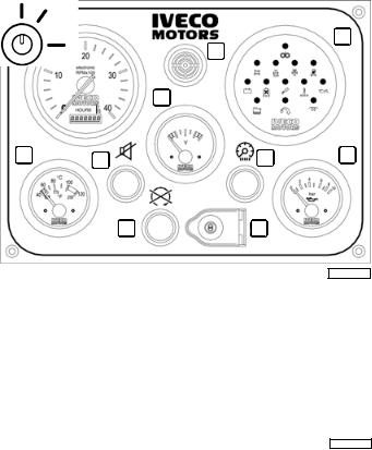
STARTING AND STOPPING THE ENGINE FROM THE ANALOGUE CONTROL PANEL
Procedure for start-up from the main IVECO MOTORS control panel (supplied on demand)
Make sure that the electrical switch indicating ENGINE ROOM - BRIDGE on the Relay Box unit (normally located in the engine room) is in the BRIDGE position, then proceed as follows:
1.Lift the protective cover over the key switch (8), insert the key and turn it to the right to position 8B.
2.Make sure that the analogue instruments are showing values that conform with the relevant physical parameters (temperature, battery voltage and oil pressure).
3.Wait for the beeper to stop sounding and for the alarm indicator lights on the indicator module (5) to switch off, with the exception of the “alternator recharge” and “low oil pressure” indicators. At the same time, check that the indicator test has been performed successfully (information on how to interpret this test and indications on the module are given in the relevant paragraph).
4.Turn the key to position 8C; once the engine has started, release the key and do not accelerate.
5.Make sure that the analogue instruments are showing values that conform with the relevant physical parameters (temperature, battery voltage and oil pressure).
6.If the engine does not start, after releasing the key it will only be possible to turn it back to the start position after first returning the switch to the rest position 8A.
2 |
5 |
4
3
1 |
10 |
7 |
6 |
9 |
8 |
04_354_N
1. Coolant temperature indicator - 2. Rev counter and hour counter - 3. Voltmeter - 4. Beeper - 5. Indicator and alarm module - 6. Engine oil pressure indicator - 7. Control panel instrument light switch - 8. Key switch to start/stop the engine - 9. Button to stop the engine - 10. Button to disable the beeper.
Detail of the key switch |
8A |
8B |
8C
04_356_N
12
 Loading...