


NEF
N40 ENT M25
N60 ENT M37 - M40
4 - 6 cylinders in line Diesel Cycle
For marine applications
INSTALLATION DIRECTIVE
MAY 2006 EDITION
T E C H N O L O G I C A L E X C E L L E N C E

|
N40 ENT M25 |
INSTALLATIONDIRECTIVE |
MAY 2006 |
|
N60 ENT M37-M40 |
||
|
|
|
|
|
|
|
|
FOREWORD
We strongly recommend that you carefully read the indications contained in this document: compliance with them protects the engine against irregular operation and assures its reliability, safeguarding sea-going and maintenance personnel against accident hazards.
The indications contained in this directive pertain to the N40 ENT M25, N60 ENT M37 and N60 ENT M40 engines and complement the IVECO MOTORS publication “Guide to the Installation of Marine Engines” the reader should refer to, for anything that is not explained herein.
For more complete information about the engine, please refer to the appropriate technical brochure.
Use of fuels and oils with different characteristics from those set out in the operation and maintenance manual may compromise the regular operation of the engine, limiting its performance, reliability and working life.
Exclusive use of IVECO Original Parts is a necessary condition to maintain the engine in its original integrity.
Tampering, making modifications and using non original parts can jeopardize the safety of boat engineers and users.
To obtain spare parts, you must indicate:
-Commercial code, serial number and indications shown on the engine tag;
-Part number of the spare as per spare part catalog.
The information provided below refer to engine characteristics that are current as of the publication date.
IVECO MOTORS reserves the right to make modifications at any time and without advance notice, to meet technical or commercial requirements or to comply with local legal and regulatory requirements.
We refuse all liability for any errors and omissions.
The reader is reminded that the IVECO MOTORS Technical Assistance Network is always at the Customer’s side with its competence and professionalism.
Publication IVECO MOTORS edited by:
IVECO PowerTrain
Advertising & Promotion
Pregnana Milanese (MI)
www.ivecomotors.com
Printed P3D64N001 E - May 2006 Edition

MAY 2006 |
INSTALLATIONDIRECTIVE |
N40 ENT M25 |
|
|
N60 ENT M37-M40 |
||||
|
|
|
||
|
|
|
|
Indications for consultation
The different versions of the motors are generally hown using the same pictures and descriptions, however important differences are shown separately.
CAUTION
During the year 2005, some modifications were made to the internal circuits of the relay box and to the wiring. These modifications make incompatible and harmful the use of the components supplied now together with the components supplied before. Please refer to the instruction shown in Chapter 8.
CONTENTS
|
Page |
|
|
|
|
1. |
WARNINGS AND CAUTIONS |
4 |
|
|
|
2. |
ENGINE PARTS AND COMPONENTS |
6 |
|
|
|
3. |
INSTALLATION OVERVIEW |
8 |
|
|
|
4. |
GENERAL INSTALLATION CRITERIA |
9 |
|
|
|
5. |
TECHNICAL DATA FOR INSTALLATION |
10 |
|
|
|
6. |
IDENTIFICATION DATA |
12 |
|
|
|
7. |
FUEL LINE |
13 |
|
|
|
8. |
ELECTRICAL EQUIPMENT |
16 |
|
|
|
9. |
MAIN ANALOG INSTRUMENT PANEL |
24 |
|
|
|
10. |
SECONDARY ANALOG INSTRUMENT PANEL |
28 |
|
|
|
11. |
DRILLING PLANS FOR ANALOG PANELS |
29 |
|
|
|
12. |
MAIN DIGITAL INSTRUMENT PANEL |
30 |
|
|
|
13. |
SECONDARY DIGITAL INSTRUMENT PANEL |
36 |
|
|
|
14. |
DRILLING PLAN FOR DIGITAL PANELS |
37 |
|
|
|
15. |
CUSTOMIZED INSTRUMENT PANEL |
38 |
|
|
|
16. |
SENSORS FOR DETECTION |
|
|
AND PANEL SIGNALING |
40 |
|
|
|
17. |
PREPARING THE ENGINE FOR FIRST START-UP |
42 |
|
|
|
18. |
TESTS BEFORE THE FIRST START-UP |
42 |
|
|
|
19. |
FIRST ENGINE START |
43 |
|
|
|
20. |
EDC ANOMALIES INDICATION |
44 |
|
|
|
21. |
BLINK CODE TABLE |
45 |
|
|
|
22. |
UNDERWAY CHECKS |
47 |
|
|
|
23. |
PREPARING THE ENGINE |
|
|
FOR LONG IDLE PERIODS |
48 |
|
|
|
24. |
WIRING DIAGRAMS |
49 |
|
|
|
25. |
APPENDIX |
65 |
|
|
|

|
N40 ENT M25 |
INSTALLATIONDIRECTIVE |
MAY 2006 |
|
N60 ENT M37-M40 |
||
|
|
|
|
|
|
|
|
1. WARNINGS AND CAUTIONS
To obtain the best engine performance, it is essential not to deviate from the mission profile for which it was produced and set up.The engine must not be used for purposes other than those stated by the manufacturer. IVECO MOTORS is willing to examine any need for particular installations beforehand. Use of an electronically controlled injection system, in providing the engine with performance benefits, requires that the installer and maintenance specialist comply with some fundamental rules, which will become more and more commonplace as use of such equipment becomes progressively more widespread. Boat outfitters and maintenance specialists are invited to closely follow the instructions contained herein. No modifications to the engine, its accessories and components, are allowed.
Failure to comply with the instructions that follow shall void the warranty and relieve IVECO MOTORS of all liabilities.
For personnel safety
Specialists and installers are cautioned to comply with workplace safety rules and to adopt prescribed individual protection devices when working.
oDrain the cooling, lubrication and fuel lines only after the fluids have duly cooled. The pressurized cap of the water line may be opened only after the engine has duly cooled.
oBatteries contain a highly corrosive sulfuric acid solution: must never be upset and must be handled with the utmost caution to prevent spillage. Ensure that the battery compartment is adequately ventilated.
Handling
The engine must be handled by experienced personnel, using the prescribed tool or a rocker arm that keeps the lifting lines parallel and with adequate equipment in terms of capacity and size.The two eyebolts provided for lifting the engine alone must always be used simultaneously.
Installation
oKnife switches or battery breakers may be used on the power supply line of the engine electronic unit, provided they are not used to shut the engine off.
oDo not modify the wiring harnesses; their length may not be modified: use only available extensions.
oDo not use electronic device wiring harnesses not compliant with the IVECO MOTORS directive, in terms of length, type of conductor, location, clamping, connection of the shielding and earth braids.
oTo avoid any interference, the wiring harnesses of the different on-board electronic devices must follow different paths from those of the engine electronic systems.
oDo not connect any extraneous user device to the engine electrical equipment.
oDo not place voltage across the boat’s on-board electrical system without first verifying that there are no short circuits.
oDo not branch pipes off to draw fuel from the engine supply lines.
oDo not make any change to the engine’s hydraulic circuits and components.
oDo not execute arc welding operations before removing the electronic units from their seating, placing them at an adequate safety distance.
oDo not subject electronic units to temperatures exceeding 80 °C.
oDo not paint electrical components and their connections.
oDo not alter the data contained in the engine control electronic unit.
oComply with prescribed procedures and torque values when tightening threaded elements.
Start-up
oReady the engine following the procedure set out in Chapter 17.
oWhen starting the engine the first time, have suitable means available to cut off air intake in case of a runaway condition.
oStart the engine after ensuring that it is complete with every part specified by the manufacturer and required by the installation, without attempting to start it with caps and occlusions to the lubrication, cooling and fuel feed lines.
oCheck that the fluid lines are perfectly sealed, especially lines for fuels and lubricants, which may cause fires and consequent harm to persons and equipment.
oMake sure that the various pipelines are not in contact with warm surfaces or moving parts.
oThe installing yard is required to carry out tests to verify the functional compatibility between the electrical-elec- tronic equipment of the engine and the other electronic equipment present on the boat.
Tests and tuning up
oNever disconnect the batteries when the engine is running.
oRemove the electrical connections from the batteries before any operation on the electrical system.
oEnsure that the battery terminals comply with the exact polarity, are properly tightened and protected against accidental short circuits and corrosion phenomena.
oDo not connect or disconnect electrical connections when electrical power supply is present.

MAY 2006 |
INSTALLATIONDIRECTIVE |
N40 ENT M25 |
|
N60 ENT M37-M40 |
|
||
|
|
|
|
|
|
|
|
oDo not cause sparks in the attempt to verify the presence of electrical voltage.
oDo not draw fuel through unfiltered lines.
oDo not clean the engine and its parts with corrosive or abrasive detergent substances, to avoid compromising the integrity of electrical connections.
oThe engine fluids and air, water, and oil filters discarded after use must be properly stored and delivered to appropriate collection centers.
Long engine inactivity periods
Before long periods of inactivity, ready the engine following the procedure set out in Chapter 23.

|
N40 ENT M25 |
INSTALLATIONDIRECTIVE |
MAY 2006 |
|
N60 ENT M37-M40 |
||
|
|
|
|
|
|
|
|
2. ENGINE PARTS AND COMPONENTS
Figure 1
7 |
8 |
9 10 11
6
5 |
|
4 |
12 |
|
|
|
13 |
3
2
1
17
16 |
04_006_N |
|
15 14
1. Engine coolant discharge cap - 2. Electric starter motor - 3.Tube bundle engine coolant/sea water heat exchanger - 4. Location of sacrificial anode - 5. Cooled exhaust manifold - 6. Exhaust gas and sea water discharge pipeline - 7. Cap for engine coolant outlet to sanitary water heating system - 8. Lifting eyebolts - 9. Rocker arm cover - 10. Oil refill cap - 11. Coolant refill cap - 12. Location of thermostatic valve - 13. Engine coolant tank - 14. Auxiliary belt automatic tensioner - 15. Alternator - 16. Cap for engine coolant discharge and recirculation from sanitary water heating system - 17. Oil filter.

MAY 2006 |
INSTALLATIONDIRECTIVE |
N40 ENT M25 |
|
|
N60 ENT M37-M40 |
||||
|
|
|
||
|
|
|
|
Figure 2
12 |
13 |
14 |
15 |
16 |
11
10
9
8
7
17
6
04_007_N
5 |
4 |
3 |
2 |
1 |
1.Combustion air filter - 2. Common rail high pressure injection pump -3. Fuel filter - 4. Sea water pump - 5. Sea water inlet -
6.Throttle potentiometer - 7. Sacrificial anode - 8. Oil vapor separator - 9. Combustion air-sea water heat exchanger - 10. Location of sea water discharge cap - 11. Manual lubricating oil extraction pump - 12. Combustion air pressure and temperature sensor -
13. Oil dipstick - 14. Common rail distributor - 15. Air filter clogging sensor - 16. Cooled turbocharger - 17. Sea water junction pipe from after-cooler to engine coolant/sea water heat exchanger.

|
N40 ENT M25 |
INSTALLATIONDIRECTIVE |
MAY 2006 |
|
N60 ENT M37-M40 |
||
|
|
|
|
|
|
|
|
3. INSTALLATION OVERVIEW
Figure 3
1 |
2 |
11
10
3
04_071_N
9 |
8 |
7 |
6 |
5 |
4 |
1.Indicator and control panel - 2. Electrical panel with relay box and EDC electronic unit - 3. Exhaust gas and sea water discharge -
4.Filtered sea water intake - 5. Decanter filter - 6. Fuel feed pipe to the high pressure pump - 7. Fuel return pipe to tank - 8. Fuel
suction pipe - 9.Tank - 10.Throttle Bowden rod - 11.Throttle lever.
The figure shows the set of components of an installation, including those supplied with the engine equipment, standard or optional, and those supplied or produced by the yard.
It provides a comprehensive picture of the operations required to install the engine.
Components arrangement and illustrations are not binding but merely indicative, subject to the choices made by yard engineers according to their skills, available spaces and the prescriptions set out herein.

MAY 2006 |
INSTALLATIONDIRECTIVE |
N40 ENT M25 |
|
|
N60 ENT M37-M40 |
||||
|
|
|
||
|
|
|
|
4. GENERAL INSTALLATION CRITERIA
Accessibility
The engine must be located in such a way as to allow filling and draining engine liquids when doing servicing operations. Moreover, the relay box and the diagnostic push-button present on it must be accessible, also when underway.
Anchoring
If anchoring is accomplished by interposing shock mounts, they must be able to support the engine’s mass and the longitudinal thrust exerted by the propeller shaft in motion.
If rigid mounting is adopted, particular care must be given to support alignment and co-planarity.
Information on dimensions and fastening values are provided in the “Installation Diagram”.
Combustion and ventilation air
Compliance with prescriptions on the quantity of air required for combustion and ventilation assures a regular operation of the engine even in adverse conditions and it enables to deliver its maximum design power (1).
Sea water line
It must be provided with an intake capable of preventing the entry of foreign bodies into the suction pipes. Between the intake and the pump, it is best to interpose a gate to be closed in emergencies or for extended idle periods and a filter to stop the smaller impurities; it is also recommended to install a suitably dimensioned and easily replaced zinc anode.
The engine sea water line was provided by the manufacturer with protection anodes to be replaced periodically.
The rubber hoses positioned along the pipeline shall be sufficiently rigid not to create choked areas caused by crushing (1).
Engine pre-heating
If the engine usage profile requires immediate delivery of power at the highest rpm’s, it is recommended to install an auxiliary pre-heater on the closed cooling loop.
Exhaust gas discharge
The exhaust gas discharge conduit shall be compliant with the guidelines contained in the IVECO MOTORS publication “Guide to the installation of marine engines”; it also provides indications to compute the dimensions of the exhaust pipelines, which is the Yard’s responsibility.
Electric - electronic equipment
Provide a suitable arrangement of the engine control electronic unit, of the relay box and of the possible optional electronic units, referring to the dimensions and position of the wire harnesses and their connectors.
Both units must be anchored in such a way as to dampen the vibrations and stresses undergone by the hull while underway and/or induced by the engine’s operation.
(1)The EDC engine electronic control is programmed to reduce maximum deliverable power if the operating parameters measured by the sensors show that critical conditions have been reached, and if exceeded the engine could be damaged.

10 |
N40 ENT M25 |
INSTALLATIONDIRECTIVE |
MAY 2006 |
|
N60 ENT M37-M40 |
||||
|
|
|
||
|
|
|
|
5. TECHNICAL DATA FOR INSTALLATION |
|
|
|
|
|
|
|
|
N40 ENT |
N60 ENT |
N60 ENT |
|
|
|
M25 |
M37 |
M40 |
|
Combustion and ventilation air when underway |
|
|
|
|
|
|
|
|
|
|
|
Static vacuum allowed downstream of the air filter |
kPa |
≤ 3,5 |
≤ 3,5 |
≤ 3,5 |
|
mm H2O |
≤ 350 |
≤ 350 |
≤ 350 |
|
|
|
||||
|
Combustion air flow rate |
m3/h |
≥ 900 |
≥ 1050 |
≥ 1150 |
|
Engine room ventilation air flow rate (excluding combustion air) |
m3/h |
≥ 3100 |
≥ 4700 |
≥ 5050 |
|
Static vacuum allowed in the engine room |
kPa |
≤ 0,1 |
≤ 0,1 |
≤ 0,1 |
|
mm H2O |
≤ 10 |
≤ 10 |
≤ 10 |
|
|
|
||||
|
Temperature allowed in the engine room |
°C |
≤ 50 |
≤ 50 |
≤ 45 |
|
|
|
|
|
|
|
Temperature increase in the engine room to ext. temperature |
°C |
≤ 15 |
≤ 15 |
≤ 15 |
|
|
|
|
|
|
|
Exhaust gas discharge |
|
|
|
|
|
|
|
|
|
|
|
Allowed static back pressure |
kPa |
≤ 10 |
≤ 10 |
≤ 10 |
|
mm H2O |
≤ 1000 |
≤ 1000 |
≤ 1000 |
|
|
|
||||
|
Exhaust gas temperature at maximum power (turbocharger inlet) |
°C |
650 ± 25 |
640 ± 25 |
660 ± 25 |
|
|
|
|
|
|
|
Flow rate at maximum power |
kg/h |
1080 |
1560 |
1780 |
|
|
|
|
|
|
|
Outer diameter of exhaust mixed with sea water |
mm |
127 |
127 |
127 |
|
inches |
5 |
5 |
5 |
|
|
|
||||
|
|
|
|
|
|
|
Fuel supply |
|
|
|
|
|
|
|
|
|
|
|
Transfer pump delivery at maximum rpm |
l/h |
≤ 250 |
≤ 250 |
≤ 250 |
|
|
|
|
|
|
|
Flow rate return to tank |
l/h |
≤ 240 |
≤ 240 |
≤ 240 |
|
|
|
|
|
|
|
Fuel temperature to allow maximum power |
°C |
≤ 70 |
≤ 70 |
≤ 70 |
|
|
|
|
|
|
|
Inner diameter, intake pipe |
mm |
≥ 8 |
≥ 8 |
≥ 8 |
|
|
|
|
|
|
|
Inner diameter, return pipe |
mm |
≥ 8 |
≥ 8 |
≥ 8 |
|
|
|
|
|
|
|
Thread on pre-filter junctions |
M |
14 x 1,5 |
14 x 1,5 |
14 x 1,5 |
|
|
|
|
|
|
|
Free height below filter to replace filter |
mm |
≥ 30 |
≥ 30 |
≥ 30 |
|
|
|
|
|
|
|
Allowed intake vacuum |
kPa |
≤ 35 |
≤ 35 |
≤ 35 |
|
mm H2O |
≤ 3500 |
≤ 3500 |
≤ 3500 |
|
|
|
||||
|
Allowed on tank return pipe back pressure |
kPa |
≤ 20 |
≤ 20 |
≤ 20 |
|
mm H2O |
≤ 2000 |
≤ 2000 |
≤ 2000 |
|
|
|
||||
|
Open sea water cooling line |
|
|
|
|
|
|
|
|
|
|
|
Intake pipeline diameter |
mm |
45 |
45 |
45 |
|
inches |
1,77 |
1,77 |
1,77 |
|
|
|
||||
|
|
|
|
|
|
|
Pump delivery at maximum rpm |
l/h |
12000 |
12000 |
15500 |
|
|
|
|
|
|
|
Sea water pump height above sea level |
m |
≤ 2 |
≤ 2 |
≤ 2 |
|
|
|
|
|
|
|
Allowed intake vacuum |
kPa |
≤ 20 |
≤ 20 |
≤ 20 |
|
mm H2O |
≤ 2000 |
≤ 2000 |
≤ 2000 |
|
|
|
||||
|
Dry exhaust outer diameter |
mm |
45 |
45 |
45 |
|
inches |
1,77 |
1,77 |
1,77 |
|
|
|
||||
|
|
|
|
|
|
|
Allowed engine inclination angles |
|
|
|
|
|
|
|
|
|
|
|
Maximum longitudinal in continuous operation (static + dynamic) |
degrees/360 |
+20 |
+18 |
+18 |
|
|
|
|
|
|
|
Maximum transverse in continuous operation (static + dynamic) |
degrees/360 |
± 22º30' |
± 22º30' |
± 22º30' |
|
|
|
|
|
|
|
Longitudinal for oil level check with standard dipstick |
degrees/360 |
0 ÷ +6 |
0 ÷ +6 |
0 ÷ +6 |
|
|
|
|
|
|
MAY 2006 |
INSTALLATIONDIRECTIVE |
N40 ENT M25 |
11 |
|
N60 ENT M37-M40 |
||||
|
|
|
||
|
|
|
|
|
|
N40 ENT |
N60 ENT |
N60 ENT |
|
|
M25 |
M37 |
M40 |
Power takeoffs (optional) |
|
|
|
|
|
|
|
|
|
2-race front pulley for “V” belts |
|
|
|
|
|
|
|
|
|
Reference diameter |
mm |
187 |
187 |
187 |
|
|
|
|
|
Race dimension |
mm |
12.7 |
12.7 |
12.7 |
|
|
|
|
|
Power available at 900 rpm |
kW |
≤ 6 |
≤ 6 |
≤ 6 |
|
|
|
|
|
Power available at 1800 rpm |
kW |
≤ 12 |
≤ 12 |
≤ 12 |
|
|
|
|
|
Radial force resulting from belt tension (*) |
N |
≤ 1340 |
≤ 1340 |
≤ 1340 |
|
|
|
|
|
(*) For direction of the resulting radial force between 60° and 300° with reference to the cylinder axis (piston at top dead center = 0°)
2-race front pulley + elastic joint
Torque available in engine axis |
Nm |
≤ 150 (15) |
≤ 150 (15) |
≤ 150 (15) |
|
|
|
|
|
Moment of inertia of rigidly added masses |
kgm2 |
≤ 0,015 |
≤ 0,015 |
≤ 0,015 |
Dimensions
Figure 4
N40 ENT M25
|
1108 (43,62) |
774 (30.47) |
|
|
|
|
|
30 (1.18) |
785 (30.90) |
|
|
243 (9.57) |
|
|
201 |
|
390 (15.35) |
390 (15.35) |
|
(7.91) |
599,5 (23.60) |
05_001_N |
||
N60 ENT M37 / N60 ENT M40 |
|
|
|
|
|
1333 (52.48) |
805 (31.69) |
|
|
|
|
|
45 (1.77) |
774(30.47) |
|
|
243 (9.57) |
|
|
177 |
|
|
|
|
(6.96) |
840 (33.07) |
305 (12) |
305 (12) |
04_070_N |
|
|
|
|
|
Measurements in: millimeters (inches).
12 |
N40 ENT M25 |
INSTALLATIONDIRECTIVE |
MAY 2006 |
|
N60 ENT M37-M40 |
||||
|
|
|
||
|
|
|
|
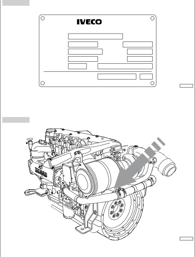
6. IDENTIFICATION DATA
Figure 5
S. p. A.
Viale dell'Industria, 15/17 - 20010 Pregnana Mil.se MI - ITALY
ENGINE TYPE |
|
ENGINE FAMILY |
ENGINE DWG |
POWER (KW) |
POWER SET CODE |
AND SPEED (RPM) |
|
ENGINE S/N |
YEAR OF BUILD |
HOMOLOGATION |
N° |
COMMERC. TYPE / VERSION
04_002_N
Figure 6
04_007_N
The engine identification data are stenciled on a tag positioned over the flywheel case.

MAY 2006 |
INSTALLATIONDIRECTIVE |
N40 ENT M25 |
13 |
|
N60 ENT M37-M40 |
||||
|
|
|
||
|
|
|
|
7. FUEL LINE
Figure 7


 4 3
4 3 


5
2
6


 7 1
7 1


8
High pressure
04_072_N
Low pressure
1.Fuel filter - 2. Common rail - 3. Electro-injector - 4. Electro-injector return loop pressurization valve - 5. Rail overpressure valve -
6.High and low pressure pump - 7. Priming pump - 8. Settling pre-filter.
For the installation, the following connections are required:
-from the tank to the pre-filter
-from the pre-filter to the pump inlet
-from the fuel discharge outlet to the tank
Pre-filter
The pre-filter with priming pump, supplied separately from the engine, must be fastened near the tank, in a relatively low point of the line to allow for easy replacement of the filtering cartridge and/or the operation of the hand pump. Avoid the use of additional mesh or paper filters along the feed lines between pre-filter and engine. To avoid introducing impurities in the feeding lines inside the engine, do not place filter cartridges pre-filled with fuel in the system.
Materials’ Characteristics
The fuel tank and the suction and return assembly must withstand the continuous abrasion caused by a flow of fuel oil of 250 l/h at a temperature of 120 °C without noticeable deformation or wear or release of material. Use of metal tanks, preferably made of iron alloys, is allowed, provided
they are connected to the negative terminal of the battery to prevent the accumulation of electrostatic charges.
Tanks must be provided with vents to avoid exceeding an internal pressure of ± 5kPa (± 0.5 m of H2O column); their shape and the suction assembly must be such as to assure a suction at the maximum longitudinal and transverse inclination allowed for the boat, with a residual quantity of fuel oil considered “reserve”.
The suction inlet should be positioned in such a way as to avoid taking in sludge.The return flow must be in such a way as to facilitate the mixing of the returning fuel with the fuel in the tank. If the tank is lower than the filter, then the return pipe must always be submerged.The pipes and union fittings of the fuel line must withstand a fuel oil flow rate of 250 l/h at a temperature of 120 °C and a pressure of 3 bar (300 kPa) without noticeable deformation, wear or release of material. Metal tubes, preferably made of iron alloys, are recommended, taking care to connect each individual segment to engine ground to avoid the accumulation of electrostatic charges and inserting a vibration damper elastic joint on each segment. The pipes used must be certified according to the relevant Countries’ rules or to the standards issued by classification Bodies.

14 |
N40 ENT M25 |
INSTALLATIONDIRECTIVE |
MAY 2006 |
|
N60 ENT M37-M40 |
||||
|
|
|
||
|
|
|
|
Fuel supply system scheme
Figure 8
2 |
3 |
4 |
5 |
6 |
7 |
8 |
1
19
18
17
16
15
14 |
13 |
12 |
11 |
10 |
9 |
04_040_N
1.High pressure radial pump - 2. Fuel temperature sensor - 3. Fuel filter - 4. Electro-injector - 5. Pressure sensor - 6. Common rail -
7.Common rail overpressure valve - 8. Electro-injector return loop pressurization valve, 1.3 to 2 bar - 9. Fuel tank - 10. Recirculation manifold - 11. Manual priming pump - 12. Pre-filter - 13. Low pressure pump recirculation valve - 14. High and low pressure pump -
15.Low pressure mechanical feed pump - 16. Low pressure pump by-pass valve - 17. Fuel filter support - 18. Low pressure limiter
valve - 19. Pressure regulating electrical valve.
MAY 2006 |
INSTALLATIONDIRECTIVE |
N40 ENT M25 |
15 |
|
N60 ENT M37-M40 |
||||
|
|
|
||
|
|
|
|
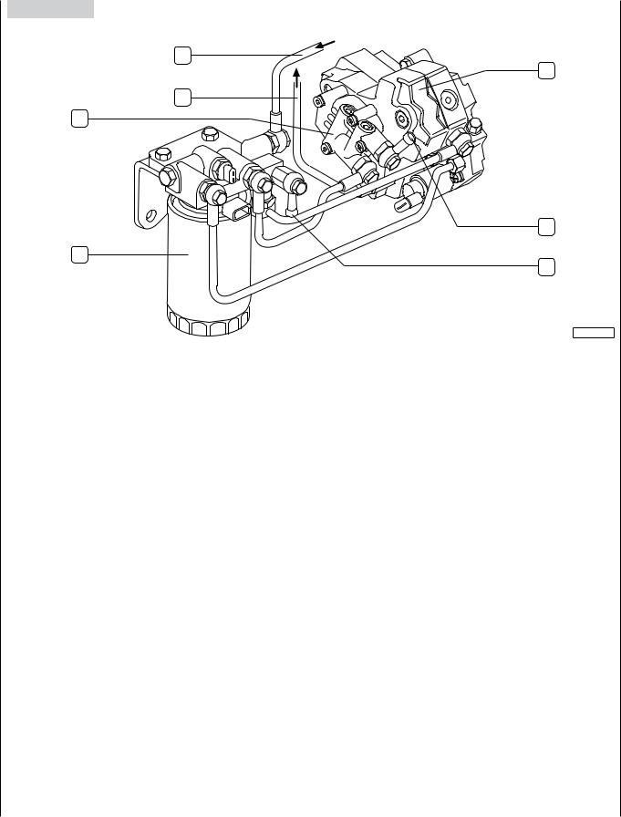
Hydraulic connections
Figure 9
B
2
A
1
3
5
4
04_244_N
A.To rail supply - B. Return flow from rail - 1. Low pressure fuel feed pump - 2. High pressure pump - 3. Rubber holder junction for fuel inflow from pre-filter - 4. Rubber holder junction for fuel outflow to the tank - 5. Fuel filter.
16 |
N40 ENT M25 |
INSTALLATIONDIRECTIVE |
MAY 2006 |
|
N60 ENT M37-M40 |
||||
|
|
|
||
|
|
|
|
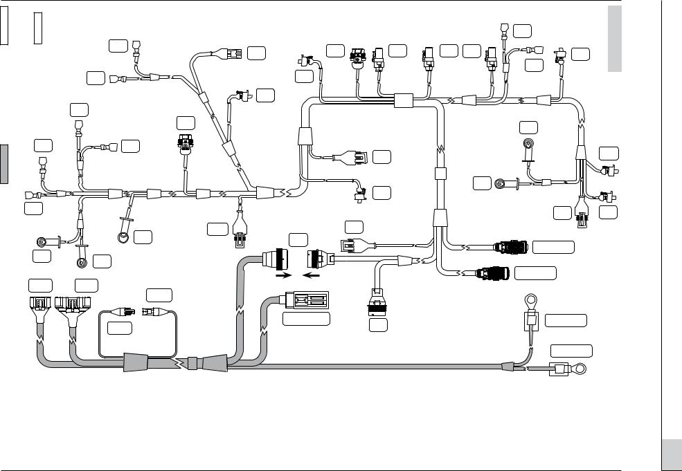
8. ELECTRICAL EQUIPMENT
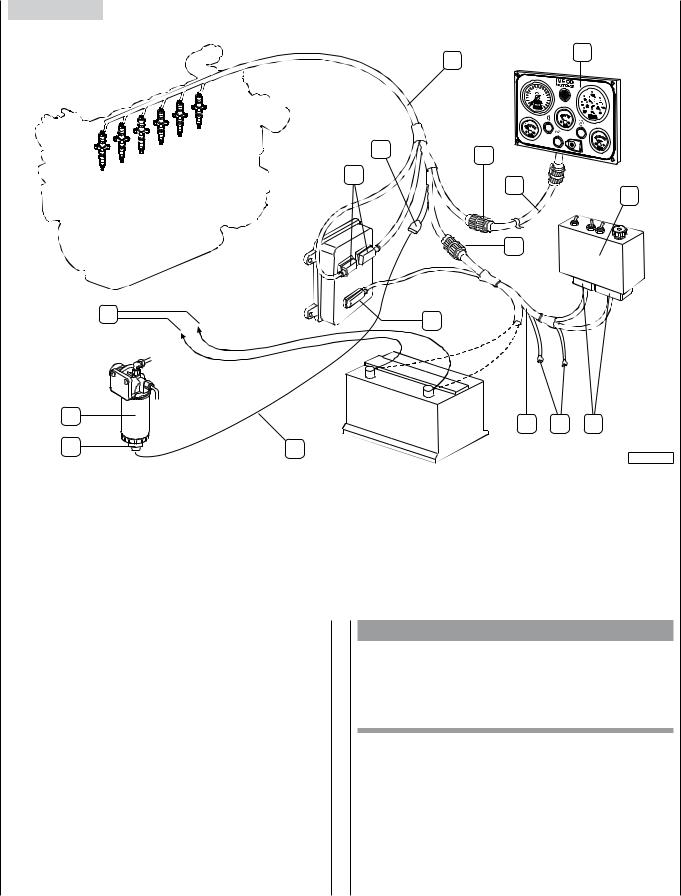
Figure 10
1 |
2 |
|
11 |
4 |
|
10
3
5
6
15 |
9 |
|
14 |
7 |
16 |
8 |
|
|||
13 |
12 |
|
|
05_026_N
1.Engine wiring - 2. Indicator and control panel - 3. Provided wire harness - 4. JB Connection - 5. Relay box - 6. JA Connection -
7.Power supply and interface wire harness - 8. JF1 and JF2 connectors - 9. A2 connector of the ECU - 10. A and A1 connectors of
the ECU - 11. M Connector - 12. Wiring harness to be manufactured by the yard - 13. Sensor for the presence of water in the fuel - 14. Sedimenting pre-filter - 15. Power line for electric starter motor and alternator - 16. ECF and ECM connectors (Present on the wiring of the new model).
The electrical equipment of the engine comprises a series of components provided separately from the engine to enable an easy and diversified installation, according to the Yard’s design choices.The need to make accessible, at sea or underway, the controls to the electrical components and to the connector for diagnostics contained in the relay box may be met through different installation arrangements.
Along with the coupling of all connectors provided in the wire harnesses, completing the installation also requires the connecting wire harness (12) for the sensor for the presence of water in the fuel (13), to complete the power line and to connect the accumulator to the engine wire harness.
To obtain the engine stop if stressed function simply connect the ECF and ECM connectors to each other (these are present on the wiring of the new model).
ATTENZIONE
During the year 2005, some modifications were made to the internal circuits of the relay box and to the wiring. These modifications make incompatible and harmful the use of the components supplied now together with the components supplied before
The following tables show the correct coupling of the components.

MAY 2006 |
INSTALLATIONDIRECTIVE |
N40 ENT M25 |
17 |
|
N60 ENT M37-M40 |
||||
|
|
|
||
|
|
|
|
N40 ENT M25
OLD MODEL
Component |
IVECO |
|
Code |
||
|
||
|
|
|
Engine wiring with clamp |
8039604 |
|
|
|
|
Engine wiring |
8036966 |
|
|
|
|
Interface wiring |
8035938 |
|
|
|
|
12V relay box (brass colour box) |
8035890 |
|
|
|
|
24V relay box (brass colour box) |
8035891 |
|
|
|
|
EXISTING MODEL |
|
|
Component |
IVECO |
|
Code |
||
|
||
|
|
|
Engine wiring with clamp |
8041500 |
|
|
|
|
Engine wiring |
8041167 |
|
|
|
|
Interface wiring |
8041169 |
|
|
|
|
12V relay box (brass colour box) s |
8041257 |
|
|
|
|
12V relay box (black colour box) s |
8042960 |
|
|
|
|
24V relay box (brass colour box) * |
8041353 |
|
|
|
|
24V relay box (black colour box) * |
8042040 |
|
|
|
s Interexchangeable
* Interexchangeable
Chapter 24 shows the electric schemes of the tow models which in the table titles are shown as “OLD MODEL” and “EXISTING MODEL”.
N60 ENT M37-M40
OLD MODEL
Component |
IVECO |
|
Code |
||
|
||
|
|
|
Engine wiring with clamp |
8035822 |
|
|
|
|
Engine wiring |
8035817 |
|
|
|
|
Interface wiring |
8035938 |
|
|
|
|
12V relay box (brass colour box) |
8035890 |
|
|
|
|
24V relay box (brass colour box) |
8035891 |
|
|
|
|
EXISTING MODEL |
|
|
Component |
IVECO |
|
Code |
||
|
||
|
|
|
Engine wiring with clamp |
8041170 |
|
|
|
|
Engine wiring |
8041168 |
|
|
|
|
Interface wiring |
8041169 |
|
|
|
|
12V relay box (brass colour box) s |
8041257 |
|
|
|
|
12V relay box (black colour box) s |
8042960 |
|
|
|
|
24V relay box (brass colour box) * |
8041353 |
|
|
|
|
24V relay box (black colour box) * |
8042040 |
|
|
|
s Interexchangeable
* Interexchangeable
Chapter 24 shows the electric schemes of the tow models which in the table titles are shown as “OLD MODEL” and “EXISTING MODEL”.
18 |
|
N40 ENT M25 |
|
INSTALLATIONDIRECTIVE |
MAY 2006 |
|||
|
N60 ENT M37-M40 |
|
||||||
|
|
|
|
|
|
|
||
|
|
|
|
|
|
|
|
|
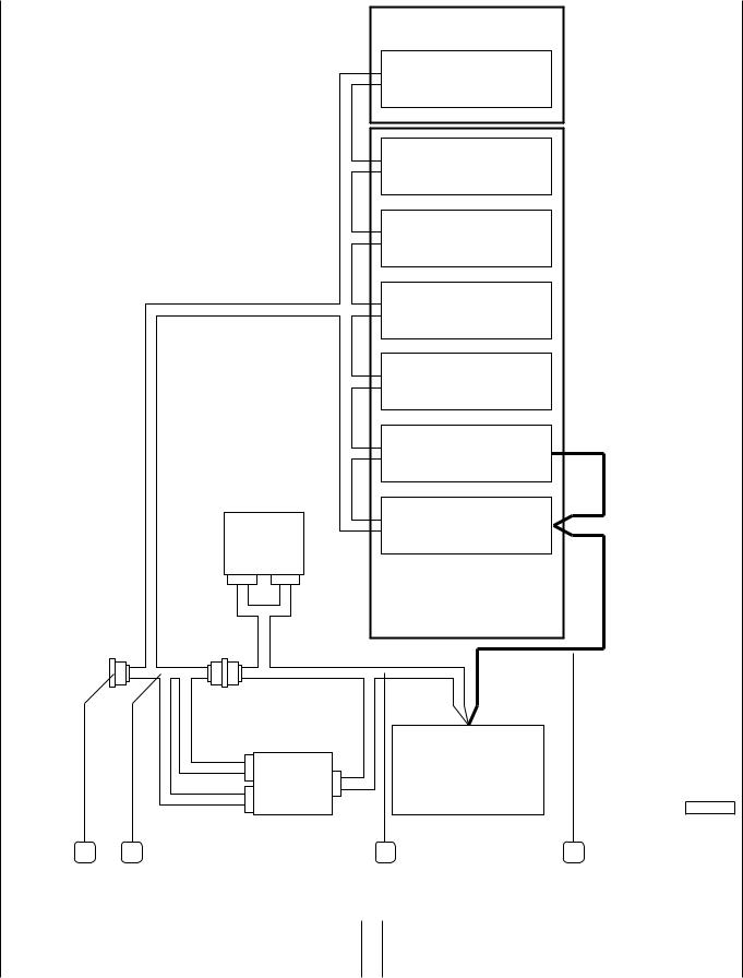
Synoptic |
|
|
|
|
||||
|
|
|
|
|
|
|
||
|
|
Figure 11 |
|
|
|
Gear box |
|
|
|
|
|
|
|
|
|
|
|
|
|
|
|
|
|
|
Indications and |
|
|
|
|
|
|
|
|
alarms sensors |
|
|
|
|
|
|
|
|
Throttle position |
|
|
|
|
|
|
|
|
sensor |
|
|
|
|
|
|
|
|
Indications and |
|
|
|
|
|
|
|
|
alarms sensors |
|
|
|
|
|
|
|
|
Electro-injectors |
|
|
|
|
|
|
|
|
EDC components |
|
|
|
|
|
|
|
|
Alternator |
|
|
|
|
|
|
|
|
Electric starter |
|
|
|
|
|
|
Relay |
|
motor |
|
|
|
|
|
|
box |
|
N40 ENT M25 |
|
|
|
|
|
|
|
|
|
|
|
|
|
|
|
JF1 |
JF2 |
N60 ENT M37 |
|
|
|
|
|
|
|
|
||
|
|
|
|
|
|
|
N60 ENT M40 |
|
|
|
|
JB |
JA |
|
|
|
|
|
|
A |
Battery |
|
|
EDC |
|
|
|
|
|
|
|
A2 |
04_235_N |
|
|
A1 |
|
1 |
2 |
3 |
4 |
1. Connector for instrument panel connection wire harness - 2. Engine wire harness - 3. Interface wire harness - 4. Power line.
The wire harnesses provided with the engine include the connectors for all optional components which may ordered and their connections to the JB connector for the indicator and control panel.
harness wire Engine
harness wire Interface
N_025_05
SI
SI
VI
JF2
(*) Not applicable for the 4 cylinders |
s Present on the wiring of the new model (See Chapter 8) |
|||
T |
O |
H |
E1 |
E2 E3 |
|
||||
T |
|
PR |
|
(*) |
F
WI
VE |
|
|
WI |
|
|
|
|
PA |
|
|
V |
|
|
B |
GG |
|
M |
MM |
JA |
|
VI |
|
|
JF1 |
|
|
ECM s |
|
|
ECF s |
A2 EDC |
JB |
|
K
C
K
V
PF
A EDC
A1 EDC
+ BATT
– BATT
12 Figure
ZH
A
A. Fuel temperature sensor for EDC - B. Drive shaft sensor for EDC - C. Camshaft sensor - F. Engine coolant temperature sensor for EDC - ECF. Connector for the engine stopping functions if stressed - ECM. Connector for the engine stopping function if stressed - H. Combustion air pressure/temperature sensor for EDC - K. Air filter clogging sensor (for alarm) - M. Sensor for detecting the presence of water in the fuel pre-filter (for alarm) - O. Exhaust gas temperature sensor (for gauge) - T. Coolant temperature sensor (for gauge) - V. Oil pressure sensor (for gauge) - E1. Cylinders 1 and 2 electro-injectors - E2. Cylinders 3 and 4 electro-injectors - E3. Cylinders 5 and 6 electro-injectors -
GG. Alternator - JB. Instrument panel connection wire harness - JF1,JF2. Relay box - MM. Electric starter motor - PA. Throttle position sensor - PF. Heating element on fuel filter - PR. Rail pressure sensor - SI. Gear box oil temperature sensor - VE. Engine oil pressure/temperature sensor for EDC - VI. High gear box oil pressure sensor (25 bar) -
WI. Low gear box oil pressure sensor (7 bar) - ZH. Pressure control solenoid valve.
harness Wire |
2006 MAY |
DIRECTIVEINSTALLATION
M25 ENT N40
19 M40-M37 ENT N60
20 |
N40 ENT M25 |
INSTALLATIONDIRECTIVE |
MAY 2006 |
|
N60 ENT M37-M40 |
||||
|
|
|
||
|
|
|
|
Power supply line |
|
|
|
Figure 13 |
|
|
|
|
|
|
4 |
Equipment power supply |
|
||
2 |
|
|
|
30 |
50 |
+B |
D+ |
M |
|
|
|
05_004_N
1 |
3 |
1.Alternator - 2. Electric starter motor - 3. Battery - 4. Engine wire harness.
The connection of the +B terminal of the alternator to the positive +30 terminal of the electric starter motor must be achieved with a conductor having a cross section of at least 10 mm2.The connection of the positive +30 terminal of the electric starter motor to the positive pole of the battery, achieved with a conductor having a cross section of at least 70 mm2, allows to obtain, as shown in the figure, the simultaneous connection of the alternator to the battery.The connection between the engine ground and the negative pole of the battery must be achieved according to the guidelines provided in the Engine electrical ground paragraph.
CAUTION
If magneto-thermal protecting breakers are inserted, they must not be used to stop the engine and in any case they must be activated only a few seconds after shut-down.
Supplementary services battery
To assure that the engine can be started with a sufficient quantity of energy, it is advisable to provide for the installation of a supplementary battery, dedicated to supplying power to the on-board electrical services.The power line to recharge it may be constructed according to the indications provided in Chapter 24.
If one engine is installed
The battery used for services may be recharged interposing on the power supply line a relay actuated by the recharge signal of the alternator’s electronic regulator (D+).
If two engines are installed
The presence of two generators allows to keep the recharging functions separated: the generator (G1) recharges the battery (AC1) dedicated to starting both engines and powering both electrical/electronic control circuits, whilst the generator (G2) recharges the battery (AC2) used to power the services. In two-engine applications, it is essential to connect the engine grounds to a common potential; the solution proposed in Chapter 24 fully complies with this need, assuring the full functionality and independence of the two circuits.
MAY 2006 |
INSTALLATIONDIRECTIVE |
N40 ENT M25 |
21 |
|
N60 ENT M37-M40 |
||||
|
|
|
||
|
|
|
|
Engine electrical ground
The connection of the engine electrical ground is achieved by connecting with a cable of at least 70 mm2 cross section to the negative pole of the battery to the tightening point of the electric starter motor as shown in Figure 14.
Figure 14
1
04_077_N
1. Point of connection of the engine electrical ground.
To anchor the grounding terminal to the engine, proceed as follows:
Completely remove the conducting paint from both parts constituting the connection, using mechanical means or suitable chemical product; if the anchoring operation is to take place on superficially treated parts, completely remove the anaphoretic paint with mechanical means, obtaining a smooth support surface.
Apply a uniform layer of BH44D paint (IVECO standard 181705) with a brush or spray gun.
Join the parts constituting the grounding note within 5 minutes from the time the paint was applied.
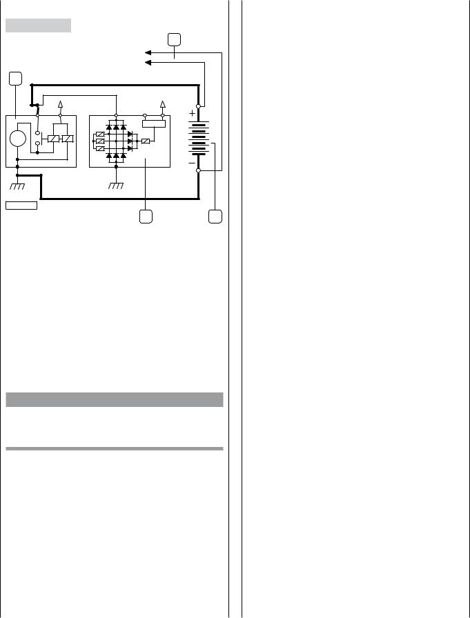
Battery recharging
Figure 15
04_078_N
B+. Connected to the +30 of the electric starter motor - D+. Excitation - N. Not connected.
This is accomplished through the power supply line of the electric starter motor and connection to the +B of the alternator. The electronic regulator of the alternator that equips the engine allows an effective control over the battery recharging operation.
If, due to installation requirements, the batteries need to be positioned at a distance from the engine, we recommend increasing the cross section of the power line conductors and verifying recharging effectiveness by measuring voltage across the battery poles.
 Loading...