


GEARBOX EuroTronic 12 AS 2301 D.D.

GEARBOX EuroTronic 12 AS 2301 D.D./O.D.
113
STRALIS AT/AD
Print 603.93.141 Base - January 2003
Gearbox
EuroTronic 12 AS 2301 D.D./O.D.
Page
DESCRIPTION 115. . . . . . . . . . . . . . . . . . . . . . . . . .
SPECIFICATIONS AND DATA 116. . . . . . . . . . . . .
TIGHTENING TORQUES 119. . . . . . . . . . . . . . . . .
TOOLS 120. . . . . . . . . . . . . . . . . . . . . . . . . . . . . . . .
OVERHAULING THE GEARBOX 125. . . . . . . . . . .
- Checks 125. . . . . . . . . . . . . . . . . . . . . . . . . . . . . .
- Gearbox actuator 125. . . . . . . . . . . . . . . . . . . . . .
- Removal 125. . . . . . . . . . . . . . . . . . . . . . . . . . . . .
- Refitting 126. . . . . . . . . . . . . . . . . . . . . . . . . . . . . .
- Removing the rear box 126. . . . . . . . . . . . . . . . . .
- Removing the rear box 127. . . . . . . . . . . . . . . . . .
- Removing the epicyclic reduction
gear train (E.R.G.) 128. . . . . . . . . . . . . . . . . . . . . .
- Fitting the epicyclic reduction gear train (E.R.G.) 130
- Adjusting epicyclic reduction gear train bearing
end float 131. . . . . . . . . . . . . . . . . . . . . . . . . . . . .
- Adjusting main shaft end float 132. . . . . . . . . . . . .
- Synchronizing device assembly for engaging
normal or reduced gears 134. . . . . . . . . . . . . . . . .
- Removal 134. . . . . . . . . . . . . . . . . . . . . . . . . . . . .
- Fitting 134. . . . . . . . . . . . . . . . . . . . . . . . . . . . . . .
- Removing the middle box 137. . . . . . . . . . . . . . . .
- Removing the main shaft 139. . . . . . . . . . . . . . . . .
- Removing the drive input shaft 141. . . . . . . . . . . .
- Removing the splitter synchronizing device 142. . .
- Fitting the splitter synchronizing device 143. . . . . .
- Fitting the drive input shaft 144. . . . . . . . . . . . . . .

114
GEARBOX EuroTronic 12 AS 2301 D.D./O.D.
STRALIS AT/AD
Base - January 2003 Print 603.93.141
Page
- Fitting the main shaft 144. . . . . . . . . . . . . . . . . . . .
- Splitter control fork 147. . . . . . . . . . . . . . . . . . . .
- Disassembly - Assembly 147. . . . . . . . . . . . . . . . .
- Gear control forks 147. . . . . . . . . . . . . . . . . . . . .
- Removal 147. . . . . . . . . . . . . . . . . . . . . . . . . . . . .
- Fitting 148. . . . . . . . . . . . . . . . . . . . . . . . . . . . . . .
- Transmission shafts 149. . . . . . . . . . . . . . . . . . . . .
- Disassembly - Assembly 149. . . . . . . . . . . . . . . . .
- Fitting the middle box 149. . . . . . . . . . . . . . . . . . .
- Fitting the front box 152. . . . . . . . . . . . . . . . . . . .
- Front cover 154. . . . . . . . . . . . . . . . . . . . . . . . . . .
- Removal 154. . . . . . . . . . . . . . . . . . . . . . . . . . . . .
- Fitting the front cover 154. . . . . . . . . . . . . . . . . . .
- Adjusting drive input shaft bearing end float 154. .
- Adjusting transmission shaft bearing end float 155
- Clutch release lever 157. . . . . . . . . . . . . . . . . . . .
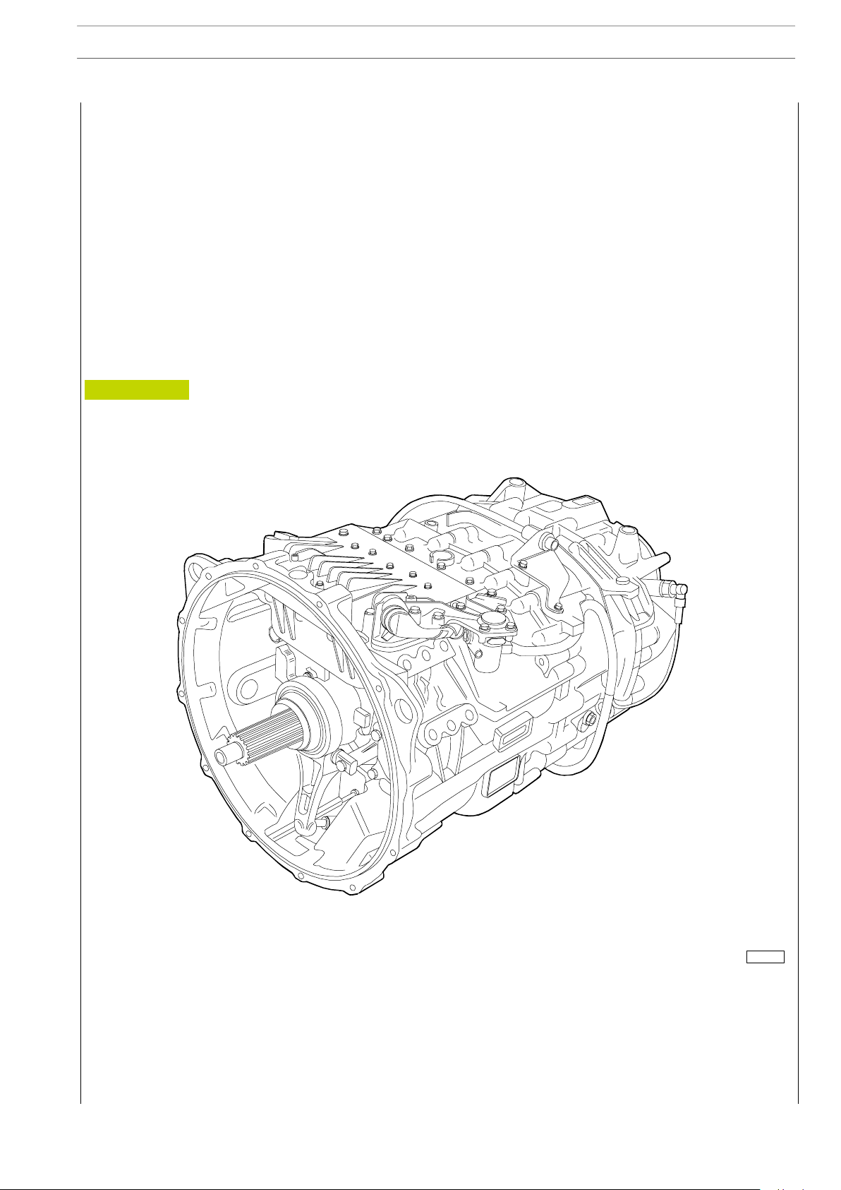
DESCRIPTION
The EuroTronic gearbox 12 AS 2301 D.D./O.D. is mechanical with electro-pneumatic control.
The driver can choose whether to program gear selection/engagement manually or automatically. The shafts and gears have
helical toothing that reduces operating noise.
The main shaft gear coupling is obtained with sleeves with front toothing.
The splitter and epicyclic reduction gear unit engagement is synchronized.
The speeds are selected with finely staggered ratios and can be engaged in succession with the coupling of the epicyclic reduction
gear unit ”ERG” and the ”Splitter” slow or fast speed unit.
On engaging the ”ERG”, the speeds of the main shaft are doubled. The ratios obtained in this way are further doubled with the
engagement of the ”Splitter”. Each single ratio is thus divided into a fast or slow ratio.
D.D. = Direct drive
O.D. = Over Drive (Multiplied)
Figure 1
000418 t
GEARBOX EuroTronic 12 AS 2301 D.D./O.D.
115
STRALIS AT/AD
Print 603.93.141 Base - January 2003
116
GEARBOX EuroTronic 12 AS 2301 D.D./O.D.
STRALIS AT/AD
Base - January 2003 Print 603.93.141
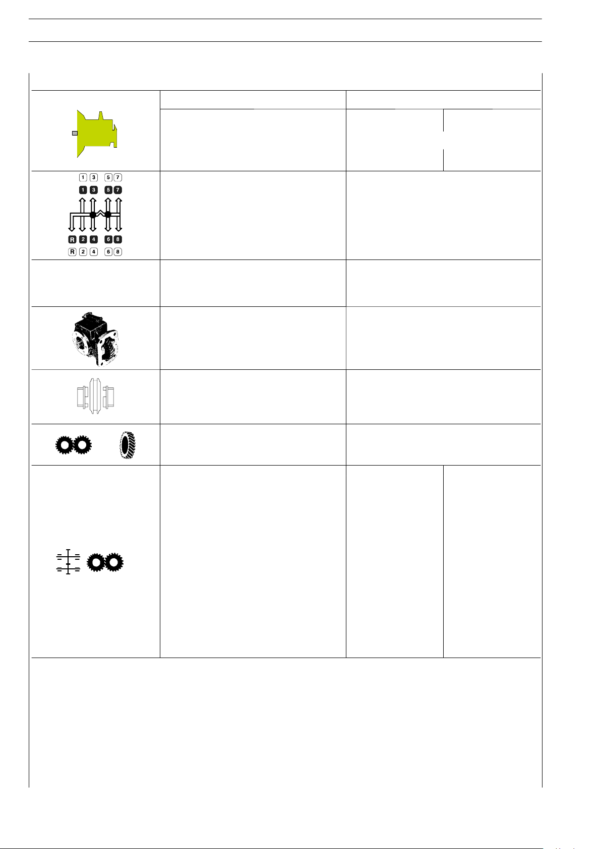
SPECIFICATIONS AND DATA
GEARBOXES EuroTronic Automated
12 AS 2301 D.D. 12 AS 2301 O.D.
Type Mechanical
Torque activated Nm
1900 2500
Forward gears
Reverse gears
12
2
Type of running control electronically-operated semi-automatic
Rear power takeoff optional
Gear engagement:
E.R.U.* and splitter engagement
by front engagement sleeves
free ring synchroniser
Gears constantly engaged straight toothed
Gear ratios
1
a
2
a
3
a
4
a
5
a
6
a
7
a
8
a
9
a
10
a
11
a
12
a
1aRM
2
a
RM
15.85
12.32
9.56
7.43
5.87
4.56
3.47
2.70
2.09
1.62
1.28
1.00
14.68
11.41
12.33
9.59
7.44
5.78
4.57
3.55
2.70
2.10
1.63
1.27
1.00
0.78
11.41
8.88
ERG* = Epicyclic Reduction Gearing
D.D. = Direct drive
O.D. = Over Drive (Multiplied)
GEARBOX EuroTronic 12 AS 2301 D.D./O.D.
117
STRALIS AT/AD
Print 603.93.141 Base - January 2003
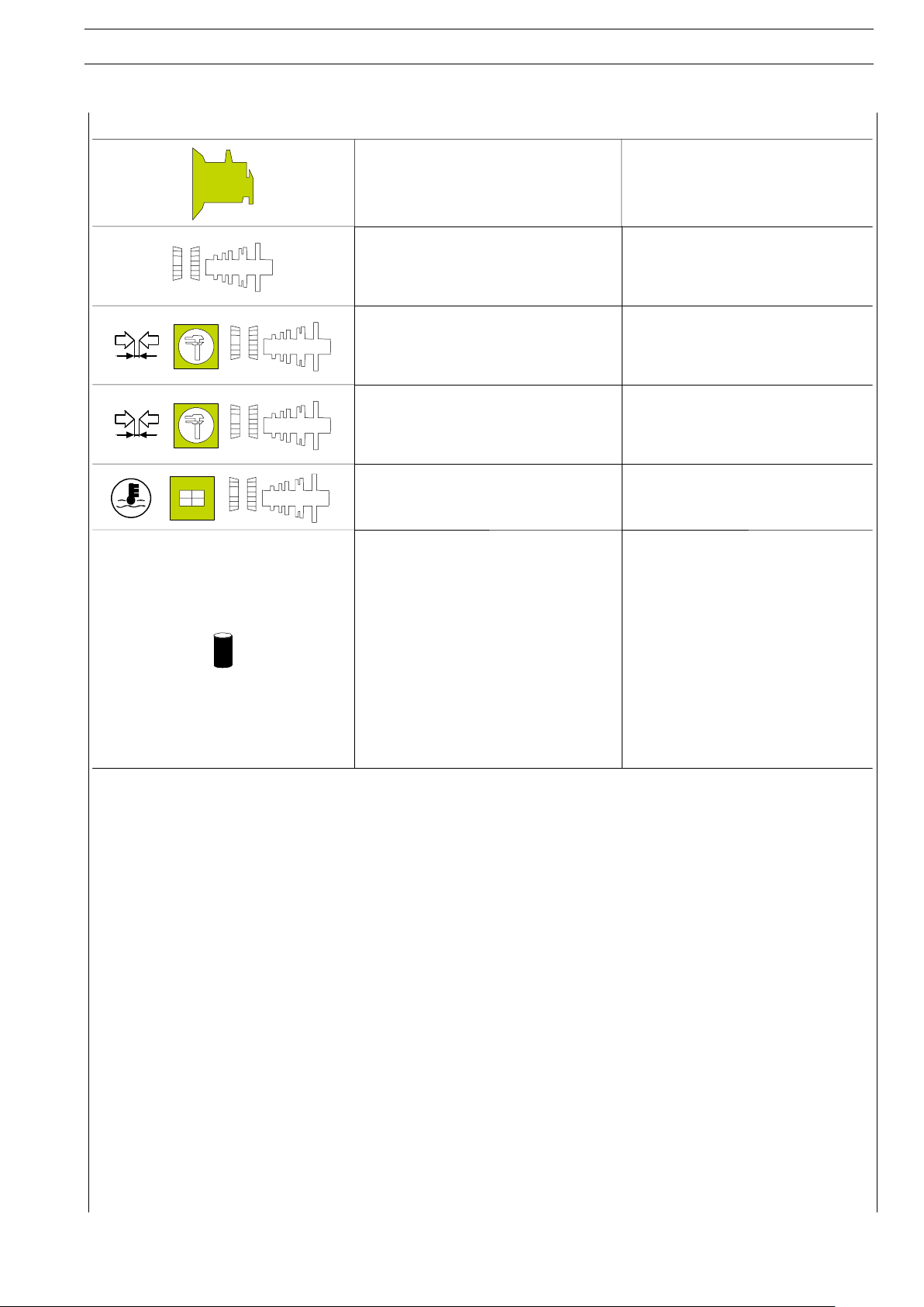
SPECIFICATIONS AND DATA
EuroTronic Automated
12 AS 2301 D.D./O.D.
Bearings
- drive input shaft
- ERG* shaft
- transmission shafts
with balls
with cylindrical rollers
with tapered rollers
Bearing end float:
- drive input shaft
- ERG* planet shaft
- transmission shafts
0 y 0.1 mm
0 y 0.1 mm
- 0.05 y + 0.05 mm
End float:
- main shaft
- drive input shaft split ring
0.2 mm
0 y 0.1 mm
Temperature for fitting bearings or bearing
seats on the boxes
120 qC
Forced lubrication with positive displacement pump flow rate (with 12
th
speed en-
gaged and oil at a temperature of 80ºC)
pressure with 12thspeed engaged at 2400
rpm and oil at a temperature of:
40ºC
80ºC
50 dm3/min
1.7 bar
1.2 bar
Oil type
litres
kg
Tutela Truck Fe-Gear
Tutela ZC 90
12
11
ERG* = Epicyclic Reduction Gearing
D.D. = Direct drive
O.D. = Over Drive (Multiplied)
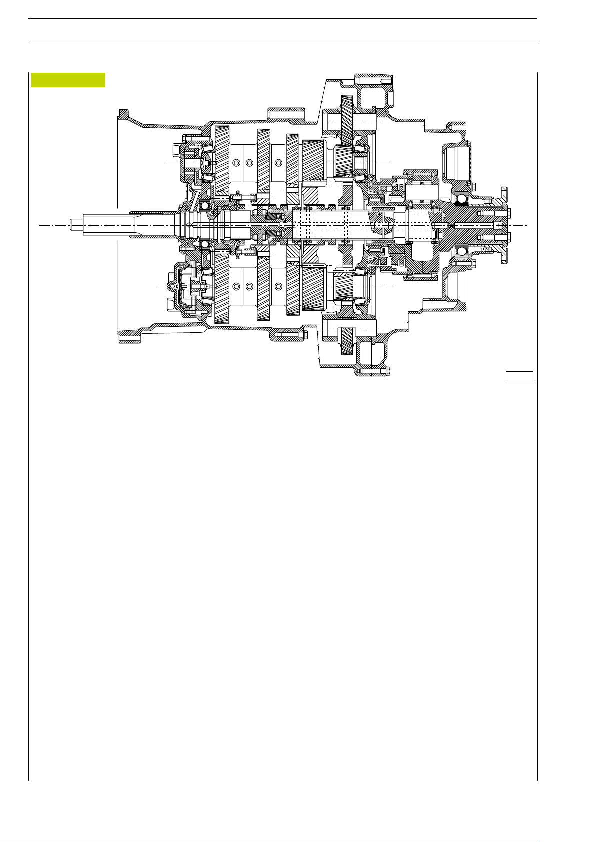
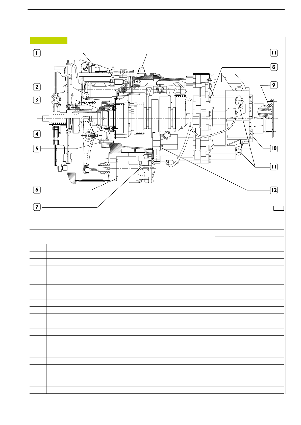
Figure 2
LONGITUDINAL CROSS-SECTION OF EUROTRONIC 12AS 2301 GEARBOX
001396 t
118
GEARBOX EuroTronic 12 AS 2301 D.D./O.D.
STRALIS AT/AD
Base - January 2003 Print 603.93.141
GEARBOX EuroTronic 12 AS 2301 D.D./O.D. 119
STRALIS AT/AD
Print 603.93.141 Base - January 2003
TIGHTENING TORQUES
TORQUE
DESCRIPTION
Nm kgm
1 Screws fixing gearbox actuator 23 2.3
2 Screw fixing oil pump 10 1
3 Screws fixing drive input shaft cover 23 2.3
4
Screw fixing clutch uncoupling lever control pin:
- M 12 8.8
- M 12 10.9
79
115
7.9
11.5
5 Screws fixing cover (spread LOCTITE 241 on the thread) 79 7.9
6 Screws fixing clutch actuator 23 2.3
7 Screw cap to discharge air from clutch actuator 22 2.2
8 Screws fixing rear box to middle box 46 4.6
9 Screws fixing flange retaining plate 120 12
10 Screws fixing rear cover 5 4.6
11 Speed sensor 45 4.5
12 Screws fixing middle box to front box 50 5
Pin on rod (spread LOCTITE 262 on the thread) 23 2.3
Oil vapour vent 10 1
Screw plug M 10x1 on rear box 15 1.5
Screw plug M 24x1 on rear box 60 6
Screw M12 fixing power take-off bay cover 79 7.9
Screw plug M 24x1.5 on middle box 60 6
Screw fixing plates retaining fork joint pins on rear box 23 2.3
70824
Figure 3
120
GEARBOX EuroTronic 12 AS 2301 D.D./O.D.
STRALIS AT/AD
Base - January 2003 Print 603.93.141
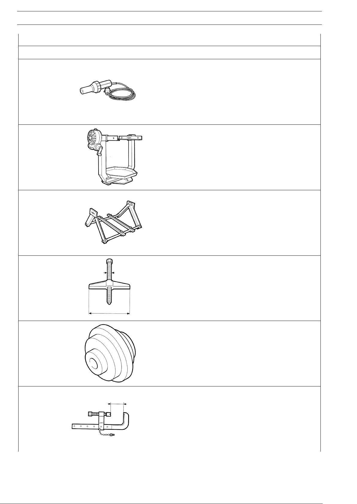
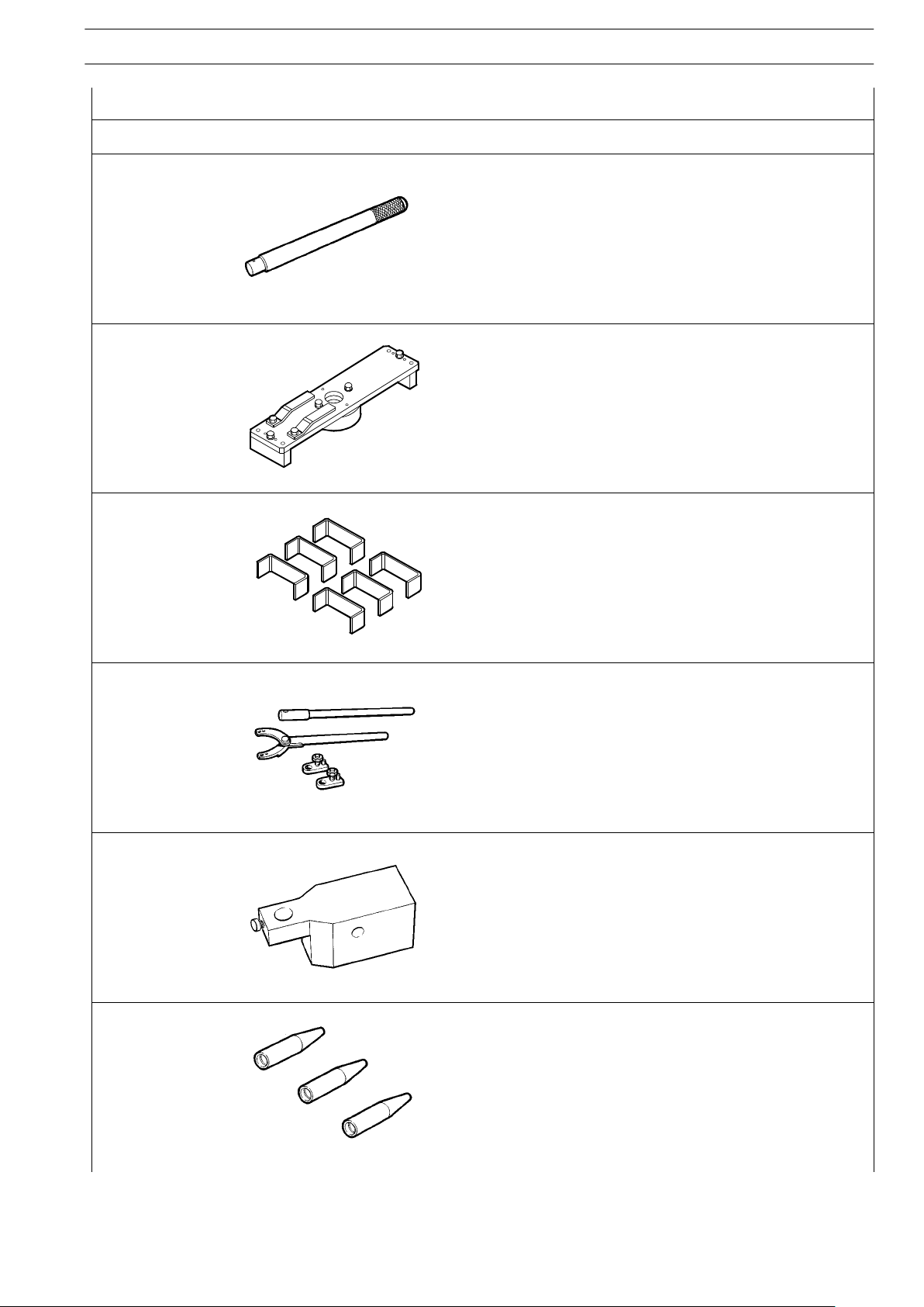
TOOLS
TOOL NO. DESCRIPTION
Hot air device
99305121
99322205
Rotary stand for overhauling assemblies
99322225
Mount to support assemblies (to fit onto stand 99322205)
99341003
Single-acting bridge
99341013
Reaction block
99341015
Clamp
GEARBOX EuroTronic 12 AS 2301 D.D./O.D. 121
STRALIS AT/AD
Print 603.93.141 Base - January 2003
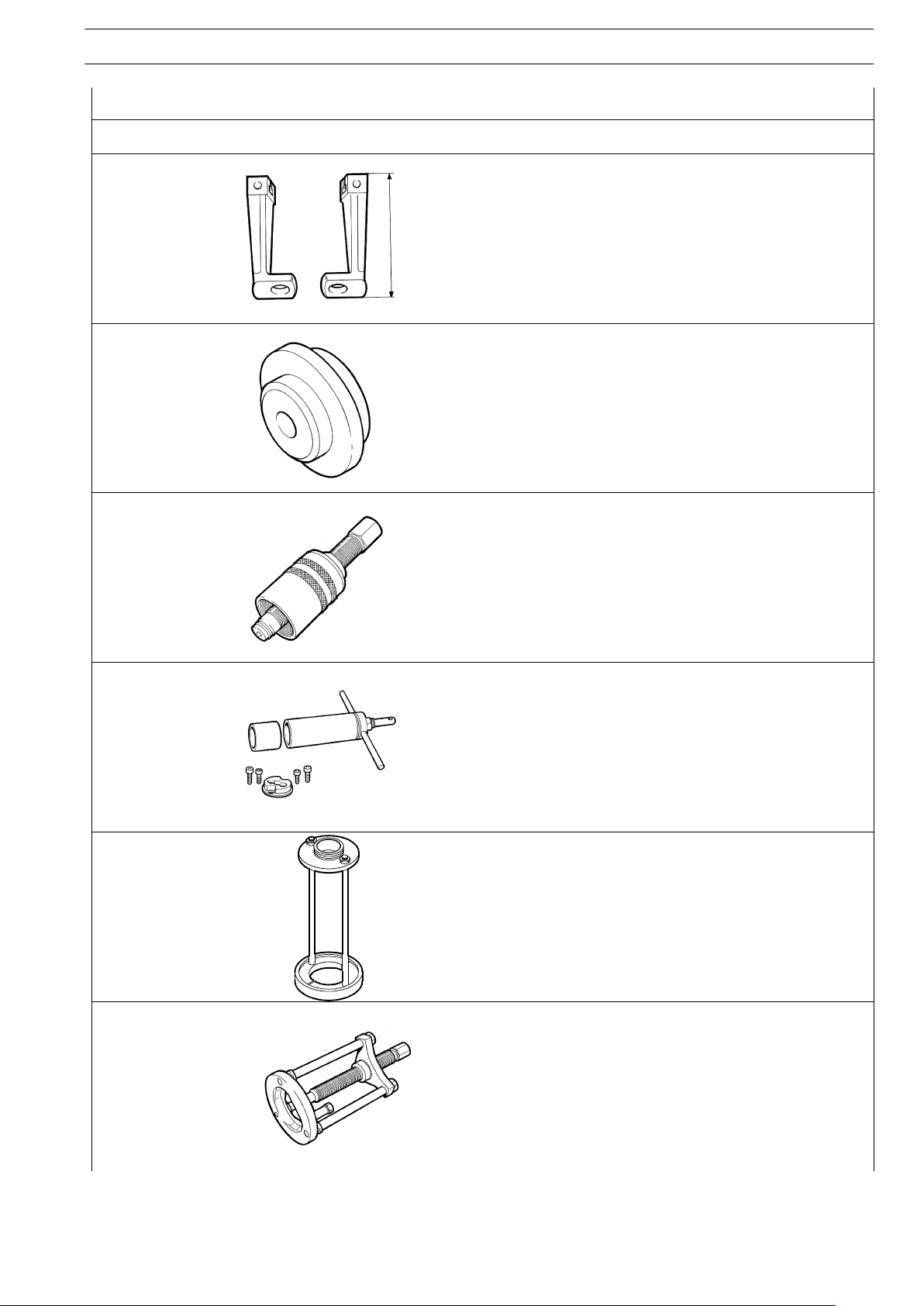
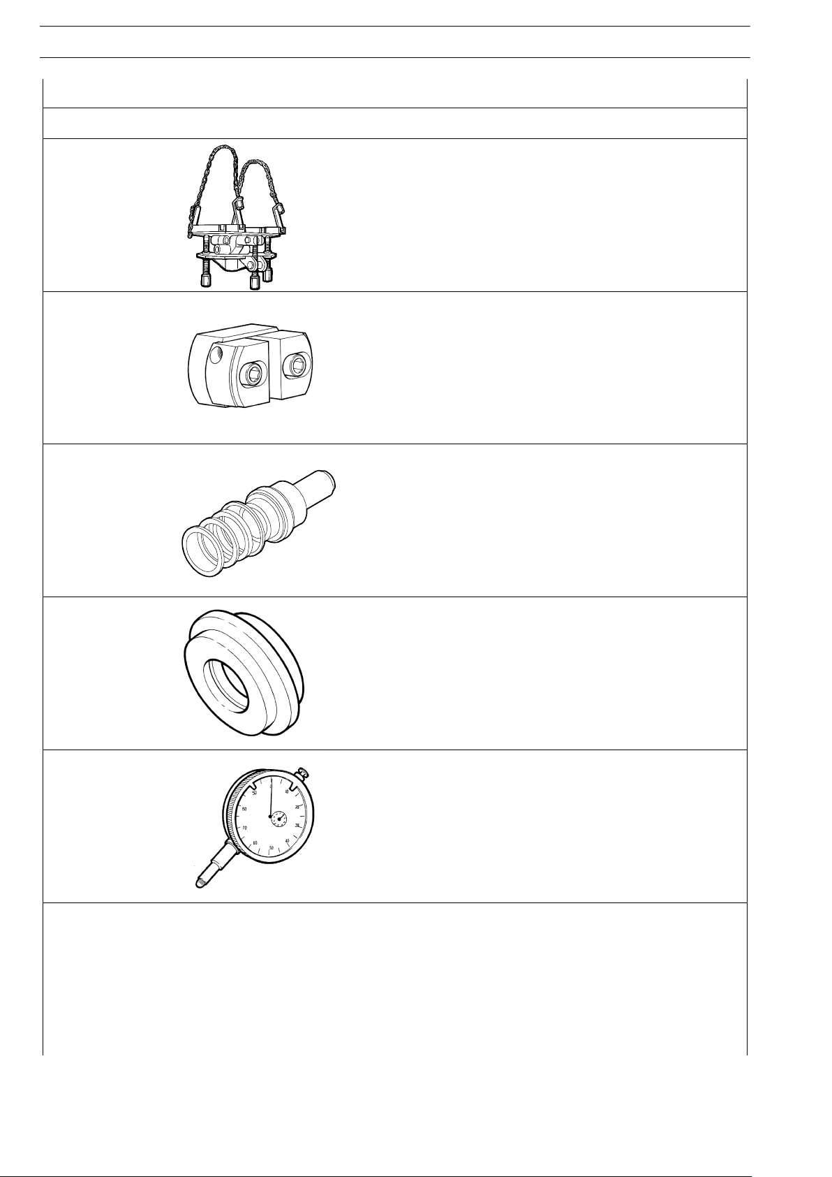
TOOLS
TOOL NO. DESCRIPTION
99341018
Pair of brackets with hole
99345057
Extractor reaction block
99345078
Extractor to remove drive input shaft bearing (use with 99345105)
993450998
Inserter to fit bearing on main shaft, rear side and to insert rear flange
of gearbox
99345105
Extractor for gearbox drive input shaft bearing (use with 99345078)
99347100
Small extractor (use with specific rings with 99347132)
122
GEARBOX EuroTronic 12 AS 2301 D.D./O.D.
STRALIS AT/AD
Base - January 2003 Print 603.93.141
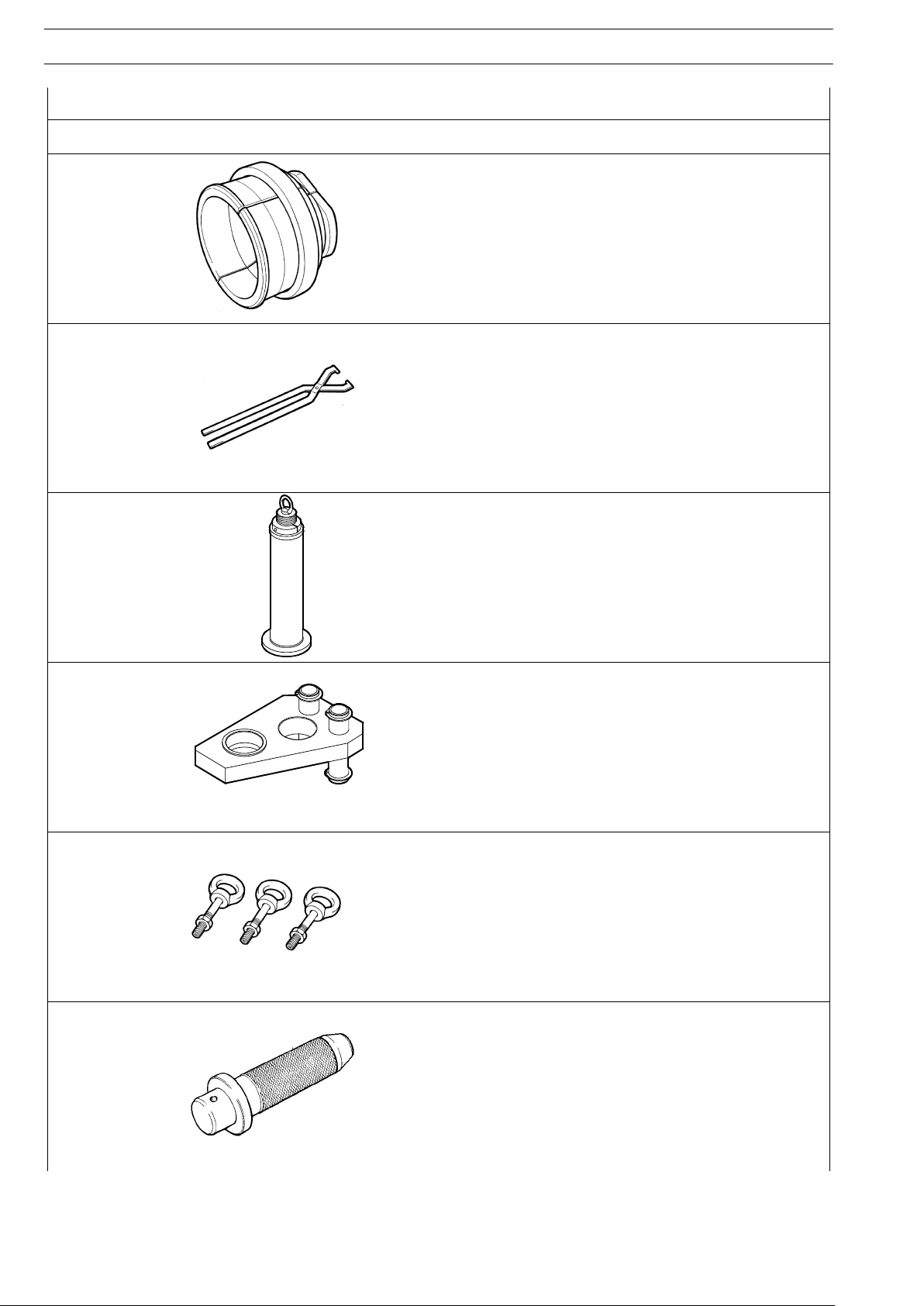
TOOLS
TOOL NO. DESCRIPTION
99347132
Ring grips to extract gearbox transmission shaft bearings (use with
99345057 - 99347100)
99360323
Tool to turn drive input shaft when refitting the gearbox to the
engine
99360526
Tool to extract and insert main shaft (use with 99360527) and to
drive in gearbox drive input shaft bearing (use with 99345098)
99360527
Tool retaining gearbox main shaft forks (use with 99360526)
99366811
Set of M10 eyebolts (3) to remove and refit gearboxes
99370006
Grip for interchangeable drifts
GEARBOX EuroTronic 12 AS 2301 D.D./O.D. 123
STRALIS AT/AD
Print 603.93.141 Base - January 2003
TOOLS
TOOL NO. DESCRIPTION
99370007
Grip for interchangeable drifts
99370153
Tool for positioning main shaft when removing the transmission
shafts and for retaining gearbox reverse gear pins
99370172
Tools (6) to mount gearbox epicyclic reduction gear train
synchronizer rings
99370317
Reaction lever with extension to fasten drive output flange
99370415
Dial gauge base to adjust transmission shaft bearings (use with
99395604)
99370499
Guides (no. 3) to mount Splitter synchronizing device assembly
124
GEARBOX EuroTronic 12 AS 2301 D.D./O.D.
STRALIS AT/AD
Base - January 2003 Print 603.93.141
TOOLS
TOOL NO. DESCRIPTION
99370629
Mount to support gearbox when removing and fitting it back on the
vehicle
99374092
Drift to mount outer races of bearings (69 y 91) (use with
99370007)
99374221
Driver to mount seals on back cover
99374336
Driver to fit seals on the front cover of the gearbox (use with
99370006)
99395604
Dial gauge (0 - 10 mm)

Figure 4
Checks
The gears, synchronizer rings, coupling bodies and sliding
couplings must show no sign of failure or excessive toothing
wear.
The main shaft must have no indentation, especially on the
sliding surfaces of the gear rotation and coupling sleeves.
The reverse idle gear shafts must have a polished surface free
from scoring.
The gearboxes must show no sign of cracking and the bearing
seats must be neither damaged nor worn, so as to prevent the
outer rings of the bearings from turning in their seats.
Check the shoulder spacers are neither worn nor damaged.
The gear coupling forks must show no sign of cracking and the
relevant control rods must slide freely, but without any
appreciable play, in their guide seats.
Check that the shoes of the drive forks are fully efficient.
Check that the holes, grooves and lubrication pipes are not
obstructed by grease or foreign bodies.
Check the bearings are not worn, damaged or overheated.
530210 OVERHAULING THE
GEARBOX
!
Wash the assembly thoroughly before overhauling.
The specific and/or general tools must be used in the
way for which they were designed.
To facilitate assembly, put the removed parts away on
the specific tray in their order of removal.
Upon assembly, the following must always be
replaced with new parts: the gaskets and seals, spring
pins, safety plates and springs. Nuts and screws must
be tightened to the prescribed torque with their
thread dry and degreased.
Keep to the specific regulations when disposing of
lubricant and detergents.
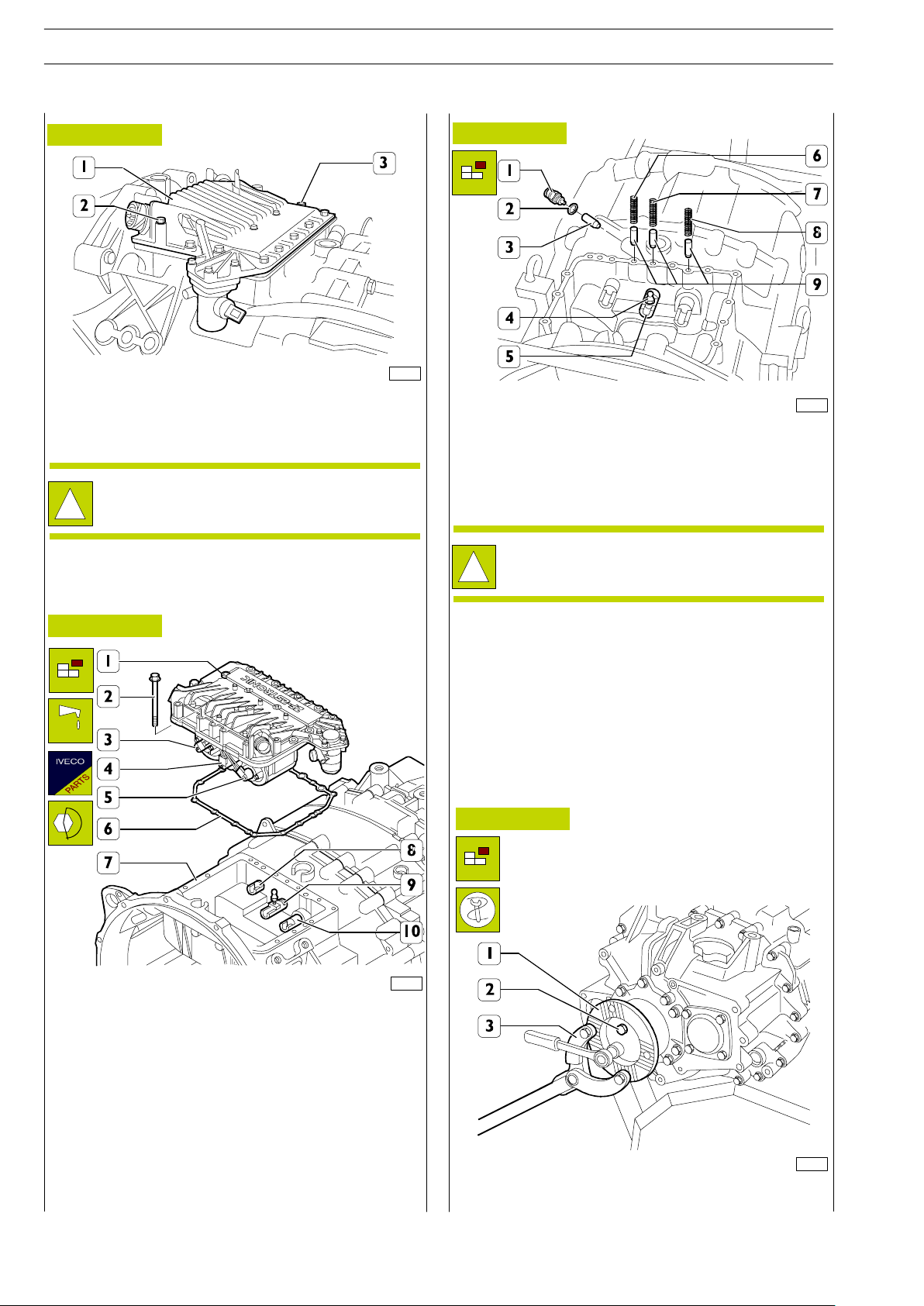
530520 Gearbox actuator
Removal
Unscrew the ring nut (1 and 5) and disconnect the electric
wiring (2) from the speed sensor (6 and 7).
Detach the wiring (2) from the clips (o) securing it to the
middle box.
Remove the nuts (4) and detach the actuator (3) from the
front box.
Figure 5
78649
78650
Fasten the gearbox (1) to brackets 99322225 (3) on the
rotating stand 99322205 (2).
Remove the plug and bleed the lubrication oil.
The following described and illustrated overhaul
operations regard transmission 16 A6 2601 and, save
different indications, are valid also for transmission 12
AS 2301.
!
GEARBOX EuroTronic 12 AS 2301 D.D./O.D. 125
STRALIS AT/AD
Print 603.93.141 Base - January 2003
70828
70863
70830
Figure 6
Figure 7
Figure 8
Figure 9
Set a new gasket (6) on the front case (7).
Lubricate the stems of the solenoid valves (3-4-5) with silicone
grease and put them into a neutral position. Put the rods
(8-9-10) into a neutral position. Fit the actuator (1) on the
front box (7) verifying thatthe end of the stems of the solenoid
valves is correctly positioned in the seats of the rods (8-9-10).
Tighten the fixing screws (2) to the prescribed torque. After
removing the gearbox from the stand used for overhaul, refit
the clutch actuator (3, Figure 4) and make sure the wiring (2,
Figure 4) is not damaged.
Extract the springs (6-7-8) and the pawls (6).
Block rotation of the sleeve (1) by applying the lever
99370317 (3) and slightly loosen the screws (2).
!
The springs (7 and 8) are of equal length, the spring
(6) is larger.
Remove the pin (4) from the rod (5).
Remove the switch (1) together with the gasket (2) and
extract the cap (3).
78651
Take out the screws (2) and detach the actuator (1) with its
gasket.
!
The electronic control unit is integrated in the
actuator and these cannot be overhauled. See under
the diagnosis heading for the check.
Check that the oil vapour vent (3) is not clogged; if it is, clean
it.
Disconnect speed actuators (1) as described in the relevant
chapter.
Refitting
126
GEARBOX EuroTronic 12 AS 2301 D.D./O.D.
STRALIS AT/AD
Base - January 2003 Print 603.93.141
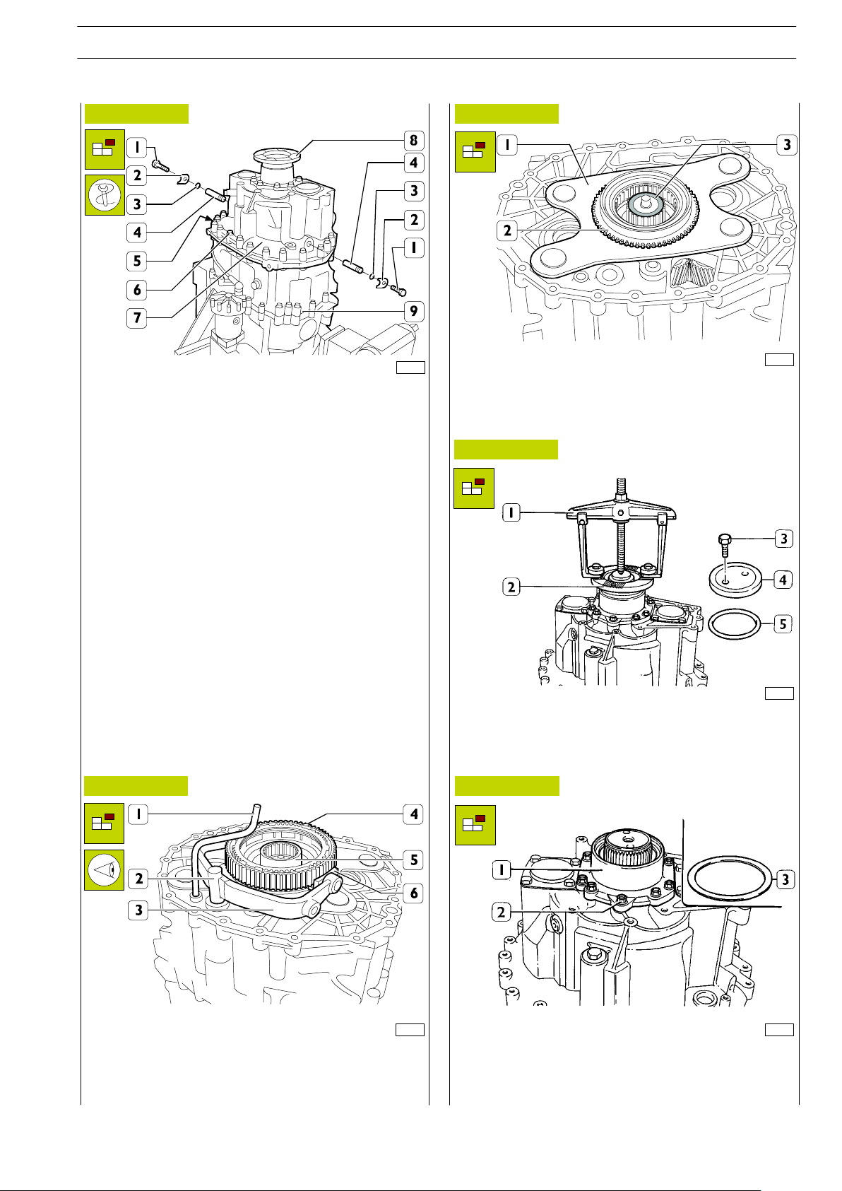
Removing the rear box
70831
70832
70833
70834
70835
Figure 10
Figure 11
Figure 12
Figure 13
Figure 14
Remove the screws (1) fixing the plates (2) fastening the pins
(4) and extract these together with the seal (3) from the rear
box (7).
Extract the two centring pins (5). Remove the screws (6).
Fit the eyebolt 99366811 to the sleeve (8) and, using special
ropes and lifter, detach the rear box (7) from the middle one
(9).
Remove the oil pipe (1). Note down the assembly position of
the fork (3) and plugs (6) and remove them. Remove: the rod
(2), synchronizing device assembly (4) and connecting sleeve
(5).
Remove the adjustment ring (3) and the plate (1) together
with the coupling body (2).
Removing the rear box
Remove the screws (3), disc (4) and seal (5) and extract the
sleeve (2) from the spider shaft. Should extraction prove
difficult, use an extractor (1) applied as illustrated in the figure.
Remove the screws (2) andtake off the cover (1). Remove the
spider shaft bearing end float adjustment ring (3).
GEARBOX EuroTronic 12 AS 2301 D.D./O.D. 127
STRALIS AT/AD
Print 603.93.141 Base - January 2003
45946
70837
70836
70838
70839
70840
Figure 15
Figure 16
Figure 17
Figure 18
Figure 19
Figure 20
Using a press, extract the spider shaft (1) from the supporting
roller bearing (2). Turn the rear box (3) upside-down and
extract the roller bearing (2).
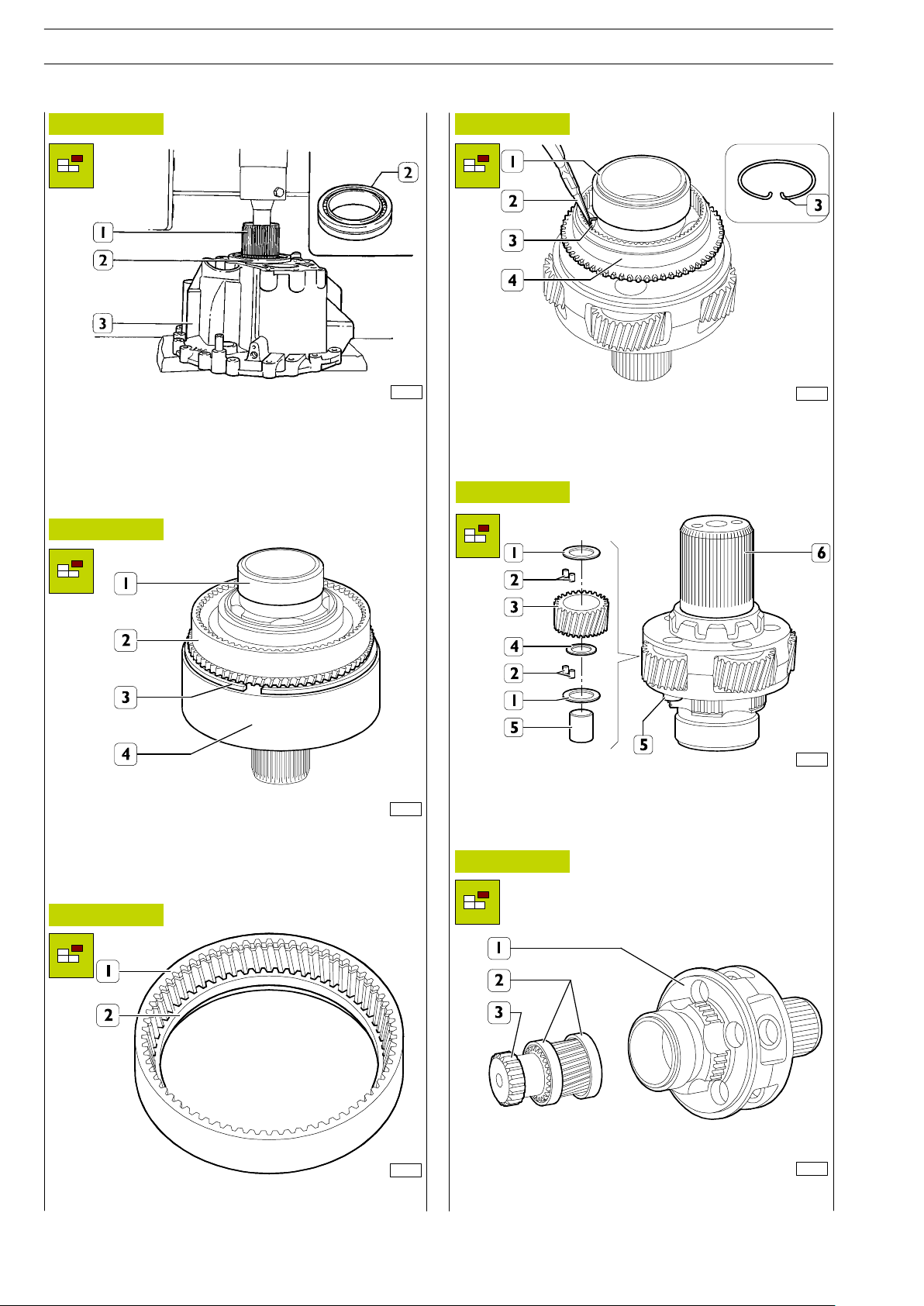
Removing the epicyclic reduction gear train
(E.R.G.)
Using a screwdriver, remove the circlip (3) fastening the ring
gear with internal toothing (4) to the ring gear with external
toothing (2) and remove them from the E.R.G. (1).
Extract the toothed ring (2) from the ring gear with internal
toothing (1).
Using pliers (2), tighten the ends of the circlip (3) and remove
the coupling body (4) from the E.R.G. shaft (1).
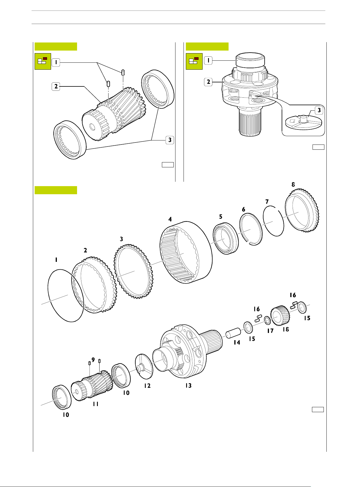
Using a punch, extract the pins (5) from the spider shaft (6).
Remove the planetary gears (3) from the spider shaft (6),
together with the rollers (2) and shim adjustment rings (1 and
4).
Extract the toothed shaft (3) from the spider shaft (1) together
with the rings (2).
128
GEARBOX EuroTronic 12 AS 2301 D.D./O.D.
STRALIS AT/AD
Base - January 2003 Print 603.93.141
70841
70843
70842
Figure 21 Figure 22
Extract one of the pins (1) from the toothed shaft (2) and
extract the rings (3) from this.
Using a suitable extractor, remove the roller bearing ring (1)
from the spider shaft (2).
Using a punch, extract the disc (3) from the inside of the spider
shaft (2).
PARTS COMPRISING THE E.R.G.
1. Circlip - 2. Ring gear with external toothing - 3. Toothed ring - 4. Ring gear with internal toothing - 5. Bearing - 6. Circlip - 7.
Circlip - 8. Coupling body - 9. Pins - 10. Ring - 11. Toothed spindle - 12. Disc - 13. Spider shaft - 14. Pin - 15. Shim adjustment
ring - 16. Rollers - 17. Shim adjustment ring - 18. Planetary gear.
Figure 23
GEARBOX EuroTronic 12 AS 2301 D.D./O.D. 129
STRALIS AT/AD
Print 603.93.141 Base - January 2003
70844
70840
70845
70982
70838
70983
Figure 24
Figure 25
Figure 26
Figure 27
Figure 28
Figure 29
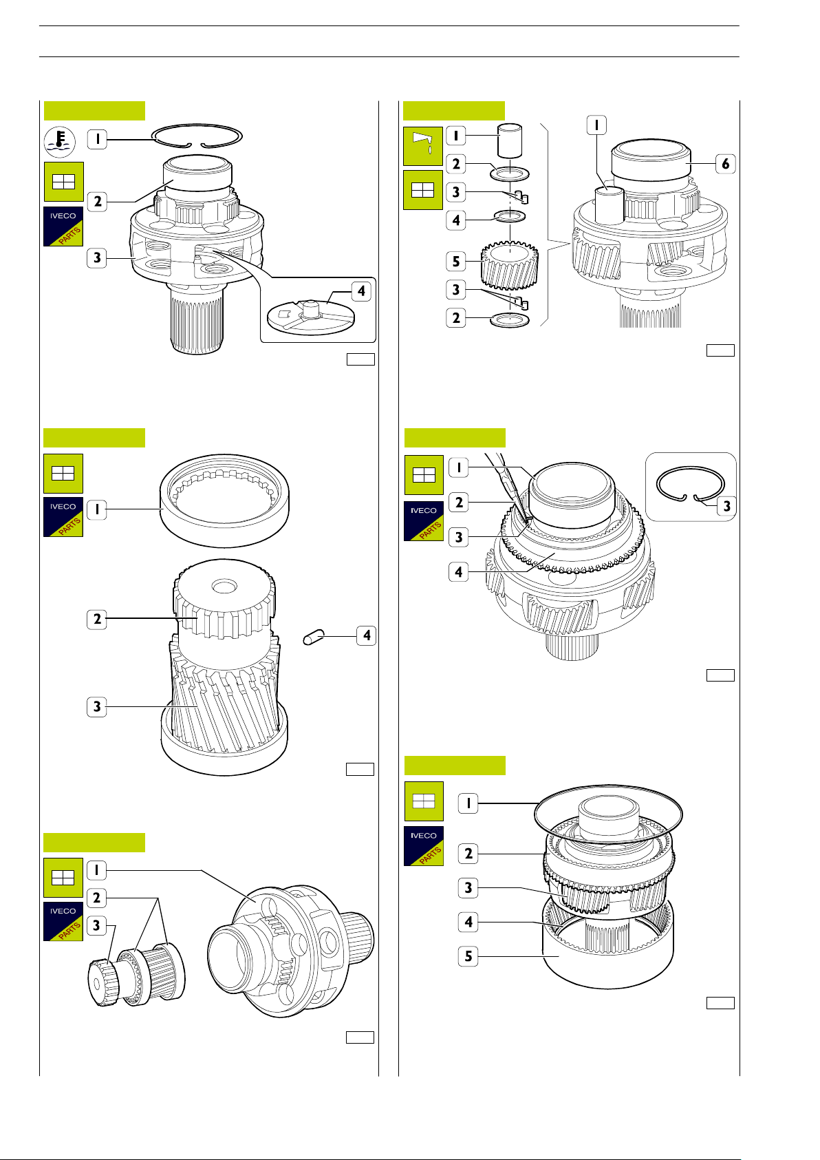
Heat the inside ring (2) of the roller bearing to 120qC and fit
it on the spider shaft (3).
Fit on the circlip (1). Fit on the disc (4).
Drive the rings (1 and 3) onto the toothed spindle (2) and fit
on the pin (4).
Insert the spindle (3) together with the rings (2) onto the
spider shaft (1).
Smear grease into the hole of the planetary gear (5) and insert
the rollers (3) with the associated shim adjustment rings (2 and
4). Fit the planetary gears (5) onto the spider shaft (6),
fastening them to it with the pins (1).
Using pliers (2), tighten the ends of the circlip (3) and fit the
coupling body (4) onto the E.R.G. shaft (1).
Fit the ring gear with internal toothing (5) onto the spider shaft
(3) together with the toothed ring (4), and the ring gear with
external toothing (2) and fasten the two ring gears with the
circlip (1).
130
GEARBOX EuroTronic 12 AS 2301 D.D./O.D.
STRALIS AT/AD
Base - January 2003 Print 603.93.141
Fitting the epicyclic reduction gear train (E.R.G.)
 Loading...