


 Loading...
ELECTRONICALLY CONTROLLED BRAKING SYSTEM EBS 2/ESP/EBL
STRALIS AT/AD/AS

”This document provides data, characteristics, instructions and methodology to perform repair interventions on the vehicle and its components.
Anyhow, this document is addressed to qualified and specialised personnel. Iveco commercial and assistance network personnel as well as all Iveco authorised points of assistance are specifically qualified and equipped to perform the repair interventions that are indicated in this document.
Before performing any intervention, check to have available the document relating to the vehicle model on which the intervention is being performed and also make sure that all accident prevention devices, such as, as a rough guide, goggles, helmet, gloves, shoes, as well as work tooling, lifting and transport tooling, etc., are available and efficient, and further make sure that the vehicle is put such a way that an intervention can be made in safety conditions.
Making interventions strictly observing the indications given here, as well as using specific tooling indicated, assures a correct repair intervention, execution timing observance and operators’ safety.
Each repair intervention must be finalised to the recovery of functionality, efficiency and safety conditions that are provided by Iveco.
Each intervention, on the vehicle, that is finalised to a modification, alteration or else, which is not authorised by Iveco, involves the exclusion of any responsibility for Iveco, and, in particular, where the vehicle is covered by a guarantee, each such intervention involves an immediate lapse of the guarantee.
Responsibility for Iveco in repair intervention execution is excluded.
Iveco is available to provide all clarifications necessary to make interventions, as well as to provide indications in cases and situations not included in this document.
Data and information contained in this document could result not to be updated owing to modifications made by Iveco at any moment for technical or commercial reasons, or because of the need to adapt the vehicle to law requirements in different countries.
In the case of a difference between what contained here and what actually found on the vehicle, please contact Iveco network before making any intervention.”
The data contained in this publication might fail to reflect the latest changes which the Manufacturer may introduce at any time, for technical or sales purposes, or to meet the requirements of local legislation.
Copy, even partial, of text and drawings is forbidden.
Publication Edited by: IVECO S.p.A. Customer Service
Lungo Stura Lazio , 15 10156 Torino - Italia
Print 603.93.321 - 1st Ed. 2004
Produced by:
B.U. TECHNICAL PUBLISHING
Iveco Technical Publications
Lungo Stura Lazio , 15
10156 Turin - Italy

STRALIS AT/AD/AS |
AIR SYSTEM - BRAKES EBS 2/ESP/EBL |
1 |
|
Pneumatic system - |
|
|
EBS 2/ESP/EBL brakes |
|
|
|
Page |
|
SYMBOLS FOR AIR/HYDRAULIC SYSTEM |
|
|
CIRCUIT DIAGRAMS |
|
|
(TANKS AND ACCUMULATORS) . . . . . . . . . . |
5 |
|
SYMBOLS FOR AIR/HYDRAULIC SYSTEM |
|
|
CIRCUIT DIAGRAMS (VALVES) . . . . . . . . . . . . |
6 |
|
SYMBOLS FOR AIR-HYDRAULIC SYSTEM |
|
|
DIAGRAMS (TANKS AND |
|
|
ACCUMULATORS) . . . . . . . . . . . . . . . . . . . . . . |
12 |
|
SYMBOLS FOR AIR/HYDRAULIC SYSTEM |
|
|
CIRCUIT DIAGRAMS (CONVERTERS, |
|
|
CYLINDERS AND CALLIPERS) . . . . . . . . . . . . . |
13 |
|
SYMBOLS FOR AIR/HYDRAULIC SYSTEM |
|
|
CIRCUIT DIAGRAMS |
|
|
(CALLIPERS AND CYLINDERS) . . . . . . . . . . . . |
14 |
|
SYMBOLS FOR AIR/HYDRAULIC SYSTEM |
|
|
CIRCUIT DIAGRAMS (SEMI-COUPLINGS |
|
|
AND COUPLING CONNECTORS) . . . . . . . . . |
15 |
|
SYMBOLS FOR AIR/HYDRAULIC SYSTEM |
|
|
CIRCUIT DIAGRAMS (SEMI-COUPLINGS |
|
|
AND COUPLING CONNECTORS) . . . . . . . . . |
16 |
|
SYMBOLS FOR AIR/HYDRAULIC SYSTEM |
|
|
CIRCUIT DIAGRAMS |
|
|
(INDICATORS AND SWITCHES) . . . . . . . . . . |
17 |
|
SYMBOLS FOR AIR/HYDRAULIC SYSTEM |
|
|
CIRCUIT DIAGRAMS (BRAKES) . . . . . . . . . . . . |
18 |
|
PIPINGS AND FITTINGS . . . . . . . . . . . . . . . . . . . . |
19 |
|
- In general . . . . . . . . . . . . . . . . . . . . . . . . . . . . . |
19 |
|
- Rigid pipings reflanging . . . . . . . . . . . . . . . . . . . |
19 |
|
- Rigid pipings bending . . . . . . . . . . . . . . . . . . . . |
20 |
|
- Rigid pipings cutting . . . . . . . . . . . . . . . . . . . . . |
20 |
|
- Flexible pipings replacement with traditional |
|
|
fittings . . . . . . . . . . . . . . . . . . . . . . . . . . . . . . . |
21 |
|
- Flexible pipings replacement with quick |
|
|
connection fittings . . . . . . . . . . . . . . . . . . . . . . |
22 |
|
EBS 2 (ELECTRONIC BRAKE SYSTEM) . . . . . . . . . |
24 |
|
- EBS Benefits . . . . . . . . . . . . . . . . . . . . . . . . . . |
24 |
|
- Tractor and trailer compatibility at any time . . |
24 |
|
- Complete fault-diagnosis structures . . . . . . . . |
24 |
Print 603.93.321 |
Base - May 2004 |

2 |
AIR SYSTEM - BRAKES EBS 2/ESP/EBL |
STRALIS AT/AD/AS |
|
|
|
|
Page |
OPERATING LOGIC . . . . . . . . . . . . . . . . . . . . . . . |
25 |
BRAKE SYSTEM . . . . . . . . . . . . . . . . . . . . . . . . . . . |
25 |
AUXILIARY BRAKE INTEGRATION . . . . . . . . . . . |
27 |
- ESP (Electronic Stability Program) . . . . . . . . . |
28 |
“ABS-EBL” SYSTEM (ANTI-LOCK BRAKE SYSTEM — |
|
ELECTRONIC BRAKE LIMITER) . . . . . . . . . . . . |
28 |
- “ABS” (Anti-Lock Brake System) . . . . . . . . . . |
28 |
- EBL (Electronic Brakes Limiter) . . . . . . . . . . . . |
29 |
- Operating Logic . . . . . . . . . . . . . . . . . . . . . . . |
29 |
- Braking system evolution . . . . . . . . . . . . . . . . |
29 |
BRAKING SYSTEMS . . . . . . . . . . . . . . . . . . . . . . . . |
30 |
- ABS-EBL working diagram for 4x2 vehicles |
|
(trucks and tractors, not including HR) |
|
with CURSOR 8 (F2B) engine . . . . . . . . . . . . |
30 |
- Working diagram for 6x2 vehicles (tractors) |
|
with CURSOR 8 (F2B) engine . . . . . . . . . . . . |
31 |
- ABS-EBL working diagram for 6x2 vehicles |
|
(tractors) with CURSOR 8 (F2B) engine . . . . |
32 |
-Working diagram for 6x2 vehicles (trucks) with CURSOR 8 (F2B) engine and with CURSOR 10
engine (F3A with mechanical suspensions) . . . |
33 |
- ABS-EBL working diagram for 6x2 vehicles (trucks) with CURSOR 8 (F2B) engine and with CURSOR 10
engine (F3A with mechanical suspensions) . . . |
34 |
- ABS-EBL working diagram for stand alone 4x2 |
|
vehicles (trucks) with CURSOR 8 (F2B) engine |
35 |
|
|
- ABS-EBL working diagram for 6x2C vehicles |
|
(trucks) with CURSOR 8 (F2B) engine . . . . . . |
36 |
|
|
- ABS-EBL working diagram for stand alone 6x2 |
|
vehicles (trucks) with CURSOR 8 (F2B) engine |
37 |
|
|
- EBS 2 working diagram for 4x2 vehicles (tractors) |
|
with CURSOR 10/13 engine . . . . . . . . . . . . . |
38 |
|
|
- EBS 2 working diagram for 4x2 T/FP-CT vehicles |
|
(tractors) with CURSOR 10/13 engine . . . . . |
39 |
|
|
- EBS 2 working diagram for 6x2 vehicles (tractors) |
|
with CURSOR 10/13 engine . . . . . . . . . . . . . |
40 |
|
|
|
Page |
- EBS 2 working diagram for 6x2 vehicles (trucks) |
|
with CURSOR 10/13 engine . . . . . . . . . . . . . |
41 |
- EBS 2 working diagram for 6x2 vehicles (trucks) |
|
with CURSOR 10/13 engine . . . . . . . . . . . . . |
42 |
- EBS 2 working diagram for 6x2 vehicles (trucks) |
|
with CURSOR 10/13 engine . . . . . . . . . . . . . |
43 |
- EBS 2 system components location on vehicle |
|
(tractors variant) . . . . . . . . . . . . . . . . . . . . . . . |
44 |
- ABS-EBL system components location |
|
(tractors variant) . . . . . . . . . . . . . . . . . . . . . . . |
45 |
DESCRIPTION . . . . . . . . . . . . . . . . . . . . . . . . . . . . |
46 |
- Service braking . . . . . . . . . . . . . . . . . . . . . . . . |
46 |
- Emergency braking . . . . . . . . . . . . . . . . . . . . . |
46 |
- Exhaust brake . . . . . . . . . . . . . . . . . . . . . . . . . |
46 |
- Parking brake . . . . . . . . . . . . . . . . . . . . . . . . . |
46 |
BRAKES . . . . . . . . . . . . . . . . . . . . . . . . . . . . . . . . . |
46 |
- Front and rear disk brakes |
|
(KNORR SN7 type) . . . . . . . . . . . . . . . . . . . . |
46 |
FAULT DIAGNOSIS . . . . . . . . . . . . . . . . . . . . . . . |
47 |
- Diagnosis Instruments . . . . . . . . . . . . . . . . . . . |
47 |
- Cluster Diagnosis . . . . . . . . . . . . . . . . . . . . . . |
48 |
- EBS 2 theoretical scheme . . . . . . . . . . . . . . . . |
63 |
TIGHTENING TORQUES . . . . . . . . . . . . . . . . . . . |
68 |
TOOLS . . . . . . . . . . . . . . . . . . . . . . . . . . . . . . . . . |
70 |
SPECIFICATIONS AND DATA - |
|
PNEUMATIC SYSTEM . . . . . . . . . . . . . . . . . . . . |
77 |
SPECIFICATIONS AND DATA - BRAKES . . . . . . |
82 |
CHECKS ON MAIN COMPONENTS |
|
OF BRAKE SYSTEM . . . . . . . . . . . . . . . . . . . . . . |
83 |
MAIN COMPONENTS OF THE BRAKING |
|
SYSTEM . . . . . . . . . . . . . . . . . . . . . . . . . . . . . . . |
85 |
- Compressor . . . . . . . . . . . . . . . . . . . . . . . . . . |
85 |
- Head locking screw tightness . . . . . . . . . . . . . |
85 |
- Fault diagnosis . . . . . . . . . . . . . . . . . . . . . . . . . |
86 |
- A.P.U. (Air Processing Unit) . . . . . . . . . . . . . . |
86 |
Base - May 2004 |
Print 603.93.321 |

STRALIS AT/AD/AS |
AIR SYSTEM - BRAKES EBS 2/ESP/EBL |
3 |
|
|
|
|
Page |
OPERATION . . . . . . . . . . . . . . . . . . . . . . . . . . . . . |
88 |
- Duplex control valve (vehicles without EBS) . |
92 |
- Fault Diagnosis (vehicles without EBS) . . . . . . |
92 |
- CBU (Central Brake Unit) |
|
(vehicles with EBS 2) . . . . . . . . . . . . . . . . . . . |
93 |
- Relay valve (vehicles without EBS) . . . . . . . . . |
95 |
- Fault Diagnosis (vehicles without EBS) . . . . . . |
95 |
- Coupling heads . . . . . . . . . . . . . . . . . . . . . . . . |
95 |
- Electropneumatic modulator |
|
(vehicles with EBS 2) . . . . . . . . . . . . . . . . . . . |
96 |
- Operation . . . . . . . . . . . . . . . . . . . . . . . . . . . . |
98 |
- Redundancy valve (for 4x2 and 6x2 trucks) . . |
99 |
- ABS solenoid valve . . . . . . . . . . . . . . . . . . . . . |
99 |
- Dual stop valve . . . . . . . . . . . . . . . . . . . . . . . . |
99 |
- Triple servo control valve |
|
(vehicles without EBS) . . . . . . . . . . . . . . . . . . |
99 |
- Predominance control . . . . . . . . . . . . . . . . . . |
100 |
- Fault Diagnosis . . . . . . . . . . . . . . . . . . . . . . . . |
100 |
- Trailer drive servo-assisted distributor |
|
(vehicles with EBS 2) . . . . . . . . . . . . . . . . . . . |
101 |
- Operation . . . . . . . . . . . . . . . . . . . . . . . . . . . . |
102 |
- Pressure test point valve . . . . . . . . . . . . . . . . . |
104 |
- Parking brake hand control valve |
|
(vehicles suited to towing) . . . . . . . . . . . . . . . |
104 |
- Fault Diagnosis (parking brake control valve) . |
104 |
- Parking brake control manual distributor |
|
(standby vehicles) . . . . . . . . . . . . . . . . . . . . . . |
105 |
- Manual control valve to slow down |
|
the trailer (optional extra) . . . . . . . . . . . . . . . |
105 |
- Fault Diagnosis (parking brake control valve) . |
105 |
- Controlled pressure valve . . . . . . . . . . . . . . . . |
106 |
- Fault Diagnosis . . . . . . . . . . . . . . . . . . . . . . . . |
106 |
- Check valve (vehicles suited to towing) . . . . . |
106 |
- Low-pressure switch . . . . . . . . . . . . . . . . . . . . |
106 |
- Electro-pneumatic valve for ASR . . . . . . . . . . |
107 |
|
Page |
- Speed sensor . . . . . . . . . . . . . . . . . . . . . . . . . |
107 |
- Phonic wheels . . . . . . . . . . . . . . . . . . . . . . . . . |
107 |
- Electronic control unit . . . . . . . . . . . . . . . . . . |
107 |
- Pressure sensor . . . . . . . . . . . . . . . . . . . . . . . . |
107 |
- Diaphragm brake cylinder (for front and |
|
added front axle disc brake) . . . . . . . . . . . . . . |
108 |
- Combined brake cylinder |
|
(for front and rear disc brake) . . . . . . . . . . . . |
108 |
- Combined cylinder emergency brake |
|
release device . . . . . . . . . . . . . . . . . . . . . . . . . |
109 |
- Repairs . . . . . . . . . . . . . . . . . . . . . . . . . . . . . . |
109 |
- Fault Diagnosis . . . . . . . . . . . . . . . . . . . . . . . . |
109 |
DISC BRAKES KNORR TYPE (CALIPER SN7) . . . |
110 |
- Operation . . . . . . . . . . . . . . . . . . . . . . . . . . . . |
111 |
CHECKS . . . . . . . . . . . . . . . . . . . . . . . . . . . . . . . . . |
111 |
- Checking the automatic play recovery system |
|
efficiency . . . . . . . . . . . . . . . . . . . . . . . . . . . . . |
111 |
- Brake caliper components . . . . . . . . . . . . . . . |
112 |
- Check of braking seals thickness . . . . . . . . . . . |
113 |
OVERHAULING FRONT DISC BRAKES . . . . . . . . |
114 |
- Replacing brake linings . . . . . . . . . . . . . . . . . . |
114 |
- Removing and refitting brake callipers . . . . . . . |
117 |
- Removal . . . . . . . . . . . . . . . . . . . . . . . . . . . . . |
117 |
- Refitting . . . . . . . . . . . . . . . . . . . . . . . . . . . . . . |
118 |
- Removing and refitting wheel hubs . . . . . . . . . |
118 |
- Removal . . . . . . . . . . . . . . . . . . . . . . . . . . . . . |
118 |
- Refitting . . . . . . . . . . . . . . . . . . . . . . . . . . . . . . |
119 |
BRAKE CALIPER OVERHAUL . . . . . . . . . . . . . . . . |
120 |
- Disassembly . . . . . . . . . . . . . . . . . . . . . . . . . . |
120 |
- Component part cleaning and check . . . . . . . |
121 |
- Assembly . . . . . . . . . . . . . . . . . . . . . . . . . . . . |
121 |
OVERHAULING REAR DISC BRAKES . . . . . . . . . |
123 |
- Replacing brake linings . . . . . . . . . . . . . . . . . . |
123 |
Print 603.93.321 |
Base - May 2004 |

4 |
AIR SYSTEM - BRAKES EBS 2/ESP/EBL |
STRALIS AT/AD/AS |
|
|
|
|
Page |
|
OVERHAULING BRAKE DISCS . . . . . . . . . |
. . . . . . |
126 |
|
TURNING AND GRINDING BRAKE DISCS . . . . . |
126 |
|
Base - May 2004 |
Print 603.93.321 |
STRALIS AT/AD/AS |
AIR SYSTEM - BRAKES EBS 2/ESP/EBL |
5 |
|
|
|
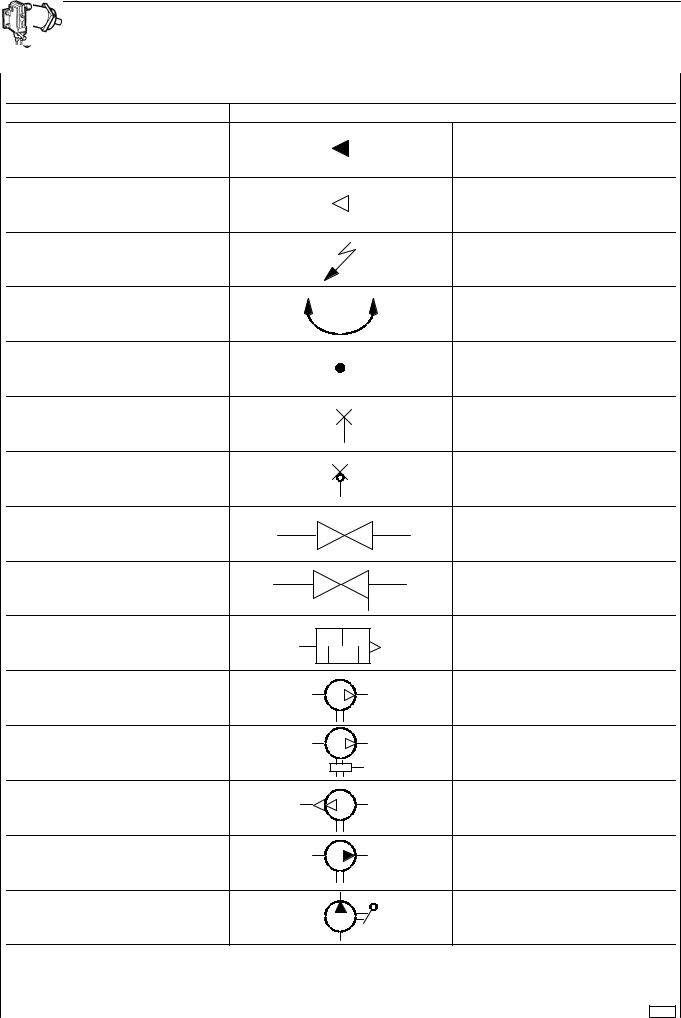
SYMBOLS FOR AIR/HYDRAULIC SYSTEM CIRCUIT DIAGRAMS (TANKS AND ACCUMULATORS)
DESCRIPTION |
|
SYMBOL |
HYDRAULIC FLOW |
|
|
AIR FLOW |
|
|
ELECTRICAL LINE |
|
|
ABLE TO ROTATE |
|
|
CROSSOVER OF CONNECTED LINES |
|
|
PRESSURE TEST POINT |
|
|
QUICK-CONNECTION COUPLING |
|
|
COCK |
|
|
COCK WITH OUTLET |
1 |
2 |
|
|
|
SILENCER |
|
|
COMPRESSOR |
0 |
2 |
ENERGY SAVING COMPRESSOR |
0 |
2 |
|
|
|
|
|
4 |
VACUUM PUMP |
3 |
2 |
HYDRAULIC PUMP |
0 |
2 |
|
|
|
HYDRAULIC HAND PUMP |
|
|
32780
Print 603.93.321 |
Base - May 2004 |
6 AIR SYSTEM - BRAKES EBS 2/ESP/EBL STRALIS AT/AD/AS
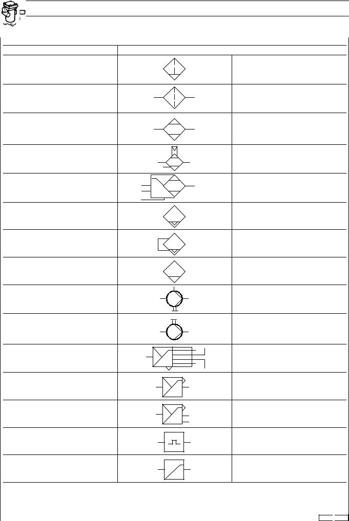
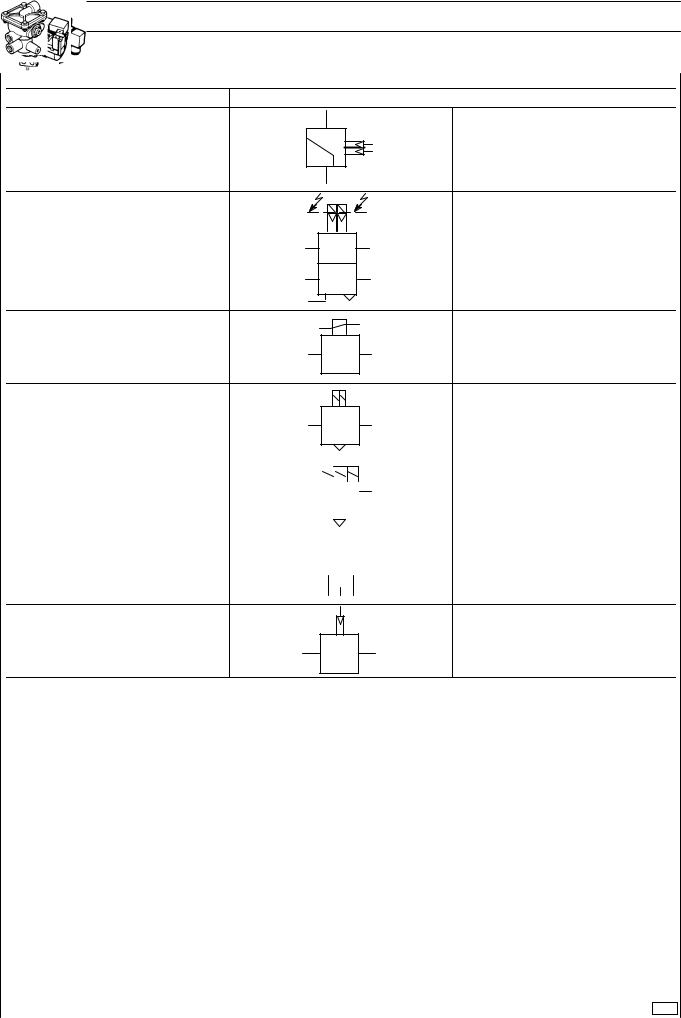
SYMBOLS FOR AIR/HYDRAULIC SYSTEM CIRCUIT DIAGRAMS (VALVES)
DESCRIPTION |
|
SYMBOL |
CONDENSATE SEPARATOR |
|
|
FILTER |
1 |
2 |
DEHUMIDIFIER |
1 |
2 |
|
21 |
4 |
DEHUMIDIFIER |
1 |
|
|
22 |
|
DEHUMIDIFIER WITH BUILT-IN |
21 |
1 |
REGULATOR |
22 |
|
|
23 |
|
AUTOMATIC CONDENSATE |
|
|
DRAIN VALVE |
|
|
CONTROLLED CONDENSATE |
|
|
DRAIN VALVE |
|
|
HAND CONDENSATE DRAIN VALVE |
|
|
|
|
7 |
CONTROLLED ANTI-ICING UNIT |
1 |
2 |
AUTOMATIC ANTI-ICING UNIT |
1 |
2 |
|
||
PRESSURE REGULATOR WITH |
1 |
21 23 |
|
||
INDEPENDENT CIRCUIT |
|
|
|
22 24 |
|
|
|
|
PRESSURE CONTROLLER |
1 |
21 |
PRESSURE CONTROLLER |
1 |
21 |
|
|
23 |
PRESSURE CONTROLLER |
1 |
2 |
(GOVERNOR) |
||
PRESSURE LIMITING VALVE |
1 |
2 |
32782 
 32783
32783
Base - May 2004 |
Print 603.93.321 |

STRALIS AT/AD/AS AIR SYSTEM - BRAKES EBS 2/ESP/EBL 7
SYMBOLS FOR AIR/HYDRAULIC SYSTEM CIRCUIT DIAGRAMS (VALVES)
DESCRIPTION |
|
|
SYMBOL |
PROPORTIONAL REDUCING VALVE |
1 |
2 |
|
MATCHING VALVE |
1 |
2 |
|
FOUR CIRCUIT PROTECTION VALVE |
1 |
21 23 |
|
|
|
||
|
|
22 |
24 |
THREE CIRCUIT PROTECTION |
|
21 |
|
1 |
23 |
|
|
VALVE |
|
||
|
22 |
|
|
|
|
|
|
TWO CIRCUIT PROTECTION VALVE |
1 |
21 |
|
|
|
||
|
|
22 |
|
NON-RETURN AIR INLET VALVE |
1 |
2 |
|
|
|
||
LIMITED RETURN AIR INLET VALVE |
1 |
2 |
|
|
|
||
SAFETY VALVE |
|
|
|
CHECK VALVE |
1 |
2 |
|
|
|
||
|
|
2 |
|
CHECK VALVE |
|
2 |
|
|
|
|
|
1
2
DOUBLE SHUT-OFF VALVE
11 12
DIFFERENTIAL DOUBLE SHUT-OFF |
|
U |
|
|
|
VALVE |
M |
S |
THROTTLE VALVE WITH QUICK
RETURN 1 2
THROTTLE VALVE
32783 
 32784
32784 
 32785
32785
Print 603.93.321 |
Base - May 2004 |
8 AIR SYSTEM - BRAKES EBS 2/ESP/EBL STRALIS AT/AD/AS
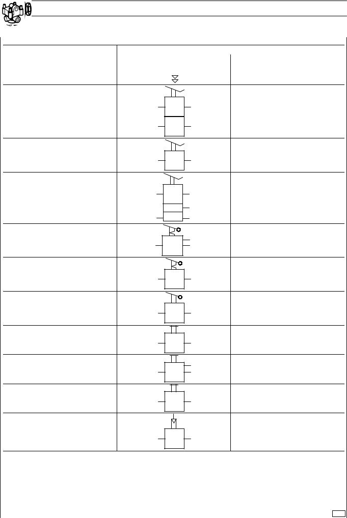
SYMBOLS FOR AIR/HYDRAULIC SYSTEM CIRCUIT DIAGRAMS (VALVES)
DESCRIPTION |
|
|
|
|
SYMBOL |
DUMP VALVE |
1 |
|
|
|
2 |
|
|
|
|||
|
|
|
|||
|
|
|
|
|
|
|
|
|
|
|
|
BRAKE CONTROL VALVE |
11 |
A |
21 |
|
|
|
|
|
12 |
P |
22 |
BRAKE CONTROL VALVE |
11 |
|
21 |
|
|
||
BRAKE CONTROL VALVE |
11 |
|
21 |
|
|
|
|
|
|
|
4 |
|
12 |
|
22 |
PARKING BRAKE CONTROL VALVE |
|
|
21 |
|
11 |
|
22 |
PARKING BRAKE CONTROL VALVE |
1 |
|
2 |
|
|
||
BRAKE VALVE |
1 |
|
2 |
|
|
||
CONTROL VALVE |
1 |
|
2 |
|
|
||
CONTROL VALVE |
|
|
21 |
1 |
|
22 |
|
|
|
||
RETARDER CONTROL VALVE |
13 |
R |
23 |
|
|||
SERVO CONTROL VALVE |
|
|
4 |
|
|
|
|
|
1 |
|
2 |
32786
Base - May 2004 |
Print 603.93.321 |
STRALIS AT/AD/AS AIR SYSTEM - BRAKES EBS 2/ESP/EBL 9
SYMBOLS FOR AIR/HYDRAULIC SYSTEM CIRCUIT DIAGRAMS (VALVES)
DESCRIPTION |
SYMBOL |
41
 42
42
SERVO CONTROL VALVE
|
1 |
2 |
|
|
4 |
SERVO CONTROL VALVE FOR |
|
|
SINGLE LINE |
1 |
2 |
|
|
41 |
42 |
43 |
|
|
||
TRAILER BRAKING TRIPLE |
|
|
|
CONTROL VALVE |
1 |
|
2 |
|
|
||
|
41 |
42 |
43 |
TRAILER BRAKING TRIPLE |
|
||
|
|
|
|
CONTROL VALVE WITH BUILT-IN |
|
|
|
SERVO SWITCHING |
11 |
|
22 |
|
12 |
|
|
LOAD PROPORTIONING VALVE |
1 |
|
2 |
|
|
|
|
DUAL LOAD PROPORTIONING |
11 |
|
21 |
12 |
|
22 |
|
VALVE |
|
||
|
|
|
|
LOAD PROPORTIONING VALVE |
12 |
|
21 |
11 |
|
||
WITH BY-PASS |
|
|
|
|
|
|
LOAD PROPORTIONING VALVE |
1 |
2 |
WITH BUILT-IN RELAY |
|
|
4
4
LOAD PROPORTIONING VALVE
WITH BUILT-IN RELAY WITH AIR 1 2
CONTROL
41 42
32786 
 32787
32787
Print 603.93.321 |
Base - May 2004 |
10 AIR SYSTEM - BRAKES EBS 2/ESP/EBL STRALIS AT/AD/AS
SYMBOLS FOR AIR/HYDRAULIC SYSTEM CIRCUIT DIAGRAMS (VALVES)
DESCRIPTION |
|
|
|
|
|
|
|
|
SYMBOL |
LOAD PROPORTIONING VALVE |
1 |
|
|
|
|
|
|
2 |
|
|
|
|
|
|
|
||||
WITH AIR CONTROL |
|
|
|
|
|
|
|
|
|
|
41 |
|
42 |
|
|||||
|
|
||||||||
|
|
|
|
|
|
|
|
|
|
LOAD PROPORTIONING VALVE |
1 |
|
|
|
|
|
|
|
2 |
|
|
|
|
|
|
|
|||
|
|
|
|
||||||
|
|
|
|
|
|
|
|
|
|
WITH AIR CONTROL |
|
|
|
|
|
4 |
|
|
|
|
|
|
|
|
|
|
|
||
|
|
|
|
|
|
|
|
|
|
|
|
|
|
|
|
|
|||
PROPORTIONAL REDUCING VALVE |
1 |
|
|
|
|
2 |
|||
|
|
|
|
||||||
|
|
4 |
SLAVED PROPORTIONAL |
|
|
REDUCING VALVE |
1 |
2 |
|
||
|
1 |
2 |
STROKE LIMITING VALVE |
|
|
|
|
1
LEVELLING VALVE
21 
 22
22
1 2
LEVELLING VALVE
12 

 23
23
LEVELLING VALVE WITH BUILT-IN |
|
|
TRAVEL LIMITER |
11 |
21 |
HAND OPERATED SUSPENSION |
23 |
|
|
|
24 |
|
|
|
|||
RAISING CONTROL VALVE |
21 |
|
|
22 |
|
|
|
|
|||
|
|
|
|
|
|
|
|
|
|
|
|
32787 
 32788
32788
Base - May 2004 |
Print 603.93.321 |
STRALIS AT/AD/AS AIR SYSTEM - BRAKES EBS 2/ESP/EBL 11
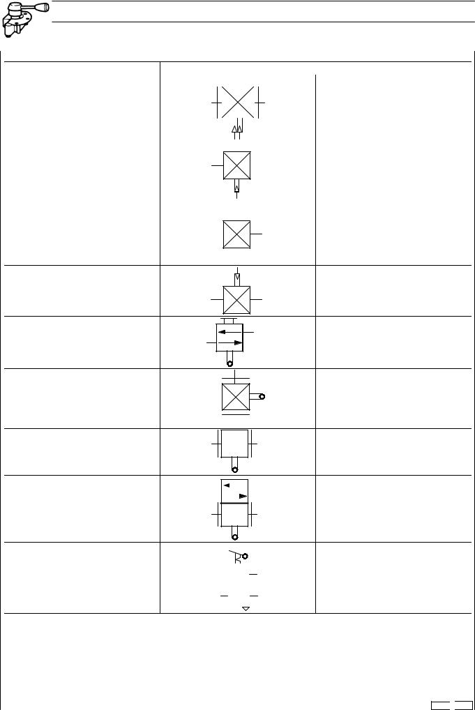
SYMBOLS FOR AIR/HYDRAULIC SYSTEM CIRCUIT DIAGRAMS (VALVES)
DESCRIPTION |
|
SYMBOL |
|
|
2 |
PROPORTIONAL CONTROL VALVE |
|
42 |
|
41 |
|
|
|
|
|
|
1 |
|
13 |
|
HAND OPERATED SUSPENSION |
11 |
21 |
CONTROL VALVE WITH |
|
|
ELECTRICAL MONITORING |
12 |
22 |
|
||
|
1 |
3 |
ELECTROPNEUMATIC VALVE |
1 |
2 |
|
ELECTROPNEUMATIC VALVE |
1 |
|
|
|
|
|
2 |
||
|
|
|
|
|
|
||||
|
|
|
|
|
|
|
|
|
|
ELECTROPNEUMATIC VALVE |
1 |
|
|
|
|
|
21 |
||
|
|
|
|
|
|||||
|
|
|
|
|
|||||
|
|
|
|
|
|
22 |
|||
|
|
|
|
|
|
|
|||
|
|
|
|
|
|
|
|
||
|
|
|
|
|
|
|
|
|
|
|
|
|
|
|
|
|
|
||
|
VR |
|
|
|
|
|
HZ2 |
||
|
|
ABS |
|
|
|||||
|
|
|
|
||||||
HYDRAULIC MODULATOR FOR ABS |
VL |
|
|
|
|
|
|
HZ1 |
|
|
|
|
|
|
|
||||
|
|
|
|
|
|
|
|
|
|
HL HR
4
AUGMENTER VALVE
1 2
32788
Print 603.93.321 |
Base - May 2004 |
12 AIR SYSTEM - BRAKES EBS 2/ESP/EBL STRALIS AT/AD/AS
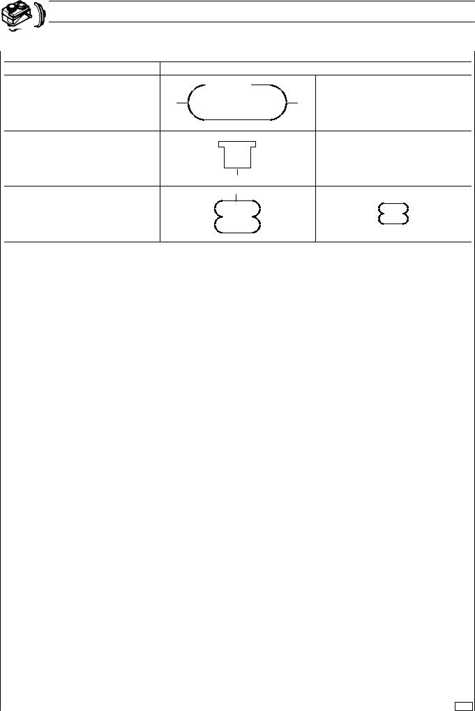
SYMBOLS FOR AIR-HYDRAULIC SYSTEM DIAGRAMS (TANKS AND ACCUMULATORS)
DESCRIPTION |
|
SYMBOL |
|
|
|
COMPRESSED AIR TANK
BRAKE FLUID RESERVOIR
AIR SPRING
32789
Base - May 2004 |
Print 603.93.321 |
STRALIS AT/AD/AS |
AIR SYSTEM - BRAKES EBS 2/ESP/EBL |
13 |
|
|
|
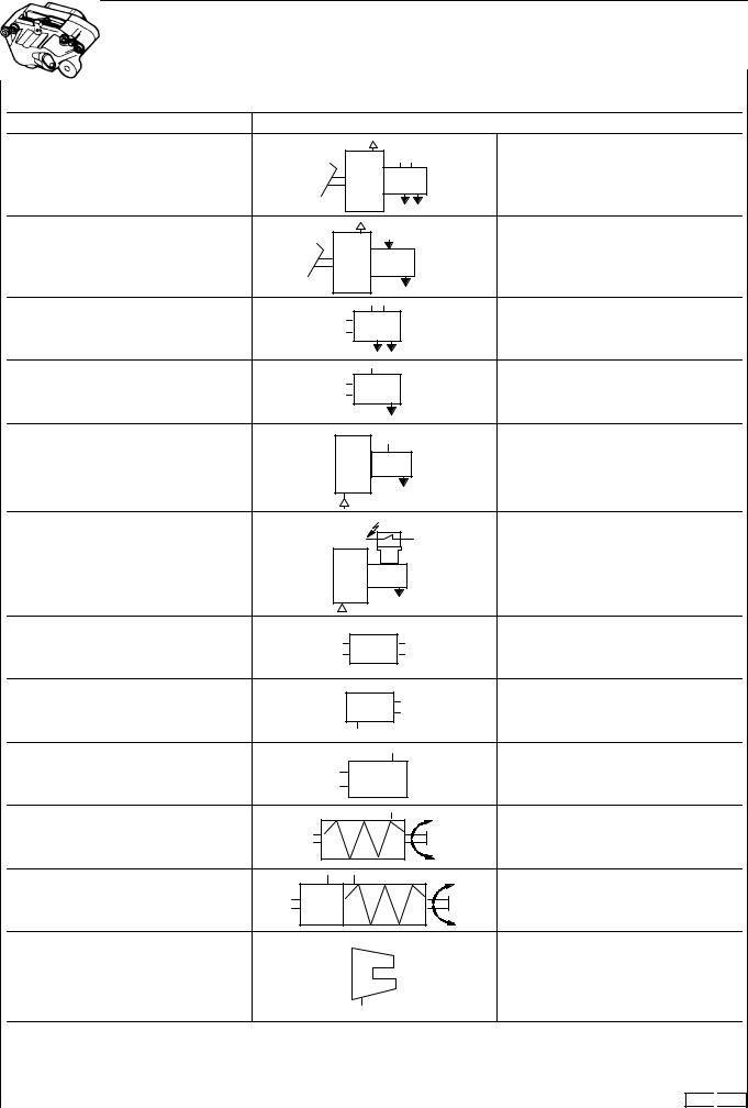
SYMBOLS FOR AIR/HYDRAULIC SYSTEM CIRCUIT DIAGRAMS (CONVERTERS, CYLINDERS AND CALLIPERS)
DESCRIPTION |
SYMBOL |
VACUUM BRAKE SERVO |
|
VACUUM BRAKE SERVO |
|
DUAL CIRCUIT MASTER CYLINDER |
|
SINGLE CIRCUIT MASTER CYLINDER |
|
AIR/HYDRAULIC CONVERTER |
|
AIR/HYDRAULIC CONVERTER |
|
HYDRAULIC BRAKE CYLINDER |
|
SLAVE CYLINDER |
|
BRAKE CYLINDER |
|
SPRING CYLINDER |
|
COMBINED BRAKE CYLINDER |
|
FIXED DISC BRAKE CALLIPER |
|
32790 
 32791
32791
Print 603.93.321 |
Base - May 2004 |
14 |
AIR SYSTEM - BRAKES EBS 2/ESP/EBL |
STRALIS AT/AD/AS |
|
|
|
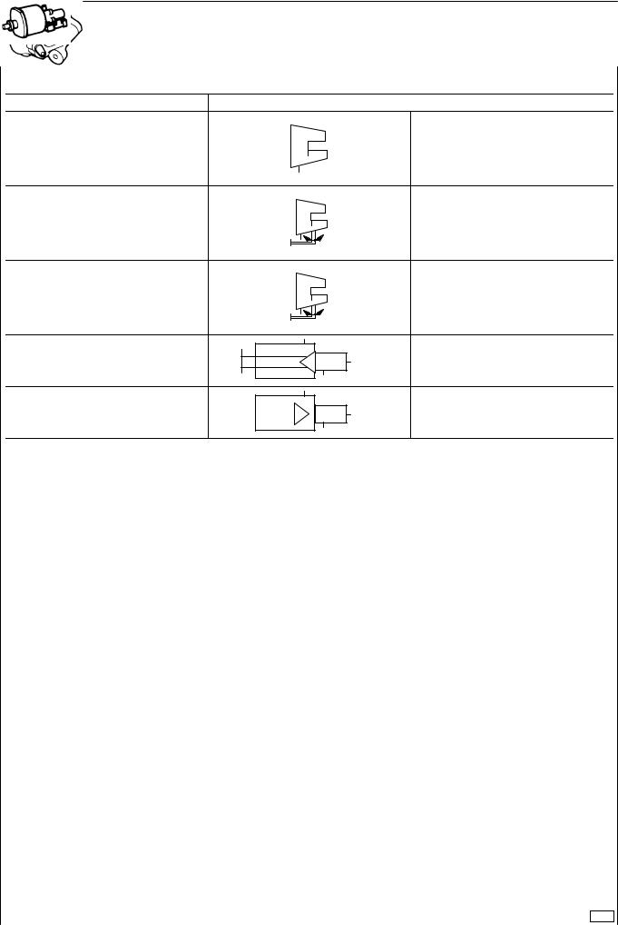
SYMBOLS FOR AIR/HYDRAULIC SYSTEM CIRCUIT DIAGRAMS (CALLIPERS AND CYLINDERS)
DESCRIPTION |
SYMBOL |
FLOATING DISC BRAKE CALLIPER
FLOATING DISC BRAKE CALLIPER
WITH PARKING
MECHANICAL FLOATING DISC
BRAKE CALLIPER
SERVO CLUTCH
SERVO CLUTCH
32791
Base - May 2004 |
Print 603.93.321 |

STRALIS AT/AD/AS |
AIR SYSTEM - BRAKES EBS 2/ESP/EBL |
15 |
|
|
|
SYMBOLS FOR AIR/HYDRAULIC SYSTEM CIRCUIT DIAGRAMS (SEMI-COUPLINGS AND COUPLING CONNECTORS)
DESCRIPTION |
|
|
|
|
|
|
|
|
|
SYMBOL |
|
|
|
|
|
|
|
|
|
|
|
|
|
|
|
|
|
|
|
|
|
|
A
“ISO” SEMI-COUPLING
M
ISO VERSION
 A
A
“ISO” SEMI-COUPLING
 M
M
VERSION WITH ISO COUPLINGS
A
“CUNA” SEMI-COUPLING
B
ITALIAN VERSION
M
“CUNA” SEMI-COUPLING
A
A
“NATO” SEMI-COUPLING
M
NATO VERSION
32792 
 32793
32793
Print 603.93.321 |
Base - May 2004 |
16 |
AIR SYSTEM - BRAKES EBS 2/ESP/EBL |
STRALIS AT/AD/AS |
|
|
|
SYMBOLS FOR AIR/HYDRAULIC SYSTEM CIRCUIT DIAGRAMS (SEMI-COUPLINGS AND COUPLING CONNECTORS)
DESCRIPTION |
|
|
|
|
|
|
|
|
|
|
|
|
|
|
SYMBOL |
||
|
|
|
|
|
|
|
|
|
|
|
|
|
|
|
|
|
|
|
|
|
|
|
|
|
|
|
|
|
|
|
|
|
|
|
|
|
|
|
|
|
|
|
|
|
|
|
|
|
|
|
|
|
|
4
1 5
2 3
V
Z
A
SINGLE LINE VERSION


 A
A
M
SEMI-COUPLING
V
Z
A
SINGLE LINE VERSION
12
22
SEMI-COUPLING
4
 2
2
SINGLE LINE VERSION
12


 A
A
22
M
SEMI-COUPLING
4
1  2
2
SINGLE LINE VERSION
32793
Base - May 2004 |
Print 603.93.321 |
STRALIS AT/AD/AS |
AIR SYSTEM - BRAKES EBS 2/ESP/EBL |
17 |
|
|
|
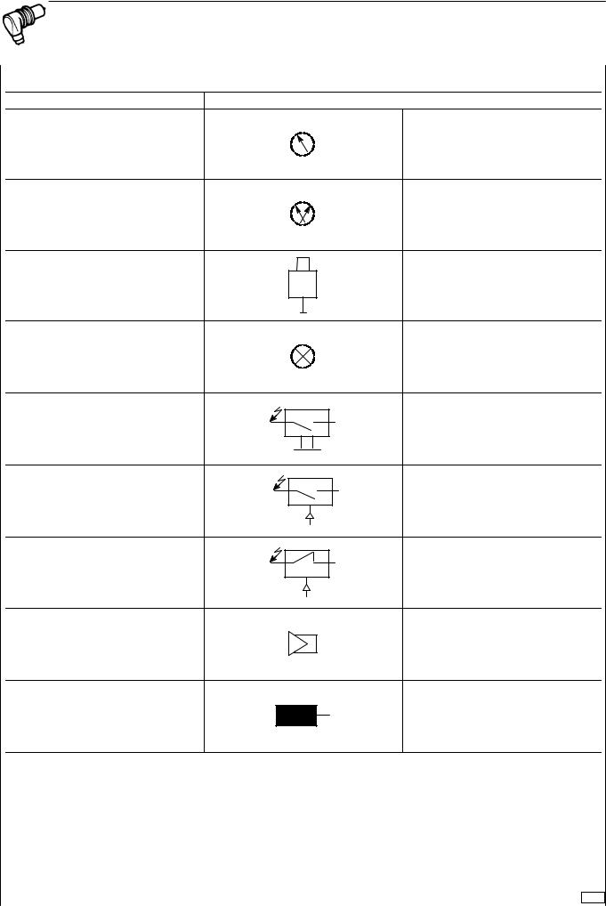
SYMBOLS FOR AIR/HYDRAULIC SYSTEM CIRCUIT DIAGRAMS (INDICATORS AND SWITCHES)
DESCRIPTION |
SYMBOL |
PRESSURE GAUGE |
|
PRESSURE GAUGE |
|
PRESSURE SENDING UNIT |
|
LAMP |
|
MECHANICAL SWITCH |
|
PRESSURE SWITCH |
|
LOW PRESSURE SWITCH |
|
AUDIBLE WARNING |
|
SENSOR |
|
32794
Print 603.93.321 |
Base - May 2004 |

18 AIR SYSTEM - BRAKES EBS 2/ESP/EBL STRALIS AT/AD/AS
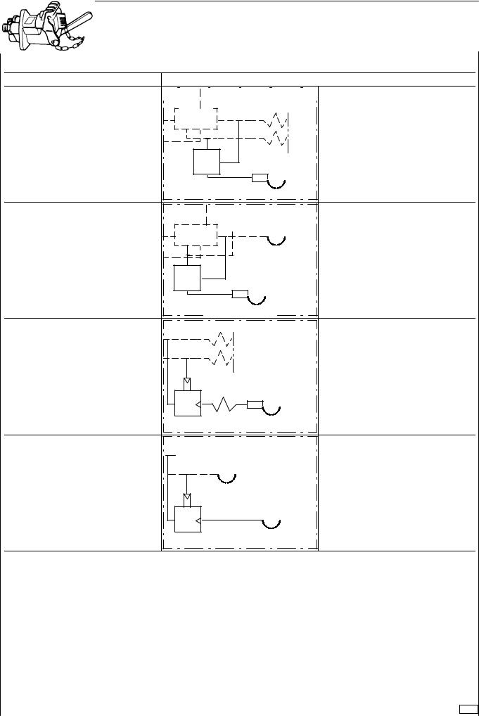
SYMBOLS FOR AIR/HYDRAULIC SYSTEM CIRCUIT DIAGRAMS (BRAKES)
DESCRIPTION |
SYMBOL |
SINGLE CYLINDER HYDRAULIC |
|
BRAKE |
|
TWIN CYLINDER HYDRAULIC BRAKE
DUAL SERVO HYDRAULIC BRAKE
DUAL SERVO HYDRAULIC BRAKE
WITH PARKING BRAKE
SINGLE CAM OPERATED BRAKE
TWIN DUAL CAM OPERATED BRAKE
32795
Base - May 2004 |
Print 603.93.321 |
STRALIS AT/AD/AS |
AIR SYSTEM - BRAKES EBS 2/ESP/EBL |
19 |
|
|
|
799512 PIPINGS AND FITTINGS
In general
Hydraulic system pipings for industrial vehicles are currently of two types:
-Flexible ones made of polyamide with single-layered or
double-layered structure and in the following diameters ( 6-8-10-12-16 mm) equipped with spares in meters.
- Rigid metal pipings |
in |
the following |
diameters |
( 4.75-6.35-8-10-12 |
mm). |
Pipings from |
4.75 to |
10 mm are supplied as spares in straight 4-5-6 m crop ends, while those exceeding 10 mm are supplied as spares already cut, bent and reflanged.
Rigid pipings reflanging
Figure 1
31971
RIGID PIPINGS REFLANGING REPRESENTATION
Reflanging type A
Figure 2
Arrange on a press 99386523 (3) small blocks (1) so that the punched numbers, showing the piping number to be worked, are facing the matrix die (2). The choice of the matrix die (2) depends on the diameter of the piping to be reflanged. Moreover, on every matrix die (2) the diameter of the piping is punched for which the same one can be used.
Figure 3
31973
Burr piping (1), insert union (2) and place it between small blocks (3) abutting pin (5). Lock piping (1) with screw (4).
Figure 4
31974
Take back pin (4) to its neutral position. Screw screw (1) till matrix die (2) comes to abut against small blocks (3) thereby shaping the piping (5) end.
Reflanging type B
Figure 5
31975
Assemble matrix die (2) on press 99386523 (1).
For the reflanging process comply with what has been stated above for reflanging type A.
Print 603.93.321 |
Base - May 2004 |
20 AIR SYSTEM - BRAKES EBS 2/ESP/EBL
Reflanging type C
Figure 6
Key on piping (1) nut (2) and ring (3).
Figure 7
31977
Assemble union (2) and tighten so that ring (3, Figure 6) is locked on piping (1).
Rigid pipings bending
Figure 8
Assemble tool (1) 99386523 choosing parts (2) and (3) depending on the diameter of pipings to be bent.
STRALIS AT/AD/AS
Figure 9
Place piping (1) into tool (3) and operating on lever (2) bend the piping.
Figure 10
In order to free piping (2) from tool (3), operate on lever (1).
Rigid pipings cutting
Figure 11
31981
Place piping (2) into tool (3) 99386523 and tighten screw (1). Keeping piping (2) still, rotate tool (3) till the piping is completely cut.
Base - May 2004 |
Print 603.93.321 |
STRALIS AT/AD/AS |
AIR SYSTEM - BRAKES EBS 2/ESP/EBL |
21 |
|
|
|
After having cut the piping, burr and shape the end as previously described.
Rotating tool (3) around piping (2), screw (1) is
!loosened. In order to completely cut the piping, it is then necessary to tighten screw (1) when it loosening.
Flexible pipings replacement with traditional fittings
Strictly comply with the following instructions:
Figure 12
10397
-Use
-Check the spare pipe status, on which no cracks, cuts or nickings must be detected;
-Cut the pipe at 90° with respect to the axis through a suitable pipe-cutting pliers 99387050 at the necessary length;
Insert on the pipe in the following order:
-nut (3), pressure ring (2) (its greater thickness must be facing nut (3) and reinforcement bush (1));
-the bush must be in perfect conditions (it must not have either distortions or hammering traces).
Figure 13
A=
B= WRONG ASSEMBLY
-Key the reinforcement bush with tool 99372219 guaranteeing the contact between its flange and the pipe end;
-make sure that the pipe end penetrates into the suitable rake groove obtained in the flange.
-Carry out abutment ring reflanging upon assembly on the vehicle or work bench on a fitting.
-The exerted pressure and the final distance from front pressure ring edge to reinforcement bush edge must be those mentioned in the table below.
In case of a bad assembly, never use the pipe after
!having extracted bush and abutment ring.
|
Pipe |
Distance between |
Assembling |
|
|
|
bush edge and ring |
pressure |
|
|
mm |
mm (*) |
N/mm2 |
|
|
|
|
|
|
Double- |
6 x 1 |
from 1 to 1.5 |
0.040 |
|
|
|
|
||
|
|
|
||
layered |
8 x 1 |
from 2 to 2.5 |
0.050 |
|
|
|
|
|
|
|
10 x 1.5 |
from 2 to 2.5 |
0.050 |
|
Single- |
|
|
|
|
12 x 1.6 |
from 2 to 2.5 |
0.060 |
||
layered |
|
|
|
|
16 x 2.34 |
from 3 to 3.5 |
0.060 |
||
|
||||
|
|
|
|
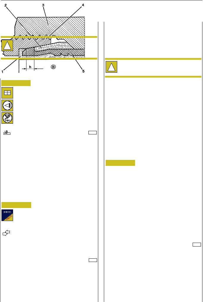
(*) See reference h, Figure 14.
Figure 14
1.Reinforcement bush - 2. Pressure ring -
3.Nut - 4. Fitting - 5. Pipe -
h.Distance between bush edge and ring edge (see table).
Insert the thereby-prepared piping end into the fitting body till the reinforcement bush flange rests within the suitable seat:
-For closing the nut on the fitting, initially screw it manually and then complete the tightening with a suitable box wrench (complete series 99372221) inserted into the dynamometric wrench, to be calibrated according to the required tightening torque.
Print 603.93.321 |
Base - May 2004 |
22 |
AIR SYSTEM - BRAKES EBS 2/ESP/EBL |
STRALIS AT/AD/AS |
|
|
|
Assembly of piping on vehicle is carried out by taking into account some important solutions:
-Bendings must comply with minimum radiusses, in order to avoid throttlings.
Pipings diameter |
Minimum bending radius |
mm |
mm |
|
|
6 x 1 |
approx. 40 |
|
|
8 x 1 |
approx. 50 |
|
|
10 x 1.5 |
approx. 60 |
|
|
12 x 1.6 |
approx. 75 |
|
|
16 x 2.34 |
approx. 100 |
|
|
|
|
|
|
Make sure that pipings are not in contact with sharp
!edges or with cutting metallic parts or with heat sources, but that are distant therefrom by a minimum safety distance of 15 mm.
-Moreover, when crossing chassis longitudinal members or metallic parts, check that passage holes are coated with rubber fairlead rings and that these latter ones are in good conditions;
-Avoid that the pipe slides along cutting edges that would risk to create nickings;
-Having to fix the piping onto already existing ducts, take into account the supplementary heat to which it can be subjected (hydraulic power steering duct): in such case, the piping must be protected with guards;
-At the end of the connection, verify that the piping, between keying and securing, is not stretched, but must be slightly loosened to recover higher temperature variations, particularly for short lengths;
-Before assembling, accurately clean the pipings by blowing compressed air in order to guarantee system operation.
Figure 15
-Protect the pipes in case of grinding or welding operations on the vehicle; for such purpose, an adhesive plate is applied in the cabin and shows the precautions to be observed with utmost care to avoid damages.
For better safety and work comfortability, it is
!advisable to detach the pipings during such operations.
At the end of the assembly, check the perfect seal of all gaskets (unions, fittings, etc.).
Flexible pipings replacement with quick connection fittings
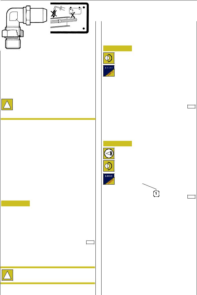
Rotating fittings
Figure 16
39306
Screw the fitting in the threaded seat provided on the pneumatic valve and lock it at the tightening torque shown in the table.
Swinging fittings
Figure 17
39307
-Check that the sealing ring (1) is into its suitable seat;
-screw the fitting till it is felt that the sealing gasket abuts onto the valve;
-adequately swing the fitting and keeping the swingable part still, lock the hexagonal nut at the tightening torque mentioned in the table.
Rotating and swinging fittings
FITTING |
TIGHTENIG TORQUE (Nm ± 10%) |
THREADING |
|
|
|
M 10 x 1.0 mm |
22 |
|
|
M 12 x 1.5 mm |
24 |
|
|
M 14 x 1.5 mm |
28 |
|
|
M 16 x 1.5 mm |
35 |
|
|
M 22 x 1.5 mm |
40 |
|
|
Base - May 2004 |
Print 603.93.321 |
STRALIS AT/AD/AS
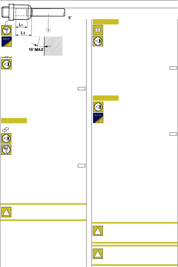
Figure 18
33977
-Use homogated pipes only;
-Check the spare pipe status, on which no cracks, cuts or nicking must be detected;
-Cut the pipe at 90° with a max 15° error with respect to the axis through the suitable pipe-cutting pliers 99387050 at the necessary length;
Figure 19
A
33976
A= Marking to identify pipe end-of-stroke
-Strongly and indelibly mark with ink two reference
notches on both diametrically-opposed pipe faces for an angle ≥ 75°, placed at the distances of L1 and L2 to guarantee a correct assembly.
Dimensions L1 and L2 change depending on the pipe
!diameter and must be measured from the longest pipe part (see Figure 18).
D |
L |
0 |
-0.5 |
-0.5 |
+0.5 |
L1 +1 |
L2 +1 |
||
(mm) |
(mm) |
(mm) |
(mm) |
|
|
|
|
|
|
6 |
19.8 |
|
17 |
22 |
|
|
|
|
|
8 |
20.5 |
|
18 |
23 |
|
|
|
|
|
12 |
25 |
|
22 |
28 |
|
|
|
|
|
16 |
27.1 |
|
24 |
30 |
|
|
|
|
|
AIR SYSTEM - BRAKES EBS 2/ESP/EBL |
23 |
Figure 20
39308
-Manually insert pipe (2) into fitting (1), with a force varying from 30 to 120 N depending on pipe diameter, so that the
notch L1 is placed inside the fitting while the notch L2 is visible.
Figure 21
33978
In case of disassembling of fittings (1) from pneumatic components, check the sealing ring (2) status, and if necessary replace it.
FITTING |
SEALING RINGS |
THREADING |
DIMENSIONS |
|
|
M 10 x 1.0 |
10.1 x 1.6 |
|
|
M 12 x 1.5 |
11.0 x 2.0 |
|
|
M 14 x 1.5 |
- |
|
|
M 16 x 1.5 |
15.0 x 2.0 |
|
|
M 22 x 1.5 |
- |
|
|
Every time a piping is detached from a quick
!connection fitting, it is necessary to replace the fitting itself. Quick connection fittings are supplied complete as spares.
Quick connection and threaded fittings, as well as
!flexible pipings used with quick connection fittings and flexible pipings used with threaded fittings, are not interchangeable.
Print 603.93.321 |
Base - May 2004 |

24 |
AIR SYSTEM - BRAKES EBS 2/ESP/EBL |
STRALIS AT/AD/AS |
|
|
|
EBS 2 (ELECTRONIC BRAKE SYSTEM)
The increase in competition in the transport sector has had the effect, among others, of constantly increasing the basic requirements of braking systems.
The introduction of the EBS electronic brake system is the logical answer to these new needs.
It is an integrated and permanent electronic control system for the brake system of the tractor and trailer. It supplements the ABS, ASR and EBL functions.
The system is made up of a pneumatic system and an electric system. In the system there is inserted the CBU (central brake unit), component integrating:
-Duplex distributor, which generates electric and pneumatic signals to increase or decrease pressure in the braking system;
-electronic central unit, which has the task of managing the braking system determining deceleration values as a function of parameters detected from various components;
-proportional relay valve, which modulates pressure at front axle.
The EBS system dialogues with the control units of the other assemblies:
Engine, Ecas, retarder and gearbox via the CAN line (VDB, Vehicle Data Bus).
EBS Benefits
Lower servicing costs.
The EBS combines many functions. The aim is to cut maintenance costs while maximizing braking safety — that is minimizing brake lining wear.
An individual control according to the lining wear parameters on both the front and rear axles harmonizes lining wear. Distributing the load homogeneously between all the brakes of the wheels reduces total consumption. In addition, the frequency of servicing and changing the linings coincide. The costs of inactivity are drastically reduced.
Depending on the servicing a vehicle needs along with other factors, the owner may be able to make considerable savings. A comparison of the maintenance costs, for the brake system, of a vehicle with EBS and one with a conventional brake system highlights significant savings.
Tractor and trailer compatibility at any time
Harmonizing the braking processes of the entire tractor-trailer combination, especially if the combinations are frequently changed, often with conventional means, is not satisfactory.
An inadequate balance, such as with a trailer whose braking is not sufficiently effective, will cause uneven wear of the brake linings.
The EBS will recognize all the incompatibilities between tractor and trailer, harmonizing braking automatically. When the brakes work in the best conditions, not only are brake maintenance costs optimized, but safety and comfort are optimum too.
Complete fault-diagnosis structures
The EBS provides the owner of the vehicle with constantly updated information on the state of the brake system and the basic brakes. This makes it possible to schedule servicing in advance. The EBS monitors all the fundamental components and functions of the brake system.
Any defect recognized by the system is accurately highlighted. The maintenance specialist can therefore rectify the error at issue.
The high degree of safety ensured by the EBS is due to several factors:
-Lower pressure accumulation and response times for the brakes on the front, rear and trailer axles.
-Better ABS function.
-Tractor/trailer always balanced in every moment.
-Constant monitoring of the service brake system. In the event of reduced brake performance, the EBS will be able to warn the driver.
-The integrated ASR function permits optimum vehicle stability and drive optimization.
Base - May 2004 |
Print 603.93.321 |
STRALIS AT/AD/AS |
AIR SYSTEM - BRAKES EBS 2/ESP/EBL |
25 |
|
|
|
OPERATING LOGIC
The purpose of the electronic control unit is to slow down the vehicle as quickly as possible, ensuring its stability and avoiding the tendency for the wheels to lock.
To achieve this aim, while braking, the electronic control unit will be informed of the:
-required deceleration via the sensors inside the duplex control valve;
-pressures made available via the pressure sensors in the components;
-reaction on slowing down due to the pressures made available via the speed sensor signals.
The continuous monitoring and processing of this information, in relation to the set aim, will cause the modulating valves to activate appropriately and optimize the braking action accordingly.
|
|
|
|
|
|
|
|
|
IN |
|
|
|
|
|
|
OUT |
|
Required deceleration |
|
|
|
|
|
|
FRONT AXLE pressure |
|
|
|
|
|
|
|
|
||
Braking pressure |
|
|
|
|
|
|
REAR AXLE pressure |
|
|
|
|
|
|
|
|
||
Wheel speed |
|
|
|
|
|
|
Graduated release trailer pressure |
|
|
|
|
|
|
|
|
|
|
|
|
|
|
|
|
|
|
|
CONTROL UNIT
AIM
n Slip = 0
BRAKE SYSTEM
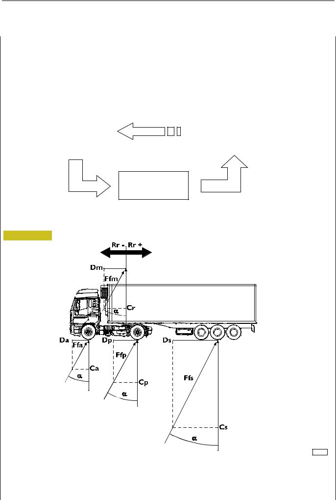
In a dynamic situation the effect on the vehicle will be managed in this way:
Figure 22
77208
Ca. Front axle load - Cp. Rear axle load - Cr. Load on fifth wheel - Da. Front axle braking force - Dp. Rear axle braking force - Dm. Braking force at graduated release - Ds. Semitrailer braking force -
Ffa. Resultant of braking/front axle load - Ffp. Resultant of braking/rear axle load - Ffm. Resultant of braking/load at graduated release - Ffs. Resultant of braking/semitrailer load - a. Braking angle - Rr. Reaction on the fifth wheel - Dec. Required deceleration - g. Acceleration due to gravity - z. Braking ratio
Print 603.93.321 |
Base - May 2004 |
26 |
AIR SYSTEM - BRAKES EBS 2/ESP/EBL |
STRALIS AT/AD/AS |
|
|
|
Generally, the EBS will tend to apply a braking force in proportion to the load on the axles, that is to maintain the same angle ”α” for all the axles:
Da |
Dp |
Ds (Dm) |
dec |
||||
|
= |
|
= |
|
= Tag α α = |
|
= z |
|
|
|
|
||||
Ca |
Cp |
Cs (Cr) |
g |
||||
Therefore, such force will be larger as compared to required deceleration.
This, as may be seen, also holds for the semitrailer control.
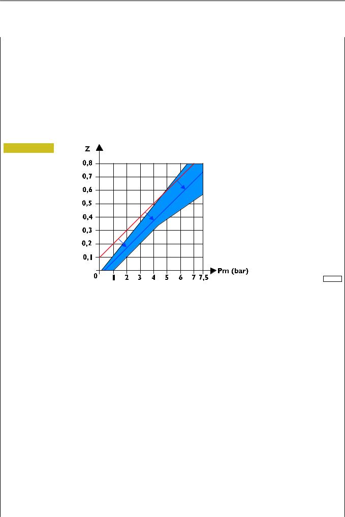
If the reaction on the fifth wheel ”Rr” is not as expected, the system automatically increases or decreases the predominance at the graduated release and ”Ffm” accordingly so as to ensure the best compatibility between the tractor and semitrailer in compliance with current type-approval standards, as may be seen in the following compatibility diagram.
Figure 23
000987t
Base - May 2004 |
Print 603.93.321 |

STRALIS AT/AD/AS |
AIR SYSTEM - BRAKES EBS 2/ESP/EBL |
27 |
|
|
|
AUXILIARY BRAKE INTEGRATION
Commercial vehicles are normally fitted with auxiliary brakes for slowing down without causing wear, such as the exhaust brake and intarder.
On vehicles equipped with the EBS, these devices can be integrated to ensure the vehicle slows down sooner and more effectively. The exhaust brake/intarder action percentage is set by the driver with the lever.
The exhaust brake will be applied up to a speed of 1000 rpm, while the action of the retarder will cause the following action depending on the position of the lever:
Figure 24
001685t
Position 0 — disengaged
Position 1 — E.B. 100%
Position 2 — E.B. 100% + Intarder 25% (20% *)
Position 3 — E.B. 100% + Intarder 50% (40% *)
Position 4 — E.B. 100% + Intarder 75% (60% *)
Position 5 — E.B. 100% + Intarder 100% (80% *)
Position 6 — E.B. 100% + Intarder 100%
These applications, always possible, will be signalled to the driver by the relevant indicator lights coming on.
*Vehicles with mechanic gearbox.
On vehicles without the optional Intarder, the auxiliary brake lever has just three positions: off, E.B. 50%, E.B. 100%.
!On vehicles fitted with a EuroTronic gearbox, with the auxiliary brake lever on position 6, slowing down will be more effective with the automatic gear shift down.
Switching the engine off for longer than one minute involving a change in load, tyres or ratios at the rear axle causes the adjustment data to be lost and so a fresh period of data acquisition will be necessary for the system to be able to reactivate auxiliary brake integration if no vehicle parameter is changed the integration will be immediately available.
If manually activating the auxiliary brakes, the next time the brake pedal is pressed will implement integration.
On releasing the brake pedal, if the manual action is compatible with the calculated action it will be kept active.
If activating the auxiliary brakes, both manual and integrated, causes the rear axle to slow down too much and a tendency for it to lock, the EBS control unit, on detecting this situation via the speed sensors, will immediately disengage them or turn on the auxiliary brake Slip Control.
Print 603.93.321 |
Base - May 2004 |
28 |
AIR SYSTEM - BRAKES EBS 2/ESP/EBL |
STRALIS AT/AD/AS |
|
|
|
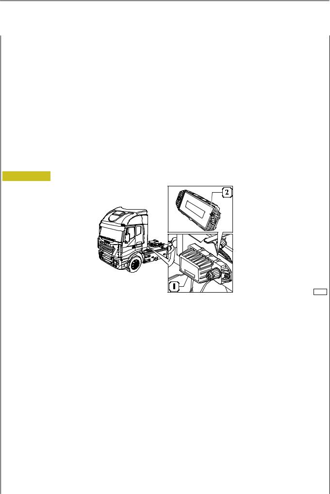
ESP (Electronic Stability Program)
ESP function, joined to EBS abilities, controls vehicle lateral dynamics.
The main objectives of this function are:
- Improving stability, most of all in both understeering and oversteering conditions
-Reducing braking spaces in change of line conditions on slippery roads Main central unit input data in order to achieve following objectives, are:
-signal from steering angle sensor (mounted on the steering wheel)
-signals from yaw speed and lateral acceleration sensors (integrated into the ESP module, that is mounted on the chassis and also contains a part of ESP software).
In order to avoid control loss, the ESP will automatically activate the brakes of one wheel per axle only trying to take the vehicle back to correct direction. In this case, the ESP controls towing body skidding angle and slant, as well as the shift between driver’s request and actual vehicle yaw speed. To the purpose of withstanding vehicle deceleration, the driving torque will be decreased. In yaw control mode, the ESP very carefully controls driver’s reactions and always tries to provide relevant support.
Note: ESP function is optionally available on tractors only.
Figure 25
89009
1. ESP module - 2. Reference pin for mounting to support bracket.
“ABS-EBL” SYSTEM (ANTI-LOCK BRAKE SYSTEM — ELECTRONIC BRAKE LIMITER)
EBL function controls rear axle wheel “skidding” by comparing it to front axle wheel speed.
On the basis of wheel r.p.m.’s and braking pressure (detected by the sensor upstream from rear axle ABS modulators), the central unit calculates vehicle speed, rear axle wheel “skidding” and minimum acceleration expected.
“ABS” (Anti-Lock Brake System)
The braking of a moving vehicle and the according deceleration and stopping distances depend above all on the grip between the surfaces of the tyres and the road.
With a fully efficient braking system, a further improvement in braking can only be achieved by acting on the friction of the tyres or on the grade of the road surface.
Even in these optimum conditions, absolute braking safety is anyhow not guaranteed when faced with especially tricky situations, such as poor grip due to a wet or icy road surface: the driver is forced to moderate use of the brakes in order to avoid partially locking one or more wheels, with the risk of skidding dangerously.
The function of the ”ABS” is therefore to ensure vehicle stability (in all braking conditions), preventing the wheels from locking irrespective of the state of the road surface, so as to ensure the available grip is made full use of.
Even in the case of emergency braking, the system makes it possible to keep direction, that is to turn the steering wheel to avoid obstacles with no risk of skidding.
In short, the anti-lock brake system (ABS):
-Prevents the wheels locking when the vehicle is braking, no matter what grip is available on the road.
-Shortens stopping distances.
-Provides safety for the driver who can keep the vehicle’s stability and direction.
Base - May 2004 |
Print 603.93.321 |
Loading...