


 Loading...
F32 TIER 3
SERIES
Industrial application
F32 MNS
F32 MNT
Technical and Repair manual

This publication provides unit and relevant component repair data, specifications, instructions and methodologies.
This publication has been drawn up for qualified and specialised personnel.
Before performing any operation check that the part relevant to the unit on which you must work is available along with all safety devices for accident-prevention, such as, goggles, helmet, gloves, shoes, etc. and hoisting and transporting equipment.
Operations are to be performed by following the indications included here, using the special equipment indicated and assuring proper repair, compliance with schedule and operator's safety requirements.
Each repair must aim to restore operating efficiency and safety in compliance with the FPT provisions.
FPT cannot be held liable for modifications, alterations or other interventions non authorised by FPT on the vehicle and if the unit is warranted the above mentioned interventions will cause its expiration.
FPT is not liable for repairing interventions.
FPT will provide further details required to carry out the interventions and all the instructions that are not included on this publication.
Data included in this publication may not be up-to-date therefore subject to Manufacturer's modifications that can be added at any time for technical or commercial purposes and also to meet new law regulations in other Countries.
If issues on this publication differ from what is actually noticed on the unit, please get in touch with the FPT network before starting any intervention”.
It is forbidden to copy this text or any of its parts and all illustrations included.
Publication edited by:
FPT - Fiat Powertrain Technologies www.fptpowertrain.com
Print P2D32F005 E - 2nd Ed. 04.2009 Revi 04.2012

F32 SERIES |
1 |
|
|
F32 SERIES
F32 Series |
Part 1 |
Print P2D32F005 E |
Base - April 2009 |

2 |
F32 SERIES |
|
|
Base - April 2009 |
Print P2D32F005 E |

F32 SERIES |
INTRODUCTION |
1 |
|
Introduction |
|
|
|
Page |
|
PREFACE . . . . . . . . . . . . . . . . . . . . . . . . . . . . . . . |
3 |
|
SYMBOLS . . . . . . . . . . . . . . . . . . . . . . . . . . . . . |
3 |
|
- Warnings . . . . . . . . . . . . . . . . . . . . . . . . . . . . . |
3 |
|
- Service operations . . . . . . . . . . . . . . . . . . . . . . |
3 |
|
GENERAL WARNINGS . . . . . . . . . . . . . . . . . . . |
5 |
|
GENERAL WARNINGS |
|
|
ON THE ELECTRIC SYSTEM . . . . . . . . . . . . . |
7 |
|
- Bonding and screening . . . . . . . . . . . . . . . . . . . |
8 |
|
CONVERSIONS BETWEEN THE MAIN UNITS |
|
|
OF MEASUREMENT OF THE INTERNATIONAL |
|
|
SYSTEM AND MOST USED DERIVED |
|
|
QUANTITIES . . . . . . . . . . . . . . . . . . . . . . . . . |
9 |
|
KEY OF LECTURE OF THE HEADINGS |
|
|
AND FOOTNOTES . . . . . . . . . . . . . . . . . . . |
10 |
Print P2D32F005 E |
Base - April 2009 |

2 |
INTRODUCTION |
F32 SERIES |
|
|
|
Base - April 2009 |
Print P2D32F005 E |
F32 SERIES |
INTRODUCTION |
3 |
|
|
|
PREFACE
Manuals for repairs are split into Parts and Sections, each one of which is marked by a numeral; the contents of these sections are indicated in the general table of contents.
The sections dealing with things mechanic introduce the specifications, tightening torque values, tool lists, assembly detaching/reattaching operations, bench overhauling operations, diagnosis procedures and maintenance schedules.
The sections (or parts) of the electric/electronic system include the descriptions of the electric network and the assembly’s electronic systems, wiring diagrams, electric features of components, component coding and the diagnosis procedures for the control units peculiar to the electric system.
Section 1 describes the engines illustrating its features and working in general. Section 2 describes the type of fuel feed.
Section 3 relates to the specific duty and is divided in four separate parts:
1.Mechanical part, related to the engine overhaul, limited to those components with different characteristics based on the relating specific duty.
2.Electrical part, concerning wiring harness, electrical and electronic equipment with different characteristics based on the relating specific duty.
3.Maintenance planning and specific overhaul.
4.Troubleshooting part dedicated to the operators who, being entitled to provide technical assistance, shall have simple and direct instructions to identify the cause of the major inconveniences.
Sections 4 and 5 illustrate the overhaul operations of the engine overhaul on stand and the necessary equipment to execute such operations.
The appendix contains a list of the general safety regulations to be respected by all installation and maintenance engineers in order to prevent serious accidents taking place.
The manual uses proper symbols in its descriptions; the purpose of these symbols is to classify contained information. In particular, there have been defined a set of symbols to classify warnings and a set for assistance operations.
SYMBOLS - Warnings
Danger for persons
Missing or incomplete observance of these prescriptions can cause serious danger for persons’ safety.
Danger of serious damage for the assembly
Failure to comply, both fully or in part, with such prescriptions will involve serious damage to the assembly and may sometimes cause the warranty to become null and void.
General danger
!
It includes the dangers of above described signals.
Environment protection
Moreover, it describes the correct actions to be taken to ensure that the assembly is used in such a way so as to protect the environment as much as possible.
NOTE It indicates an additional explanation for a piece of information.
Service operations
Example
1 |
Ø 1 |
= Seat of small end bush |
|
Close applying the required torque |
|
|
|
|
|
|
Ø 2 |
= Seat of connecting rod bearings. |
α |
Close applying the required torque + angular |
2 |
value |
|||
|
|
|
|
Print P2D32F005 E |
Base - April 2009 |

4 |
INTRODUCTION |
F32 SERIES |
|
|
|
Removal
Disconnection
Refitting
Connection
Removal
Disassembly
Fitting in place
Assembly
Tighten to torque
Tighten to torque + angle value
α
Press or caulk
Regulation
Adjustment
Visual inspection
Fitting position check
Measurement
Value to find
Check
Equipment
Surface for machining
Machine finish
Interference
Strained assembly
Thickness
Clearance
Lubrication
Damp
Grease
Sealant
Adhesive
Air bleeding
Intake
Exhaust
Operation
ρCompression ratio
Tolerance
Weight difference
Rolling torque
Rotation
Angle
Angular value
Preload
Number of revolutions
Temperature
Pressure
bar
Oversized
Higher than….
Maximum, peak
Undersized
Less than….
Minimum
Selection
Classes
Oversizing
Temperature < 0 °C
Cold
Winter
Temperature > 0 °C
Hot
Summer
Base - April 2009 |
Print P2D32F005 E |

F32 SERIES |
INTRODUCTION |
5 |
|
|
|
GENERAL WARNINGS
Warnings shown cannot be representative of all danger situations possibly occurring. Therefore, it is suggested to contact
!immediate superiors where a danger situation occurs which is not described.
Use both specific and general-purpose toolings according to the prescriptions contained in respective use and maintenance handbooks. Check use state and suitability of tools not subjected to regular check.
Manual handling of loads must be appraised beforehand, because this not only depends on the weight but also on the size and path.
Handling with mechanical means must be done with lifters that are suitable for weight, shape and volume. Hoisters, ropes and hooks used must contain clear indications on maximum carrying capacity acceptable. The use of said means is compulsorily permitted to authorised personnel only. Stay duly clear of the load, and, anyhow, never under it.
In disassembling operations, always observe provided prescriptions; prevent mechanical parts being taken out from accidentally striking workshop personnel.
Workshop jobs performed in pairs must always be performed in maximum safety; avoid operations which could be dangerous for the co-operator because of lack of visibility or of his/her not correct position.
Keep personnel not authorised to operations clear of working area.
You shall get familiar with the operating and safety instructions for the assembly prior to operating on the latter. Strictly follow all the safety indications found on the assembly.
Do not leave the running assembly unattended when making repairs.
When carrying out work on the assembly lifted off the ground, verify that the assembly is firmly placed on its supporting stands, and that the manual/automatic safety devices have been actuated in the event that the assembly is to be lifted by means of a hoist.
When you have to operate on assemblies powered by natural gas, follow the instructions contained in the document, as well as all the specific safety standards provided for.
Only remove radiator cap when the engine is cold by cautiously unscrewing it in order to let system residual pressure out.
Inflammable fuel and all inflammable fluids and liquids must be handled with care, according to what contained on harmful materials 16-point cards. Refuelling must be performed outdoors with the engine off, avoiding lit cigarettes, free flames or sparks in order to prevent sudden fires/bursts. Adequately store inflammable, corrosive and polluting fluids and liquids according to what provided by regulations in force. Compulsorily avoid to use food containers to store harmful liquids. Avoid to drill or bore pressurised containers, and throw cloths impregnated with inflammable substances into suitable containers.
Worn out, damaged or consumable parts must be replaced by original spares.
During workshop activity, always keep the work place clean; timely clear or clean floors from accidental liquid or oil spots. Electric sockets and electric equipment necessary to perform repair interventions must meet safety rules.
Print P2D32F005 E |
Base - April 2009 |

6 |
INTRODUCTION |
F32 SERIES |
|
|
|
Put on, where required by the intervention, garments and protections provided in accident prevention rules; contact with moving parts can cause serious injuries. Use suitable, preferably tight-fitted garments, and avoid to use jewels, scarves, etc.
Do not leave the engine in motion at workshop locations not provided with a pipe to scavenge exhaust gas outside.
Avoid to breathe fumes coming from heating or from paint welding because they can cause damages to health; operate outdoors or in suitably ventilated areas. Put on proper inspirator if paint powder is present.
Avoid contact with hot water or steam coming from the engine, radiator and pipings because they could cause serious burns. Avoid direct contact with liquids and fluids present in vehicle systems; where an accidental contact has occurred, refer to 16-point cards for provisions to make.
Clean the assemblies and carefully verify that they are intact prior to overhauling. Tidy up detached or disassembled parts with their securing elements (screws, nuts, etc.) into special containers.
Check for the integrity of the parts which prevent screws from being unscrewed: broken washers, dowels, clips, etc. Self-locking nuts with an insert made of nylon must always be replaced.
Avoid contact of rubber parts with diesel oil, petrol or other not compatible substances.
Before washing under pressure mechanical parts, protect electric connectors, and central units, if present.
Tightening screws and nuts must always be according to prescriptions; FPT commercial and assistance network is available to give all clarifications necessary to perform repair interventions not provided in this document.
Before welding:
-Disconnect all electronic central units, take power cable off battery positive terminal (connect it to chassis bonding) and detach connectors.
-Remove paint by using proper solvents or paint removers and clean relevant surfices with soap and water.
-Await about 15 minutes before welding.
-Equip with suitable fire resistant protections to protect hoses or other components where fluids or other materials flow which may catch fire easily on welding.
Should the vehicle be subjected to temperatures exceeding 80°C (dryer ovens), disassemble drive electronic central units.
The disposal of all liquids and fluids must be performed with full observance of specific rules in force.
Base - April 2009 |
Print P2D32F005 E |
F32 SERIES |
INTRODUCTION |
7 |
|
|
|
GENERAL WARNINGS ON THE ELECTRIC SYSTEM
If an intervention has to be made on the electric/electronic system, disconnect batteries from the system; in this case,
!always disconnect, as a first one, the chassis bonding cable from batteries negative terminal. Before connecting the batteries to the system, make sure that the system is well isolated.
Disconnect the external recharging apparatus from the public utility network before taking apparatus pins off battery terminals.
Do not cause sparks to be generated in checking if the circuit is energised.
Do not use a test lamp in checking circuit continuity, but only use proper control apparatuses.
Make sure that the electronic devices wiring harnesses (length, lead type, location, strapping, connection to screening braiding, bonding, etc.) comply with FPT system and are carefully recovered after repair or maintenance interventions.
Measurements in drive electronic central units, plugged connections and electric connections to components can only be made on proper testing lines with special plugs and plug bushes. Never use improper means like wires, screwdrivers, clips and the like in order to avoid the danger of causing a short circuit, as well as of damaging plugged connections, which would later cause contact problems.
To start up the engine, do not use fast chargers. Start up must only be performed with either separate batteries or special truck.
A wrong polarisation of supply voltage in drive electronic central units (for instance, a wrong polarisation of batteries) can cause them to be destroyed.
Disconnect the batteries from the system during their recharging with an external apparatus.
On connecting, only screw up connector (temperature sensors, pressure sensors etc.) nuts at prescribed tightening torque.
Before disconnecting the junction connector from an electronic central unit, isolate the system.
Do not directly supply electronic central units servo components at nominal vehicle voltage.
Cables must be arranged such as to result to be parallel to reference plane, i.e. as close as possible to chassis/body structure.
Once the intervention on the electric system has been completed, recover connectors and wiring harnesses according to original arrangement.
NOTE Connectors present must be seen from cable side. Connectors views contained in the manual are representative of cable side.
Print P2D32F005 E |
Base - April 2009 |

8 |
INTRODUCTION |
F32 SERIES |
|
|
|
Bonding and screening
Negative leads connected to a system bonded point must be both as short and possible and “star“-connected to each other, trying then to have their centering tidily and properly made (Figure 1, re. M).
Further, following warnings are to be compulsorily observed for electronic components:
-Electronic central units must be connected to system bonding when they are provided with a metallic shell.
-Electronic central units negative cables must be connected both to a system bonding point such as the dashboard opening bonding (avoiding “serial“ or “chain“ connections), and to battery negative terminal.
-Analog bonding (sensors), although not connected to battery negative system/terminal bonding, must have optimal isolation. Consequently, particularly considered must be parasitic resistances in lugs: oxidising, clinching defects, etc.
-Screened circuits braiding must only electrically contact the end towards the central unit entered by the signal (Figure 2).
-If junction connectors are present, unscreened section d, near them, must be as short as possible (Figure 2).
-Cables must be arranged such as to result to be parallel to reference plane, i.e. as close as possible to chassis/body structure.
Figure 1
1.NEGATIVE CABLES “STAR“ CONNECTION TO SYSTEM BONDING M
Figure 2
88039
2.SCREENING THROUGH METALLIC BRAIDING OF A CABLE TO AN ELECTRONIC COMPONENT — C. CONNECTOR d. DISTANCE ! 0
Base - April 2009 |
Print P2D32F005 E |

F32 SERIES |
INTRODUCTION |
9 |
|
|
|
CONVERSIONS BETWEEN THE MAIN UNITS OF MEASUREMENT OF THE INTERNATIONAL SYSTEM AND MOST USED DERIVED QUANTITIES
Power |
|
|
1 kW |
= |
1.36 metric HP |
1 kW |
= |
1.34 HP |
1 metric HP |
= |
0.736 kW |
1 metric HP |
= |
0.986 HP |
1 HP |
= |
0.746 kW |
1 HP |
= |
1.014 metric HP |
Torque |
|
|
1 Nm |
= |
0.1019 kgm |
1 kgm |
= |
9.81 Nm |
Revolutions per time unit |
||
1 rad/s |
= 1 rpm x 0.1046 |
|
1 rpm |
= 1 rad/s x 9.5602 |
|
Pressure |
|
|
1 bar |
= |
1.02 kg/cm2 |
1 kg/cm2 |
= |
0.981 bar |
1 bar |
= |
105 Pa |
Where accuracy is not particularly needed:
- Nm unit is for the sake of simplicity converted into kgm according to ratio 10:1
1 kgm |
= 10 Nm; |
- bar unit is for the sake of simplicity converted into kg/cm2 according to ratio 1:1
1 kg/cm2 |
= 1 bar. |
|
Temperature |
||
0° C |
= |
32° F |
1° C |
= |
(1 x 1.8 + 32) ° F |
Print P2D32F005 E |
Base - April 2009 |
10 INTRODUCTION |
|
|
|
|
|
|
F32 SERIES |
||||
|
|
|
|
|
|
|
|
|
|
|
|
KEY OF LECTURE OF THE HEADINGS AND FOOTNOTES |
|
|
|
||||||||
|
|
|
|
|
|
|
|
|
|
|
|
|
Type of |
|
Section |
|
|
Page |
|
||||
|
vehicle |
|
title |
|
|
number |
|
||||
|
|
|
|
|
|
|
|
|
|
|
|
|
|
|
|
|
|
|
|
|
|
|
|
|
|
|
|
|
|
|
|
|
|
|
|
|
|
|
|
|
|
|
|
|
|
|
|
|
|
|
|
|
|
|
|
|
|
|
|
|
|
|
|
|
|
|
|
|
|
|
|
|
|
|
|
Printout |
|
Language |
|
Basic edition referred to |
|
|
When month - year update |
|||||||||
|
|
|
|
month - year editorial |
|
|
is present (revi) to the basic |
|||||||||||
|
|
number |
|
Publication |
|
|
|
|||||||||||
|
|
|
|
phase closing |
|
|
edition |
|||||||||||
|
|
|
|
|
|
|
|
|
|
|
|
|
|
|||||
|
|
|
|
|
|
|
|
|
|
|
|
|
|
|
|
|
|
|
Base - April 2009 |
Print P2D32F005 E |

F32 SERIES |
1 |
|
|
Part 1
F32 SERIES
|
Section |
General specifications |
1 |
|
|
Fuel |
2 |
|
|
Industrial application |
3 |
|
|
Overhaul and technical specifications |
4 |
|
|
Tools |
5 |
|
|
Safety prescriptions |
Appendix |
|
|
Print P2D32F005 E |
Base - April 2009 |

2 |
F32 SERIES |
|
|
Base - April 2009 |
Print P2D32F005 E |

F32 SERIES |
3 |
|
|
UPDATING
Section |
Description |
Page |
Date of revision |
|
|
|
|
|
|
3 |
Industrial application |
21, |
64 |
January 2010 |
4 |
Mechanical overhaul |
30, |
31, 32, 33 |
April 2012 |
|
|
|
|
|
Print P2D32F005 E |
Base - April 2009 |
|
Revi 04.2012 |

4 |
F32 SERIES |
|
|
Base - April 2009 |
Print P2D32F005 E |

F32 SERIES |
SECTION 1 - GENERAL SPECIFICATIONS |
1 |
|
SECTION 1 |
|
|
General specifications |
|
|
|
Page |
|
CORRESPONDENCY BETWEEN TECHNICAL |
|
|
CODING AND COMMERCIAL CODING . . . . |
3 |
|
ENGINE VIEWS |
|
|
(for F5CE9454E*A005, F5CE9484D*A002 engines) |
. . 4 |
|
ENGINE VIEWS |
|
|
(for F5CE5454B*A004 engines) . . . . . . . . . . . . . |
5 |
|
ENGINE LUBRICATION SYSTEM . . . . . . . . . . . . . |
6 |
|
- Oil pump . . . . . . . . . . . . . . . . . . . . . . . . . . . . . |
7 |
|
- Engine oil filter . . . . . . . . . . . . . . . . . . . . . . . . . |
8 |
|
ENGINE OIL VAPOUR RECIRCULATION . . . . . . |
9 |
|
ENGINE COOLING SYSTEM . . . . . . . . . . . . . . . . . |
10 |
|
- For engines without external EGR . . . . . . . . . . |
10 |
|
- For engines with external EGR . . . . . . . . . . . . |
11 |
|
WATER PUMP . . . . . . . . . . . . . . . . . . . . . . . . . . . . |
12 |
|
THERMOSTAT . . . . . . . . . . . . . . . . . . . . . . . . . . . . |
12 |
|
- Working system . . . . . . . . . . . . . . . . . . . . . . . . |
12 |
|
HEAT EXCHANGER . . . . . . . . . . . . . . . . . . . . . . . |
13 |
|
EGR EXHAUST GAS RECYCLE SYSTEM . . . . . . . . |
14 |
|
- Internal EGR operating on the intake valves |
|
|
(for F5CE9454, F5CE9484 engines) . . . . . . . . . |
14 |
|
- Intake cam profile . . . . . . . . . . . . . . . . . . . . . . |
14 |
|
- External E.G.R. system |
|
|
(for F5CE5454 engines) . . . . . . . . . . . . . . . . . . |
15 |
|
- Working system . . . . . . . . . . . . . . . . . . . . . . . . |
15 |
|
BOOSTING . . . . . . . . . . . . . . . . . . . . . . . . . . . . . . |
16 |
|
- For engines without external EGR . . . . . . . . . . |
16 |
|
- For engines with external EGR . . . . . . . . . . . . |
17 |
Print P2D32F005 E |
Base - April 2009 |

2 |
SECTION 1 - GENERAL SPECIFICATIONS |
F32 SERIES |
|
|
|
Base - April 2009 |
Print P2D32F005 E |
F32 SERIES |
SECTION 1 - GENERAL SPECIFICATIONS |
3 |
|
|
|
CORRESPONDENCY BETWEEN TECHNICAL CODING AND COMMERCIAL CODING
Technical Code |
Commercial Code |
|
|
|
|
F5CE5454B*A004 |
F32 MNS.X |
|
|
||
F5CE9454E*A005 |
||
|
||
|
|
|
F5CE9484D*A002 |
F32 MNT.X |
|
|
|
Print P2D32F005 E |
Base - April 2009 |
4 |
SECTION 1 - GENERAL SPECIFICATIONS |
F32 SERIES |
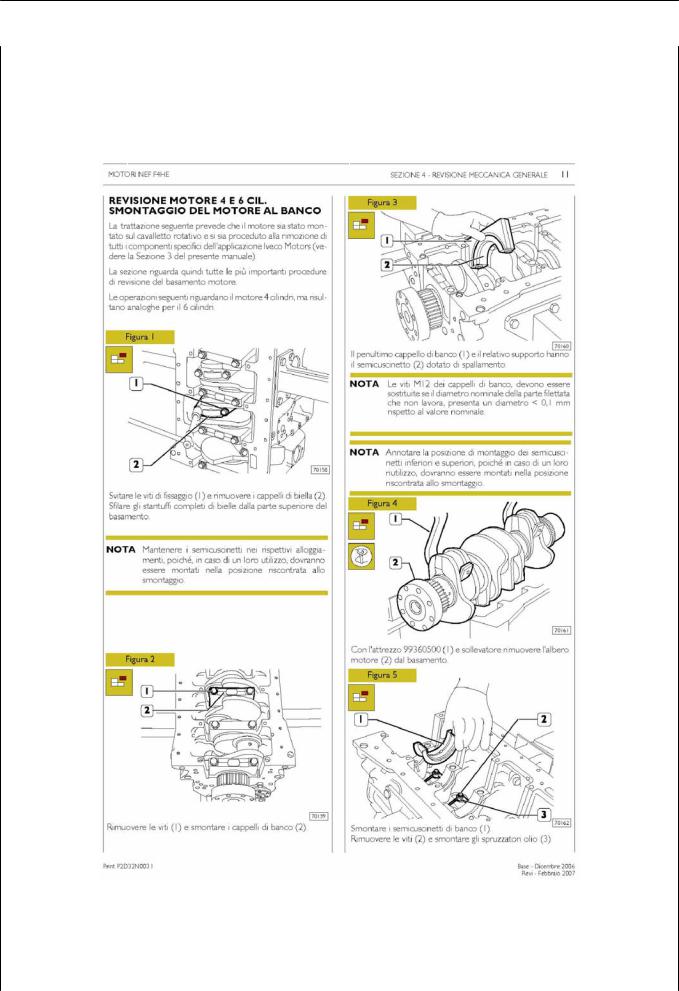
ENGINE VIEWS (for F5CE9454E*A005, F5CE9484D*A002 engines)
Figure 1
128134
Figure 2
128135
Base - April 2009 |
Print P2D32F005 E |

F32 SERIES |
SECTION 1 - GENERAL SPECIFICATIONS |
5 |
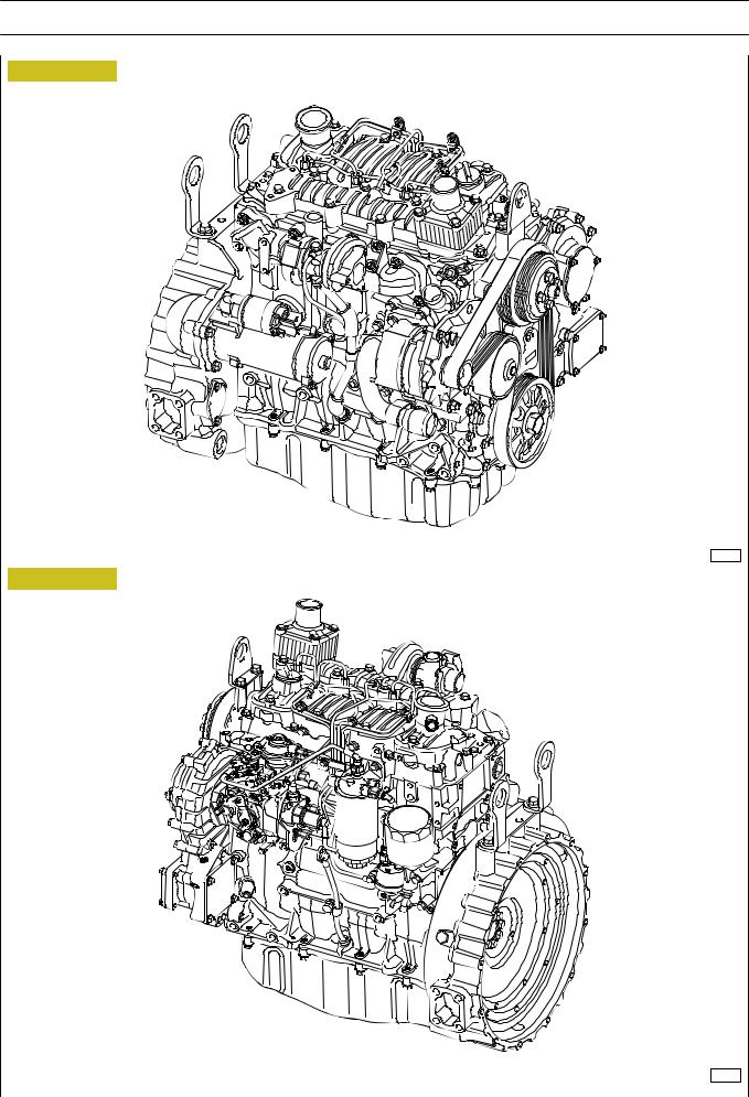
ENGINE VIEWS (for F5CE5454B*A004 engines)
Figure 3
128136
Figure 4
128137
Print P2D32F005 E |
Base - April 2009 |
6 |
SECTION 1 - GENERAL SPECIFICATIONS |
F32 SERIES |
|
|
|
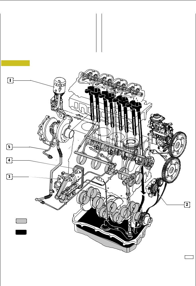
ENGINE LUBRICATION SYSTEM
Forced circulation lubrication is controlled by the rotor oil pump housed in the front part of the engine basement and driven by the toothed gear splined on the shank of the engine drive shaft.
From the oil pan, the lubrication oil is distributed to the engine drive shaft, the camshaft and the valve control.
Figure 5
The lubrication system also comprises the heat exchanger, he centrifugal blower for the versions with turbosupercharger and eventually the compressor if the compressed air system is also fitted.
All the above mentioned components vary depending on their use and therefore will be illustrated in the specific section.
Pressurized oil
Dropping oil
127695
LUBRICATION SYSTEM DIAGRAM
1.Oil filter - 2. Oil pump - 3. Heat exchanging unit - 4. Heat exchanger -
5.Turbosupercharger lubrication feed pipe
Base - April 2009 |
Print P2D32F005 E |

F32 SERIES |
SECTION 1 - GENERAL SPECIFICATIONS |
7 |
|
|
|
Oil pump
Figure 6
119405
|
PUMP SPECIFICATIONS |
|
|
|
|
Rotating speed |
|
750 rpm - 4200 rpm |
|
|
|
Feed pressure |
|
2 Bar - 4 Bar |
|
|
|
Rated flow |
|
12.2 l/min - 75.9 l/min |
|
|
|
Oil type |
|
SAE 20/30 |
|
|
|
Max. oil temperature |
|
80 °C |
|
|
|
1.Main gear - 2. Secondary gear - 3. Pump unit - 4. Drive shaft - 5. Secondary shaft
6.Cover - 7. Internal rotor - 8. External rotor - 9. Bush.
Print P2D32F005 E |
Base - April 2009 |
8 |
SECTION 1 - GENERAL SPECIFICATIONS |
F32 SERIES |
|
|
|
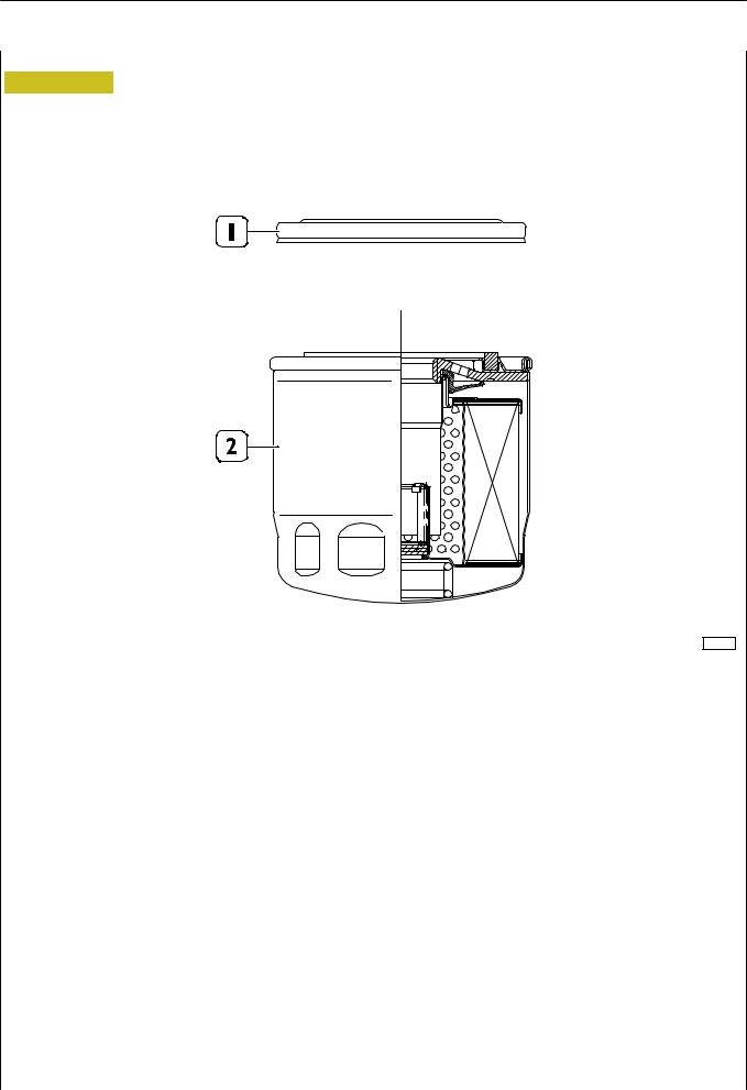
Engine oil filter
Figure 7
119406
|
1. Protective cover - 2. Cartridge |
Booster pressure: |
20 bar (ISO 4548/3) |
Dynamic pressure: |
0-15 bar (1Hz) > 50,000 cycles (ISO 4548/5) |
Operating temperature: |
-40 / + 140 ˚C |
Torque wrench setting: |
32.5 ± 2.5 Nm |
Maximum flow: |
50 l/min. |
Load loss at the end of life cycle: |
2.5 bar |
Accumulation: |
> 15 gr with 2.5 bar load loss (ISO 16889) |
Base - April 2009 |
Print P2D32F005 E |
F32 SERIES |
SECTION 1 - GENERAL SPECIFICATIONS |
9 |
|
|
|
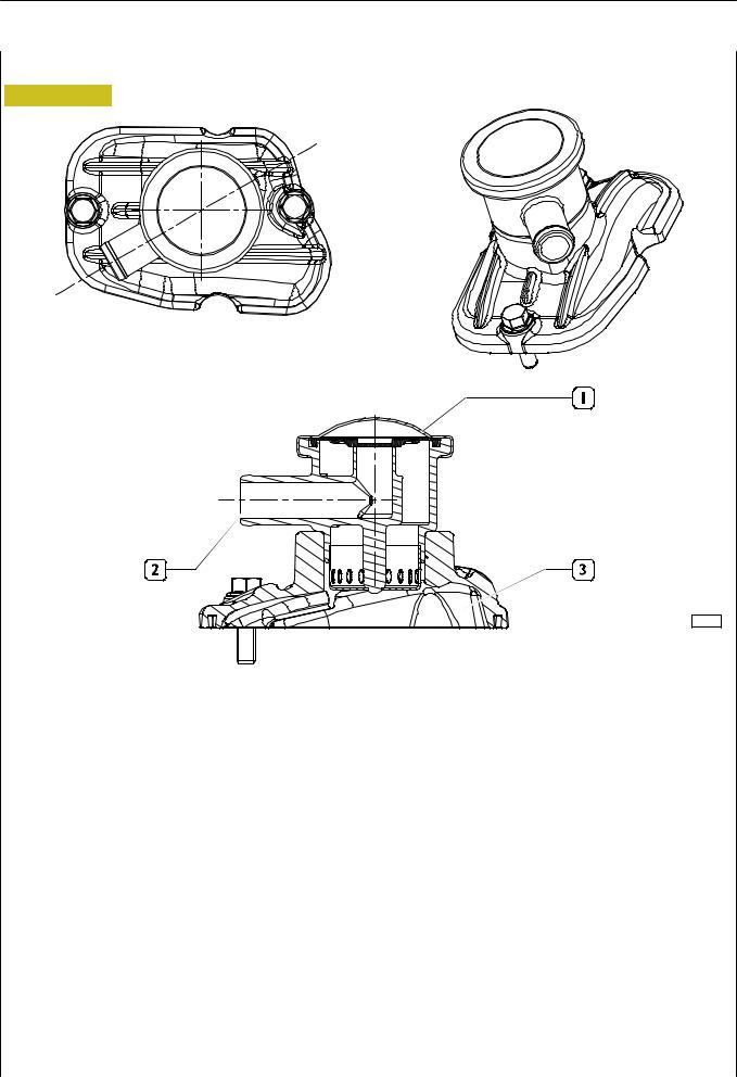
ENGINE OIL VAPOUR RECIRCULATION
Figure 8
119407
1. Valve - 2. Breather - 3. Tappet cover
On the tappet cover (3) there is a valve (1) having the duty to cause condensation of oil vapours making them drop by gravity on the underlying tappet cover (3).
The remaining non condensed vapours will be duly conveyed through the breather (2), for instance by suction (appropriate connection must be provided by the outfitter).
Print P2D32F005 E |
Base - April 2009 |
10 |
SECTION 1 - GENERAL SPECIFICATIONS |
F32 SERIES |
|
|
|
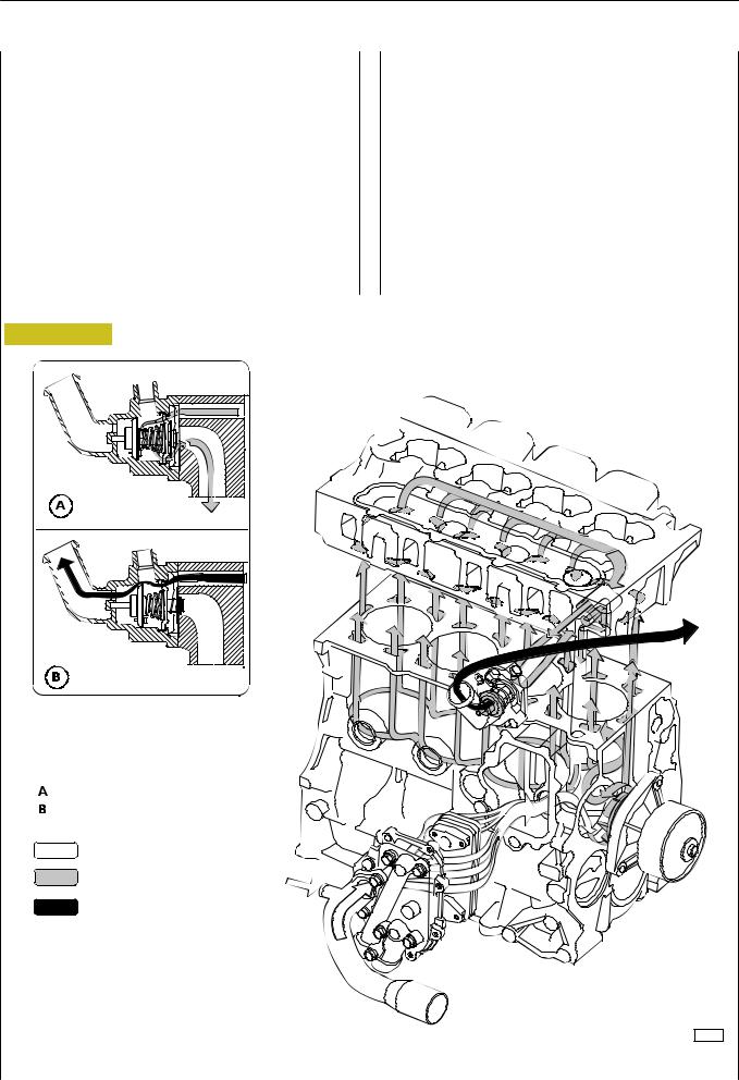
ENGINE COOLING SYSTEM
For engines without external EGR
The closed circuit forced circulation engine cooling system is composed of the following parts:
-expansion tank: position, form and dimensions may vary depending on the engine fitting;
-radiator dissipating the heat absorbed by the engine cooling liquid. This component’s position and dimensions may vary depending on the outfit;
-fan increasing the radiator’s cooling power. This component may vary depending on the specific engine fitting;
Figure 9
-heat exchanger cooling the lubricant oil. This component may vary depending on the specific engine fitting;
-centrifugal water pump positioned in the front part of the engine basement;
-thermostat controlling cooling liquid circulation.
Closed thermostat
Open thermostat
Water inflow
Engine cooling water
Water outflow from thermostat
120018
ENGINE COOLING SYSTEM DIAGRAM
Base - April 2009 |
Print P2D32F005 E |
F32 SERIES |
SECTION 1 - GENERAL SPECIFICATIONS 11 |
|
|
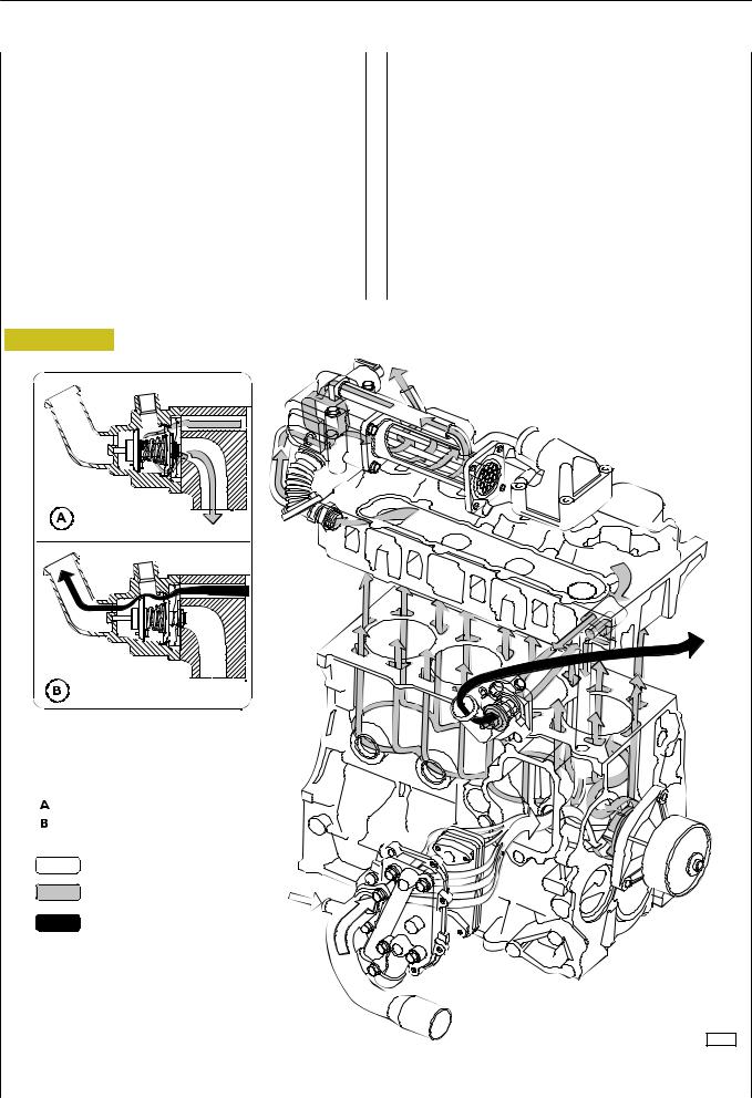
For engines with external EGR
The closed circuit forced circulation engine cooling system is composed of the following parts:
-expansion tank: position, form and dimensions may vary depending on the engine fitting;
-radiator dissipating the heat absorbed by the engine cooling liquid. This component’s position and dimensions may vary depending on the outfit;
-fan increasing the radiator’s cooling power. This component may vary depending on the specific engine fitting;
Figure 10
-heat exchanger cooling the lubricant oil. This component may vary depending on the specific engine fitting;
-centrifugal water pump positioned in the front part of the engine basement;
-thermostat controlling cooling liquid circulation.
Closed thermostat
Open thermostat
Water inflow
Engine cooling water
Water outflow from thermostat
118983
ENGINE COOLING SYSTEM DIAGRAM
Print P2D32F005 E |
Base - April 2009 |
12 |
SECTION 1 - GENERAL SPECIFICATIONS |
F32 SERIES |
|
|
|
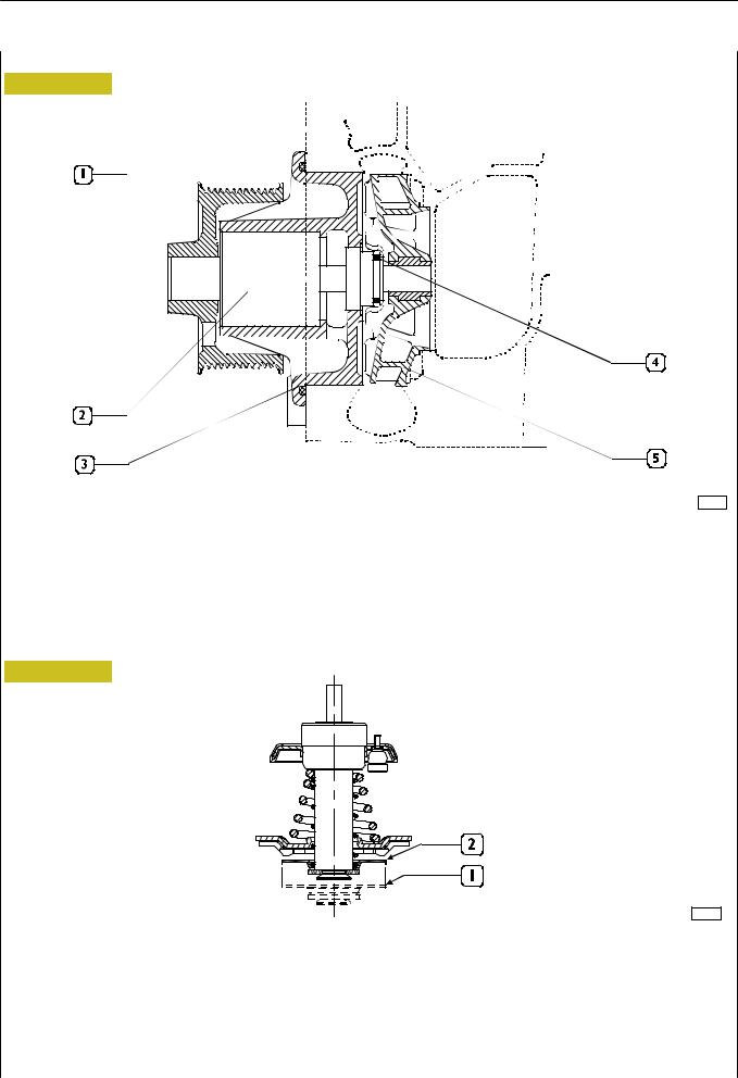
WATER PUMP
Figure 11
120047
WATER PUMP SECTION
1. Hub - 2. Shaft with bearing - 3. Pump unit - 4. Sheath - 5. Impeller.
The water pump is a centrifugal blade turbine type pump. The pump’s bearing (2) is connected to the impeller’s shaft as a whole. Water tight between the pump unit (3) and the shaft (2) is ensured by the sheath (4).
THERMOSTAT
Figure 12
119412
THERMOSTAT DIAGRAM
Working system
When the engine is cool, water output from the front part of the cylinder head flows into an inlet containing the thermostat, which cuts out water circulation to the radiator. This way, water circulation will only be possible in the pump-engine circuit, insofar allowing engine heat-up quickly. The thermostat valve starts opening at nearly 80 ˚C, allowing water circulation into the radiator and also obstructing direct return towards the engine. Check the thermostat efficiency and replace it in case of doubtful functioning.
1.Stroke starts at 79˚ ± 2 ˚C
2.7 mm stroke at 94˚±2˚C
Base - April 2009 |
Print P2D32F005 E |
Loading...