


 Loading...
ASSEMBLY GUIDE
60" Espresso TV Stand
NS-HF2003
Before using your new product, please read these instructions to prevent any damage.

Contents
Introduction . . . . . . . . . . . . . . . . . . . . . . . . . . . . . . . . . . . . . . . . . . . . . . . . . . . . . . . . . . . . . . . . . . . . . . . . . . . . . . . . . . . . . . . . . . 3 IMPORTANT SAFETY INSTRUCTIONS . . . . . . . . . . . . . . . . . . . . . . . . . . . . . . . . . . . . . . . . . . . . . . . . . . . . . . . . . . . . . . . . . . . 3 Features . . . . . . . . . . . . . . . . . . . . . . . . . . . . . . . . . . . . . . . . . . . . . . . . . . . . . . . . . . . . . . . . . . . . . . . . . . . . . . . . . . . . . . . . . . . . . . 3
Dimensions. . . . . . . . . . . . . . . . . . . . . . . . . . . . . . . . . . . . . . . . . . . . . . . . . . . . . . . . . . . . . . . . . . . . . . . . . . . . . . . . . . . . . . . . . . . . . . . . . . . . . . . 3
Tools needed . . . . . . . . . . . . . . . . . . . . . . . . . . . . . . . . . . . . . . . . . . . . . . . . . . . . . . . . . . . . . . . . . . . . . . . . . . . . . . . . . . . . . . . . . 4 Package contents . . . . . . . . . . . . . . . . . . . . . . . . . . . . . . . . . . . . . . . . . . . . . . . . . . . . . . . . . . . . . . . . . . . . . . . . . . . . . . . . . . . . . 4
Stand parts . . . . . . . . . . . . . . . . . . . . . . . . . . . . . . . . . . . . . . . . . . . . . . . . . . . . . . . . . . . . . . . . . . . . . . . . . . . . . . . . . . . . . . . . . . . . . . . . . . . . . . . 4 Stand hardware. . . . . . . . . . . . . . . . . . . . . . . . . . . . . . . . . . . . . . . . . . . . . . . . . . . . . . . . . . . . . . . . . . . . . . . . . . . . . . . . . . . . . . . . . . . . . . . . . . . 5 Anti-tip safety kit . . . . . . . . . . . . . . . . . . . . . . . . . . . . . . . . . . . . . . . . . . . . . . . . . . . . . . . . . . . . . . . . . . . . . . . . . . . . . . . . . . . . . . . . . . . . . . . . . 5 Pre-assembled hardware. . . . . . . . . . . . . . . . . . . . . . . . . . . . . . . . . . . . . . . . . . . . . . . . . . . . . . . . . . . . . . . . . . . . . . . . . . . . . . . . . . . . . . . . . . 5
Installation tips . . . . . . . . . . . . . . . . . . . . . . . . . . . . . . . . . . . . . . . . . . . . . . . . . . . . . . . . . . . . . . . . . . . . . . . . . . . . . . . . . . . . . . . 6
Installing dowels. . . . . . . . . . . . . . . . . . . . . . . . . . . . . . . . . . . . . . . . . . . . . . . . . . . . . . . . . . . . . . . . . . . . . . . . . . . . . . . . . . . . . . . . . . . . . . . . . . 6 Installing cam locks and cam screws. . . . . . . . . . . . . . . . . . . . . . . . . . . . . . . . . . . . . . . . . . . . . . . . . . . . . . . . . . . . . . . . . . . . . . . . . . . . . . . 6
Assembly instructions. . . . . . . . . . . . . . . . . . . . . . . . . . . . . . . . . . . . . . . . . . . . . . . . . . . . . . . . . . . . . . . . . . . . . . . . . . . . . . . . . 7
STEP 1 - Install the dowels and cam screws. . . . . . . . . . . . . . . . . . . . . . . . . . . . . . . . . . . . . . . . . . . . . . . . . . . . . . . . . . . . . . . . . . . . . . . . . 7 STEP 2 - Assemble the left side and middle panels. . . . . . . . . . . . . . . . . . . . . . . . . . . . . . . . . . . . . . . . . . . . . . . . . . . . . . . . . . . . . . . . . . 9 STEP 3 - Attach the right side and bottom panels. . . . . . . . . . . . . . . . . . . . . . . . . . . . . . . . . . . . . . . . . . . . . . . . . . . . . . . . . . . . . . . . . . 10 STEP 4 - Attach the feet.. . . . . . . . . . . . . . . . . . . . . . . . . . . . . . . . . . . . . . . . . . . . . . . . . . . . . . . . . . . . . . . . . . . . . . . . . . . . . . . . . . . . . . . . . . 11 STEP 5 - Attach the top panel. . . . . . . . . . . . . . . . . . . . . . . . . . . . . . . . . . . . . . . . . . . . . . . . . . . . . . . . . . . . . . . . . . . . . . . . . . . . . . . . . . . . . 12 STEP 6 - Attach the back panel. . . . . . . . . . . . . . . . . . . . . . . . . . . . . . . . . . . . . . . . . . . . . . . . . . . . . . . . . . . . . . . . . . . . . . . . . . . . . . . . . . . . 13 STEP 7 - Attach the trim to the shelf. . . . . . . . . . . . . . . . . . . . . . . . . . . . . . . . . . . . . . . . . . . . . . . . . . . . . . . . . . . . . . . . . . . . . . . . . . . . . . . 14 STEP 8 - Assemble the drawers.. . . . . . . . . . . . . . . . . . . . . . . . . . . . . . . . . . . . . . . . . . . . . . . . . . . . . . . . . . . . . . . . . . . . . . . . . . . . . . . . . . . 15 STEP 9 - Insert the drawers and shelf. . . . . . . . . . . . . . . . . . . . . . . . . . . . . . . . . . . . . . . . . . . . . . . . . . . . . . . . . . . . . . . . . . . . . . . . . . . . . . 18 STEP 10 - Attach the door.. . . . . . . . . . . . . . . . . . . . . . . . . . . . . . . . . . . . . . . . . . . . . . . . . . . . . . . . . . . . . . . . . . . . . . . . . . . . . . . . . . . . . . . . 20
Anti-tip safety strap installation instructions . . . . . . . . . . . . . . . . . . . . . . . . . . . . . . . . . . . . . . . . . . . . . . . . . . . . . . . . . . 21 ONE-YEAR LIMITED WARRANTY . . . . . . . . . . . . . . . . . . . . . . . . . . . . . . . . . . . . . . . . . . . . . . . . . . . . . . . . . . . . . . . . . . . . . . 22
2 |
www.insigniaproducts.com |

NS-HF2003
Introduction
Congratulations on your purchase of a high-quality Insignia product. Your NS-HF2003 represents the state of the art in TV stand design and is designed for reliable and trouble-free performance.
IMPORTANT SAFETY INSTRUCTIONS
WARNING: Failure to follow these installation instructions or any other abuse, mistreatment, unreasonable use, or neglect of the product shall constitute a waiver of all warranties, expressed and implied, and constitute a waiver of all claims of liability (including loss of revenue or income, pain and suffering, emotional distress, or similar damages), incidental, punitive, or consequential damages arising out of or resulting from the improper installation, abuse, mistreatment, unreasonable use, or neglect regardless of whether such damages arise in contract, tort, under statute, in equity, at law, or otherwise.
WARNING: THIS PRODUCT IS INTENDED TO HOLD THE MAXIMUM WEIGHT (EVENLY DISTRIBUTED) INDICATED. EXCEEDING THE MAXIMUM WEIGHT WILL RESULT IN INSTABILITY AND MAY CAUSE POSSIBLE INJURY.
WARNINGS:
•The weight of your TV must not exceed 120 lbs. (54.4 kg).
•This product contains small items that could be a choking hazard if swallowed. Keep these items away from young children!
SAVE THESE INSTRUCTIONS
Features
•Supports TVs up to 65" (165.1 cm) and 120 lbs. (54.4 kg)
•Rich dark espresso finish fits your décor
•Two drawers for hiding movies, games, remotes, and more
•Sliding glass door lets you operate AV devices remotely
•Adjustable shelf accommodates most equipment
•Cord cutout provides easy cable routing
Dimensions
|
|
|
) |
|
|
.4 |
cm |
|
52 |
|
|
"(1 |
|
|
|
60 |
|
|
|
1 |
|
8 |
|
. |
|
5 |
|
" |
|
|
( |
|
4 |
|
6 |
|
. |
|
9 |
|
c |
|
m |
|
) |
22" (55.8 cm)
25 lbs (11.3 kg)
120 lbs (54.4 kg)
|
|
|
) |
|
|
.2 cm |
|
|
8" (20 |
|
|
|
|
|
) |
|
|
3.2 |
cm |
|
"(7 |
|
|
.8 |
|
|
|
28 |
|
|
|
50 lbs (22.7 kg)
8.3" (21 cm)
50 lbs (22.7 kg)
6.6 × 26.9 × 13.4"
(16.8 × 68.3 × 34 cm) (H × W × D)
www.insigniaproducts.com |
3 |

60" Espresso TV Stand
Tools needed
You need the following tools to assemble your new TV stand:
Phillips screwdriver Flathead screwdriver
Rubber mallet
Package contents
Make sure that you have all the parts and hardware necessary to assemble your new TV stand.
Stand parts
F r o n t
6 Left side panel (1)
Top
11 Front trim (1)
1 Top panel (1)
3 Back panel (1)
7 Middle panel (1)
12 Adjustable shelf (1)
2 Bottom panel (1)
4 Upper crossbar (1)
5 Middle crossbar (1)
|
9 Side |
10 Middle |
|
|
foot (1) |
||
8 Right side panel (1) |
foot (4) |
||
|
|||
|
|
13 Back drawer panel (2)
14 Left drawer panel (2)
15 Right drawer panel (2) |
17 Bottom drawer |
support (2) |
16 Bottom drawer panel (2)
18 Front drawer panel (2)
19 Door (1)
4 |
www.insigniaproducts.com |

NS-HF2003
Stand hardware
Note: You may not use all the included hardware.
LABEL |
HARDWARE |
QTY. |
A |
Glue |
1 |
B |
|
16 |
|
Large wood dowel (WD830) |
|
C |
Cam screw (CSST8833BL) |
21 |
|
||
D |
Large cam lock (CL1512BL) |
11 |
E |
Small wood dowel (WD630) |
6 |
F |
Small cam lock (CL1410BL) |
10 |
G |
Wood screw 3.5 × 12 × 6 mm (RHWS35126BL) |
2 |
|
|
|
H |
Wood screw 4 × 50 × 8 mm (FHWS4508BL) |
6 |
|
|
LABEL |
HARDWARE |
QTY. |
I |
|
16 |
Wood screw 4 × 32 × 8 mm (FHWS4328BL)
J |
|
8 |
|
Allen bolt 6 × 50 × 10 mm (AB65010BL) |
|
K |
Allen wrench |
1 |
L |
|
23 |
Wood screw 3 × 16 × 8 mm (RHWS3168BL)
M |
|
2 |
|
Wire management strip |
|
N |
Handle |
2 |
O |
Machine screw 4 × 21 × 8 mm (MS4218BL) |
4 |
|
|
|
P |
Shelf pin |
4 |
Anti-tip safety kit
WA |
Wood Screw 4 × 32 × 8 mm (RHWS4328BL) |
2 |
|
|
|
WB |
Plastic socket |
2 |
WC |
Mounting tab |
4 |
|
||
WD |
Plastic mounting strap |
2 |
Pre-assembled hardware
These parts are pre-assembled and attached to other parts. They are shown here for reference only. |
|
|||
|
Roller |
2 |
|
4 sets |
ZA |
|
ZD |
||
|
|
|
Drawer glides (2 pieces per set) |
|
ZB |
Latch |
2 |
ZE |
5 |
|
|
|
Floor leveler |
|
ZC |
Wood screw 3.5 × 12 × 6 mm (FHWS35126BL) |
16 |
ZF |
24 |
|
|
Wood screw 3.5 × 12 × 6 mm (RHWS35126BL) |
|
|
|
|
|
|
|
www.insigniaproducts.com |
5 |
60" Espresso TV Stand
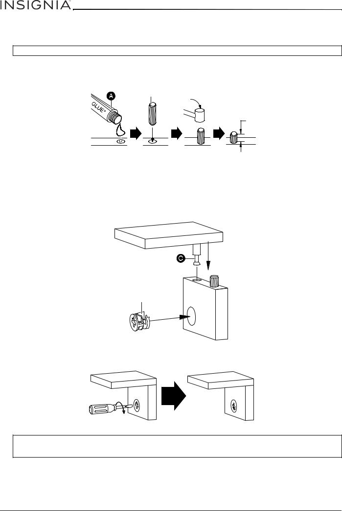
Installation tips
Installing dowels
CAUTION: Make sure that you use glue with the dowels. The glue helps stabilize your TV stand and keeps it from coming apart.
1Put a drop of glue (A) in the dowel hole, then insert about 2/3 of the dowel (B or E) into the hole. You can tap the dowel with a rubber mallet, if necessary.
2After the dowel is installed, wipe off the excess glue with a damp cloth.
 OR
OR 
1/3
Installing cam locks and cam screws
One end of a cam screw (C) is threaded, the other end is not. The un-threaded end locks into a cam lock (D or F).
1Screw the threaded end of the cam screw (C) into the cam screw hole.
2Insert a cam lock (D or F) into a cam lock hole. Make sure that the open end in the cam lock faces toward the cam screw hole.
3Insert the un-threaded end of a cam screw (C) into the opening in the cam lock.
 OR
OR 
4Use a flat blade screwdriver to turn the cam lock clockwise until the arrow and the + and – symbols point away from the connected panel.
CAUTIONS:
•Do not use an automatic screwdriver to tighten the cam locks.
•Do not over-tighten the cam locks.
6 |
www.insigniaproducts.com |

NS-HF2003
Assembly instructions
WARNING: You need two people to assemble your TV stand.
STEP 1 - Install the dowels and cam screws.
You’ll need
A Glue (1) |
C Cam screw (21) |
E Small wood dowel (6) |
B Large wood dowel (16)
Rubber mallet
1Put a drop of glue in each dowel hole, then insert about 2/3 of each dowel (B or E) into the hole. Use a rubber mallet, if needed. Install the dowels (as shown). For more information see Installing dowels on page 6.
2Screw the cam screws (C) into the cam screw holes (as shown). For more information, see Installing cam locks and cam screws on page 6.
Top panel (1)
Middle crossbar (5)
Left side panel (6)
www.insigniaproducts.com |
7 |
Loading...