


 Loading...
USER GUIDE
Wood Finish and Glass 3-in-1 TV Stand
for TVs up to 52”/135 lbs.
NS-3IN1MT50C/NS-3IN1MT50C-C
SAFETY INFORMATION AND SPECIFICATIONS .2 |
|
PACKAGE CONTENTS: PARTS .................................. |
4 |
PACKAGE CONTENTS: HARDWARE ....................... |
5 |
ASSEMBLY INSTRUCTIONS ...................................... |
7 |
CARE AND MAINTENANCE ................................... |
29 |
Before using your new product, please read these instructions to prevent any damage.
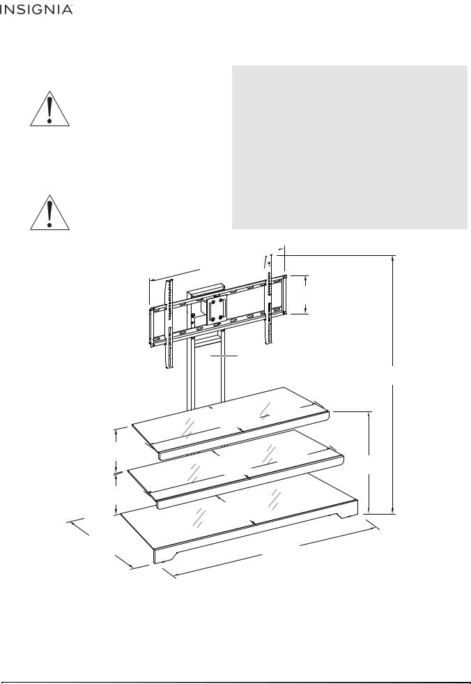
SAFETY INFORMATION AND SPECIFICATIONS
CAUTION: The top surface of this stand is designed for use with a product weighing no more than
135 lbs. (61.2 kg) and having a width that permits it to sit evenly on the
stand with no more than a one-inch overhang on each side of the shelf. Use with products that weigh more than the maximum weight allowed, or with dimensions that extend beyond the maximum width may result in instability, which may result in injury.
CAUTION: This product contains small items that could be a choking hazard if swallowed.
Keep these items away from young children!
3-in-1 TV STAND
Maximum overall weight: 235 lbs (106.6 kg) Maximum top shelf weight: 135 lbs (61.2 kg) Maximum lower shelf weight: 50 lbs (22.6 kg)
Maximum screen size: 52” diagonal (50” width) side of the top shelf
Overall dimensions (H × W × D):
55 × 48 × 21.1 in. (139.7 x 122 x 53.6 cm)
32 inch  (81.3 cm)

8.7 inch
(22.2 cm)
9.3 inch
(23.5 cm)
9.3 inch
(23.5 cm)
21.1 inch
(53.6 cm)
Long support: 48” high (122 cm)
Back frame: 21.7” high (55.2 cm)
55 inch
(139.7 cm)
 40 inch 15 inch (101.6 cm) (38 cm)
|
44 inch |
|
16.3 inch |
(111.8 cm) |
22 inch |
(41.4 cm) |
|
(55.9 cm) |
18.8 inch
(47.8 cm)
48 inch
(122 cm)
2 |
www.insigniaproducts.com |

3-in-1 TV STAND
Tools needed:
Phillips screwdriver
Edge-to-edge stud finder |
Power drill |
|
Level
Hammer
1/2” Socket wrench
Pencil
3/8” drill bit (for tipping restraint)
3/16” wood drill bit or
7/16” masonry drill bit
www.insigniaproducts.com |
3 |

3-in-1 TV STAND
PACKAGE CONTENTS: PARTS
Make sure that you have all the parts necessary to assemble your new TV stand.
A Left side frame (1)
B Right side frame (1) |
C Short back frame (1) |
E Top crossbar (1)
D Long rear support (1)
F Top stringer (1)
G Middle crossbar (1)
H Middle stringer (1)
I Bottom brace (1)
J Bottom stringer (1)
K Top glass (1)
L Middle glass shelf (1)
M Bottom glass shelf (1)
N Swivel bracket (1) |
Q TV bracket (2) |
|
P Mounting frame (1)
4 |
www.insigniaproducts.com |

3-in-1 TV STAND
PACKAGE CONTENTS: HARDWARE
Note: You may receive extra hardware.Note: You may receive extra hardware.
Make sure that you have all the hardware necessary to assemble your new TV stand.
Label |
Hardware |
Qty. |
R |
Cable clip |
2 |
|
||
S |
Suction cup |
19 |
T |
Bolt 3/4” (19.05 |
8 |
|
mm) |
|
U |
Bolt 1 3/8” |
4 |
|
(34.92 mm) |
|
|
Bolt 1 5/8” |
|
V |
(41.27 mm) |
8 |
|
Bolt 2 1/4” (57.15 mm)
W |
12 |
Label |
Hardware |
Qty. |
X |
Lock washer |
32 |
Y |
Flat washer |
36 |
Z |
Hex nut |
8 |
AA |
Lag bolt |
4 |
BB |
Large flat washer |
4 |
CC |
Concrete anchor |
4 |
DD |
Open wrench |
1 |
EE |
|
2 |
|
Allen (hex) wrench 0.158” (4 mm) |
|
FF |
Touch-up pen |
1 |
|
|
www.insigniaproducts.com |
5 |

3-in-1 TV STAND
PACKAGE CONTENTS: HARDWARE (continued)
Label |
Hardware |
Qty. |
GG |
|
1 |
|
Tipping restraint hardware kit |
|
HH |
Bolt M4 × 12 mm |
4 |
II |
Bolt M4 × 30 mm |
4 |
JJ |
Bolt M5 × 12 mm |
4 |
KK |
Bolt M5 × 30 mm |
4 |
LL |
Bolt M6 × 12 mm |
4 |
MM |
Bolt M6 × 35 mm |
4 |
|
|
|
NN |
Bolt M8 × 16 mm |
4 |
PP |
Bolt M8 × 40 mm |
4 |
|
|
Label |
Hardware |
Qty. |
Lock washer M4 |
4 |
|
RR |
Lock washer M5 |
4 |
SS |
Lock washer M6 |
4 |
TT |
Lock washer M8 |
4 |
UU |
Large spacer |
4 |
VV |
Small spacer |
4 |
WW |
Flat washer M4/M5 |
8 |
XX |
Flat washer M6/M8 |
4 |
Sellpoints Video Instruction Guide
Go to http://vig.sellpoints.com/insignia/default/ISGBBY00001.html to view step-by-step instructional videos for assembling and installing your product.
1 |
|
|
|
2 |
|
|
|
3 |
|
|
|
|
|
|
4in |
|||||||||||||||||
|
|
|
|
|
|
|
|
|
|
|
|
|
|
|
|
|
|
|
|
|
|
|
|
|
|
|
|
|
|
|
|
|
|
|
|
|
|
|
|
|
|
|
|
|
|
|
|
|
|
|
|
|
|
|
|
|
|
|
|
|
|
|
|
|
|
|
|
|
|
|
|
|
|
|
|
|
|
|
|
|
|
|
|
|
|
|
|
|
|
|
|
|
|
|
|
|
|
|
10 |
20 |
30 |
40 |
50 |
60 |
70 |
80 |
90 |
100mm |
6 www.insigniaproducts.com

3-in-1 TV STAND
ASSEMBLY INSTRUCTIONS
Step 1: Align and attach the left and right side frames (A and B) to the back frame (C)
Caution: Assemble your stand on a carpeted floor or the empty carton to avoid scratching your stand.
1Insert two 1 3/8" bolts (U) through both lock washers (X) and flat washers (Y) through the drilled holes on the left side frame (A) and screw into the threaded holes on the side of the short back frame (C).
2Repeat the same procedure to attach the right side frame (B).
NOTE: Do not fully tighten all bolts until you finish assembling all parts. Once assembled, go back and fully tighten all bolts. This will make the assembly easier.
UP
You’ll need:
U (4) X (4) Y (4) EE (1)
www.insigniaproducts.com |
7 |

3-in-1 TV STAND
Step 2: Align and attach the upper and middle crossbars (E and G) and the bottom brace (I) to the side frames (A and B)
1Insert two 1 5/8” bolts (V) through the lock washers (X) and flat washers (Y) through the drilled holes on the top rail of the side frames (A and B) and securely screw into the threaded holes of the top crossbar (E).
2 Repeat the same procedure to attach the middle crossbar (G) to the middle rail of the side frames (A and B).
3Insert two 2¼” bolts (W) through the lock washers (X) and flat washers (Y) through the drilled holes on the bottom rail of the side frames (A and B) and securely screw into the threaded holes of the bottom brace (I).
UP
You’ll need:
V (4) |
X (6) |
Y (6) |
EE (1) |
W (2) |
|
|
|
|
|
|
8 www.insigniaproducts.com
3-in-1 TV STAND
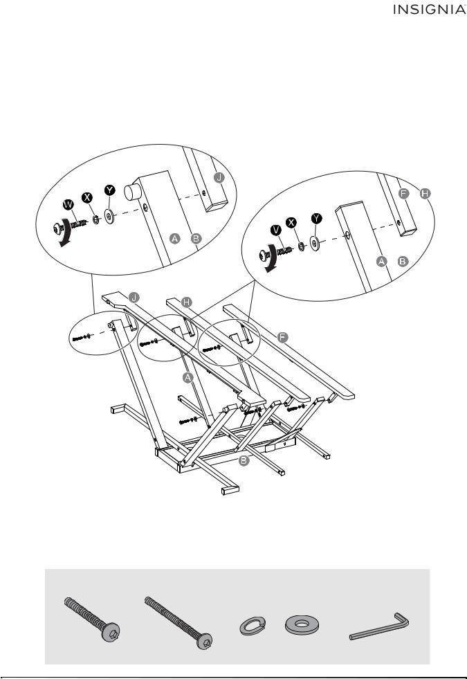
Step 3: Align and attach the front stringers (F, H, and J) to the front of the side frames (A and B)
1Insert two 1 5/8” bolts (V) through the lock washers (X) and flat washers (Y) through the drilled holes on the top rail of the side frames (A and B) and securely screw into the threaded holes of the top stringer (F).
2 Repeat the same procedure to attach the middle stringer (H) to the middle rail of the side frames (A and B).
3Insert two 2¼” bolts (W) through the lock washers (X) and flat washers (Y) through the drilled holes on the bottom rail of the side frames (A and B) and securely screw into the threaded holes of the bottom stringer (J).
You’ll need:
V (4) |
X (6) |
Y (6) |
EE (1) |
W (2) |
|
|
|
|
|
|
www.insigniaproducts.com |
9 |

3-in-1 TV STAND
Step 4: Leveling the stand
Stand the assembled frame upright. Adjust the levelers on the side frames (A and B) to level the assembly.
NOTE: For swivel stand assembly, see “SWIVEL STAND ASSEMBLY INSTRUCTIONS” on page 22. For Wall Mount or Table Top assembly, continue to the next step.
10 |
www.insigniaproducts.com |
Loading...