


XE-145M
80448905
Revision A
January 2016
Save These Instructions
Compressor Control System
Instruction Manual
Model Xe-145M Reciprocating Compressors
Anleitungshandbuch
DE
Manuel d’instructions
FR
Käyttöopas
FI
Kasutusjuhend
ET
Instructiehandleiding
NL
Instruktionsmanual
DA
Návod k obsluze
CS
Ръководство за употреба
BG
Instruction Manual
EN
Εγχειρίδιο Οδηγιών
EL
Kezelői kézikönyv
HU
Ekspluatācijas rokasgrāmata
LV
Instruktionsmanual
SV
Manual de instrucciones
ES
Priročnik z navodili
SL
Návod na použitie
SK
Manual de utilizare
RO
Manual de Instruções
PT
Instrukcja obsługi
PL
Instruksjonsmanual
NO
Instrukcijų vadovas
LT
Kullanım Kılavuzu
TU
说明手册
ZH
Manuale di istruzioni
IT
Инструкция по эксплуатации
RU

EN
2 80448905 Rev A
SAFETY INFORMATION . . . . . . . . . . . . . . . . . . . . . . . . . . . . . . . . 4
EXPLANATION OF SAFETY SIGNAL WORDS. . . . . . . . . . . . . . .4
GENERAL WORKPLACE SAFETY . . . . . . . . . . . . . . . . . . . . . . . . . . 4
DOCUMENTATION, DECALS & TAGS . . . . . . . . . . . . . . . . . . . . . .4
PERSONAL PROTECTIVE EQUIPMENT & ATTIRE . . . . . . . . . . . 4
OPERATION . . . . . . . . . . . . . . . . . . . . . . . . . . . . . . . . . . . . . . . . . . . . . 4
SAFETY INFORMATION . . . . . . . . . . . . . . . . . . . . . . . . . . . . . . . . 5
SERVICE, MAINTENANCE, AND REPAIR . . . . . . . . . . . . . . . . . . . 5
INTERFACE DATA & KEYS . . . . . . . . . . . . . . . . . . . . . . . . . . . . . . 6
Xe-145M . . . . . . . . . . . . . . . . . . . . . . . . . . . . . . . . . . . . . . . . . . . . . . . 6
LED STATUS ICONS . . . . . . . . . . . . . . . . . . . . . . . . . . . . . . . . . . . . . . 6
COMMAND KEYS . . . . . . . . . . . . . . . . . . . . . . . . . . . . . . . . . . . . . . . 6
NAVIGATION KEYS . . . . . . . . . . . . . . . . . . . . . . . . . . . . . . . . . . . . . . 7
DISPLAY LAYOUT . . . . . . . . . . . . . . . . . . . . . . . . . . . . . . . . . . . . . . . 7
FOLDER NAVIGATION & ICONS . . . . . . . . . . . . . . . . . . . . . . . . . . .7
PAGE NAVIGATION . . . . . . . . . . . . . . . . . . . . . . . . . . . . . . . . . . . . . . .7
INTERFACE DATA & KEYS . . . . . . . . . . . . . . . . . . . . . . . . . . . . . . 7
ACCESSING PARAMETERS . . . . . . . . . . . . . . . . . . . . . . . . . . . . . . . .8
DASHBOARD ICONS . . . . . . . . . . . . . . . . . . . . . . . . . . . . . . . . . . . . .8
DASHBOARD STATUS MESSAGES . . . . . . . . . . . . . . . . . . . . . . . . .8
HOME FOLDER . . . . . . . . . . . . . . . . . . . . . . . . . . . . . . . . . . . . . . . . .8
SYSTEM OVERVIEW . . . . . . . . . . . . . . . . . . . . . . . . . . . . . . . . . . . . . .8
INTERFACE DATA & KEYS . . . . . . . . . . . . . . . . . . . . . . . . . . . . . . 8
COUNTERS . . . . . . . . . . . . . . . . . . . . . . . . . . . . . . . . . . . . . . . . . . . . . .9
ANALOG INPUTS . . . . . . . . . . . . . . . . . . . . . . . . . . . . . . . . . . . . . . . .9
RECIPROCATING COMPRESSORS . . . . . . . . . . . . . . . . . . . . . . . 9
OPERATOR SETTINGS FOLDER . . . . . . . . . . . . . . . . . . . . . . . . .10
OPERATOR SETTINGS . . . . . . . . . . . . . . . . . . . . . . . . . . . . . . . . . . 10
OPERATOR OPTIONS . . . . . . . . . . . . . . . . . . . . . . . . . . . . . . . . . . 11
CALIBRATE SENSORS . . . . . . . . . . . . . . . . . . . . . . . . . . . . . . . . . . 12
EVENTS FOLDER . . . . . . . . . . . . . . . . . . . . . . . . . . . . . . . . . . . . . . .12
Change Inlet Filter . . . . . . . . . . . . . . . . . . . . . . . . . . . . . . . . . . . . . 12
Over Pressure . . . . . . . . . . . . . . . . . . . . . . . . . . . . . . . . . . . . . . . . . 13
Sensor Failure . . . . . . . . . . . . . . . . . . . . . . . . . . . . . . . . . . . . . . . . . 15
Invalid Calibration . . . . . . . . . . . . . . . . . . . . . . . . . . . . . . . . . . . . . 15
Emergency Stop . . . . . . . . . . . . . . . . . . . . . . . . . . . . . . . . . . . . . . . 15
Main Motor Overload . . . . . . . . . . . . . . . . . . . . . . . . . . . . . . . . . . 15
Starter Fault 1SL (2SL) . . . . . . . . . . . . . . . . . . . . . . . . . . . . . . . . . 15
Remote Start Failure . . . . . . . . . . . . . . . . . . . . . . . . . . . . . . . . . . . 15
•
•
•
•
•
•
•
•
•
•
•
•
•
•
•
•
•
•
•
Remote Stop Failure . . . . . . . . . . . . . . . . . . . . . . . . . . . . . . . . . . . 15
Trip Events List . . . . . . . . . . . . . . . . . . . . . . . . . . . . . . . . . . . . . . . .15
Sensor Failure . . . . . . . . . . . . . . . . . . . . . . . . . . . . . . . . . . . . . . . . . 17
Start Inhibit List . . . . . . . . . . . . . . . . . . . . . . . . . . . . . . . . . . . . . . . 18
Check SD Card . . . . . . . . . . . . . . . . . . . . . . . . . . . . . . . . . . . . . . . . 18
TRIP HISTORY . . . . . . . . . . . . . . . . . . . . . . . . . . . . . . . . . . . . . . . . .18
PAGES 1 TO A MAX OF 3 . . . . . . . . . . . . . . . . . . . . . . . . . . . . . . . 18
GRAPHING FOLDER . . . . . . . . . . . . . . . . . . . . . . . . . . . . . . . . . . . .18
PAGES 1 THRU 5 – INDIVIDUAL GRAPHS . . . . . . . . . . . . . . . . 18
PAGE 6 – GRAPHING SELECTIONS . . . . . . . . . . . . . . . . . . . . . . 19
MAINTENANCE FOLDER . . . . . . . . . . . . . . . . . . . . . . . . . . . . . . . . 19
PAGE 1 – FILTER STATUS . . . . . . . . . . . . . . . . . . . . . . . . . . . . . . . 19
PAGE 2 – MAINTENANCE STATUS . . . . . . . . . . . . . . . . . . . . . . . 19
PAGE 3 - MAINTENANCE CONFIGURATION . . . . . . . . . . . . . . 19
GENERAL SETTINGS FOLDER . . . . . . . . . . . . . . . . . . . . . . . . . . .19
PAGE 1 – LANGUAGE SELECTION . . . . . . . . . . . . . . . . . . . . . . . 19
PAGE 2 – UNITS OF MEASURE SETTINGS . . . . . . . . . . . . . . . . 20
PAGE 3 – HOME PAGE SELECTION . . . . . . . . . . . . . . . . . . . . . . 20
PAGE 4 – TIME & DATE SETTINGS . . . . . . . . . . . . . . . . . . . . . . . 20
PAGE 5 – BACKLIGHT SETTINGS . . . . . . . . . . . . . . . . . . . . . . . . 20
PAGE 6 - SERIAL PORT ADDRESS SETTINGS . . . . . . . . . . . . . 21
PAGES 7 AND 8 – ETHERNET SETTINGS . . . . . . . . . . . . . . . . . 21
PAGES 9 AND 10 OPTION MODULE INFORMATION . . . . . . 21
INTEGRAL SEQUENCING FOLDER . . . . . . . . . . . . . . . . . . . . . . .21
STATUS FOLDER . . . . . . . . . . . . . . . . . . . . . . . . . . . . . . . . . . . . . . .22
PAGES 1 AND 2 – ANALOG INPUTS . . . . . . . . . . . . . . . . . . . . . 22
PAGE 3 – COMPRESSOR DATA . . . . . . . . . . . . . . . . . . . . . . . . . . 23
PAGES 4 THRU 5 – DIGITAL INPUTS . . . . . . . . . . . . . . . . . . . . . 23
PAGES 6 AND 7 – DIGITAL OUTPUTS . . . . . . . . . . . . . . . . . . . . 23
FACTORY SETTINGS FOLDER . . . . . . . . . . . . . . . . . . . . . . . . . . .24
PAGE 1 – PASSWORD . . . . . . . . . . . . . . . . . . . . . . . . . . . . . . . . . . 24
PAGES 2 THRU 3 – FACTORY SETTINGS . . . . . . . . . . . . . . . . . . 24
PAGES 4 – FACTORY SETTINGS . . . . . . . . . . . . . . . . . . . . . . . . . 24
COMMISSIONING PROCEDURES . . . . . . . . . . . . . . . . . . . . . . . .25
WEB ACCESS . . . . . . . . . . . . . . . . . . . . . . . . . . . . . . . . . . . . . . . . 25
CONNECTING TO A PC . . . . . . . . . . . . . . . . . . . . . . . . . . . . . . . . .26
ETHERNET CONFIGURATION . . . . . . . . . . . . . . . . . . . . . . . . . . .30
LOGIN PROCESS . . . . . . . . . . . . . . . . . . . . . . . . . . . . . . . . . . . . . . .31
DEFAULT ACCOUNTS . . . . . . . . . . . . . . . . . . . . . . . . . . . . . . . . . . . 33
•
•
•
•
•
•
•
•
•
•
•
•
•
•
•
•
•
•
•
•
•
•
•
•
•
CONTENTS

EN
80448905 Rev A 3
NAVIGATION . . . . . . . . . . . . . . . . . . . . . . . . . . . . . . . . . . . . . . . . . . .34
TAB NAVIGATION . . . . . . . . . . . . . . . . . . . . . . . . . . . . . . . . . . . . . .34
COMMAND BUTTONS . . . . . . . . . . . . . . . . . . . . . . . . . . . . . . . . . .34
DASHBOARD ICONS . . . . . . . . . . . . . . . . . . . . . . . . . . . . . . . . . . .35
HOME PAGE . . . . . . . . . . . . . . . . . . . . . . . . . . . . . . . . . . . . . . . . . . .36
EVENT LOG UTILITY . . . . . . . . . . . . . . . . . . . . . . . . . . . . . . . . . . . .37
PERFORMANCE LOG UTILITY . . . . . . . . . . . . . . . . . . . . . . . . . . .39
GRAPHING UTILITY . . . . . . . . . . . . . . . . . . . . . . . . . . . . . . . . . . . .41
INSPECTION LOG UTILITY . . . . . . . . . . . . . . . . . . . . . . . . . . . . . .44
COMPRESSOR INFORMATION . . . . . . . . . . . . . . . . . . . . . . . . . .46
COMPRESSOR IDENTIFICATION . . . . . . . . . . . . . . . . . . . . . . . . .46
EMAIL (SMTP) SETTINGS . . . . . . . . . . . . . . . . . . . . . . . . . . . . . . .47
COMPRESSOR DETAILS . . . . . . . . . . . . . . . . . . . . . . . . . . . . . . . . .48
UNIT TYPE . . . . . . . . . . . . . . . . . . . . . . . . . . . . . . . . . . . . . . . . . . . . .48
ACCOUNT MANAGEMENT . . . . . . . . . . . . . . . . . . . . . . . . . . . . . .49
MODBUS CONNECTION AND CONTROL . . . . . . . . . . . . . . . 53
MODBUS TABLE . . . . . . . . . . . . . . . . . . . . . . . . . . . . . . . . . . . . . 54
CONTENTS CONTD..

EN
4 80448905 Rev A
Only allow Ingersoll Rand trained technicians to perform
maintenance on these products. For additional information
contact Ingersoll Rand or nearest Distributor.
The use of other than genuine Ingersoll Rand replacement
parts may result in safety hazards, decreased performance,
and increased maintenance and will invalidate all warranties.
“Original instructions are in English. Other languages are a
translation of the original instructions.”
Refer all communications to the nearest Ingersoll Rand
Oce or Distributor.
SAFETY INFORMATION
EXPLANATION OF SAFETY SIGNAL WORDS
Throughout this manual there are steps and procedures
which, if not followed, may result in a hazard. The following
signal words are used to identify the level of potential hazard.
DANGER
Indicates an imminently hazardous
situation which, if not avoided, will
resulting death or serious injury.
WARNING
Indicates a potentially hazardous
situation which, if not avoided, could
result in death or serious injury.
CAUTION
Indicates a potentially hazardous
situation which, if not avoided, may
result in minor or moderate injury or
property damage.
NOTICE
Indicates information or a company
policy that relates directly or
indirectly to the safety of personnel
or protection of property.
Note: Important Information
GENERAL WORKPLACE SAFETY
The information presented in this manual should
be used in conjunction with your workplace safety
program.
It is the responsibility of each individual to ensure that
they work in a safe manner and in compliance with any
local law or site regulations.
Keep the work area clear of hazards.
Assess hazards, make a list, and discuss with appropriate
personnel.
Know how to quickly contact emergency assistance.
DOCUMENTATION, DECALS & TAGS
Read and understand this manual before handling and
installing this product.
Locate, read and understand all hazard alert symbols,
text decals and tags which point out items of extreme
importance to personal safety.
It is your responsibility to make this information
available to others.
Failure to observe these safety guidelines could expose
personnel to potentially hazardous situations which, if
not avoided, could result in death or serious injury.
If you have any questions about safety or procedures not
included in this manual, ask your supervisor or contact
any Ingersoll Rand oce or qualied Ingersoll Rand
distributor.
•
•
•
•
•
•
•
•
•
•
PERSONAL PROTECTIVE EQUIPMENT & ATTIRE
Wear personal protective equipment that is appropriate
for the task (i.e. safety glasses with side shields,
respirator, hearing protection, cut resistant gloves and
safety shoes) at all times.
Long hair must be tied back or otherwise secured.
Clothing must be close-tting.
Do not wear jewelry.
OPERATION
This product must only be operated by trained (or
qualied) personnel.
Never remove or tamper with safety devices, guards or
insulation materials tted to the unit.
The product must only be operated at the supply
voltage and frequency for which it is designed.
If the user employs an operating procedure, an item
of equipment, or a method of working which is not
specically recommended, the user must ensure the
product will not be damaged or made unsafe and that
there is no risk to persons or property.
When the main power is switched on, lethal voltages
are present in the electrical circuits and extreme caution
must be exercised whenever it is necessary to carry out
any work on the unit.
Do not open access panels or touch electrical
components while voltage is applied unless it is
necessary for measurements, tests or adjustments. This
work must only be carried out by a qualied electrician
or technician equipped with the correct tools and
appropriate protection against electrical hazards.
•
•
•
•
•
•
•
•
•
•

80448905 Rev A 5
EN
SAFETY INFORMATION
SERVICE, MAINTENANCE, AND REPAIR
Repairs should be made only by authorized trained
personnel. Consult your nearest Ingersoll Rand
authorized service provider.
Lethal voltages are used within the product. Use
extreme caution when carrying out electrical
checks. Isolate the power supply before starting any
maintenance work.
If replacement parts are required, use only genuine
Ingersoll Rand parts.
Ensure that all instructions concerning operation and
maintenance are strictly followed and that the complete
product, with all accessories and safety devices, is kept
in good working order.
The accuracy of sensing devices must be checked on a
regular basis. They must be calibrated or replaced when
acceptable tolerances are exceeded. Always ensure any
pressure within a compressed air system is safely vented
to atmosphere before attempting to remove or install a
sensing device.
•
•
•
•
•
The product must only be cleaned with a damp cloth,
using mild detergents if necessary. Avoid the use of any
substances containing corrosive acids or alkalis.
Do not paint any of the Xe-145M modules or obscure
any indicators, instructions, warnings, or data labels.
Battery may explode if mistreated. Do not recharge,
disassemble, or subject to re.
The battery used in controller model Xe-145M must be
replaced at an Ingersoll Rand service center or by an
authorized Ingersoll Rand service technician.
•
•
•
•
EN
6 80448905 Rev A
INTERFACE DATA & KEYS
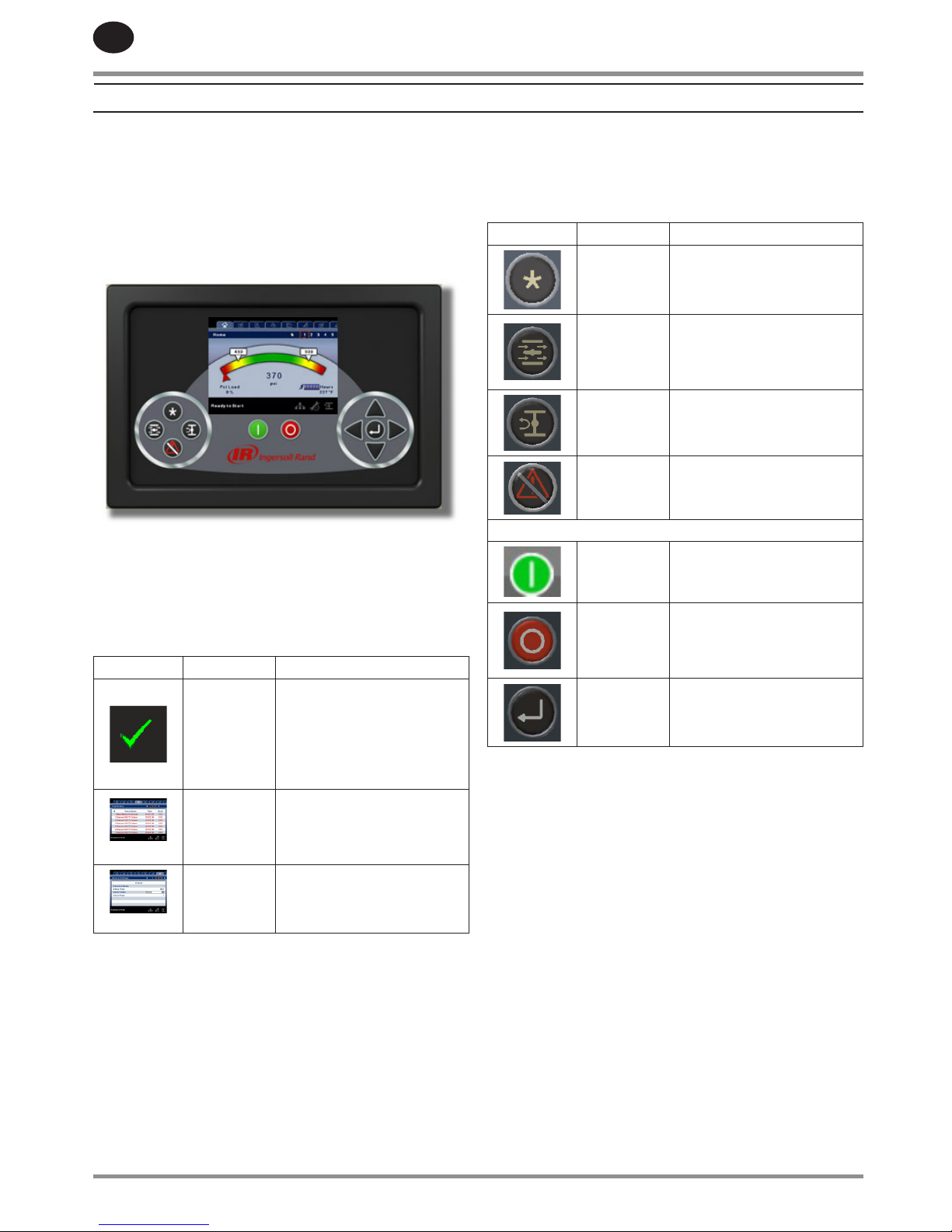
Xe-145M
The standard user interface conguration of the controller
consists of the membrane and the LCD display. The
membrane consists of ve command keys (Start, Stop, Load,
Unload, and Reset), four navigation keys (Up, Right, Left and
Down), and an Edit mode selection key (Enter). These keys,
in conjunction with the color graphics display and the LED
icons, make up the user interface to the compressor.
Figure : Xe-145M
LED STATUS ICONS
Three LED icons are used to indicate the current status of the
control system from a distance and are located on the upper
left side of the user interface.
Icon Name Function
OK
Illuminates when no
Warnings or Trips are sensed.
Can be in a Ready or Not
Ready state. This icon will
ash when the machine is
Running Unloaded
Alert
Illuminates when an Warning
(ashes) or Trip (constant on)
is sensed. Can be in a Ready
(Warning) or Tripped state.
Auto
Illuminates when the
compressor stops in auto
restart.
COMMAND KEYS
These keys command the controller to perform actions as
specied in the following table. When any of these keys are
pressed the action below will be initiated and logged in the
event log.
Key Name Function
--- None
Load
Puts the compressor into the
selected mode of operation.
Unit will load if the pressure
conditions are right.
Unload
Puts the compressor into an
unloaded state. Unit will run
unloaded indenitely.
Reset
Clears Warnings and Trips
once the condition is
corrected.
Start Starts the compressor.
Stop
Stops the compressor. This
button should be pressed
instead of the E-Stop for
normal stopping operation.
Enter
Toggles the display between
the Navigation mode and the
Edit mode.
Xe-145M Command Keys
80448905 Rev A 7
EN
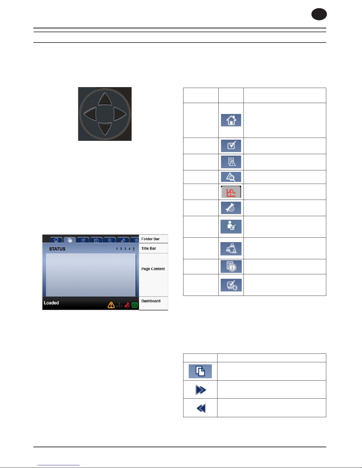
NAVIGATION KEYS
There are four navigation keys (UP, RIGHT, DOWN and LEFT).
While the ENTER key is not considered a navigation key, it
is used in conjunction with the navigation keys to make or
conrm a selection.
Xe-145M Navigation Keys
The navigation keys roll over. Pressing one of the navigation
keys will lead the user down a navigation path. Each time
the key is pressed, another step in the path is taken. Once
the end of a navigation path is reached, pressing the key one
more time will bring the user back to the beginning of the
path. Pressing the opposite key will move the user through
the navigation path in the opposite direction. Once the
beginning is reached, pressing the opposite key will take the
user to the end of the path.
DISPLAY LAYOUT
Xe-145M Display Layout
Folder Bar: Uses tabs to graphically identify each
folder.
Title Bar: Identies current folder and page
(underlined).
Page
Content:
Content of the current page.
Dashboard: Displays system status.
FOLDER NAVIGATION & ICONS
To move among the tabbed folders shown on the LCD display,
press the RIGHT and LEFT keys. The navigation rolls over from
the last to the rst folder and vice-versa.
Folder
Name
Icon Description
Home
System performance and status
main information. The rst page
of this folder is the default page
when the controller rst powers
up.
Operator
Settings
System options and conguration
settings.
Events System events log.
Trip History Details on the most recent trips.
Graphing
On-board graphing of system
data. (Xe-145M Only)
Maintenance
Status and notication setup for
compressor maintenance items.
General
Settings
General settings such as
Language, Time, and Units of
Measure.
Integral
Sequencing
Intergral Sequencing
communication status and
conguration.
Status
Measurements or status from/of
all analog and digital I/O.
Factory
Settings
Compressor tuning parameters.
Also displays hardware and
software versions.
Folder Bar Icons
PAGE NAVIGATION
Once the desired folder is selected, press the DOWN key to
move to the page selection area and then use the RIGHT and
LEFT keys to select the desired page. Use the UP key to get
back to the folder tabs.
Icon Description
Start of the page selection area.
Indicates that there are more pages available
by navigating right.
Indicates that there are more pages available
by navigating left.
Title Bar Page Icons
•
•
INTERFACE DATA & KEYS
EN
8 80448905 Rev A
ACCESSING PARAMETERS
After the desired page is selected, the page’s parameters can
be selected by using the DOWN key. The cursor will move to
the next parameter each time the DOWN key is pressed. Use
the UP key to go back to the previous one.
The cursor rolls over, so once the last parameter is selected,
pressing the DOWN key will navigate the cursor to the Folder
Bar. If the rst parameter is selected, pressing the UP key will
move the cursor to the page selection area.
Once selected, access parameters by pressing the ENTER key.
Make changes using the NAVIGATION keys and then enter the
setting by pressing the ENTER key again. Note that the LEFT
ARROW key is used to select a digit to adjust. The UP ARROW
and DOWN ARROW keys are used to set the digit higher and
lower. Pressing the RIGHT ARROW key will highlight the
cancel button.
When the cursor is on a parameter that has an enabled/
disabled box, pressing the ENTER key will cause the setting to
toggle.
The icon appears on numeric entry windows (see gure
below). Placing the cursor on it and then pressing the ENTER
key will cancel the entry and any changes that were made.
Not all pages have adjustable parameters. Some just
have read-only information.
DASHBOARD ICONS
The dashboard is intended to be a quick at-a-glance view of
system status. The following table lists standard dashboard
icons and their denition. Note that the color of these icons
changes based on the state set by the application while
running.
Name Icon Description
Remote
Control
Remote control is enabled. This
can be Remote Start/Stop, COM
Control, Integral Sequencing or
Web Control.
Service
Required
A service reminder is nearing or
has expired (i.e.: an air or oil lter
needs to be changed).
Unloaded
or
Loaded
Compressor is in the unloaded
state.
Compressor is in the loaded state.
Xe-145M Dashboard Icons
•
•
DASHBOARD STATUS MESSAGES
The dashboard also displays the current operating state of the
compressor. The following states can be encountered during
machine operation:
Ready to Start - – The compressor currently has no trip
or start inhibit conditions present. The machine can be
started by pressing the start button at any time
Starting – A start command has been given to the
compressor and the start sequence is being performed.
The time period for this state can vary depending on the
starter type of the machine.
Load Delay – The compressor is waiting for a small
period of time after starting before allowing the machine
to load. This ensures the machine is at operating
conditions before loading
Running Loaded – The compressor is operating and
producing air. The inlet valve is open and the blowo
valve is closed.
Running Unloaded – The compressor is operating,
but not producing air. The inlet valve is closed and the
blowo valve is open.
Auto-Restart – The compressor has stopped due to
pressure rising above the oine or auto-stop setpoints
and auto-restart being enabled. The compressor will
automatically restart when pressure falls to the online or
target pressure setpoint.
Stopping – The compressor has received a stop
command and the stop sequence is being performed.
Blowdown – The compressor must wait for a brief period
of time after stopping its motor before it is allowed to
start again.
Not Ready – The compressor has detected a condition
that will not allow the compressor to start. The condition
must be cleared before a start is allowed, but does not
need to be acknowledged.
Tripped – The compressor has detected an abnormal
operational condition that has stopped the machine. A
trip must be acknowledged by hitting the reset button
before the compressor can start.
Processor Init – The controller is being initialized.
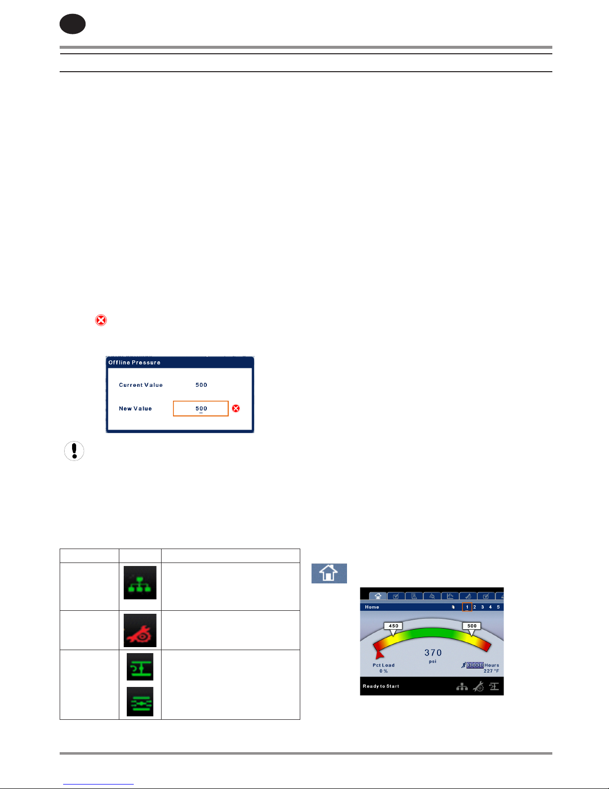
HOME FOLDER
SYSTEM OVERVIEW
This is the factory default display after powering up the
system.
•
•
•
•
•
•
•
•
•
•
•
•
•
INTERFACE DATA & KEYS
80448905 Rev A 9
EN
Load Pressure - indicated in the white box and by the
white arrow, which is always left of center on the gauge. The
compressor will load when package discharge pressure falls
below this value.
Unload Pressure - indicated in the white box and by the
white arrow, which is always right of center on the gauge. The
compressor will unload when package discharge pressure
rises above this value.
Package Discharge Pressure - indicated by the large
numbers centred below the gauge and by the red arrow. This
is the air pressure that the compressor is supplying to the
plant.
Pressure Unit of Measure - indicated below the Package
Discharge Pressure. This is selectable from the GENERAL
SETTINGS folder.
Package Discharge Temperature - indicated by the numbers
in the lower right of the display. This is the temperature of the
compressed air/at the discharge of the compression module.
The Package Discharge Temperature is only displayed if the
Hot Discharge option is disabled.
Temperature Unit of Measure - indicated to the right of the
Airend Discharge Temperature. This is selectable from the
GENERAL SETTINGS folder.
Percent Load - Indicates the current capacity being delivered
by the compressor. Note that this will vary based on the load
control method of the compressor. Two step control will
show only 0% or 100%. Three step control will show 0%, 50%,
and 100%. Five step control will show 0%, 25%, 50%, 75%,
and 100%
Run Hours indicate the number of hours the compressor has
been running.
All information on this page is read only.
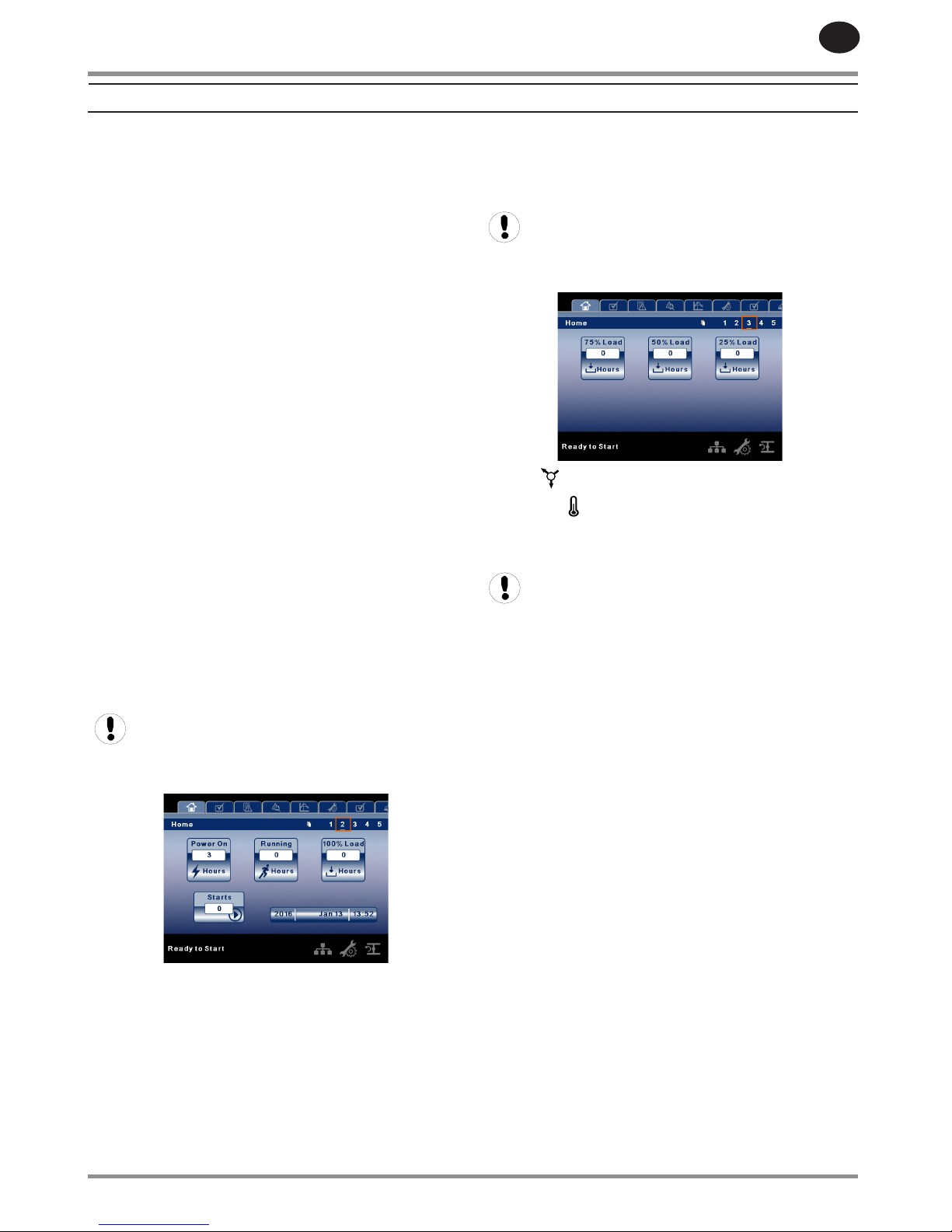
COUNTERS
Hour Meters - Indicates the hours that: the controller has
been powered up, the compressor has been running, and
the compressor has running loaded. at 100%, loaded at 75%,
loaded at 50%, or loaded at 25% capacity. Note that the
number of counters will vary depending on the compressor
type. Compressors with two step control will only display
100% Loaded Hours. Compressors with three step control will
display 100% and 50% Loaded Hours. Compressors with ve
step control will display 100%, 75%, 50%, and 25% Loaded
Hours.
•
Starts - Indicates the number of times a start is attempted on
the compressor.
Date & Time – Indicates the current date and time. This is
adjustable and congurable in the GENERAL SETTINGS folder.
All information on this page is read only.
ANALOG INPUTS
Pressure is indicated by this icon.
Temperature is indicated by this icon.
Any sensor that is not installed or is reporting a failure will
show an X symbol.
All information on these pages is read only.
The following analog inputs are displayed in this section.
Frame Oil Pressure – The pressure of the oil being delivered
to the cylinder.
Water Inlet Pressure - The pressure of the cooling water at
the intake to the cooling system
Water Outlet Pressure - The pressure of the cooling water at
the discharge of the cooling system
Package Discharge Pressure - The pressure the compressor
is delivering to the plant
1st Stage Discharge Pressure - The pressure of the air at the
discharge of the rst stage of the compression module
2nd Stage Discharge Pressure - The pressure of the air at the
discharge of the second stage of the compression module
Suction Pressure - The pressure if the intake air to the
compressor when boosted from another compressor.
Inlet vacuum - The vacuum reading at the inlet valve
Frame Oil Temperature - The temperature of oil being
delivered to the cylinder
Water Inlet Temperature - The temperature of the cooling
water at the intake of the machine
2nd Stage Inlet Temperature - The temperature of the air at
the intake of the second stage of the airend.
3rd Stage Inlet Temperature - The temperature of the air at
the intake of the third stage of the airend.
•
RECIPROCATING COMPRESSORS
EN
10 80448905 Rev A
Package Discharge Temperature - The temperature of the
air as delivered to the plant.
1st Stage Discharge Temperature - The temperature of the
air as it leaves the rst stage of the compression module.
2nd Stage Discharge Temperature- The temperature of the
air as it leaves the second stage of the compression module.
3rd Stage Discharge Temperature - The temperature of the
air as it leaves the third stage of the compression module.
1st Cylinder Discharge Temperature - The temperature
of the air as it leaves the rst compression module of a two
airend compressor
2nd Cylinder Discharge Temperature - The temperature of
the air as it leaves the second compression module of a two
airend compressor
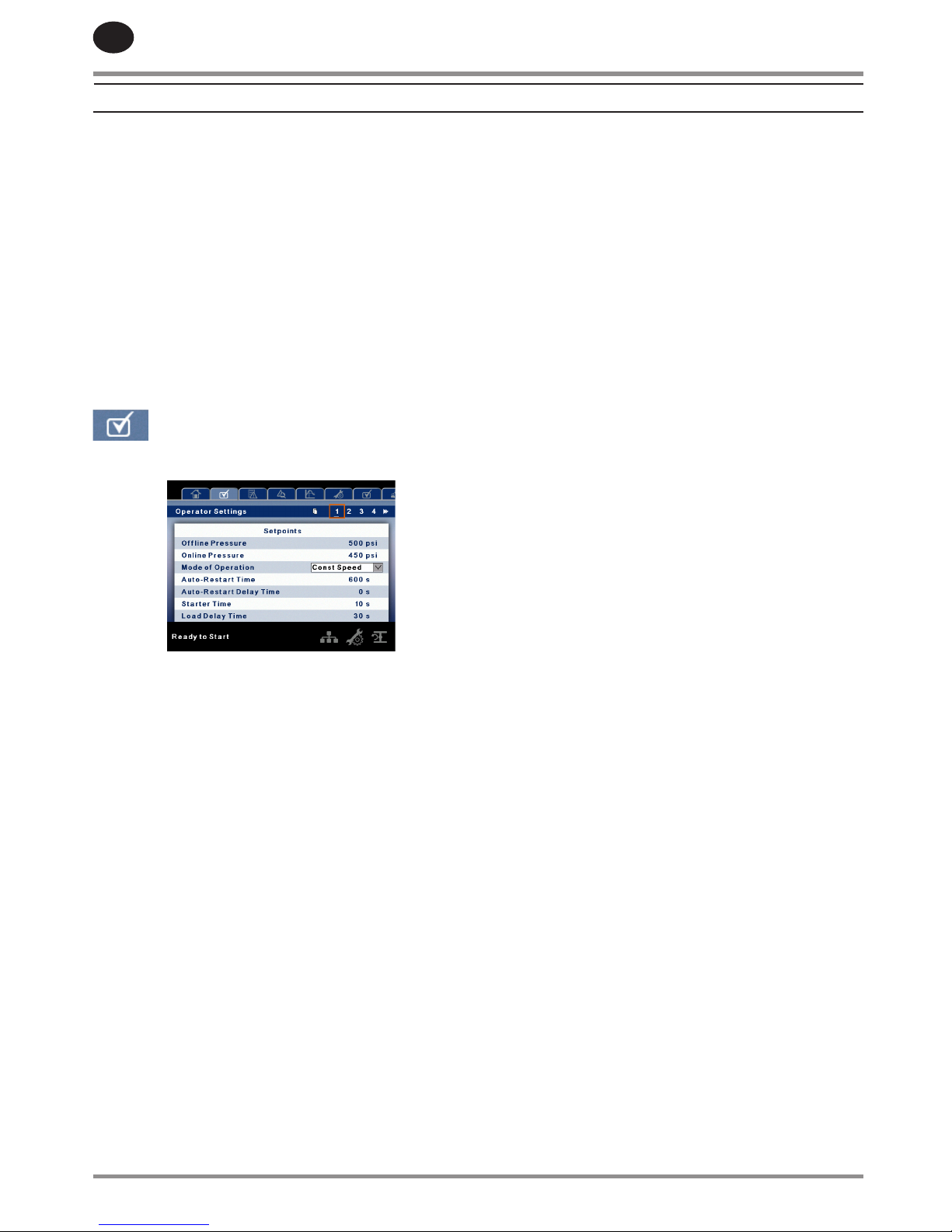
OPERATOR SETTINGS FOLDER
OPERATOR SETTINGS
The below values are all setpoints.
Oine Pressure – The compressor will unload when package
discharge pressure rises above this value. Range (in PSI): 30 to
Rated Pressure
Online Pressure – The compressor will load when the
package discharge pressure falls below this value Range (in
PSI): 20 to Oine Pressure - 2
Starter Time – Time period that the compressor needs in
order to come up to operating speed after a start command
before being able to produce air.
Range (in seconds): 5 - 30.
Load Delay Time - Determines how long after the
compressor starts the machine must wait prior to
compressing air.
Range (in seconds): 15 - 60
High 1st Stage Discharge Temperature Trip - Determines
the trip point for the 1st Stage Discharge Temperature
reading.
Range (in degF): 150 - 500
Compressors Present: ESV Atmospheric, Two Stage
Atmospheric, Three Stage Atmospheric, ESV Booster
High 2nd Stage Discharge Temperature Trip - Determines
the trip point for the 2nd Stage Discharge Temperature
reading.
•
Range (in degF): 150 - 500
Compressors Present: Two Stage Atmospheric, Three Stage
Atmospheric
High 3rd Stage Discharge Temperature Trip - Determines
the trip point for the 3rd Stage Discharge Temperature
reading.
Range (in degF): 150 - 500
Compressors Present: Three Stage Atmospheric
High 1st Cylinder Discharge Temperature Trip - Determines
the trip point for the 1st Cylinder Discharge Temperature
reading
Range (in degF): 150 - 500
Compressors Present: Two Airend Booster
High 2nd Cylinder Discharge Temperature Trip -
Determines the trip point for the 1st Cylinder Discharge
Temperature reading
Range (in degF): 150 - 500
Compressors Present: Two Airend Booster
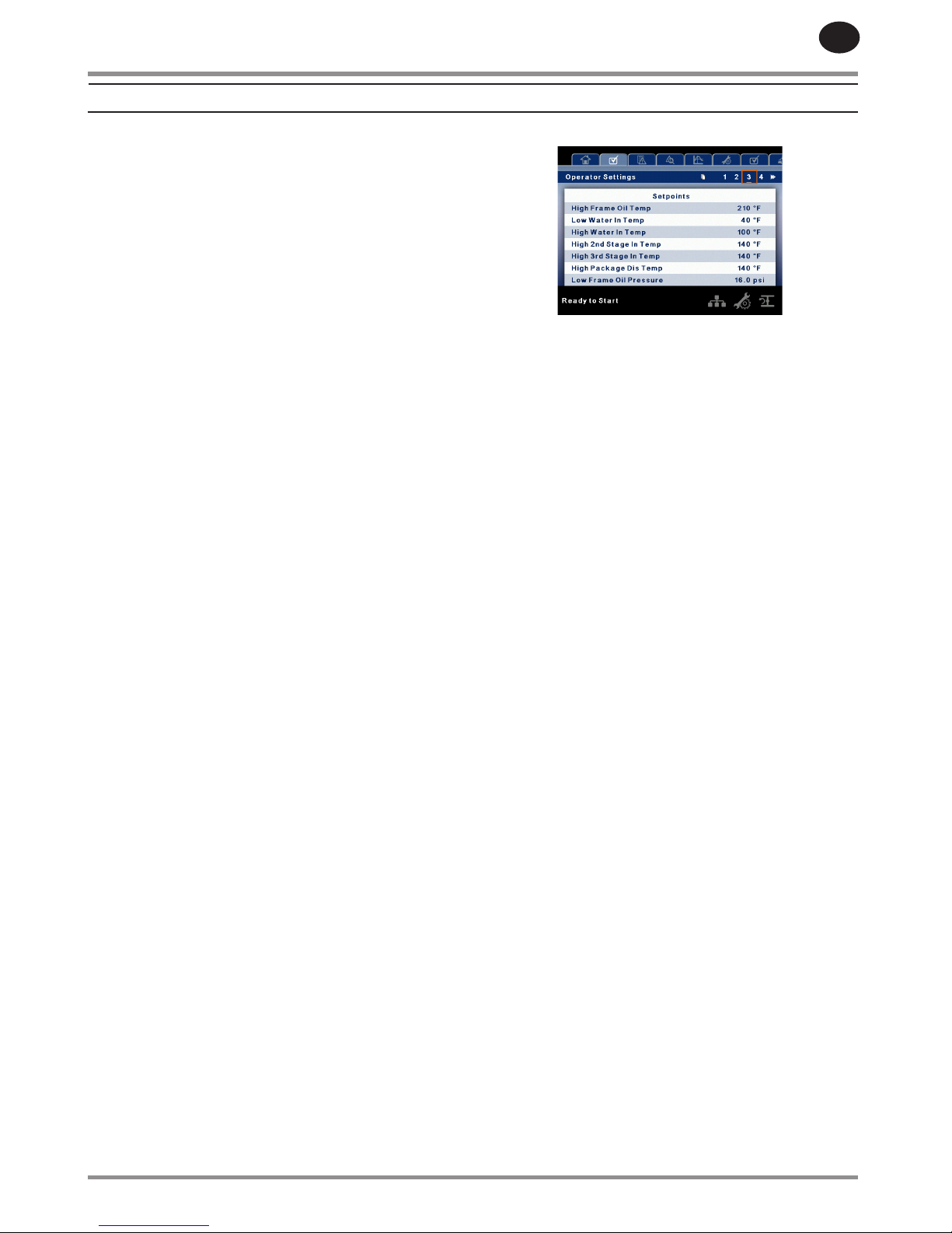
High Frame Oil Temperature Trip - Determines the trip point
for the Frame Oil Temperature reading
Range (in degF): 120 - 210
Compressors Present: ALL
Low Water Inlet Temperature Trip - Determines the trip
point for the Water Inlet Temperature reading
Range (in degF): 20 - 50
Compressors Present: ALL
High Water Inlet Temperature Trip - Determines the trip
point for the Water Inlet Temperature reading
Range (in degF): 50 - 150
Compressors Present: ALL
High 2nd Stage Inlet Temperature Trip- Determines the trip
point for the 2nd Stage Inlet Temperature reading
Range (in degF): 80 - 160
Compressors Present: Two Stage Atmospheric, Three Stage
Atmospheric, Two Stage Booster
High 3rd Stage Inlet Temperature Trip - Determines the trip
point for the 3rd Stage Inlet Temperature reading
Range (in degF): 80 - 160
Compressors Present: Three Stage Atmospheric
High Package Discharge Temperature Trip - Determines the
trip point for the Package Discharge Temperature reading
Range (in degF): 80 - 500
Compressors Present: ALL
High 1st Stage Discharge Pressure Trip - Determines the
trip point for the 1st Stage Discharge Pressure reading
Range (in psi): 25 - 100
RECIPROCATING COMPRESSORS
80448905 Rev A 11
EN
Compressors Present: Two Stage Atmospheric, Three Stage
Atmospheric, Two Stage Booster
High 2nd Stage Discharge Pressure Trip - Determines the
trip point for the 2nd Stage Discharge Pressure reading
Range (in psi): 100 - 400
Compressors Present: Three Stage Atmospheric
Low Frame Oil Presure Trip - Determines the trip point for
the Frame Oil Pressure reading
Range (in psi): 8 - 60
Compressors Present: ALL
Low Water Inlet Pressure Trip - Determines the trip point for
the Water Inlet Pressure reading
Range (in psi): 10 - 40
Compressors Present: ALL
High Water Inlet Pressure Trip - Determines the trip point
for the Water Inlet Pressure reading
Range (in psi): 50 - 76
Compressors Present: ALL
Package Water Pressure Loss Trip - Determines the trip
point for the the water pressure drop reading
Range (in psi): 0 - 40
Compressors Present: ALL
Condensate Release Time - Time period that determines
how long the condensate drain valve will remain open every
cycle.
Range 3 - 60 seconds
Condensate Interval Time - Time period that determines
how long the condensate drain will remain closed every cycle
Range 60 - 300 seconds
Mode of Operation - Selects whether the compressor is
allowed to shut o the motor after a minimum running time
(Auto-Dual) or will remain running in an unloaded state until
air is required.
The parameters on these pages are adjustable any time
Auto-Restart Time – The time period the compressor must
run unloaded before stopping in auto-restart. This time
period begins the moment that package discharge pressure
rises above the oine setpoint. Both this time period and
the minimum motor run timer (10 minutes) must be satised
before the compressor will stop in auto restart.
Range (in seconds) 120 - 900
OPERATOR OPTIONS
The below values are all setpoints
Auto-Restart Delay – The time period after the package
discharge pressure has fallen below the online setpoint
before the compressor can automatically restart
Range (in seconds): 0 - 60
Remote Start/Stop – Enabling this setpoint allows the
compressor to be started and stopped using the digital inputs
on the controller.
COM Control – Enabling this setpoint allows the compressor
to be controlled by a serial or Ethernet device, such as an X8I.
This is equivalent to the “Sequencer” option on older Intellisys
controllers.
Closed Loop Water System - Enabling this setpoint will
ensure that the compressor allows water to ow through the
cooling system for two minutes prior to starting the machine
Enable PORO – Enabling this setpoint will allow the
compressor to automatically restart after a power outage has
been restored if the compressor was running loaded at the
time of the outage. PORO is an option and the option module
must be purchased and installed before this feature can be
turned on.
PORO Time – Time after the controller power has been
restored and controller has nished booting before the
compressor will perform a PORO start. During this time the
PORO Horn will sound.
Range (in seconds): 10 - 600
Enable Inlet Filter Monitoring - Enabling this setting
will turn on the optional inlet lter monitoring function.
This function will alert the user if the air lter is in need of
replacement. Note that this requires an optional inlet vacuum
sensor to be installed in the compressor
Compressors Present: ESV Atmospheric, Two Stage
Atmospheric, Three Stage Atmospheric
Air Filter Pressure Drop Value - Determines at what inlet
vacuum reading the controller will issue a change inlet lter
warning
Range (in psi): 0.2 - 1.0
Compressors Present: ESV Atmospheric, Two Stage
Atmospheric, Three Stage Atmospheric
•
RECIPROCATING COMPRESSORS
EN
12 80448905 Rev A
CALIBRATE SENSORS
Sensor calibration can only take place when the machine is
stopped and there is no pressure on the sensor. Calibration
only needs to take place after a sensor is replaced, the
controller is replaced, the controller software is upgraded, or
the operator suspects the sensor reading is in error. Calibrate
a sensor by selecting the checkbox beside the sensor name.
Each of the sensors listed below can be calibrated.
Frame Oil Pressure
Water Inlet Pressure
Water Outlet Pressure
Package Discharge Pressure
1st Stage Discharge Pressure
2nd Stage Discharge Pressure
Inlet Vacuum Optional - Atmospheric Machines Only)
Suction Pressure - Booster Machines Only
Please note that if a sensor is currently reading a value that is
+/- 10% of its range from zero, the sensor will not be able to
be calibrated and an warning will be logged in the event log.
Please make sure the sensor is being exposed to atmosphere
before attempting calibration.
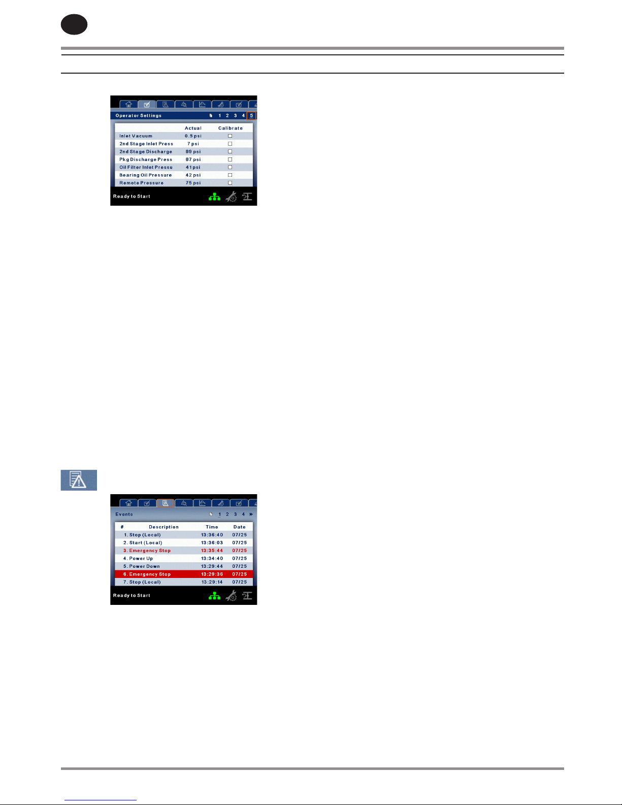
EVENTS FOLDER
The pages in the Events folder document up to the last 250
events that the controller has experienced, with the time and
date of the occurrence. The events are recorded in sequence,
with number one being the newest and 250 being the oldest.
When a new event occurs, it becomes number one and all
others are shifted up in number.
The page numbers in the Title Bar are used to scroll through
the events, with each page displaying up to seven.
The following items will generate an event
•
•
•
•
•
•
•
•
•
Power On
Power O
Press the Start Key
Press the Stop Key
Press the Load Key
Press the Unload Key
Starting the compressor remotely
Stopping the compressor remotely
Warning
Trip
Start Inhibit
Active Warnings will be highlighted in amber while
acknowledged Warnings will have amber text.
Active Trips will be highlighted in red while acknowledged
Trips will have red text.
Active Start Inhibits will be listed in the Event log. The
display will highlight the start inhibit in blue and indicate the
compressor is not ready to start if a start inhibit is active.
Warning Events List
Motor Not Synchronized
On Screen Text: Motor Not Synchronized
Compressors Present: ALL
Will occur if the compressor is congured with a synchronized
motor starter, has been running for a time period equal or
greater than the load delay time setting, and the 2SL contact
input opens. This warning has a 3 second delay before being
recorded. Note that once this warning occurs, the compressor
will go into an unloaded mode. The compressor will not be
allowed to load again until the 2SL contact input closes, the
user resets the warning, and the load button is pressed to reenable compressor loading.
Change Inlet Filter
On-Screen Text: Change Inlet Filter
Compressors Present: ESV Atmospheric, Two Stage
Atmospheric, Three Stage Atmospheric.
Will occur if the Enable Inlet Filter Monitoring function is
enabled, the compressor has been in a loaded state for at
least 10 seconds and the inlet vacuum (3AVPT) reading is
greater than the air lter pressure drop value for at least 3
seconds.
Low Suction Pressure
On Screen Text: Low Suction Pressure
Compressors Present: ESV Booster, Two Stage Booster,
Two Airend Booster
Will occur if the compressor has been running for a time
period equal of greater than the load delay time setting and
the suction pressure is less than or equal to the low suction
pressure set point plus 5%. This warning has a 3 second delay
•
•
•
•
•
•
•
•
•
•
•
•
RECIPROCATING COMPRESSORS

80448905 Rev A 13
EN
before being recorded
High Suction Pressure
On Screen Text: High Suction Pressure
Compressors Present: ESV Booster, Two Stage Booster, Two
Airend Booster
Will occur if the compressor has been running for a time
period equal of greater than the load delay time setting and
the suction pressure is greater than or equal to the high
suction pressure set point minus 5%. This warning has a 3
second delay before being recorded
High 1st Stage Discharge Pressure
On Screen Text: High 1st Stage Discharge
Compressors Present: Two Stage Atmospheric, Three Stage
Atmospheric, Two Airend Booster
Will occur if the compressor has been running for at least
Start Time + 10 seconds (Star/Delta) or for 15 seconds (Other
starter types), is in a loaded state, and the 1st Stage Discharge
Pressure reading is greater than or equal to the 1st Stage
Discharge Pressure trip set point minus 5%. This warning has
a 3 second delay before being recorded
High 2nd Stage Discharge Pressure
On Screen Text: High 2nd Stage Discharge
Compressors Present: Three Stage Atmospheric
Will occur if the compressor has been running for at least
Start Time + 10 seconds (Star/Delta) or for 15 seconds
(Other starter types), is in a loaded state, and the 2nd Stage
Discharge Pressure reading is greater than or equal to the
2nd Stage Discharge Pressure trip set point minus 5%. This
warning has a 3 second delay before being recorded
High Package Discharge Pressure
On Screen Text: High Package Discharge
Compressors Present: ALL
Will occur if the compressor has been running for at least
Start Time + 10 seconds (Star/Delta) or for 15 seconds (Other
starter types) and the Package Discharge Pressure reading
is greater than rated pressure + 3%. This warning has a 3
second delay before being recorded
Over Pressure
On-Screen Text: Over Pressure
Compressor Present: ALL
Will occur if the unit is using a remote sensor or is under the
control of an external device, such as an X8I, is loaded, and
the discharge pressure (2APT) is greater than the maximum
oine pressure. This condition must exist for 3 seconds before
the warning is issued. If this condition occurs, the compressor
will automatically unload. The unit will be available to reload
once the discharge pressure falls to the maximum online
pressure.
•
High Frame Oil Temperature
On Screen Text: High Frame Oil Temperature
Compressors Present: ALL
Will occur if the compressor has been running for at least
Start Time + 10 seconds (Star/Delta) or for 15 seconds (Other
starter types) and the Frame Oil temperature reading is
greater than or equal to the High Frame Oil Temperature
Trip set point - 5%. This warning has a 3 second delay before
being recorded
Low Package Water Inlet Temperature
On Screen Text: TBD
Compressors Present: ALL
Will occur if the compressor has been running for at least
Start Time + 10 seconds (Star/Delta) or for 15 seconds (Other
starter types) and the Water Inlet Temperature reading is
less than or equal to the Low Water Inlet Temperature Trip
set point plus 7%. This warning has a 3 second delay before
being recorded
High Package Water Inlet Temperature
On Screen Text: TBD
Compressors Present: ALL
Will occur if the compressor has been running for at least
Start Time + 10 seconds (Star/Delta) or for 15 seconds (Other
starter types) and the Water Inlet Temperature reading is
greater than or equal to the High Water Inlet Temperature Trip
set point minus 7%. This warning has a 3 second delay before
being recorded
High 2nd Stage Inlet Temperature
On Screen Text: TBD
Compressors Present: Two Stage Atmospheric, Three Stage
Atmospheric, Two Stage Booster
Will occur if the compressor has been running for at least
Start Time + 10 seconds (Star/Delta) or for 15 seconds (Other
starter types) and the 2nd Stage Inlet Temperature reading is
greater than or equal to the High 2nd Stage Inlet Temperature
set point minus 7%. This warning has a 3 second delay before
being recorded
High 3rd Stage Inlet Temperature
On Screen Text: TBD
Compressors Present: Three Stage Atmospheric
Will occur if the compressor has been running for at least
Start Time + 10 seconds (Star/Delta) or for 15 seconds (Other
starter types) and the 3rd Stage Inlet Temperature reading is
greater than or equal to the High 3rd Stage Inlet Temperature
Trip set point minus 7%. This warning has a 3 second delay
before being recorded
RECIPROCATING COMPRESSORS

EN
14 80448905 Rev A
High 1st Cylinder Discharge Temperature
On Screen Text: TBD
Compressors Present: Two Airend Booster
Will occur if the compressor has been running for at least Start
Time + 10 seconds (Star/Delta) for 15 seconds (Other starter
types) and the 1st Cylinder Discharge Temperature reading
is greater than or equal to the High 1st Cylinder Discharge
Temperature Trip set point minus 3%. This warning has a 3
second delay before being recorded
High 2nd Cylinder Discharge Temperature
On Screen Text: TBD
Compressors Present: Two Airend Booster
Will occur if the compressor has been running for at least
Start Time + 10 seconds (Star/Delta) or for 15 seconds (Other
starter types) and the 2nd Cylinder Discharge Temperature
reading is greater than or equal to the High 2nd Cylinder
Discharge Temperature Trip set point minus 3%. This warning
has a 3 second delay before being recorded
High 1st Stage Discharge Temperature
On Screen Text: TBD
Compressors Present: ESV Atmospheric, Two Stage
Atmospheric, Three Stage Atmospheric, ESV Booster, Two
Stage Booster
Will occur if the compressor has been running for at least
Start Time + 10 seconds (Star/Delta) or for 15 seconds (Other
starter types) and the 1st Stage Discharge Temperature
reading is greater than the High 1st Stage Discharge
Temperature Trip set point minus 3%. This warning has a 3
second delay before being recorded
High 2nd Stage Discharge Temperature
On Screen Text: TBD
Compressors Present: Two Stage Atmospheric, Three Stage
Atmospheric, Two Stage Booster
Will occur if the compressor has been running for at least Start
Time + 10 seconds (Star/Delta) orfor 15 seconds (Other starter
types) and the 2nd Stage Discharge Temperature reading is
greater than the High 2nd Stage Discharge Temperature Trip
set point minus 3%. This warning has a 3 second delay before
being recorded
High 3rd Stage Discharge temperature
On Screen Text: TBD
Compressors Present: Three Stage Atmospheric
Will occur if the compressor has been running for at least
Start Time + 10 seconds (Star/Delta) or for 15 seconds (Other
starter types) and the 3rd Stage Discharge Temperature
reading is greater than the High 3rd Stage Discharge
Temperature Trip set point minus 3%. This warning has a 3
second delay before being recorded
High Package Discharge Temperature
On Screen Text: TBD
Compressors Present: ALL
Will occur if the compressor has been running for at least
Start Time + 10 seconds (Star/Delta) or for 15 seconds (Other
starter types) and the Package Discharge Temperature
reading is greater than or equal to the High Package
Discharge Temperature Trip set point minus 7%. This warning
has a 3 second delay before being recorded
Low Frame Oil Pressure
On Screen Text: TBD
Compressors Present: ALL
Will occur if the compressor has been running for at least
Start Time + 10 seconds (Star/Delta) or for 15 seconds (Other
starter types) and the Frame Oil Pressure reading is less
than or equal to the Low Frame Oil Pressure Trip set point
plus 20%. This warning has a 3 second delay before being
recorded
Low Water Inlet Pressure
On Screen Text: TBD
Compressors Present: ALL
Will occur if the compressor has been running for at least
Start Time + 10 seconds (Star/Delta) or for 15 seconds (Other
starter types) and the Water Inlet Pressure reading is less than
or equal to the Low Water Inlet Pressure Trip set point plus
20%. This warning will be ignored if the Closed Loop Water
System function is enabled. This warning has a 3 second
delay before being recorded
High Water Inlet Pressure
On Screen Text: TBD
Compressors Present: ALL
Will occur if the compressor has been running for at least
Start Time + 10 seconds (Star/Delta) or for 15 seconds (Other
starter types) and the Water Inlet Pressure reading is greater
than or equal to the High Water Inlet Pressure Trip set point
minus 5%. This warning has a 3 second delay before being
recorded
Low Water Pressure Drop
On Screen Text: TBD
Compressors Present: ALL
Will occur if the compressor has been running for at least
Start Time + 10 seconds (Star/Delta) or for 15 seconds (Other
starter types), The Water Inlet Pressure reading is greater than
the Water Outlet Pressure reading, and the pressure drop
between the inlet and outlet is less than or equal to the Low
Water Pressure Drop Trip set point plus 20%. This warning has
a 3 second delay before being recorded
RECIPROCATING COMPRESSORS

80448905 Rev A 15
EN
Sensor Failure
On-Screen Text: 3AVPT Failure
Compressors Present: ESV Atmospheric, Two Stage
Atmospheric, Three Stage Atmospheric. This will occur
whenever sensors 3AVPT are recognized as missing or broken.
The sensor failure message shall follow the following format:
3AVPT FAILURE. This condition must exist for 3 seconds before
the warning is issued.
Invalid Calibration
On-Screen Text: Invalid Cal
Compressor Present: ALL
Will occur if the sensor zero value is +/- 10% of its scale. See
Sensor Calibration.
Emergency Stop
On-Screen Text: Emergency Stop
Emergency Stop is rst in the trip list
This will occur when the EMERGENCY STOP button is
engaged.
Main Motor Overload
On-Screen Text: Main Motor OL
Compressors Present: ALL
This will occur if the motor overload relay opens. The contact
must be open for at least 3 seconds before the trip will occur.
Starter Fault 1SL (2SL)
Compressors Present: ALL
On-Screen Text: Starter Fault 1SL, Starter Fault 2SL
Will occur if the unit tries to start and either of the starter
auxiliary contacts are already closed.
Will also occur if the unit is in a running condition and the
starter auxiliary contacts open.
Remote Start Failure
On-Screen Text: Rem Start Fail
Compressors Present: ALL
Will occur if the remote start/stop option is enabled, the unit
is started by the remote start button, and the button stays
closed for 7 seconds after the unit starts.
Remote Stop Failure
On-Screen Text: Rem Stop Fail
Compressors Present: ALL
Will occur if the remote start/stop option is enabled, the
remote stop button remains open and either start button is
pressed.
High Vibration:
On Screen Text: High Vibration
Compressors Present: ALL
•
•
•
•
•
•
•
Will occur if the compressor is running and the high vibration
switch opens for at least three seconds
High Package Discharge Pressure
On-Screen Text: High Pkg Discharge Press
Compressors Present: ALL
Will occur if the compressor is running or stopped and the
package discharge pressure is greater than the rated pressure
plus 8%.
High 1st Stage Discharge Pressure
On-Screen Text: High 1st Stage Disch P
Compressors Present: Two Stage Atmospheric, Three Stage
Atmospheric, Two Stage Booster
Will occur if the compressor has been running for at least
Start Time + 10 seconds (Star/Delta) or for 15 seconds (Other
starter types), is in a loaded state, and the 1st Stage Discharge
Pressure reading is greater than or equal to the 1st Stage
Discharge Pressure trip set point.
High 2nd Stage Discharge Pressure
On-Screen Text: High 2nd Stage Disch P
Compressors Present: Three Stage Atmospheric,
Will occur if the compressor has been running for at least
Start Time + 10 seconds (Star/Delta) or for 15 seconds
(Other starter types), is in a loaded state, and the wnd Stage
Discharge Pressure reading is greater than or equal to the 2nd
Stage Discharge Pressure trip set point.
Low Suction Pressure
On-Screen Text: Low Suction
Compressors Present: ESV Booster, Two Stage Booster, Two
Airend Booster
Will occur if the compressor has been running for at least
Start Time + 10 seconds (Star/Delta) or for 15 seconds (Other
starter types) and the suction pressure is less than or equal to
the low suction pressure setpoint
High Suction Pressure
On-Screen Text: High Suction
Compressors Present: ESV Booster, Two Stage Booster, Two
Airend Booster
Will occur if the compressor has been running for at least
Start Time + 10 seconds (Star/Delta) or for 15 seconds (Other
starter types) and the suction pressure is greater than or
equal to the high suction pressure setpoint
Trip Events List
High Package Inlet Temperature
On Screen Text: High Package Inlet
Compressors Present: ESV Booster, Two Stage Booster, Two
Airend Booster
Will occur if the compressor has been running for at least
Start Time + 10 seconds (Star/Delta) or for 15 seconds (Other
RECIPROCATING COMPRESSORS

EN
16 80448905 Rev A
starter types) and the high package inlet temperature switch
opens for at least three seconds
High 1st Stage Discharge Temperature
On Screen text: High 1st Stg DischT
Compressors present: ALL
Will occur if the compressor has been running for at least
Start Time + 10 seconds (Star/Delta) or for 15 seconds (Other
starter types) and the 1st stage discharge temperature
is greater than or equal to the high 1st stage discharge
temperature setpoint
High 1st Cylinder Discharge Temperature
On Screen text: High 1st Cyl DischT
Compressors present: Two Airend Booster
Will occur if the compressor has been running for at least
Start Time + 10 seconds (Star/Delta) or for 15 seconds (Other
starter types) and the 1st cylinder discharge temperature
is greater than or equal to the high 1st cylinder discharge
temperature setpoint
High 2nd Cylinder Discharge Temperature
On Screen text: High 2nd Cyl DischT
Compressors present: Two Airend Booster
Will occur if the compressor has been running for at least
Start Time + 10 seconds (Star/Delta) or for 15 seconds (Other
starter types) and the 2nd cylinder discharge temperature
is greater than or equal to the high 2nd cylinder discharge
temperature setpoint
High 2nd Stage Inlet Temperature
On Screen text: High 2nd Stg InletT
Compressors present: Two Stage Atmospheric, Three Stage
Atmospheric, Two Stage Booster
Will occur if the compressor has been running for at least
Start Time + 10 seconds (Star/Delta) or for 15 seconds (Other
starter types) and the 2nd Stage Inlet temperature is greater
than or equal to the high 2nd stage inlet temperature
setpoint
High 2nd Stage Discharge Temperature
On Screen text: High 2nd Stg DischT
Compressors present: Two Stage Atmospheric, Three Stage
Atmospheric, Two Stage Booster
Will occur if the compressor has been running for at least
Start Time + 10 seconds (Star/Delta) or for 15 seconds (Other
starter types) and the 2nd stage discharge temperature
is greater than or equal to the high 2nd stage discharge
temperature setpoint
High 3rd Stage Inlet Temperature
On Screen text: High 3rd Stg InletT
Compressors present: Three Stage Atmospheric
Will occur if the compressor has been running for at least
Start Time + 10 seconds (Star/Delta) or for 15 seconds (Other
starter types) and the 3rd Stage Inlet temperature is greater
than or equal to the high 3rd stage inlet temperature setpoint
High 3rd Stage Discharge Temperature
On Screen text: High 3rd Stg DischT
Compressors present: Three Stage Atmospheric
Will occur if the compressor has been running for at least
Start Time + 10 seconds (Star/Delta) or for 15 seconds (Other
starter types) and the 3rd stage discharge temperature
is greater than or equal to the high 3rd stage discharge
temperature setpoint
High Package Discharge Temperature
On Screen text: High Pkg DischT
Compressors present: ALL
Will occur if the compressor has been running for at least
Start Time + 10 seconds (Star/Delta) or for 15 seconds (Other
starter types) and the package discharge temperature
is greater than or equal to the high package discharge
temperature setpoint
Lubricator Line Alert
On Screen text: Lubricator Line Alert
Compressors Present: ALL
Will occur if the compressors has been running for at least 90
seconds and the lubricator line alert switch opens for at least
three seconds.
Low Lubricator Oil Level
On Screen text: Low Lubricator Oil Level
Compressors Present: ALL
Will occur if the compressor has been running for at least 90
seconds and the low lubricator oil level switch closes for at
least three seconds
Low Frame Oil Level
On Screen text: Low Frame Oil Level
Compressors Present: ALL
Will occur if the compressor is running and the frame oil level
switch closes for at least three seconds.
Low Frame Oil Pressure
On Screen text: Low Frame Oil Pressure
Compressors Present: ALL
Will occur if the compressor has been running for at least
Start Time + 10 seconds (Star/Delta) or for 15 seconds (Other
starter types) and the frame oil pressure is less than or equal
to the low frame oil pressure setpoint.
Low Water Inlet Pressure
On Screen text: Low Water Inlet Pressure
Compressors Present: ALL
Will occur if the compressor has been running for at least
Start Time + 10 seconds (Star/Delta) or for 15 seconds (Other
RECIPROCATING COMPRESSORS

80448905 Rev A 17
EN
starter types) and the water inlet pressure is less than or equal
to the low water inlet pressure setpoint. Note that this trip is
ignored if a closed loop water system is selected.
High Water Inlet Pressure
On Screen text: High Water Inlet Pressure
Compressors Present: ALL
Will occur if the compressor has been running for at least
Start Time + 10 seconds (Star/Delta) or for 15 seconds (Other
starter types) and the water inlet pressure is greater than or
equal to the high water inlet pressure setpoint.
Low Water Pressure Drop
On Screen text: Low Water Pressure Drop
Compressors Present: ALL
Will occur if the compressor has been running for at least
Start Time + 10 seconds (Star/Delta) or for 15 seconds (Other
starter types), the water inlet pressure is greater than the
water outlet pressure, and the package water pressure loss
(Water Inlet Pressure - Water Outlet Pressure) is greater than
or equal to the package water pressure loss setpoint
Low Package Water Inlet Temperature
On Screen text: Low Water Inlet Temperature
Compressors Present: ALL
Will occur if the compressor has been running for at least
Start Time + 10 seconds (Star/Delta) or for 15 seconds (Other
starter types) and the package water inlet temperature is less
than or equal to the low package water inlet temperature
setpoint.
High Package Water Inlet Temperature
On Screen text: High Water Inlet Temperature
Compressors Present: ALL
Will occur if the compressor has been running for at least
Start Time + 10 seconds (Star/Delta) or for 15 seconds (Other
starter types) and the package water inlet temperature
is greater than or equal to the high package water inlet
temperature setpoint.
High Package Water Outlet Temperature
On Screen text: High Water Outlet Temperature
Compressors Present: ALL
Will occur if the compressor has been running for at least
Start Time + 10 seconds (Star/Delta) or for 15 seconds (Other
starter types) and the package water outlet temperature
is greater than or equal to the high package water outlet
temperature setpoint.
High Intercooler Condensate Level
On Screen text: High Intercooler Condensate
Compressors Present: ALL
Will occur if the compressor is running and the intercooler
condensate level switch opens for at least three seconds.
High Aftercooler Condensate Level
On Screen text: High Aftercooler Condensate
Compressors Present: ALL
Will occur if the compressor is running and the aftercooler
condensate level switch opens for at least three seconds.
High 1st Stage Temperature
On Screen Text: High 1st Stage Temp
Will occur if the compressor is running and the 1st stage
discharge temperature sensor reads a value greater than the
High 1st Stage Temperature setpoint
High 2nd Stage Temperature
On Screen Text: High 2nd Stage Temp
Will occur if the compressor is running and the 2nd stage
discharge temperature sensor reads a value greater than the
High 2nd Stage Temperature setpoint
Sensor Failure
On-Screen Text: Sensor 1APT Failure, Sensor 2APT Failure,
Sensor 4OPT Failure, Sensor 5WPT Failure, Sensor 6WPT
Failure, SEnsor 7APT Failure, Sensor 1ATT Failure, Sensor 2ATT
Failure, Sensor 3OTT Failure, Sensor 4ATT Failure, Sensor 5ATT
Failure, Sensor 6ATT Failure, Sensor 7WTT Failure, Sensor 8ATT
Failure.
This will occur when a sensor is recognized as missing or
broken. The sensors aected by this trip are 1APT, 2APT, 4OPT,
5WPT, 6WPT, 7APT, 1ATT, 2ATT, 3OTT, 4ATT, 5ATT, 6ATT, 7WTT,
8ATT. The sensor should be displayed along with the sensor
failure message. The sensor failure message shall follow the
following format: Sensor 1AVPT Failure.
•
RECIPROCATING COMPRESSORS
EN
18 80448905 Rev A
Start Inhibit List
High 1st Stage Discharge Temperature
On Screen text: High 1st Stg DischT
Compressors Present: ALL
Will occur if the compressor is in a Ready to Start state and the
1st stage discharge temperature is greater than or equal to
97% of the high 1st stage discharge temperature setpoint
High 1st Cylinder Discharge Temperature
On Screen text: High 1st Cyl DischT
Compressors Present: Two Airend Booster
Will occur if the compressor is in a Ready to Start state and the
1st cylinder discharge temperature is greater than or equal to
97% of the high 1st cylinder discharge temperature setpoint
High 2nd Cylinder Discharge Temperature
On Screen text: High 2nd Cyl DischT
Compressors Present: Two Airend Booster
Will occur if the compressor is in a Ready to Start state and
the 2nd cylinder discharge temperature is greater than or
equal to 97% of the high 2nd cylinder discharge temperature
setpoint
High 2nd Stage Discharge Temperature
On Screen text: High 2nd Stg DischT
Compressors Present: Two Stage Atmospheric, Three Stage
Atmospheric, Two Stage Booster
Will occur if the compressor is in a Ready to Start state and the
2nd stage discharge temperature is greater than or equal to
97% of the high 2nd stage discharge temperature setpoint
High 3rd Stage Discharge Temperature
On Screen text: High 3rd Stg DischT
Compressors Present: Three Stage Atmospheric
Will occur if the compressor is in a Ready to Start state and the
3rd stage discharge temperature is greater than or equal to
97% of the high 3rd stage discharge temperature setpoint
Closed Loop Water System
On Screen text: Closed Loop Water System
Compressors Present: ALL
Will occur for two minutes after the compressor starts if
equipped with a closed loop water system. During this time,
water will circulate through the compressor’s coolers to
prepare for operation
Check SD Card
On-Screen Text: Check SD Card
The controller has detected a problem with the SD card
during the last boot cycle and is using les from internal
memory. The controller will function normally, but web page
access may not work properly.
•
•
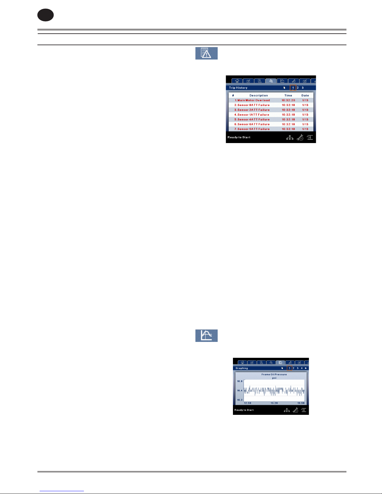
TRIP HISTORY
PAGES 1 TO A MAX OF 3
The pages in the Trips History folder document up to the last
15 trips that the controller has experienced, and time stamps
each. The trips are recorded in sequence, with number one
being the newest and 15 being the oldest. When a new trip
occurs, it becomes number one and all others are shifted up
in number.
The page numbers in the Title Bar are used to scroll through
the events, with each page displaying up to seven. Page
one displays events one through ve, page two displays six
through ten, and so on.
The following items will generate an entry in the trip history.
Trips
Active Trips will be highlighted in red while cleared Trips will
have red text.
The trip history also records compressor data at the time
of the trip to assist in diagnostics and troubleshooting.
Navigating to the trip entry and hitting the enter button will
bring up the trip history dialog box.
While the dialog box is active, press the left and right keys in
order to scroll through the displayed data. The name of the
trip will always be shown in the title bar of the dialog box.
Press enter when nished viewing the data to return to the
trip history screen
GRAPHING FOLDER
PAGES 1 THRU 5 – INDIVIDUAL GRAPHS
Variable (Read Only) Each page graphs one variable,
displaying the variable name and unit of measure in the top
center of the page. The variables that will be graphed on each
of the ve pages are selectable from page six. The units of
measure are selectable from the GENERAL SETTINGS folder.
Y-Axis (Read Only) is auto-scaling.
•
•
•
RECIPROCATING COMPRESSORS
80448905 Rev A 19
EN
X-Axis (Read Only - The time duration is selectable from
page six. The sample rate varies, based on the selected
duration.
The graph plots a minimum of 255 readings
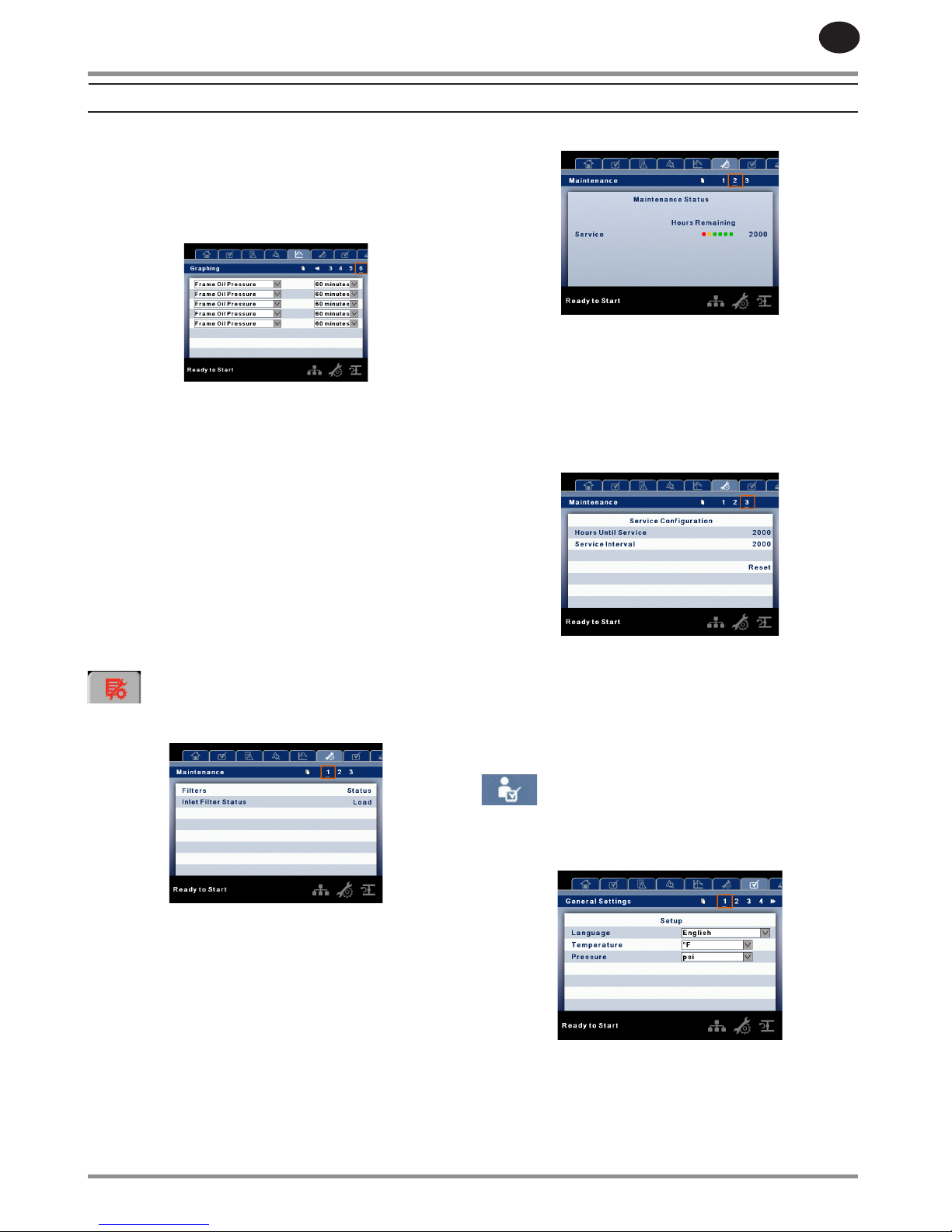
PAGE 6 – GRAPHING SELECTIONS
The selections for page one through ve are organized
sequentially in rows. The top row has page one selections and
the bottom row has page ve selections.
Variables - include all analog inputs as well as some
calculated variables. The amount of variables will vary
depending on the compressor type and the options it has.
Duration - selectable from the following ve times
10 minutes
30 minutes
60 minutes
12 hours
24 hours
These times are xed and cannot be changed.
MAINTENANCE FOLDER
PAGE 1 – FILTER STATUS
This page displays the status of the lters. The lter status will
either be “OK” or “Change” depending on the compressor’s
diagnostic readings. If a lter reaches the “change’ status, a
warning will be issued and the service indicator will light up
yellow to notify the user. Please note that the compressor
must be in a “Running Loaded” state to check these
maintenance items. If the compressor is not in a running state
– the status will display “Load,” unless a maintenance indicator
has been issued when the machine was running and has not
yet been reset.
The following lters are displayed:
Air Filter
•
•
•
•
•
•
•
•
PAGE 2 – MAINTENANCE STATUS
This page displays the time until the unit should be serviced.
The service meter will deplete as the hours count down closer
to a service appointment. Once the counter reaches the
yellow zone, the service indicator will light up yellow. Once
the counter reaches the red zone the service indicator will
light up red and maintenance must be performed.
PAGE 3 - MAINTENANCE CONFIGURATION
This page allows the user to set the service interval and to
reset the counter after the service has been performed.
The service interval may be set to any value between 1000
and 8000 hours, but must be set in accordance with the
factory maintenance schedule. After maintenance has been
performed, the user can reset the counter by navigating to
the Reset button and pressing the enter key.
GENERAL SETTINGS FOLDER
All parameters in the general settings folder are adjustable.
PAGE 1 – LANGUAGE SELECTION
•
•
•
RECIPROCATING COMPRESSORS
 Loading...