


Operating Instructions
COOKER
GB |
|
RS |
|
UA |
|
|
|
|
|
English, 1 РУССКИЙ,11 Украінська,23
RO
Română,34
GB
Contents
Installation, 2-5
Positioning and levelling
Electrical connections
Gas connection
Adapting to different types of gas
Technical data
Table of burner and nozzle specifications
KN1G2/UA
KNJ1G2/UA
KN1G20/UA
Description of the appliance, 6
Overall view Control panel
Start-up and use, 7-8
Using the hob
Using the oven
Oven cooking advice table
Precautions and tips, 9
General safety Disposal
Respecting and conserving the environment
Maintenance and care, 10
Switching the appliance off
Cleaning the appliance
Gas tap maintenance
Replacing the oven light bulb
Assistance
Installation
! Before operating your new appliance please read GB this instruction booklet carefully. It contains
important information concerning the safe installation and operation of the appliance.
!Please keep these operating instructions for future reference. Make sure that the instructions are kept with the appliance if it is sold, given away or moved.
!The appliance must be installed by a qualified professional according to the instructions provided.
!Any necessary adjustment or maintenance must be performed after the cooker has been disconnected from the electricity supply.
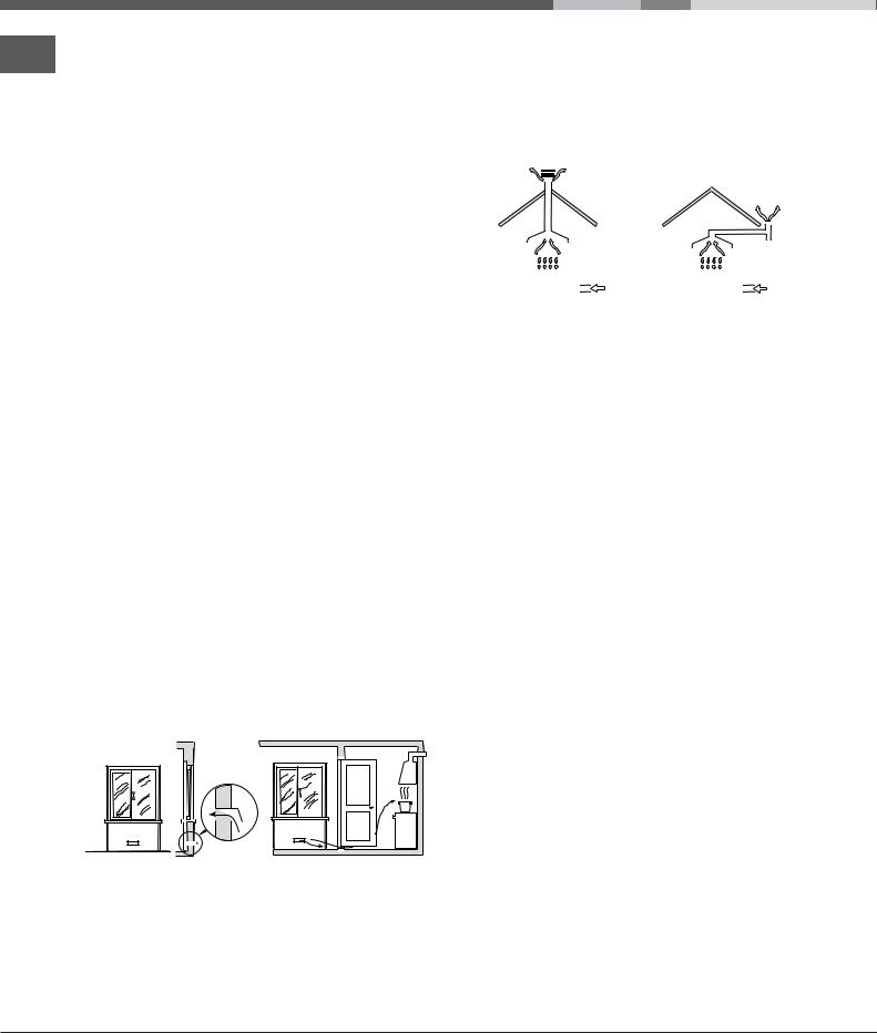
Room ventilation
The appliance may only be installed in permanentlyventilated rooms, according to current national legislation. The room in which the appliance is installed must be ventilated adequately so as to provide as much air as is needed by the normal gas combustion process (the flow of air must not be lower than 2 m3/h per kW of installed power).
The air inlets, protected by grilles, should have a duct with an inner cross section of at least 100 cm2 and should be positioned so that they are not liable to even partial obstruction (see figure A).
These inlets should be enlarged by 100% - with a minimum of 200 cm2 - whenever the surface of the hob is not equipped with a flame failure safety device. When the flow of air is provided in an indirect manner from adjacent rooms (see figure B), provided that these are not communal parts of a building, areas with increased fire hazards or bedrooms, the inlets should be fitted with a ventilation duct leading outside as described above.
|
|
|
|
|
|
|
|
|
|
|
Adjacent room |
Room requiring |
||
A |
|
|
|
|
|
|
|
|
|
|
B |
ventilation |
||
|
|
|
|
|
|
|
|
|
|
|
||||
|
|
|
|
|
|
|
|
|
|
|
|
|
|
|
|
|
|
|
|
|
|
|
|
|
|
|
|
|
|
|
|
|
|
|
|
|
|
|
|
|
|
|
|
|
|
|
|
|
|
|
|
|
|
|
|
|
|
|
|
|
|
|
|
|
|
|
|
|
|
|
|
|
|
|
|
|
|
|
|
|
|
|
|
|
|
|
|
|
|
|
|
|
|
|
|
|
|
|
|
|
|
|
|
|
A |
|
Ventilation opening for |
Increase in the gap between |
comburent air |
the door and the flooring |
! After prolonged use of the appliance, it is advisable to open a window or increase the speed of any fans used.
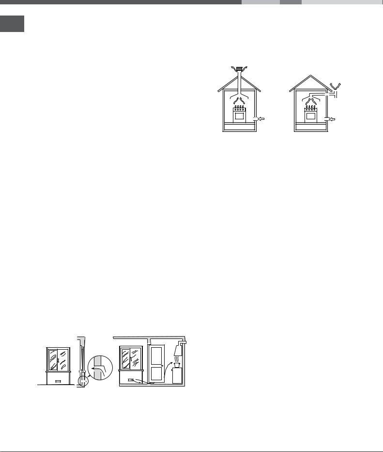
Disposing of combustion fumes
The disposal of combustion fumes should be guaranteed using a hood connected to a safe and efficient natural suction chimney, or using an electric fan that begins to operate automatically every time the appliance is switched on (see figure).
|
|
|
|
|
|
|
|
|
|
|
|
|
|
|
|
|
|
|
|
|
|
|
|
|
|
|
|
|
|
|
|
|
|
|
|
|
|
|
|
|
|
|
|
|
|
|
|
|
|
|
|
|
|
|
|
|
|
|
|
|
|
|
|
|
|
|
|
|
|
|
|
|
|
|
|
|
|
|
|
|
|
|
|
|
|
|
|
|
|
|
|
|
|
|
|
|
|
|
|
|
|
|
|
|
|
|
|
|
|
|
|
|
|
|
|
|
|
|
|
|
|
|
|
|
|
|
|
|
|
|
|
|
|
|
|
|
|
|
|
|
|
|
|
|
|
|
|
|
|
|
|
|
Fumes channelled |
|
Fumes channelled through |
||||||||||||||
straight outside |
|
a chimney or branched |
||||||||||||||
|
|
|
|
|
|
|
|
|
flue system reserved for |
|||||||
|
|
|
|
|
|
|
|
|
cooking appliances) |
|||||||
! The liquefied petroleum gases are heavier than air and collect by the floor, therefore all rooms containing LPG cylinders must have openings leading outside so that any leaked gas can escape easily.
LPG cylinders, therefore, whether partially or completely full, must not be installed or stored in rooms or storage areas that are below ground level (cellars, etc.). Only the
cylinder being used should be stored in the room; this should also be kept well away from sources of heat (ovens, chimneys, stoves) that may cause the temperature of the cylinder to rise above 50°C.
Positioning and levelling
!It is possible to install the appliance alongside cupboards whose height does not exceed that of the hob surface.
!Make sure that the wall in contact with the back of the appliance is made from a non-flammable, heatresistant material (T 90°C).
To install the appliance correctly:
•Place it in the kitchen, dining room or the bed-sit (not in the bathroom).
•If the top of the hob is higher than the cupboards, the appliance must be installed at least 200 mm away from them.
•If the cooker is installed underneath a wall cabinet, there must be a minimum distance of 420 mm between this cabinet and the top of the hob. This distance should be increased to 700 mm if the wall cabinets are flammable (see figure).
2

HOOD
|
Min. 600 mm. |
min. 650 mm. with hood min. 700 mm. without hood |
Min. 420 mm. |
Min. 420 mm. |
•Do not position blinds behind the cooker or less than 200 mm away from its sides.
•Any hoods must be installed according to the instructions listed in the relevant operating manual.
Levelling |
If it is necessary to level the appliance, screw the adjustable feet into the places provided on each corner of the base of the cooker (see figure).
The legs* fit into the slots on the underside of the base of the cooker.
Electrical connection
Install a standardised plug corresponding to the load indicated on the appliance data plate (see Technical data table).
The appliance must be directly connected to the mains using an omnipolar circuit-breaker with a minimum contact opening of 3 mm installed between the appliance and the mains. The circuit-breaker must be suitable for the charge indicated and must comply with NFC 15-100 regulations (the earthing wire must not be interrupted by the circuit-breaker). The supply cable must be positioned so that it does not come into contact with temperatures higher than 50°C at any point.
Before connecting the appliance to the power supply, make sure that:
•The appliance is earthed and the plug is compliant with the law.
•The socket can withstand the maximum power of the appliance, which is indicated by the data plate.
•The voltage is in the range between the values indicated on the data plate.
•The socket is compatible with the plug of the appliance. If the socket is incompatible with the plug, ask an authorised technician to replace it. Do not use extension cords or multiple sockets.
*Only available in certain models
! Once the appliance has been installed, the power
supply cable and the electrical socket must be GB easily accessible.
!The cable must not be bent or compressed.
!The cable must be checked regularly and replaced by authorised technicians only.
!The manufacturer declines any liability should these safety measures not be observed.
Gas connection
Connection to the gas network or to the gas cylinder may be carried out using a flexible rubber or steel hose, in accordance with current national legislation and after making sure that the appliance is suited to the type of gas with which it will be supplied (see the rating sticker on the cover: if this is not the case see below). When using liquid gas from a cylinder, install a pressure regulator which complies with current national regulations. To make connection easier, the gas supply may be turned sideways*: reverse the position of the hose holder with that of the cap and replace the gasket that is supplied with the appliance.
! Check that the pressure of the gas supply is consistent with the values indicated in the Table of burner and nozzle specifications (see below). This will ensure the safe operation and durability of your appliance while maintaining efficient energy consumption.
Gas connection using a flexible rubber hose
Make sure that the hose complies with current national legislation. The internal diameter of the hose must measure: 8 mm for liquid gas supply; 13 mm for methane gas supply.
Once the connection has been performed, make sure that the hose:
•Does not come into contact with any parts that reach temperatures of over 50°C.
•Is not subject to any pulling or twisting forces and that it is not kinked or bent.
•Does not come into contact with blades, sharp corners or moving parts and that it is not compressed.
•Is easy to inspect along its whole length so that its condition may be checked.
•Is shorter than 1500 mm.
•Fits firmly into place at both ends, where it will be fixed using clamps that comply with current regulations.
3
! If one or more of these conditions is not fulfilled or GB if the cooker must be installed according to the
conditions listed for class 2 - subclass 1 appliances (installed between two cupboards), the flexible steel hose must be used instead (see below).
Connecting a flexible jointless stainless steel pipe to a threaded attachment
Make sure that the hose and gaskets comply with current national legislation.
To begin using the hose, remove the hose holder on the appliance (the gas supply inlet on the appliance is a cylindrical threaded 1/2 gas male attachment).
! Perform the connection in such a way that the hose length does not exceed a maximum of 2 metres, making sure that the hose is not compressed and does not come into contact with moving parts.
Checking the connection for leaks
When the installation process is complete, check the hose fittings for leaks using a soapy solution. Never use a flame.
Adapting to different types of gas
It is possible to adapt the appliance to a type of gas other than the default type (this is indicated on the rating label on the cover).
Adapting the hob
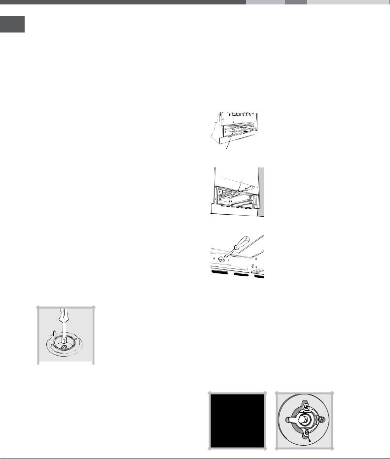
Replacing the nozzles for the hob burners:
1. Remove the hob grids and slide the burners off their seats.
2. Unscrew the nozzles using a
7 mm socket spanner (see
figure), and replace them with
nozzles suited to the new type
of gas(see Burner and nozzle
specifications table).
3. Replace all the components  by following the above instructions in reverse.
Adjusting the hob burners’ minimum setting:
1.Turn the tap to the minimum position.
2.Remove the knob and adjust the regulatory screw, which is positioned inside or next to the tap pin, until the flame is small but steady.
! If the appliance is connected to a liquid gas supply, the regulatory screw must be fastened as tightly as possible.
3. While the burner is alight, quickly change the position of the knob from minimum to maximum and vice versa several times, checking that the flame is not extinguished.
! The hob burners do not require primary air adjustment.
Adapting the oven
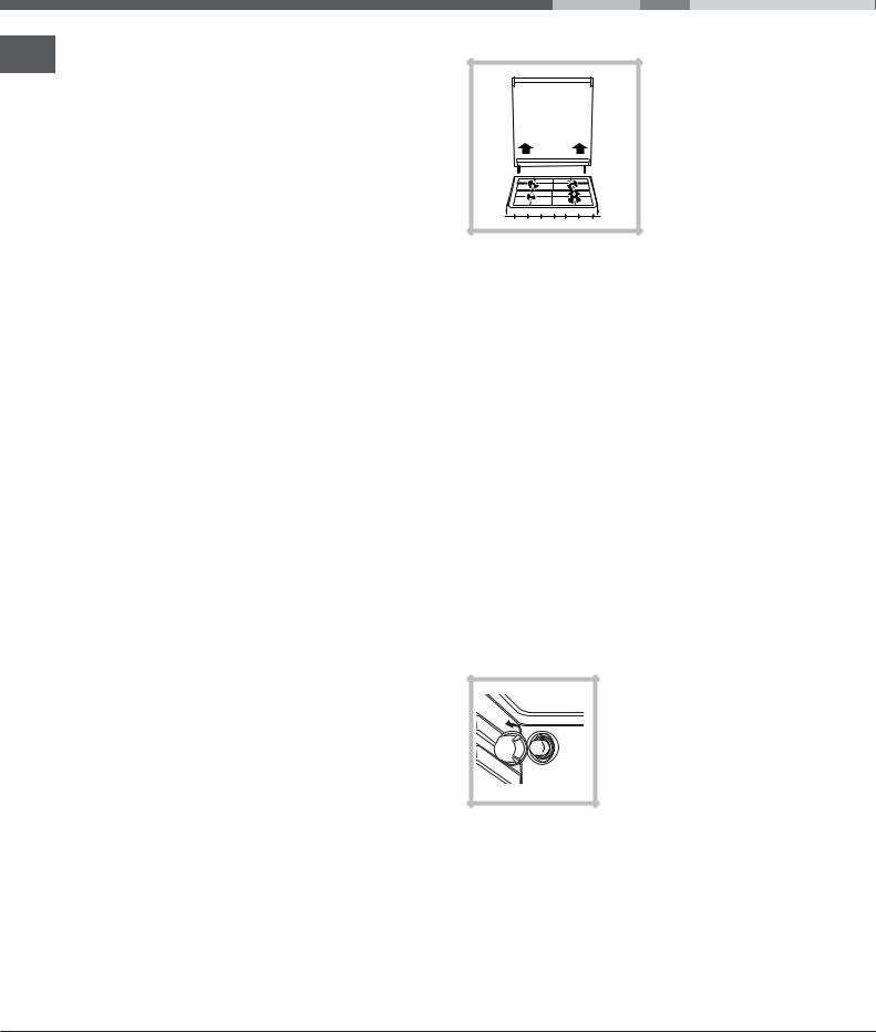
Replacing the oven burner nozzle: 1. Remove the oven compartment.
|
2. Slide out the protection |
|
|
|
panel A |
|
(see diagram). |
A |
|
|
3. Remove the oven burner |
|
|
|
|
V |
after unscrewing the screws V |
|
(see figure). |
|
The whole operation will be |
|
made easier if the oven door |
|
is removed. |
|
4. Unscrew the nozzle using a |
|
|
|
|
|
special nozzle socket spanner |
|
(see figure) or with a 7 mm |
|
socket spanner, and replace it |
|
with a new nozzle that is |
|
suited to the new type of gas |
|
(see Burner and nozzle |
|
specifications table). |
|
Adjusting the gas oven burner’s minimum setting:
1.Light the burner (see Start-up and Use).
2.Turn the knob to the minimum position (MIN) after it has been in the maximum position (MAX) for approximately 10 minutes.
3.Remove the knob.
4.Tighten or loosen the adjustment screws on the outside of the thermostat pin (see figure) until the flame is small but steady.
! If the appliance is connected to liquid gas, the adjustment screw must be fastened as tightly as possible.
4

5. Turn the knob from the MAX position to the MIN position quickly or open and shut the oven door, making sure that the burner is not extinguished.
We recommend cleaning the oven before using it for the first time, following the instructions provided in the "Care and maintenance" section.
TECHNICAL DATA |
GB |
|
Oven dimensions |
||
(HxWxD) |
34x39x38 cm |
|
|
||
Volume |
50 l |
|
Useful |
width 42 cm |
|
measurements |
||
depth 44 cm |
||
relating to the oven |
||
height 17 cm |
||
compartment |
||
|
||
Power supply voltage |
see data plate |
|
and frequency |
may be adapted for use with any |
|
|
||
|
type of gas shown on the data |
|
|
plate, which is located inside the |
|
Burners |
flap or, after the oven |
|
|
compartment has been opened, |
|
|
on the left-hand wall inside the |
|
|
oven. |
|
|
EC Directives: 2006/95/EC dated |
|
|
12/12/06 (Low Voltage) and |
|
|
subsequent amendments - |
|
|
2004/108/EC dated 15/12/04 |
|
|
(Electromagnetic Compatibility) |
|
|
and subsequent amendments - |
|
|
2009/142/EC dated 30/11/09 |
|
|
(Gas) and subsequent |
|
|
amendments - 93/68/EEC dated |
|
|
22/07/93 and subsequent |
|
|
amendments - 2002/96/EC. |
|
|
1275/2008 (Stand-by/ Off mode) |
Table of burner and nozzle specifications
|
|
|
|
|
|
|
|
|
|
|
|
|
|
|
|
||||
|
|
|
|
|
|
|
|
|
|
|
|
|
|
|
|
|
|
||
|
|
|
|
|
|
|
|
! "" |
# |
! "" |
|
# |
! "" |
|
# |
||||
|
|
|
|
|
|
|
|
$ |
|
|
|
|
|
|
|
||||
|
|
|
|
|
|
|
|
|
|
|
|
|
|
|
|
|
|
|
|
|
|
|
|
|
! |
|
% & & |
|
|
|
|
|
|
|
|
|
|
|
|
|
|
|
|
|
|
|
|
|
|
|
|
|
|
|
|
|
|
|
|
# |
|
|
|
( |
|
) |
+ |
26 |
: 2 |
|
: + |
6 |
|
:26 |
+( |
|
:26 |
||
'$% |
|
|
|
|
|
||||||||||||||
|
|
|
|
|
|
|
|
|
|
|
|
|
|
|
|
|
|
||
|
|
|
|
|
|
|
|
|
|
|
|
|
|
|
|
|
|
|
|
; # |
)> |
|
? |
|
+ |
( |
) |
(2 |
|
(6 |
6 |
|
2 |
2 |
|
2 |
|||
< & |
; |
|
|
|
|
|
|||||||||||||
|
|
|
|
|
|
|
|
|
|
|
|
|
|
|
|
|
|
||
|
|
|
|
|
|
|
|
|
|
|
|
|
|
|
|
|
|
|
|
@ D |
|
>> |
|
|
|
+ |
( |
> |
)( |
|
) |
)? |
|
?> |
2 |
|
?> |
||
; @ |
|
|
|
|
|
||||||||||||||
|
|
|
|
|
|
|
|
|
|
|
|
|
|
|
|
|
|
||
|
|
|
|
|
|
|
|
|
|
|
|
|
|
|
|
|
|
|
|
EF |
|
|
|
|
: |
|
|
+2 +? |
62 |
+> |
|
+( |
) |
|
? |
+ |
|
? |
|
|
|
|
|
|
|
|
|
|
|
|
|
|
|
|
|
|
|
|
|
; |
|
|
! |
|
|
G |
|
|
:2 ( |
|
() |
: |
|
( |
|
||||
|
|
< |
|
|
|
G |
|
|
: |
|
:> |
) |
|
6H> |
|
||||
|
|
|
|
|
|
|
|
||||||||||||
|
< D |
|
|
G |
|
|
(> |
|
+> |
:> |
|
2 |
|
||||||
|
|
|
|
|
|
|
|
||||||||||||
|
|
|
|
|
|
|
|
|
|
|
|
|
|
|
|
|
|
|
|
*At 15°C and 1013 mbardry gas
** |
Propane |
P.C.S. = 50,37 MJ/Kg |
*** |
Butane |
P.C.S. = 49,47 MJ/Kg |
|
Natural |
P.C.S. = 37,78 MJ/m3 |
S S 
A R
KN1G2/UA
KNJ1G2/UA
KN1G20/UA
5

Description of the appliance
Overall view
GB
Control panel
Electronic Lighting |
|
|
Button for Oven Light* |
|
|
|
||||||||
for Hob Burners* |
|
|
|
|
|
|
|
|
|
|
|
|
|
|
|
|
|
|
|
|
|
|
|
|
|
|
|
|
|
|
|
|
|
|
|
|
|
|
|
|
|
|
|
|
|
|
|
|
|
|
|
|
|
|
|
|
|
|
|
|
|
|
|
|
|
|
|
|
|
|
|
|
|
|
Hob BURNER control knobs
OVEN control knob
* Only available in certain models.
6

Start-up and use
Using the hob
Lighting the burners
For each BURNER knob there is a complete ring showing the strength of the flame for the relevant burner.
To light one of the burners on the hob:
1.Bring a flame or gas lighter close to the burner.
2.Press the BURNER knob and turn it in an anticlockwise direction so that it is pointing to the maximum flame setting E.
3.Adjust the intensity of the flame to the desired level by turning the BURNER knob in an anticlockwise direction. This may be the minimum setting C, the maximum setting E or any position in between the two.
|
|
If the appliance is fitted with |
|
X |
|
an electronic lighting |
|
|
device* (see figure), press |
||
|
|
||
|
|
the ignition button, marked |
|
|
|
with the symbol |
, then |
|
C |
hold the BURNER knob |
|
|
down and turn it in an |
||
|
|
||
anticlockwise direction, towards the maximum flame setting, until the burner is lit.
Several models are equipped with an ignition device which is built into the knob; in this case the electronic ignition device* is present (C) but the ignition button is not. Simply press the BURNER knob and turn it in an anticlockwise direction so that it is pointing to the maximum flame setting, until the burner is lit. The burner may be extinguished when the knob is released. If this occurs, repeat the operation, holding the knob down for a longer period of time.
! If the flame is accidentally extinguished, switch off the burner and wait for at least 1 minute before attempting to relight it.
If the appliance is equipped with a flame failure safety device*(X), press and hold the BURNER knob for approximately 2-3 seconds to keep the flame alight and to activate the device.
To switch the burner off, turn the knob until it reaches the stop position •.
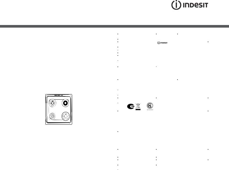
Practical advice on using the burners
For the burners to work in the most efficient way possible and to save on the amount of gas consumed, it is recommended that only pans that have a lid and a flat base are used. They should also be suited to the size of the burner.
|
|
|
|
GB |
|
|
|
|
|
|
|
|
|
|
|
||||
|
|
|
|
|
|
|
|
|
|
|
|
|
|
|
|
|
|
|
|
|
|
|
|
|
To identify the type of burner, please refer to the diagrams contained in the “Burner and nozzle specifications”.
Using the oven
!The first time you use your appliance, heat the empty oven with its door closed at its maximum temperature for at least half an hour. Ensure that the room is well ventilated before switching the oven off and opening the oven door. The appliance may emit a slightly unpleasant odour caused by protective substances used during the manufacturing process burning away.
!Before operating the product, remove all plastic film from the sides of the appliance.
!Never put objects directly on the bottom of the oven; this will avoid the enamel coating being damaged. Only use position 1 in the oven when cooking with the rotisserie spit.
Lighting the oven
To light the oven burner, apply
a lighted match or a lighter to
hole and while pressing in all
the way set the oven knob on
maximum E.
The burner can be used at
 maximum or intermediate settings. These settings, maximum E. and
minimum C are indicated on the knob, plus off,
identified by the symbol • and operative when this symbol points to the notch.
For the minimum to maximum settings turn the knob counter clockwise from “Off”.
To turn off the burner, turn the knob clockwise until it stops (corresponding again with setting •).
! The oven is fitted with a safety device and it is therefore necessary to hold the OVEN control knob down for approximately 6 seconds*.
* Only available in certain models.
7
! If the flame is accidentally extinguished, switch off GB the burner and wait for at least 1 minute before
attempting to relight the oven.
Oven light*
The light may be switched on at any moment by pressing the OVEN LIGHT button.
Timer*
To activate the Timer proceed as follows:
1.Turn the TIMER knob in a clockwise direction 4 for almost one complete revolution to set the buzzer.
2.Turn the TIMER knob in an anticlockwise direction 5 to set the desired length of time.
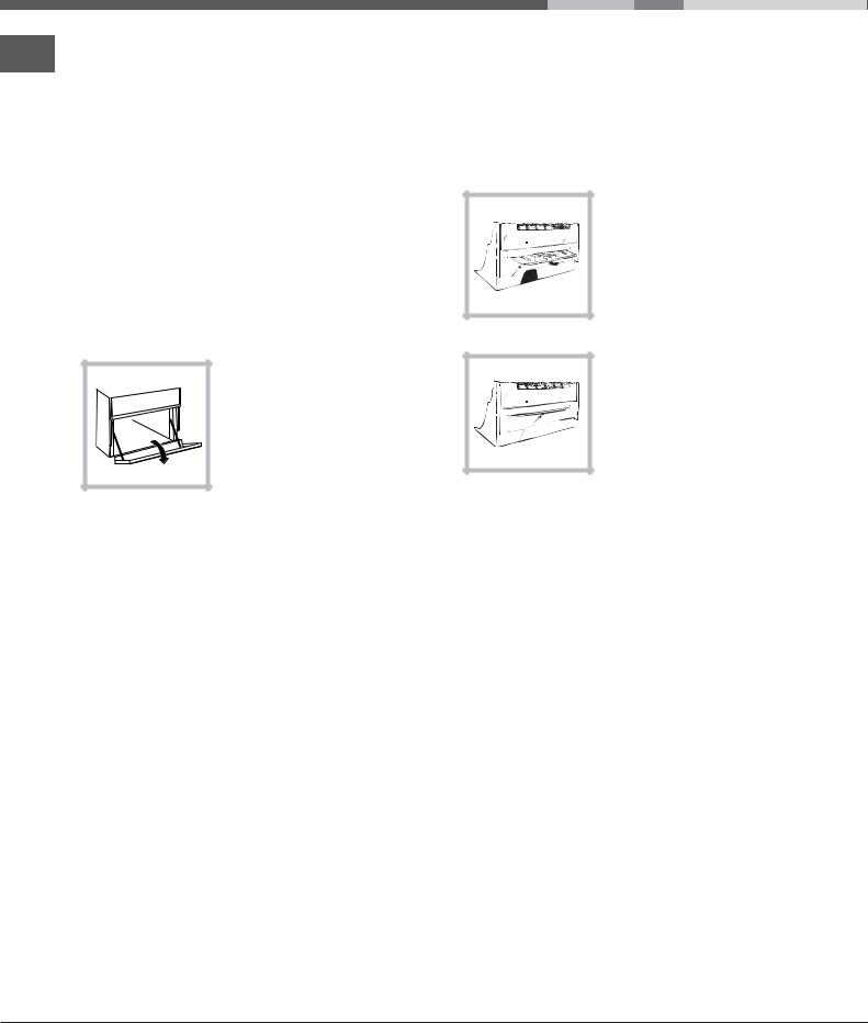
Lower compartment*
There is a compartment underneath the oven that may be used to store oven accessories or deep dishes. To open the door pull it downwards (see figure).
!The internal surfaces of the compartment (where present) may become hot.
!Do not place flammable materials in the lower oven compartment.
A
S 
In gas cooker models, there is a sliding protection layer A that shields the lower compartment from the heat generated by the burner (see figure).
To remove the sliding protection remove the screw S (see figure). To replace it, lock it in place with the screw S.
! Before using the oven make sure that the sliding protection is fixed correctly.
Oven cooking advice table
|
|
! " |
! |
% |
|
|
|
# $ " |
|||||
I |
LO |
|
|
|||
|
|
|||||
|
|
|
|
|
||
|
|
|
|
|
|
|
% |
|
|
|
|
|
|
|
|
|
|
|
|
|
O |
|
|
|
|
|
|
|
|
|
|
|
|
|
|
|
|
|
|
|
|
' |
|
|
|
|
|
|
Q |
|
|
|
|
! " |
|
O |
|
|
|
|
" |
|
|
! |
|
|
|
|
|
|
|
|
|
|
! |
|
|
|
|
|
|
! |
|
|
! |
|
|
|
" " |
|
|
|
|
|
|
|
|
# |
|
|
|
|
|
|
# |
|
|
! |
|
|
|
$ |
|
|
! |
|
|
|
% & ' ' |
|
|
! |
|
|
|
|
|
|
|
|
|
|
% (( |
|
|
|
|
|
|
( ' |
|
|
|
|
|
|
|
|
|
|
|
|
|
|
|
|
|
|
|
|
) |
|
|
! |
|
|
|
% |
|
|
! |
|
|
|
* + , ' |
|
|
! |
|
|
|
&O |
|
|
|
|
|
|
|
|
|
|
|
|
) ''$ & , + , & '
* Only available in certain models.
8
Precautions and tips
! This appliance has been designed and manufactured in compliance with international safety standards.
The following warnings are provided for safety reasons and must be read carefully.
General safety
•These instructions are only valid for the
countries whose symbols appear in the manual and on the serial number plate.•
The appliance was designed for domestic use inside the home and is not intended for commercial or industrial use.
•The appliance must not be installed outdoors, even in covered areas. It is extremely dangerous to leave the appliance exposed to rain and storms.
•Do not touch the appliance with bare feet or with wet or damp hands and feet.
•The appliance must be used by adults only for the preparation of food, in accordance with the instructions outlined in this booklet. Any other use of the appliance (e.g. for heating the room) constitutes improper use and is dangerous.
The manufacturer may not be held liable for any damage resulting from improper, incorrect and unreasonable use of the appliance.
•The instruction booklet accompanies a class 1 (insulated) or class 2 - subclass 1 (recessed between 2 cupboards) appliance.
•Keep children away from the oven.
•Make sure that the power supply cables of other electrical appliances do not come into contact with the hot parts of the oven.
•The openings used for the ventilation and dispersion of heat must never be covered.
•Do not close the glass hob cover (selected models only) when the burners are alight or when they are still hot.
•Always use oven gloves when placing cookware in the oven or when removing it.
•Do not use flammable liquids (alcohol, petrol, etc...) near the appliance while it is in use.
•Do not place flammable material in the lower storage compartment or in the oven itself. If the appliance is switched on accidentally, it could catch fire.
•Always make sure the knobs are in the • position and that the gas tap is closed when the appliance is not in use.
•When unplugging the appliance, always pull the plug from the mains socket; do not pull on the cable.
•Never perform any cleaning or maintenance work without having disconnected the appliance from the electricity mains.
• If the appliance breaks down, under no circumstances
should you attempt to repair the appliance yourself. GB Repairs carried out by inexperienced persons may cause
injury or further malfunctioning of the appliance. Contact Assistance.
•Do not rest heavy objects on the open oven door.
•The appliance should not be operated by people (including children) with reduced physical, sensory or mental capacities, by inexperienced individuals or by anyone who is not familiar with the product. These individuals should, at the very least, be supervised by someone who assumes responsibility for their safety or receive preliminary instructions relating to the operation of the appliance.
•Do not let children play with the appliance.
Disposal
•When disposing of packaging material: observe local legislation so that the packaging may be reused.
•The European Directive 2002/96/EC relating to Waste Electrical and Electronic Equipment (WEEE) states that household appliances should not be disposed of using the normal solid urban waste cycle. Exhausted appliances should be collected separately in order to optimise the cost of re-using and recycling the materials inside the machine, while preventing potential damage to the atmosphere and to public health. The crossed-out dustbin is marked on all products to remind the owner of their obligations regarding separated waste collection.
Exhausted appliances may be collected by the public waste collection service, taken to suitable collection areas in the area or, if permitted by current national legislation, they may be returned to the dealers as part of an exchange deal for a new equivalent product.
All major manufacturers of household appliances participate in the creation and organisation of systems for the collection and disposal of old and disused appliances.
Respecting and conserving the environment
•You can help to reduce the peak load of the electricity supply network companies by using the oven in the hours between late afternoon and the early hours of the morning.
•Check the door seals regularly and wipe them clean to ensure they are free of debris so that they adhere properly to the door, thus avoiding
heat dispersion.
9
Care and maintenance
Switching the appliance off
GB
Disconnect your appliance from the electricity supply before carrying out any work on it.
Cleaning the appliance
!Do not use abrasive or corrosive detergents such as stain removers, anti-rust products, powder detergents or sponges with abrasive surfaces: these may scratch the surface beyond repair.
!Never use steam cleaners or pressure cleaners on the appliance.
•It is usually sufficient simply to wash the hob using a damp sponge and dry it with absorbent kitchen roll.
•The stainless steel or enamel-coated external parts and the rubber seals may be cleaned using a sponge that has been soaked in lukewarm water and neutral soap. Use specialised products for the removal of stubborn stains. After cleaning, rinse well and dry thoroughly. Do not use abrasive powders or corrosive substances.
The cover
If the cooker is fitted with a glass cover, this cover
should be cleaned using lukewarm water. Do not use abrasive products.
It is possible to remove the
cover in order to make
cleaning the area behind
the hob easier. Open the
cover fully and pull it upwards (see figure).
! Do not close the cover when the burners are alight or when they are still hot.
Inspecting the oven seals
Check the door seals around the oven periodically. If the seals are damaged, please contact your nearest Authorised After-sales Service Centre. We recommend that the oven is not used until the seals have been replaced.
•The hob grids, burner caps, flame spreader rings and the hob burners can be removed
to make cleaning easier; wash them in hot water and non-abrasive detergent, making sure all burnt-on residue is removed before drying them thoroughly.
•For hobs with electronic ignition, the terminal part of the electronic lighting devices should be cleaned frequently and the gas outlet holes should be checked for blockages.
•The inside of the oven should ideally be cleaned after each use, while it is still lukewarm. Use hot water and detergent, then rinse well and dry with a soft cloth. Do not use abrasive products.
•Clean the glass part of the oven door using a sponge and a non-abrasive cleaning product, then dry thoroughly with a soft cloth. Do not use rough abrasive material or sharp metal scrapers as these could scratch the surface and cause the glass to crack.
•The accessories can be washed like everyday crockery, and are even dishwasher safe.
•Stainless steel can be marked by hard water that has been left on the surface for a long time, or by aggressive detergents containing phosphorus. After cleaning, rinse well and dry thoroughly. Any remaining drops of water should also be dried.
Gas tap maintenance
Over time, the taps may become jammed or difficult to turn. If this occurs, the tap must be replaced.
! This procedure must be performed by a qualified technician who has been authorised by the manufacturer.
Replacing the oven light bulb
1. After disconnecting the oven from the electricity mains, remove the glass lid covering the lamp socket (see figure).
2. Remove the light bulb and replace it with a similar one: voltage 230 V, wattage 25 W, cap
E14.
3.Replace the lid and reconnect the oven to the electricity supply.
Assistance
Please have the following information handy:
•The appliance model (Mod.).
•The serial number (S/N).
This information can be found on the data plate located on the appliance and/or on the packaging.
10
Руководствопо эксплуатации
RS
GB |
|
RS |
|
|
UA |
|
|
|
|
|
|
|
|
English, 1 |
РУССКИЙ,11 |
Украінська,23 |
||||
|
|
|
|
|
|
|
RO |
|
|
|
|
|
|
|
|
|
|
|
|
|
Română,34 |
|
|
|
|
|
|
KN1G2/UA
KNJ1G2/UA
KN1G20/UA
КУХОННАЯ ПЛИТА
Содержание
Монтаж, 12-15
Расположение и нивелировка Электрическое подсоединение Подсоединение к газопроводу Настроика на различные типы газа Технические данные
Таблица характеристик горелок и форсунок
Описание изделия,16
Общии вид Панель управления
Включение и эксплуатация,17-19
Эксплуатация варочнои панели Эксплуатация духового шкафа Таблица приготовления в духовом шкафу
Предосторожности и рекомендации,20
Общие требования к безопасности Утилизация
Экономия электроэнергии и охрана окружающеи среды
Техническое обслуживание и уход,21-22
Отключение электропитания Чистка изделия
Уход за рукоятками газовои варочнои панели Порядок замены лампочки в духовом шкафу Техническое обслуживание
Установка
! Важно сохранить данное руководство для его RS последующих консультации. В случае продажи, передачи или переезда проверьте, чтобы данное
руководство сопровождало изделие.
!Внимательно прочитаите инструкции: в них содержатся важные сведения об установке, эксплуатации и безопасности изделия.
!Установка изделия производится в соответствии с данными инструкциями квалифицированными специалистами.
!Любая операция по регуляции или техническому обслуживанию должна производиться только после отсоединения кухоннои плиты от сети электропитания.
Вентиляция помещении
Изделие может быть установлено в помещениях с постояннои вентиляциеи в соответствии с деиствующими национальными нормативами. В помещении, в котором устанавливается изделие, должен быть обеспечен приток воздуха в объеме, необходимом для оптимального горения газа (расход воздуха не должен быть меньше 2 м3/час на 1 кВт установленнои мощности). Вентиляционные отверстия, защищенные решетками, должны иметь воздуховод площадью не менее 100 мм2 полезного сечения и распологаться таким образом, чтобы их нельзя было закрыть, даже частично (см. рисунок А).
Эти отверстия должны быть увеличины на 100% - то есть иметь минимальную площадь 200 см2 - если варочная панель не оснащена предохранительным устроиством отсутствия пламени и если воздух в помещение поступает из смежных помещении (см. рисунок В) – при условии, что это не общая площадь здания, не пожароопасное помещение или спальня - оснащенных воздуховодом, выходящим на улицу, как описано выше.
A |
|
|
|
|
|
|
|
|
|
|
Смежное |
Вентилируемое |
||
|
|
|
|
|
|
|
|
|
|
B помещение |
помещение |
|||
|
|
|
|
|
|
|
|
|
|
|
|
|
|
|
|
|
|
|
|
|
|
|
|
|
|
|
|
|
|
|
|
|
|
|
|
|
|
|
|
|
|
|
|
|
|
|
|
|
|
|
|
|
|
|
|
|
|
|
|
|
|
|
|
|
|
|
|
|
|
|
|
|
|
|
A |
|
Вентиляционные |
Увеличение зазора между |
отверстия для притока |
дверью и полом |
воздуха |
|
! После продолжительного использования изделия рекомендуется открыть окно или включить более интенсивныи режим вентиляторов.
Дымоудаление
Дымоудаление должно осуществляться через вытяжноизонт, соединенныисэффективным дымоходом с натуральнои тягои, или посредством электровентилятора, которыиавтоматическивключается каждыи раз при включении изделия (см. рисунок).
Прямое Дымоудаление через камин или дымоудаление в дымоход с медным покрытием
атмосферу |
(для кухонных устроиств для |
|
приготовления пищи) |
! Сжиженные натуральные газы тяжелее воздуха, застиваются внизу, по этои причине помещения для хранения баллонов с СНГ должны иметь внетиляционные отверстия у пола для вентиляции возможных утечек газа.
Баллоны с СНГ, полные или частично израсходованные, не дожны размещаться или храниться в помещениях или хранилищах, расположенных в подземных помещениях (подвалы, и т.д.). Храните в помещении только рабочии баллон, установив его вдали от источников тепла (духовок, каминов, печеи), которые могут нагреть его до температуры выше 50°C.
Расположение и нивелировка
!Изделие может быть установлено рядом с кухонными элементами, высота которых не превышает поверхность варочнои панели.
!Проверьте, чтобы стена, к которои прилегает задняя часть изделия, была из невозгораемого материала и устоичивои к теплу (Т 90°C).
Порядок монтажа:
•изделие может быть установлено на кухне, в столовои или в однокомнатнои квартире (не в ваннои комнате);
•если варочная панель кухоннои плиты выше мебельных элементов, необходимо отодвинуть их от плиты на расстояние не менее 200 мм.
•если кухонная плита устанавливается под навесным шкафом, он должен располагаться на высоте не менее 420 мм от поверхности варочнои панели.
Это расстояние должно быть 700 мм, если навесные шкафы выполнены из возгораемого материала (см. рисунок);
•не заправляите занавески за кухонную плиту и не приближаите их на расстояние меньше 200 мм.
12

|
|
|
• возможная кухонная |
|
|
HOOD |
|
вытяжка должна быть |
|
|
Min. 600 mm. |
650mm.min.with hood 700withoutmm.min. hood |
установлена в |
|
420Min.mm. |
техническом |
|||
420Min.mm. |
||||
|
|
|
соответствии с |
|
|
|
|
инструкциями, |
|
|
|
|
приведенными в |
|
|
|
|
руководстве к вытяжке. |
Выравнивание |
При необходимости выровнять изделие вкрутите в специальные отверстия по углам в основании кухоннои плиты прилагающиеся регуляционные ножки (см.
рисунок).
Прилагающиеся ножки* вставляются под основание кухоннои плиты.
Электрическое подключение
Установите на кабель электропитания нормализованную штепсельную вилку, расчитанную на нагрузку, указанную на заводскои табличке изделия (см. табличку с техническими данными).
В случае прямого подключения к сети электропитания между кухоннои плитои и сетью необходимо установить мультиполярныи выключатель с минимальным расстоянием между контактами 3 мм, расчитанныи на данную нагрузку и соответствующии нормативу NFC 15-100 (выключатель не должен размыкать провод заземления). Кабельэлектропитаниядолженбыть расположен таким образом, чтобы ни в однои точке его температура не превышала температуру помещения болеечемна50°C.
Перед подсоединением кабеля проверьте следующее:
•электрическая розетка должна быть соединена с заземлением и соответствовать нормативам;
•электрическая розетка должна быть рассчитана на максимальную потребляемую мощность изделия, указанную на заводскои таблике;
•напряжение и частота тока сети должны соответствовать электрическим данным изделия;
•электрическая розетка должна быть совместима со штепсельнои вилкои изделия. В противном
*Имеется только в некоторых моделях
случае замените розетку или вилку; не |
RS |
используите удлинители или троиники. |
!Изделие должно быть установлено таким образом, чтобы электрическии кабель и электророзетка были легко доступны.
!Электрическии кабель изделия не должен быть согнут или сжат.
!Регулярно проверяите состояние кабеля электропитания и при необходимости поручаите
его замену только уполномоченным техникам.
! Фирма снимает с себя всякую ответственность в случае несоблюдения вышеописанных правил.
Подсоединение к газопроводу
Подсоединение к газопроводу или к газовому баллону выполняется посредством гибкого резинового или стального шланга в соответствии с деиствующими национальными нормативами, после проверки настроики изделия на тип используемого газа (см. этикетку настроики на крышке: в противном случае см. ниже). В случае использования сжиженного газа из баллона необходимо установить регуляторы давления, соответствующие деиствующему национальному нормативу. Для облегчения подсоединения газовыи патрубок является ориентируемым*: поменяите местами крепежную блокировочную гаику на заглушку и замените прилагающееся уплотнение.
! Для надежного функционирования, рационального использования энергии и более длительного срока службы изделия проверьте, чтобы давление подачи газа соответствовало значениям, указанным в таблице «Характеристики газовых конфорок и форсунок» (см. ниже).
Газовое подсоединение посредством резинового шланга
Проверьте, чтобы шланг соответствовал деиствующим национальным нормативам. Внутреннии диаметр шланга должен быть: 8 мм для сжижженного газа; 13 см для газа метана.
После подсоединения проверьте, чтобы шланг:
•не касался частеи, температура которых может превысить 50°C;
•не был растянут, перекручен, сжат или заломлен;
•не касался режущих предметов, острых углов, подвижных предметов и не был сжат;
•был легко доступен для проверки по всеи длине;
•не был длиннее 1500 мм;
•был прочно закреплен с обоих концов при помощи хомутов, соответствующих деиствующим национальным нормативам.
13

! Если одно или несколько из вышеописанных RS условии не будет соблюдено, и если кухонная плита устанавливается в условиях класса 2, подгруппа 1 (изделие, встроенное между двух
мебельных элементов), необходимо использовать гибкии стальнои шланг (см. ниже).
Газовое подсоединение посредством шланга из нержавеющеи стали со сплошнои оплеткои с резьбовыми соединениями.
Проверьте, чтобы шланг и уплотнения соответствовали деиствующим национальным нормативам.
Для подсоединения шланга снимите блокировочную гаику с изделия (патрубок подачи газа в изделие имеет цилиндрическу резьбу Ѕ газ «папа»).
! Длина подсоединяемого шланга не должна превышать 2 метра при максимальном растяжении. Проверьте, чтобы шланг не касался подвижных деталеи, которые могут его сжать.
Проверка уплотнения
По завершении подсоединения проверьте прочность уплотнения всех патрубков при помощи мыльного раствора, но никогда не пламенем.
Настроика на различные типы газа
Изделие может быть настроено на тип газа, отличающиися от оригинального (указан на этикетке настроики на крышке).
Настроика варочнои панели
Порядок замены форсунок конфорок на варочнои панели:
1. снимите решетки с варочнои панели и выньте горелки из своих гнезд;
2. отвинтитефорсункипри помощи полого гаечного ключа 7
мм (см. рисунок) и замените их на форсунки, расчитанные на
новыи тип газа (см. таблицу
Характеристики горелок и
форсунок);
3. восстановите на место все  комплектующие, выполняя
операции в обратном порядке по отношению к описанным выше.
Порядок регуляции минимального пламени конфорок на варочнои панели:
1.поверните рукоятку в положение минимального пламени;
2.снимите рукоятку и поверните регуляционныи винт,
расположенныи внутри или рядом со стержнем крана, вплоть до получения стабильного малого пламени.
! В случае использования сжиженного газа винт регуляции должен быть завинчен до упора.
3. проверьте, чтобы конфорка не гасла при резком повороте крана из положения максимального пламени в положение минимального пламени.
! Конфорки варочнои панели не нуждаются в какои-либо регуляции первичного воздуха.
Настроика духового шкафа
Замените форсунку газовои горелки духового шкафа: 1. выньте ящик для подогрева продуктов;  2. снимите выдвижную
панель А (см. рисунок);
A
3. выньте горелку из
V духового шкафа, сняв V- бразныи винт (см. рисунок); выполнение этои операции можно облегчить, сняв дверцу духового шкафа.
4. отвинтите форсунку горелки при помощи специального полого ключа для форсунок (см. рисунок) или полого ключа 7 мм и замените форсунку на новую, расчитанную на новыи тип газа (см. таблицу Характеристики горелок и форсунок).
Регуляция минимального пламени горелки духового шкафа:
1.включите горелку (см. Пуск и Эксплуатация);
2.оставьте рукоятку примерно в течение 10 минут в положении максимального пламени (МАКС), затем поверните ее в положение минимального пламени (МИН);
3.снимите рукоятку;
4.поверните регулировочныи винт, расположенныи внутри стержня термостата (см. рисунок), вплоть до
получения малого стабильного пламени.
! В случае использования сжиженного газа винт регуляции должен быть завинчен до упора;
14
5. проверьте, чтобы горелка не гасла при резком вращении рукоятки-регулятора из положения МАКС в положение МИН или при резком открывании или закрывании дверцы духовки.
Рекомендуем прочистить духовой шкаф перед началом его эксплуатации, следуя инструкциям, приведенным в параграфе «Обслуживание и уход».
S S 
A R
KN1G2/UA
KNJ1G2/UA
KN1G20/UA
Изделие: |
Комбинированная |
Газовая плита |
|
|
|
плита |
|
|
RS |
Торговая марка: |
|
|
|
|
Торговый знак изготовителя: |
|
|
|
|
|
|
|
|
|
|
|
|
|
|
Модель: |
KN1G2/UA; KNJ1G2/UA; KN1G20/UA |
|
|
|
Изготовитель: |
Indesit Company |
|
|
|
Страна-изготовитель: |
Польша |
|
|
|
Габаритные размеры духового |
34x39x38 см / 50 л |
|
|
|
шкафа / Объем: |
|
|
|
|
|
|
|
|
|
|
KN1G2/UA; |
KNJ1G2/UA; KN1G20/UA |
|
|
Номинальное значение |
|
|
|
|
|
|
|
|
|
напряжения электропитания или |
220-240 V ~ |
|
|
|
диапазон напряжения |
|
- |
|
|
|
|
|
|
|
|
|
|
|
|
Условное обозначение рода |
|
|
|
|
электрического тока или |
50/60Hz |
- |
|
|
номинальная частота |
|
|
||
|
|
|
|
|
переменного тока |
|
|
|
|
Класс зашиты от поражения |
Класс защиты I |
|
|
|
электрическим током |
|
|
|
|
|
|
|
|
|
Класс энергопотребления |
|
|
|
|
ТАБЛИЧКА С ЭЛЕКТРИЧЕСКИМИ |
|
|
|
|
ДАННЫМИ |
|
|
|
|
|
Директива ЕС: Директива ЕС: 2006/95/EC от |
|
|
|
|
12/12/06 (Низкое напряжение) с |
|
||
В случае необходимости |
|
|
||
последующими изменениями – 2004/108/ЕC от |
|
|
||
получения информации по |
|
|||
15/12/04 (Электромагнитная совместимость) с |
|
|
||
сертификатам соответствия или |
|
|||
последующими изменениями – 2009/142/ЕC от |
|
|
||
получения копий сертификатов |
|
|||
30/11/09 (Газ) - 90/68/СЕЕ от 22/07/93 с |
|
|
||
соответствия на данную технику, |
|
|||
последующими изменениями – 2002/96/ЕС. |
|
|||
Вы можете отправить запрос по |
1275/2008 (Stand-by/ Off mode) |
|
|
|
электронному адресу |
|
|||
|
|
|
|
|
cert.rus@indesit.com. |
|
|
|
|
Дату производства данной |
- 1-ая цифра в S/N соответствует последней |
|
|
|
техники можно получить из |
|
|||
цифре года, |
|
|
|
|
серийного номера, |
|
|
|
|
- 2-ая и 3-я цифры в S/N - порядковому номеру |
|
|
||
расположенного под штрих-кодом |
|
|||
(S/N XXXXXXXXX * |
месяца года, |
|
|
|
- 4-ая и 5-ая цифры в S/N - числу |
|
|
||
XXXXXXXXXXX), следующим |
|
|||
определенного месяца и года. |
|
|
||
образом: |
|
|||
|
|
|
|
|
Производитель: |
Indesit Company S.p.A. |
|
|
|
Виале А. Мерлони 47, 60044, Фабриано (АН), |
|
|||
|
Италия |
|
|
|
Импортер: |
ООО "Индезит РУС" |
|
|
|
|
до 01.01.2011: Россия, 129223, Москва, |
|
|
|
С вопросами (в России) |
Проспект Мира, ВВЦ, пав. 46 |
|
||
обращаться по адресу: |
с 01.01.2011: Россия, 127018, Москва, ул. |
|
|
|
|
Двинцев, дом 12, корп. 1 |
|
||
Таблица характеристик горелок и форсунок
|
|
|
|
|
|
|
Сжиженный газ |
|
|
|
|
Природный газ |
|
|
|
||
|
|
|
Мощность |
отверстие |
|
жиклер |
поток* |
жиклер |
|
поток* |
жиклер |
|
поток* |
|
|||
|
|
Диаметр, |
нагрева, |
|
|
|
|
||||||||||
|
Горелки |
1/100 |
|
1/100 |
|
г/ч |
1/100 |
|
л/ч |
1/100 |
|
л/ч |
|
||||
|
мм |
кВт (p.c.s.*) |
|
|
|
|
|
||||||||||
|
|
|
|
|
|
|
|
|
|
|
|
|
|
|
|||
|
|
|
номин. |
уменьш |
мм |
|
мм |
*** |
|
** |
мм |
|
|
мм |
|
|
|
|
Быстрая (большая) (R) |
100 |
3,00 |
0,7 |
41 |
|
86 |
218 |
|
214 |
116 |
|
286 |
143 |
|
286 |
|
|
Полубыстрая (средняя) (S) |
75 |
1,90 |
0,4 |
30 |
|
70 |
138 |
|
136 |
106 |
|
181 |
118 |
|
181 |
|
|
Вспомогательная |
55 |
1,00 |
0,4 |
30 |
|
50 |
73 |
|
71 |
79 |
|
95 |
80 |
|
95 |
|
|
(маленькая) (A) |
|
|
|
|
|
|||||||||||
|
|
|
|
|
|
|
|
|
|
|
|
|
|
|
|
|
|
|
Духовка |
- |
2,00 |
1,00 |
48/49 |
|
68 |
145 |
|
143 |
107 |
|
190 |
114 |
|
190 |
|
|
|
|
Номинальное (мбар) |
|
28-30 |
|
37 |
20 |
|
|
13 |
|
|||||
|
Давление |
|
Минимальное (мбар) |
|
20 |
|
25 |
17 |
|
|
6,5 |
|
|||||
|
|
|
Максимальное (мбар) |
|
35 |
|
45 |
25 |
|
|
18 |
|
|||||
* При 15°C и 1013 мбар – сухой газ *** Бутан P.C.S. = 49,47 Мдж/кг |
|
|
|
|
|
|
|
|
|
|
|
||||||
** Пропан P.C.S. = 50,37 Мдж/кг |
Натуральный P.C.S. = 37,78 Мдж/кг |
|
|
|
|
|
|
|
|
|
|
||||||
|
|
|
|
|
|
|
|
|
|
|
|
|
|
|
|
|
|
15
 Loading...