


 Loading...
Operator´s manual
Rider ProFlex 18 Rider ProFlex 21
Please read these instructions carefully and make sure you understand them before using the machine.
English

Svenska – 31
Operator’s Manual for
Rider ProFlex 18 and ProFlex 21
Contents |
|
Contents .................................................................. |
1 |
Introduction ............................................................ |
3 |
Congratulations ................................................... |
3 |
Driving and Transport on Public Roads .............. |
3 |
Towing ................................................................ |
3 |
Use ...................................................................... |
3 |
Proper Service .................................................... |
4 |
Serial Number ..................................................... |
4 |
Symbols and decals .............................................. |
5 |
Safety instructions ................................................. |
7 |
General use ........................................................ |
7 |
Driving on slopes ................................................ |
9 |
Children ............................................................. |
10 |
Maintenance ..................................................... |
10 |
Transport ........................................................... |
12 |
Presentation ......................................................... |
13 |
Placement of Controls ....................................... |
14 |
Throttle Control ................................................. |
15 |
Choke Lever ...................................................... |
15 |
Accelerator ........................................................ |
15 |
Cutting unit ........................................................ |
16 |
Accessories ....................................................... |
16 |
Lights and power outlet ..................................... |
16 |
Cutting height adjustment lever ........................ |
17 |
Lever for hydraulic lift of attachments, PF 21 |
....17 |
Mechanical lifting lever for cutting unit .............. |
18 |
Parking brake .................................................... |
19 |
Seat ................................................................... |
19 |
Fuelling ............................................................. |
19 |
Differential lock, PF 21 ...................................... |
20 |
Clutch control .................................................... |
20 |
Chronometer ..................................................... |
20 |
Mowing tips ....................................................... |
21 |
Clutch control .................................................... |
21 |
Driving ................................................................... |
22 |
Before Starting .................................................. |
22 |
Starting the engine ............................................ |
22 |
Driving the Rider, PF 18 .................................... |
24 |
Stopping the engine, PF 18 .............................. |
25 |
Driving the Rider, PF 21 .................................... |
26 |
Differential lock, PF 21 ...................................... |
27 |
Stopping the engine, PF 21 .............................. |
27 |
Maintenance ......................................................... |
29 |
Maintenance schedule ...................................... |
29 |
Removing the Rider’s covers ............................ |
32 |
Left-hand wing cover ......................................... |
33 |
Checking the engine’s cooling air intake ........... |
33 |
Cleaning the engine and muffler ....................... |
34 |
Checking the transmission air intake ................ |
34 |
Checking and adjusting the steering cables |
.....35 |
Checking and adjusting the throttle cable ......... |
36 |
Checking and adjusting the choke cable .......... |
36 |
Adjusting the differential lock, PF 21 ................. |
36 |
Adjusting the hydrostatic transmission cable |
....37 |
Cable holder ..................................................... |
37 |
Adjusting the parking brake .............................. |
38 |
Replacing the air filter ...................................... |
39 |
Replacing the fuel filter ..................................... |
42 |
Cleaning the pulse air filter ............................... |
42 |
Checking the fuel pump’s air filter .................... |
42 |
Checking the tyre pressures ............................ |
43 |
Checking the battery acid level ........................ |
43 |
Ignition system ................................................. |
43 |
Fuses ............................................................... |
44 |
Checking the safety system ............................. |
45 |
Replacing the light bulbs .................................. |
46 |
The cutting unit components ............................ |
47 |
Attaching the cutting unit .................................. |
47 |
Adjusting the cutting height, |
|
parallelism and ground pressure ...................... |
50 |
The cutting unit’s service position .................... |
51 |
Cutting unit model ............................................ |
52 |
Checking the blades ......................................... |
52 |
Removing the cutting unit ................................. |
53 |
Removing the unit frame .................................. |
55 |
Removing the belt ............................................ |
55 |
Attaching the belt ............................................. |
56 |
Changing the cutting unit’s belt ........................ |
57 |
Removal of BioClip Plug .................................. |
58 |
Lubrication ........................................................... |
59 |
Lubrication schedule, PF 18 ............................. |
59 |
Lubrication schedule, PF 21 ............................. |
60 |
General ............................................................ |
61 |
Lubricating the cables ...................................... |
61 |
Accessories ...................................................... |
61 |
Lubricating in accordance with |
|
the lubrication schedule ................................... |
62 |
1. Pedal mechanism in frame tunnel ................ |
62 |
2. Chains in the frame tunnel ........................... |
63 |
3. Differential lock cable, PF 21 ....................... |
63 |
4. Engine oil ..................................................... |
64 |
5. Gear lever .................................................... |
66 |
6. Transmission ................................................ |
66 |
7. Cutting unit ................................................... |
66 |
8. Driver’s seat ................................................. |
66 |
9. Throttle and choke cables, lever bearings |
... 67 |
10. Hydraulic oil filter, change, PF 21 .............. |
68 |
11. Oil filter, change ......................................... |
68 |
12. Parking Brake Cable .................................. |
69 |
13. Transmission oil level ................................. |
69 |
Trouble Shooting Guide ..................................... |
71 |
Storage ................................................................. |
73 |
Winter Storage ................................................. |
73 |
Service ............................................................. |
74 |
Electrical system ................................................. |
75 |
Hydraulic system, PF 21 ..................................... |
77 |
Technical data ..................................................... |
79 |
EU Declaration of Conformity ............................ |
81 |
EU Declaration of Conformity |
|
(only applies to Europe) ................................... |
81 |
Service journal .................................................... |
83 |
English-1

IMPORTANT INFORMATION
Read carefully through the operator’s manual so that you know how to use and maintain the Rider before you use it.
For service measures other than those described in this manual, please contact an authorised dealer that provides parts and service.
English-2

INTRODUCTION
Introduction
Congratulations
Thank you for purchasing a Husqvarna Rider. Husqvarna Riders have been designed according to a unique concept with a front mounted cutting unit and patented rear wheel steering. The Rider is built to give maximum efficiency even in small and confined areas. Collected controls and a hydrostatic transmission controlled by pedals also contribute to the machine’s performance.
This operator’s manual is a valuable document. Following the instructions (use, service, maintenance, etc.) can considerably increase the life span of your machine and even increase its resale value.
When you sell your Rider, make sure to give the operator’s manual to the new owner.
The final chapter of this operator’s manual comprises a Service Journal. Ensure that service and repair work is documented. A well-kept service journal reduces service costs for the season-based maintenance and affects the machine’s resale value. Take the operator’s manual along when the Rider is left to the workshop for service.
Driving and Transport on Public Roads
Check applicable road traffic regulations before driving and transport on public roads. You should always use approved fasteners during transport and ensure that the machine is well secured.
Towing
Rider ProFlex 18 and Rider ProFlex 21 are equipped with a hydrostatic power transmission and you should only tow the machine, if necessary, over very short distances and at a low speed otherwise there is a risk of damaging the hydrostatic power transmission.
The power transmission must be disengaged when towing, see “Clutch control” on page 21.
Use
This machine is constructed only for cutting grass on normal lawns and other free and even ground without obstacles such as stones, tree stubs, etc., even when the machine is equipped with special accessories provided by the manufacturer, for which the operating instructions are provided in conjunction with delivery. All other types of use are incorrect. The manufacturer’s instructions with regard to driving, maintenance, and repair must be followed precisely.
The machine may only be operated, maintained, and repaired by persons that are fully conversant with the machine’s special characteristics and safety regulations.
Accident prevention regulations, other general safety regulations, occupational safety rules, and traffic regulations must be observed.
Unauthorised modifications to the design of the machine may absolve the manufacturer from liability for any resulting personal injury or property damage.
English-3

INTRODUCTION
Proper Service
Husqvarna’s products are sold all over the world and only by specialised retail traders offering complete service. This ensures that you as a customer receive only the best support and service. Before the product is delivered, the machine has, for example, been inspected and adjusted by your retailer, see the certificate in the Service Journal in this operator’s manual.
When you need spare parts or support concerning service, warranty issues, etc., please consult the following professional:
|
|
|
This operator’s manual belongs to the |
Engine |
Transmission |
machine bearing serial number: |
|
|
|
|
|
Serial Number
The serial number can be found on the printed plate attached to the front, left-hand side under the seat. Stated on the plate, from the top, are:
•The machine’s type designation.
•The manufacturer’s type number.
•The machine’s serial number.
Please state the type designation and serial number when ordering spare parts.
The engine’s serial number is found on a barcode sticker. This is placed on the left side of the crankcase, in front of the starter. The sticker states:
•The engine’s serial number (E/NO).
•Code.
Please state these when ordering spare parts.
The transmission’s serial number is found on the barcode sticker located on the front of the housing on the left-hand drive shaft:
•The type designation is stated above the barcode and starts with the letter K.
•The serial number is stated above the barcode and has the prefix s/n.
•The manufacturer’s type number is stated under the barcode and has the prefix p/n. Please state the type designation and serial number when ordering spare parts.
English-4

EXPLANATION OF SYMBOLS
Symbols and decals
These symbols can be found on the Rider and in the operator’s manual.
Study them carefully so that you know what they mean.
Read the operator’s manual.
Reverse |
Neutral |
Fast |
Slow |
Engine off |
Battery |
Choke |
Fuel |
Oil level |
Cutting Height |
Reversing |
Forward |
Ignition |
|
|
|
|
Use hearing |
|
Hydrostatic free |
Parking |
Brake |
Warning |
protection |
|
wheeling |
brake |
|
|
|
|
|
|
|
|
Noise emission to surroundings in accordance with the directive of the European Community.
The machine’s emission is indicated in the TECHNICAL DATA chapter and on the decal.
Warning! Rotating |
Warning! Risk of the |
Never drive directly |
CE conformity |
blades |
Rider overturning |
across a slope |
marking |
Never carry passengers on the Rider or on its tools.
Never use the Rider if persons, especially children or pets, are in the immediate vicinity.
Starting instructions
Read the operator’s manual Check the engine oil level
Check the oil level in the hydrostat Lift up the cutting unit
Put the hydrostat pedals in the neutral position
Brake
Use the choke if the engine is cold Start the engine
Disengage the parking brake before driving
Do not insert your |
Drive very slowly |
hands or feet under |
without the cutting |
the cover when the |
unit. |
engine is running. |
|
Accelerator pedal forward
Neutral position
Accelerator pedal reversing
Switch off the engine and remove the ignition cable before carrying out repairs or maintenance
English-5

EXPLANATION OF SYMBOLS
WARNING!
XXXXXXX XXXX XXXXXXXX XXX X.
XXXXX XXXXXX XX.
XX XXXXXXXX XXXXX XXX XX.
Used in this publication to notify the reader of a risk of personal injury, particularly if the reader should neglect to follow instructions given in the manual.
IMPORTANT INFORMATION
Xxxxxxx xxxx xxxxxxxx xxx xxx xxxx xxxxxx xx.
Used in this publication to notify the reader of a risk of material damage, particularly if the reader should neglect to follow instructions given in the manual. Used also when there is a potential for misuse or misassembly.
Avoid hosing the decals with high pressure washers. Replace damaged decals before the machine is used.
English-6
SAFETY INSTRUCTIONS
Safety instructions
These instructions are for your safety. Read them carefully.
WARNING!
The inserted symbol means that important safety instructions needed to be observed. It applies to your safety.
General use
•Read all instructions in this operator’s manual and on the machine before starting it. Ensure you understand them and then observe them.
•Learn how to use the machine and its controls safely and learn how to stop quickly. Also learn to recognize the safety decals.
•Only allow the machine to be used by adults who are familiar with its use.
•Make sure nobody else is in the vicinity of the machine when you start the engine, engage the drive, or run the machine.
•Clear the area of objects such as stones, toys, steel wire, etc. that may become caught in the blades and be thrown out.
•Beware of the ejector and do not point it at any one.
•Stop the engine and prevent it from starting before you clean the cutting unit.
•Remember that the driver is responsible for dangers or accidents.
•Never take passengers. The machine is only intended to be used by one person.
•Always look down and behind before and during reversing manoeuvres. Keep watch for both large and small obstacles.
•Slow down before turning.
•Shut down the blades when not mowing.
•Be careful when rounding fixed objects, so that the blades do not hit them. Never run the machine over foreign objects.
WARNING!
This machine can sever hands and feet as well as throw objects. Failure to observe the safety instructions can result in serious injuries.
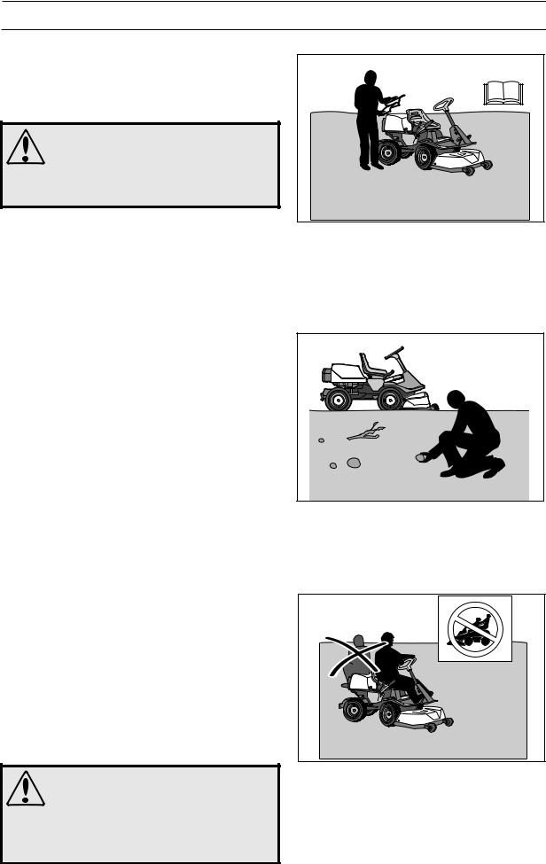
8010-047 |
Read the operator’s manual before starting the machine
6003-002
Clear the area of objects before mowing
8010-052 |
Never take passengers
English-7
SAFETY INSTRUCTIONS
WARNING!
Engine exhaust, some of its constituents and certain vehicle components contain or emit chemicals considered to cause cancer, birth defects or other reproductive impairment. The engine emits carbon monoxide, which is a colourless, poisonous gas. Do not use the machine in enclosed spaces.
•Only use the machine in daylight or in other well-lit conditions. Keep the machine at a safe distance from holes or other irregularities in the ground. Pay attention to other possible risks.
•Never use the machine if you are tired, if you have consumed alcohol, or if you are taking other drugs or medication that can affect your vision, judgment, or co-ordination.
•Beware of traffic when working near or crossing a road.
•Never leave the machine unsupervised with the engine running. Always stop the blades, apply the parking brake, stop the engine and remove the keys before leaving the machine.
•Never allow children or other persons not trained in the use of the machine to use or service it. Local laws may regulate the age of the user.
WARNING!
You must use approved personal protective equipment whenever you use the machine. Personal protective equipment cannot eliminate the risk of injury but it will reduce the degree of injury if an accident does happen. Ask your dealer for help in choosing the right equipment.
•Use hearing protection to minimise the risk of hearing impairment.
•Always wear approved protective glasses or a full visor when assembling or driving.
•Never wear loose clothing that can fasten in moving parts.
•Never use the machine when barefoot. Always wear protective shoes or protective boots, preferably with steel toe caps.
•Make sure that you have first aid equipment close at hand when using the machine.
English-8
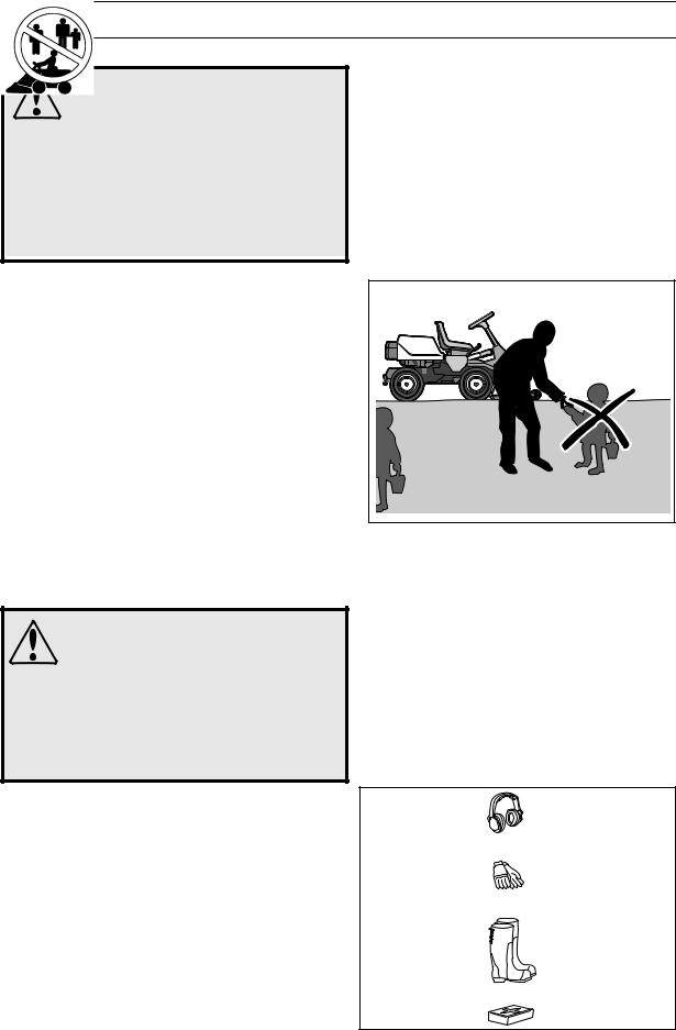
6003-006
Keep children away from the work area
8011-292
Personal protective equipment
SAFETY INSTRUCTIONS
Driving on slopes
Driving on slopes is one of the operations where the risk of the driver losing control of the machine or of it overturning is the greatest; this can result in serious injury or death. All slopes demand extra care. If you cannot reverse up a slope or if you feel unsure, do not mow it.
IMPORTANT INFORMATION
Do not drive down slopes with the unit raised.
Do as follows
•Remove obstacles such as stones, tree branches, etc.
•Mow up and down, not side-to-side.
•Never drive the machine on terrain that slopes more than 15°.
•Avoid starting or stopping on a slope. If the tyres start to slip, stop the blades and drive slowly down the slope.
•Always drive evenly and slowly on slopes.
•Make no sudden changes in speed or direction.
•Avoid unnecessary turns on slopes, and if it proves necessary, turn slowly and gradually downward,
if possible.
•Watch out for and avoid driving over furrows, holes, and bumps. It is easier for the machine to overturn on uneven ground. Tall grass can hide obstacles.
•Drive slowly. Do not turn the wheel sharply.
•Be extra cautious with any additional equipment, which can alter the machine’s stability.
•Do not mow near verges, ditches, or banks. The machine can suddenly overturn if one wheel comes over the edge of a steep slope or a ditch, or if an edge gives way.
•Do not mow wet grass. It is slippery, and tyres can lose their grip so that the machine skids.
•Try not to stabilise the machine by putting a foot on the ground.
•When cleaning the chassis, the machine may never be driven near verges or ditches.
•Follow the manufacturer’s recommendations regarding wheel weights or counterbalance weights to increase machine stability.
IMPORTANT INFORMATION
Wheel weights fitted on the rear wheels are recommended when driving on slopes for safer steering and improved manoeuvrability. Consult your dealer concerning the use of wheel weights if you are unsure.
6003-004 |
Mow upwards and downwards on slopes, not sideways
|
8010-054 |
Be |
slopes |
English-9

SAFETY INSTRUCTIONS
Children
• Serious accidents may occur if you fail to be observant for children in the vicinity of the machine. Children are often attracted to the machine and mowing. Never assume that children will stay where you last saw them.
• Keep children away from the mowing area and under close supervision by another adult.
• Keep an eye out and shut off the machine if children enter the work area.
•Before and during a reversing manoeuvre, look
backward and downward for small children. |
8010-057 |
|
Never allow children to operate the machine
•Never allow a child to ride with you. They can fall off and seriously injure themselves or be in the way for safe manoeuvring of the machine.
•Never allow children to operate the machine.
•Be particularly careful near corners, bushes, trees or other objects that block your view.
Maintenance
•Stop the engine. Prevent the engine from starting by removing the spark plug cables from the spark plugs or by removing the ignition key before making any adjustments or performing maintenance.
•Never fill the fuel tank indoors.
•Petrol and petrol fumes are poisonous and extremely flammable. Be especially careful when handling petrol, as carelessness can result in personal injury or fire.
•Only store fuel in containers approved for the purpose.
•Never remove the fuel cap or fill the fuel tank while the engine is running.
•Allow the engine to cool before refuelling. Do not smoke. Do not fill petrol in the vicinity of sparks or naked flames.
•Handle oil, oil filters, fuel and battery carefully, of environmental considerations. Observe applicable recyling regulations.
•Electrical shocks can cause injuries. Do not touch cables when the engine is running. Do not test the ignition system with your fingers.
8010-058 |
Never fill the fuel tank indoors
English-10
SAFETY INSTRUCTIONS
WARNING!
The engine and components of the exhaust and hydraulic systems become extremely hot during operation. Risk of burn injuries if touched.
•If leaks arise in the fuel system, the engine must not be started until the problem has been resolved.
•Store the machine and fuel in such a way that there is no risk of leaking fuel or fuel vapour leading to damages.
•Check the fuel level before each use and leave space for the fuel to expand, because the heat from the engine and the sun may otherwise cause the fuel to expand and overflow.
•Avoid overfilling. If you spill petrol on the machine, wipe up the spill and wait until it has evaporated before starting the engine. If you spill petrol on your clothing, change your clothing.
•Allow the machine to cool before taking any actions in the engine room.
WARNING!
The battery contains lead and lead compounds, chemicals that are considered to cause cancer, birth defects, and other reproductive impairment. Wash you hands after touching the battery.
•Be especially careful when handling battery acid. Acid on the skin can cause serious corrosive injuries. In the event of spillage on the skin wash immediately with water.
•Acid in the eyes can cause blindness, contact a doctor immediately.
•Be careful when servicing the battery. Explosive gases form in the battery. Never perform maintenance on the battery while smoking or in the vicinity of open flames or sparks. This can cause the battery to explode and cause serious injuries.
•Make sure all nuts and screws are tightened correctly and that the equipment is in good condition.
•Do not modify safety equipment. Check regularly to be sure it works properly. The machine must not be driven if protective plates, protective covers, safety switches or other protective devices are not fitted or are defective.
•Do not change the settings of governors and avoid running the engine with overly high engine speeds. If you run too fast, you risk damaging the machine components.
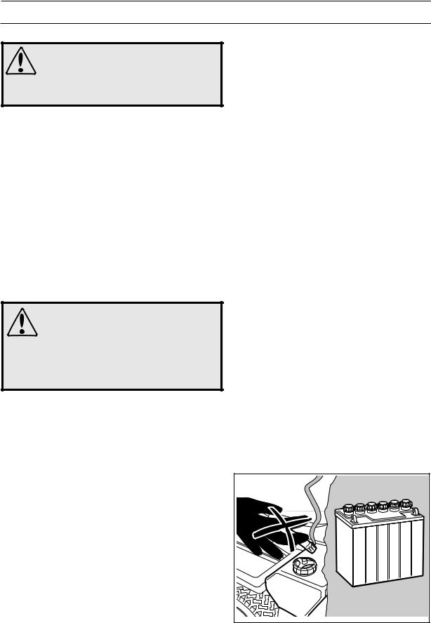
6003-009 |
Do not smoke when carrying out maintenance
English-11

SAFETY INSTRUCTIONS
•Never use the machine indoors or in spaces lacking proper ventilation. Exhaust fumes contain carbon monoxide, an odourless, poisonous and highly dangerous gas.
•Stop and inspect the equipment if you run over or into anything. If necessary, make repairs before starting.
•Never make adjustments with the engine running.
•The machine is tested and approved only with the equipment originally provided or recommended by the manufacturer.
•The blades are sharp and can cause cuts and gashes. Wrap the blades or wear protective gloves when handling them.
•Check the parking brake’s functionality regularly. Adjust and maintain as required.
•The mulching unit should only be used where better quality mowing is required and in known areas.
•Reduce the risk of fire by removing grass, leaves and other debris that may have fastened in the machine. Allow the machine to cool before putting it in storage.
Transport
IMPORTANT INFORMATION
The parking brake is not sufficient to lock the machine during transport. Ensure you secure the machine firmly to the transporting vehicle.
•The machine is heavy and can cause serious crush injuries. Be especially careful when it is loaded in or out of a car or on and off of a trailer.
•Use an approved trailer to transport the machine. Activate the parking brake and secure the machine using approved fasteners, such as straps, chains or ropes when transporting.
•Check and abide by local traffic regulations before transporting or driving the machine on any road.
8009-467 |
Never drive the machine in an enclosed space
8010-061 |
Regularly clean grass, leaves and other debris from the machine
English-12

PRESENTATION
Presentation
Congratulations on your choice of an exceptionally high quality product. This operator’s manual describes Rider ProFlex 18 and Rider ProFlex 21.
Rider ProFlex 18 is fitted with a Kawasaki four-stroke V-Twin engine developing 18 horse power.
Rider ProFlex 21 is fitted with a Kawasaki four-stroke V-Twin engine developing 21 horse power.
Rider ProFlex 21 is equipped with servo steering and hydraulic lifts, powered by the gearbox and differential lock.
The power transmission from the engine on both machines is handled by a hydrostatic gearbox, which allows variable variation of the speed by using the pedals. One pedal to drive forwards and one pedal to reverse.
Both Rider ProFlex 18 and ProFlex 21 are equipped with lights.
8009-551 |
ProFlex 18
8009-552 |
ProFlex 21
English-13
PRESENTATION
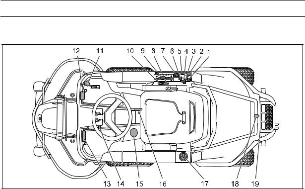
Placement of Controls
8009-530 |
1. |
Power outlet |
11. |
Accelerator for reversing |
2. |
Ignition key |
12. |
Accelerator for driving forwards |
3. |
Switch for the power outlet |
13. |
Pedal for parking brake |
4. |
Choke Lever |
14. |
Lock button for parking brake |
5. |
Switch for the lights |
15. |
Differential lock pedal, PF 21 |
6. |
Throttle - regulates the engine speed |
16. |
Lever for setting of seat |
7. |
Chronometer |
17. |
Fuel cap |
8. |
Lever for hydraulic lift of attachments |
18. |
Hood lock |
9. |
Cutting Height Adjustment Lever |
19. |
Clutch control |
10.Mechanical lifting lever with locking button for attachments
English-14

PRESENTATION
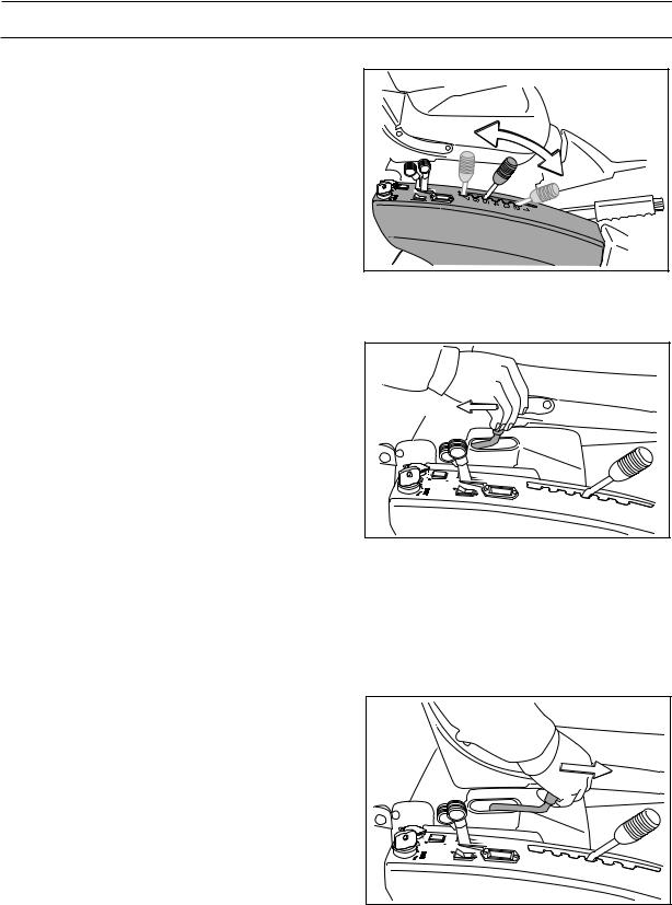
Throttle Control
The throttle is used to control the speed of the engine and thereby also the rotation speed of the blades.
In order to increase or decrease the engine speed, the control is moved forwards or backwards respectively.
Avoid idling the engine for long periods, as there is a risk of carbon build-up on the spark plugs.
Choke Lever
The choke lever is used for cold starts in order to provide the engine with a richer fuel mixture.
For cold starts, the lever shall be moved backwards to its endpoint.
8009-533 |
8009-534 |
Accelerator
The speed of the machine is variably controlled using two pedals. Pedal (1) is used to travel forwards and pedal (2) to reverse.
WARNING!
Make sure that no branches can interfere with the pedals when mowing under bushes.
1 |
2 |
6004-206 |
English-15

PRESENTATION
Cutting unit
Rider ProFlex can be equipped with a cutting unit of the types Combi 112 with a 112 cm cutting width and Combi 122 with a 122 cm cutting width.
The Combi unit functions as a BioClip unit when a BioClip plug is fitted, but can be set to rear ejection by removing the BioClip plug.
The unit’s BioClip function finely chops the grass several times before returning it to the lawn as fertiliser. The rear ejector ejects the clippings behind the unit without finely chopping them.
Accessories
The accessories are described in separate operator’s manuals. Contact your dealer if you require an accessory.
A selection of the available Rider ProFlex accessories:
•Brush
•Snow Blade
•Wheel Weights
•Snow Chains
•Dutch Hoe
•Edge Trimmer
•Gravel Harrow
•Trailer
•Spreader
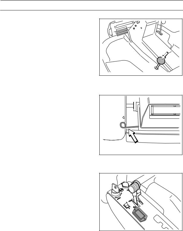
Lights and power outlet
The lights are switched on and off using power switch
(1) on the control panel.
A seat heater or mobile phone charger are examples of articles that can be connected to the power socket (2). The power outlet is switched on and off using power switch (3) on the control panel. The voltage is 12 volts.
1 |
2 |
3 |
8009-546 |
English-16
PRESENTATION
Cutting height adjustment lever
Using the cutting height lever, the cutting height can be adjusted between 7 different positions.
In order to obtain an equal cutting height, it is important that the air pressure is the same in both front wheels (60 kPa).
8009-557 |
Lever for hydraulic lift of attachments, PF 21
The lifting lever is used to put the cutting unit in either the transport or mowing position when hydraulic pressure is available.
In the transport position, the blade brake is automatically activated so that the blades stop within about 5 seconds.
Lifting the cutting unit (transport position)
Pull the lever backwards to engage the transport position.
The unit is raised and the blades stop rotating.
Secure the cutting unit if necessary using the mechanical lifting lever.
8009-536 |
Raising the cutting unit with the hydraulic lifting lever
Lowering the unit (mowing position)
If the cutting unit is secured in the transport position using the mechanical lifting lever, move the mechanical lifting lever to the cutting position.
Move the hydraulic lifting lever forwards to engage the cutting position. The unit is lowered and the blades begin to rotate.
In order to ensure that the hydraulic cylinder is in the outer position, hold the lever in the forward position for a half to one second.
8009-538 |
Lowering the unit with the hydraulic lifting lever
English-17

PRESENTATION
Mechanical lifting lever for cutting unit
The lever is used as a backup lever to put the cutting unit in either the transport or mowing position when hydraulic pressure is unavailable. It can also be used to mechanically secure the cutting unit in the transport position.
The lever must be used when starting the engine, if the engine stopped with the unit in the mowing position, in order to raise the unit so that the start lock circuit is disengaged.
In the transport position, the blade brake is automatically activated so that the blades stop within about 5 seconds.
Transport position
Pull the lever backwards to the locked position to engage the transport position.
The unit is raised and the blades stop rotating.
Mowing position
Depress the lock button and move the lever forwards to engage the mowing position.
The unit is lowered and the blades begin to rotate.
English-18
8009-554 |
Raising the cutting unit with the mechanical lifting lever
8009-555 |
Lowering the unit with the mechanical lifting lever
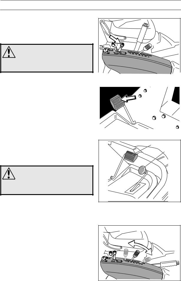
PRESENTATION
Parking brake
The parking brake is activated as follows:
1.Press the brake pedal.
2.Completely depress the lock button on the steering servo housing.
3.Release the brake pedal while keeping the button pressed in.
The parking brake lock is automatically disengaged when the brake pedal is pressed down.
Seat
The seat has a hinged mounting on the front edge and can be tipped forwards.
The seat can also be adjusted lengthways.
When making adjustments, the lever under the front edge of the seat is moved to the left, after which the seat can be moved backwards or forwards to the desired position.
8009-328 |
8009-548 |
Fuelling
The engine should be run on a minimum of 87-octane unleaded petrol (no oil mix). It can be beneficial to use environmentally adapted alkylate petrol. See also “Technical Data” concerning methanol and ethanol fuels.
Do not fill the tank completely, leave an expansion area of at least 2.5 cm (1").
WARNING!
Petrol is highly flammable. Observe caution and fill the tank outdoors, (see the safety instructions).
8009-330 |
English-19
PRESENTATION
Differential lock, PF 21
The differential lock couples the two drive wheels so that one wheel does not spin, thereby improving manoeuvrability.
Press the pedal to engage the differential lock.
6007-216 |
Clutch control
The clutch control is used to move the Rider when the engine is not running.
•Control drawn out, drive system disengaged.
•Control depressed, drive system engaged.
Chronometer
The chronometer shows how many hours the engine has been running. Any time when the engine is not running but the ignition is switched on is not registered. The last digit shows tenths of an hour (6 minutes).
8009-142
8009-567
English-20
DRIVING
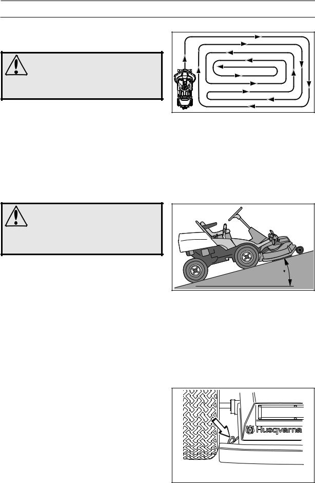
Mowing tips
WARNING!
Clear the lawn of stones and other objects that can be thrown out by the blades.
•Localise and mark rocks and other fixed objects in order to avoid collisions.
6007-212 |
Mowing patterns
• Begin with a high cutting height and reduce it until the desired mowing result is attained.
• The best mowing result will be obtained at a high engine speed (the blades rotate rapidly) and low speed (the Rider moves slowly). If the grass is not too long and thick the driving speed can be increased without significantly impairing the mowing result.
WARNING! |
|
|
Never drive the Rider on terrain that |
|
|
slopes more than 15°. Mow upwards and |
|
|
downwards on slopes, never sideways. |
|
|
Avoid sudden changes in direction. |
|
|
• The finest lawns are obtained by mowing often. |
|
|
Mowing will be more even and the clippings will be |
MAX 15 |
|
more evenly distributed across the area. The overall |
||
|
||
mowing time will not be longer as higher driving |
|
|
speeds can be selected without impairing the |
6016-104 |
|
|
||
mowing result. |
|
•Avoid mowing wet lawns. The mowing result will be poorer as the wheels will sink into the soft lawn.
•Hose beneath the cutting unit with water after each use. When cleaning, the cutting unit should be moved into the service position.
•It is important to mow frequently when mowing with the mulching function.
Clutch control
The clutch control must be pulled out in order for the Rider to be moved when the engine is shut off.
8009-337 |
English-21

DRIVING
Driving
IMPORTANT INFORMATION
The air intake grille in the engine cover behind the driver's seat must not be blocked by, for example, clothing, leaves, grass or dirt.
Impaired cooling of the engine. Risk of major engine damage.
Before Starting
•Read section “Safety instructions” on page 7 and “Presentation” on page 13.
•Carry out daily maintenance according to “Maintenance schedule” on page 29).
•Adjust the seat to the desired position.
Starting the engine
1.Raise the cutting unit by pulling the mechanical lifting lever backwards to the locked position (transport position).
8009-489 |
8009-554 |
2. Apply the parking brake by holding down the pedal and at the same time press in the release button.
8009-328
3.Move the throttle to the middle position.
8009-562
English-22

DRIVING
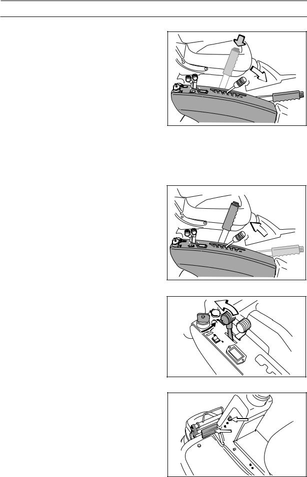
4.If the engine is cold, the choke control shall be moved backwards to its end position.
8009-534 |
5.Turn the ignition key to the start position.
6.When the engine starts, immediately release the ignition key so that it returns to the neutral position.
IMPORTANT INFORMATION
Do not run the starter motor for more than
5 seconds at a time. If the engine does not start wait about 15 seconds before trying again.
8009-558
8009-559
7.Move the choke lever gradually forward once the
engine has started.
8009-560
English-23
DRIVING
8.Set the desired engine speed with the throttle.
Allow the engine to run at a moderate speed, “half throttle”, for 3-5 minutes before loading it too heavily.
WARNING!
Never run the engine indoors, in enclosed or badly ventilated areas. Engine exhaust fumes contain poisonous carbon monoxide.
Driving the Rider, PF 18
1.Release the parking brake by first pressing the brake pedal and then releasing it.
2.Carefully press down one of the pedals until the required speed is attained.
Pedal (1) is pressed down to travel forwards and pedal (2) to reverse.
WARNING!
Never run the engine indoors, in enclosed or badly ventilated areas. Engine exhaust fumes contain poisonous carbon monoxide.
3.Select the required cutting height (1-7) using the cutting height lever.
8009-533 |
6007-208 |
1 |
2 |
6007-209 |
8009-557 |
English-24
DRIVING
4.Depress the lock button on the mechanical lifting lever and move the lever to its most forward position. The cutting unit lowers and starts.
8009-555 |
Stopping the engine, PF 18
If the engine has been worked hard, it is preferable to let the engine idle for a minute so it runs at its normal working temperature when stopped. Avoid idling the engine for long periods, as there is a risk of carbon build-up on the spark plugs.
1.Raise and secure the cutting unit by pulling the mechanical lifting lever backwards to the locked position.
If the cutting unit is left in the lower position, the start lock circuit will prevent you starting the engine.
8009-554 |
2. Move the throttle control to the “MIN” position. Turn the ignition key to “STOP”.
8009-561
3. When the machine is at a standstill apply the parking brake by holding down the pedal and at the same time press in the release button.
8009-328
English-25

DRIVING
Driving the Rider, PF 21
1.Release the parking brake by first pressing the brake pedal and then releasing it.
2.Carefully press down one of the pedals until the required speed is attained.
Pedal (1) is pressed down to travel forwards and pedal (2) to reverse.
WARNING!
Never run the engine indoors, in enclosed or badly ventilated areas. Engine exhaust fumes contain poisonous carbon monoxide.
3.Select the required cutting height (1-7) using the cutting height lever.
6007-208 |
1 |
2 |
6007-209 |
8009-539 |
4.Depress the lock button on the mechanical lifting lever and move the lever to its most forward position. The cutting unit lowers and starts.
8009-537 |
English-26

DRIVING
5.If the cutting unit does not lower completely, or if the blades do not rotate, lower the cutting unit completely using the hydraulic lifting lever.
In order to ensure that the hydraulic cylinder is in the outer position, hold the lever in the forward position for a half to one second.
8009-538 |
Differential lock, PF 21
The differential lock can be used during operation via the pedal on the left side.
In order not to get stuck, one can engage it shortly before the obstacle.
1.Engage the differential lock when necessary by pressing the pedal. If a wheel spins, let the drive pedal up a little.
2.Ensure that the differential lock is disengaged when the pedal is released. Use small steering movements or reverse a little until the pedal returns to its normal position.
Stopping the engine, PF 21
If the engine has been worked hard, it is preferable to let the engine idle for a minute so it runs at its normal working temperature when stopped. Avoid idling the engine for long periods, as there is a risk of carbon build-up on the spark plugs.
1.Lift the cutting unit with the hydraulic lifting lever.
6020-009 |
8009-536 |
The unit can then be secured in the raised position if necessary by moving the mechanical lifting lever backwards to the lock position.
If the cutting unit is left in the lower position, the start lock circuit will prevent you starting the engine.
8009-535 |
English-27 |
Loading...