


 Loading...
Operator′s manual
PR 17 PR 17 AWD
PF 21 PF 21 AWD 
Please read the operator’s manual carefully and make sure you understand the instructions before using the machine.
English

CONTENTS
Contents |
|
CONTENTS |
|
Contents ...................................................................... |
2 |
Service journal |
|
Pre-delivery service ..................................................... |
3 |
After the first 8 hours ................................................... |
3 |
INTRODUCTION |
|
Dear Customer, ............................................................ |
4 |
Driving and transport on public roads .......................... |
4 |
Towing .......................................................................... |
4 |
Use .............................................................................. |
4 |
Good service ................................................................ |
5 |
Serial Number .............................................................. |
5 |
KEY TO SYMBOLS |
|
Symbols ....................................................................... |
6 |
SAFETY INSTRUCTIONS |
|
Safety instructions ........................................................ |
8 |
Driving on slopes ......................................................... |
9 |
Children ....................................................................... |
10 |
Maintenance ................................................................ |
10 |
Transport ...................................................................... |
11 |
WHAT IS WHAT? |
|
Location of the controls ................................................ |
12 |
PRESENTATION |
|
Presentation ................................................................. |
13 |
Throttle control ............................................................. |
13 |
Choke control ............................................................... |
13 |
Speed limiter ................................................................ |
13 |
Counter ........................................................................ |
13 |
Parking brake ............................................................... |
13 |
Cutting unit ................................................................... |
14 |
Lever for hydraulic lift of attachments ........................... |
14 |
Mechanical Lifting Lever for Cutting Unit ..................... |
14 |
Cutting height adjustment lever ................................... |
15 |
Seat ............................................................................. |
15 |
Fuelling ........................................................................ |
15 |
Lights and power outlet ................................................ |
16 |
Release lever ............................................................... |
16 |
Driving |
|
Cutting tips .................................................................. |
17 |
Before starting ............................................................. |
17 |
Start the engine ........................................................... |
17 |
Starting the engine with a weak battery ....................... |
18 |
Driving the Rider .......................................................... |
19 |
Braking ......................................................................... |
19 |
Stop the engine ............................................................ |
20 |
Maintenance |
|
Maintenance schedule ................................................. |
22 |
Cleaning ....................................................................... |
24 |
Removing of the machine hoods ................................. |
24 |
Checking and adjusting the steering wires .................. |
25 |
Adjusting the parking brake PR 17, PF 21 ................... |
25 |
Adjusting the parking brake PR 17 AWD, PF 21 AWD . 25 |
|
Checking and adjusting of throttle wire ........................ |
26 |
Checking and adjusting the choke wire ....................... |
26 |
Replacement of fuel filter ............................................. |
26 |
2 – English |
|
Checking the fuel pump’s air filter ................................ |
27 |
Checking the transmission’s air intake ......................... |
27 |
Replacing the air filter .................................................. |
27 |
Check the level of the battery acid ............................... |
28 |
Ignition system ............................................................. |
28 |
Cleaning the engine and muffler .................................. |
28 |
Check the safety system .............................................. |
29 |
Replacing the light bulbs .............................................. |
30 |
Main fuse ...................................................................... |
30 |
Checking the tyre pressure .......................................... |
30 |
Checking the engine’s cooling air intake ...................... |
31 |
Replacing the rear drive belt PR 17 and PF 21 ............ |
31 |
Replacing the hydraulic pump's drive belt PR 17 AWD |
|
and PF 21 AWD ........................................................... |
32 |
Replacing the centre belt ............................................. |
33 |
Replacing the front belt ................................................ |
34 |
Fitting the cutting head ................................................. |
34 |
Removing the cutting unit ............................................. |
35 |
Checking and adjustment of the cutting unit’s ground |
|
pressure ....................................................................... |
35 |
Checking the cutting unit’s parallelism ......................... |
36 |
Adjusting the parallelism of the cutting unit .................. |
36 |
Replacing the cutting unit belts .................................... |
36 |
Service position for the cutting unit .............................. |
37 |
Checking the blades ..................................................... |
38 |
Removing the BioClip plug ........................................... |
38 |
Lubrication |
|
General ........................................................................ |
39 |
Accessories .................................................................. |
39 |
Lubricating the cables .................................................. |
39 |
Chains in the frame tunnel ........................................... |
39 |
Links and joints in the cutting adjustment .................... |
39 |
Driver seat .................................................................... |
40 |
Throttle and choke cables, lever bearings .................... |
40 |
Lubricating the belt adjuster ......................................... |
40 |
Checking the engine’s oil level. .................................... |
40 |
Lubricate the hydrostatic cable with links ..................... |
41 |
Changing the oil filter ................................................... |
41 |
Hydraulic oil filter change ............................................. |
42 |
Parking brake cable PR 17 and PF 21 ......................... |
42 |
Parking brake cable PR 17 AWD and PF 21 AWD ....... |
42 |
Checking the transmission oil level .............................. |
42 |
Troubleshooting schedule |
|
ELECTRICAL AND HYDRAULIC SYSTEMS |
|
..................................................................................... |
45 |
Wiring diagram ............................................................. |
46 |
Hydraulic System ......................................................... |
47 |
Storage |
|
Winter storage .............................................................. |
48 |
Guard ........................................................................... |
48 |
Service ......................................................................... |
48 |
Technical data |
|
EC-declaration of conformity ........................................ |
51 |

Service journal
Pre-delivery service
1 Top up battery with acid and charge for four hours.
2 Fit the venting hose on the battery.
3Fit steering wheel, seat and any optional equipment.
4Adjust cutting unit:
Adjust lift springs (effective weight of cutting unit should be 12-15kg / 26.5-33 lb).
Adjust cutting unit so that rear edge is about 2-4 mm / 1/8” higher than front edge.
Adjust cutting unit height setting so that cutting height limit is 5 mm / 3/16” above the frame of the unit at the lowest cutting height.
5 Check that the right amount of oil is in the engine.
6 Check that there is oil in the transmission’s oil tank.
7 Check and adjust tyre pressure (60 Kpa, 0.6 bar).
8 Connect battery.
9 Fill with fuel and start engine.
10Check that machine does not move in neutral.
11Check:
Forward drive.
Reverse drive.
Operation of blades.
Seat safety switch.
Lif lever safety switch.
The safety switch for the hydrostat pedals.
12Bleed the hydraulic system of excess air, top up with oil if necessary.
13Check engine speed, 2900±100 rpm.
14Tell customer about:
Needs and benefits of following the service schedule.
Servicing and the influence of this journal on the second-hand value of the machine.
Range of applications for BioClip.
Complete proof of sale etc.
Pre-delivery service carried out. No outstanding problems. Certified:
Date, mileage, stamp, signature
After the first 8 hours
1 Change engine oil
English – 3

INTRODUCTION
Dear Customer,
Thank you for choosing a Husqvarna Rider. Husqvarna Riders are built to a unique design with a front-mounted cutting unit and a patented rear-wheel steering system. Riders are designed for maximum efficiency even in small or confined areas. The closely grouped controls and pedal-operated hydrostatic transmission also contribute to the performance of this machine.
We hope you will find this operator’s manual very useful. By following its instructions (on operation, service, maintenance, etc.) you will significantly extend the life of the machine and even its second-hand value.
When you sell your Rider, make sure you pass on the operator’s manual to the new owner.
The last chapter in the operator’s manual consists of a Service Journal. Make sure that all service work and repairs are recorded. A well-documented service history reduces the costs of seasonal maintenance and influences the second-hand value of the machine. Bring the operator’s manual with the Rider when bringing it to a workshop for service procedures.
Driving and transport on public roads
Check the relevant road traffic regulations before driving the machine on a public road. If transporting the machine on another vehicle always use approved securing devices and make sure that the machine is securely held.
Towing
When your machine is equipped with a hydrostatic transmission you should, if necessary, only tow the machine over short distances and at a low speed, otherwise there is a risk of damaging the transmission.
The power transmission must be disengaged when towing, see the instructions under the heading Clutch control.
Use
This machine is designed solely for cutting grass on conventional lawns and other cleared and leveled ground without obstacles, as rocks, stumps etc., and, in conjunction with accessories supplied by the manufacturer even for other special tasks for which instructions are delivered with the accessory. Use in any other way is considered as contrary to the intended use. Compliance with and strict adherence to the conditions of operation, service and repair as specified by the manufacturer also constitute essential elements of the intended use.
This machine should be operated, serviced and repaired only by persons who are familiar with its particular characteristics and who are acquainted with the relevant safety procedures.
Accident prevention regulations, all other generally recognised regulations on safety and occupational medicine, and all road traffic regulations must be observed at all times.
Any arbitrary modifications carried out to this machine may relieve the manufacturer of liability for any resulting damage or injury.
4 – English

INTRODUCTION
Good service
Husqvarna products are sold all over the world and only through servicing dealers. This is to ensure that you, the customer, get the best support and service. For example, before this machine was delivered it was inspected and adjusted by your dealer. See the certificate in the Service Journal in this manual.
When you need spare parts or advice on service issues, warranty terms, etc., contact:
|
|
|
This Operator’s Manual belongs to machine with |
Engine |
Transmission |
serial number: |
|
|
|
|
|
Serial Number
The serial number can be found on the printed plate attached to the front, left-hand side under the seat. Stated on the plate, from the top are:
•The machines type designation.
•The manufacturer’s type number.
•The machine’s serial number.
State the type designation and serial number when ordering spare parts.
The engine serial number is given on a bar code decal. This is located on the left side of the crankcase, in front of the starter motor. The sign states:
•Model
•Type
•Code.
Please quote when ordering parts.
The transmission’s serial number on hydrostatic machines is stated on the barcode decal located on the front of the housing on the left-hand drive axle:
•Type designation is stated above the barcode and starts with the letter ”K”.
•The serial number is stated above the barcode and has the prefix “s/n”.
•The manufacturer’s type number is stated under the barcode and has the prefix “p/n”. State the type designation and serial number when ordering spare parts.
English – 5

KEY TO SYMBOLS
Symbols
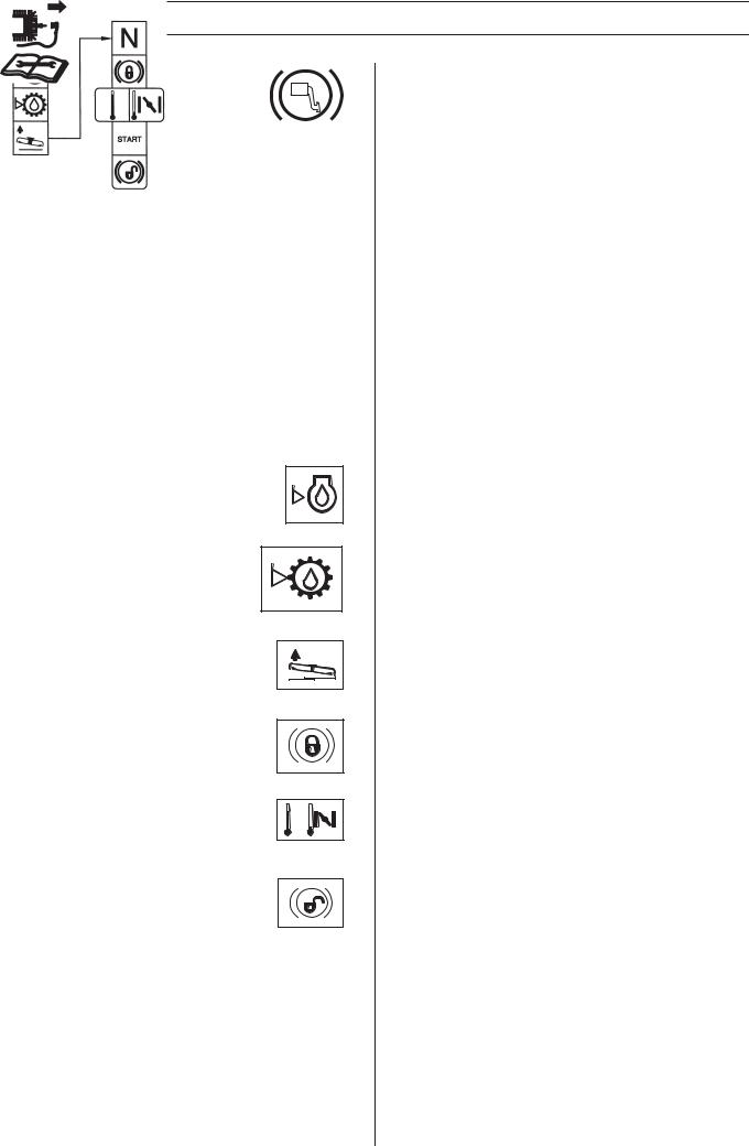
These symbols are on the machine and in the instructions.
WARNING! Careless or incorrect use can result in serious or fatal injury to the operator or others.
Please read the operator’s manual carefully and make sure you understand the instructions before using the machine.
Always wear:
•Approved hearing protection
This product is in accordance with applicable EC directives.
Neutral
Fast
Slow
Stop the engine.
Choke
Fuel
Oil level
Cutting height
Backwards
Forwards
6 – English
Ignition
Hydrostatic freewheel
Parking brake
Noise emission to the environment according to the European Community’s Directive. The machine’s emission is specified in chapter Technical data and on label.
Clutch in
Clutch out
Rotary blades Keep hands and feet away from under the hood when the engine is running
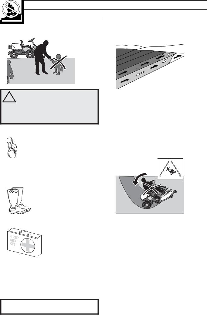
Risk that the machine will tip over
Never drive across a slope
Never use the machine if persons, especially children, or animals, are in the vicinity
Never carry passengers on the machine or equipment
Drive very slowly if no cutting unit is fitted
KEY TO SYMBOLS
Brake
Starting instructions
Switch off the engine and take off the ignition cable before repairs or maintenance
Check the engine’s oil level
Check transmission oil level
Lift up the cutting unit
Apply the parking brake.
If the engine is cold, use the choke
Release the parking brake before driving
English – 7

SAFETY INSTRUCTIONS
Safety instructions
These instructions are for your safety. Read them carefully.
Insure your Rider
•Check the insurance coverage for your new Rider.
•Contact your insurance company.
•You should have fully comprehensive insurance including: third party, fire, damage, theft and liability
General use
•Read all the instructions in this operator’s manual and on the machine before you start it. Ensure you understand them and then observe them.
WARNING! The ignition system of this
!machine produces an electromagnetic field during operation. This field may under some circumstances interfere with pacemakers.To reduce the risk of serious or fatal injury, we recommend persons with pacemakers to consult their physician and the pacemaker manufacturer before operating this machine.
•Learn how to use the machine and its controls safely and learn to how to stop quickly. Also learn to recognize the safety decals.
•Only allow the machine to be used by adults who are familiar with its use.
•Make sure nobody else is in the vicinity of the machine when you start the engine, engage the drive or drive off.
•Clear the area of objects such as stones, toys, wires, etc. that may become caught in the blades and be thrown out.
•Stop the engine and prevent the engine from being started until you have cleaned the outlet channel.
•Look out for the ejector and do not direct it towards anyone.
•Stop the engine and prevent it from starting before you clean the cutting unit.
•Remember that the driver is responsible for dangers or accidents.
•Never carry passengers. The machine is only intended to be used by one person.
•Always look downwards and backwards before and while reversing. Keep watch for both large and small obstacles.
•Slow before cornering.
•Switch off the blades when you are not mowing.
•Take care when rounding a fixed object, so that the blades do not hit it. Never run the machine over foreign objects.
WARNING! This machine can sever hands
!and feet as well as throw objects. Failure to observe the safety instructions can result in serious injuries.
WARNING! Engine exhaust, some of its
!constituents and certain vehicle components contain or emit chemicals considered to cause cancer, birth defects or other reproductive impairment. The engine emits carbon monoxide, which is a colourless, poisonous gas. Do not use the machine in enclosed spaces.
•Only use the machine in daylight or in other well-lit conditions. Keep the machine at a safe distance from holes or other irregularities in the ground. Pay attention to other possible risks.
•Never use the machine if you are tired, if you have consumed alcohol, or if you are taking other drugs or medication that can affect your vision, judgement or coordination.
•Keep an eye on the traffic when working close to a road or when crossing it.
•Never leave the machine unsupervised with the engine running. Always stop the blades, apply the parking brake, stop the engine and remove the keys before leaving the machine.
8 – English
SAFETY INSTRUCTIONS
•Never allow children or other persons not trained in the use of the machine to use or service it. Local laws may regulate the age of the user.
WARNING! You must use approved personal
!protective equipment whenever you use the machine. Personal protective equipment cannot eliminate the risk of injury but it will reduce the degree of injury if an accident does happen. Ask your dealer for help in choosing the right equipment.
•Use hearing protection to minimise the risk of hearing impairment.
•Never wear loose fitting clothes that can catch in moving parts.
•Never use the machine when barefoot. Always wear protective shoes or protective boots, preferably with steel toes.
•Make sure that you have first aid equipment close at hand when using the machine.
Driving on slopes
Driving on slopes is one of the operations where the risk of the driver losing control of the machine or of it overturning is the greatest; this can result in serious injury or death. All slopes demand extra care. If you cannot reverse up a slope or if you feel unsure, do not mow it.
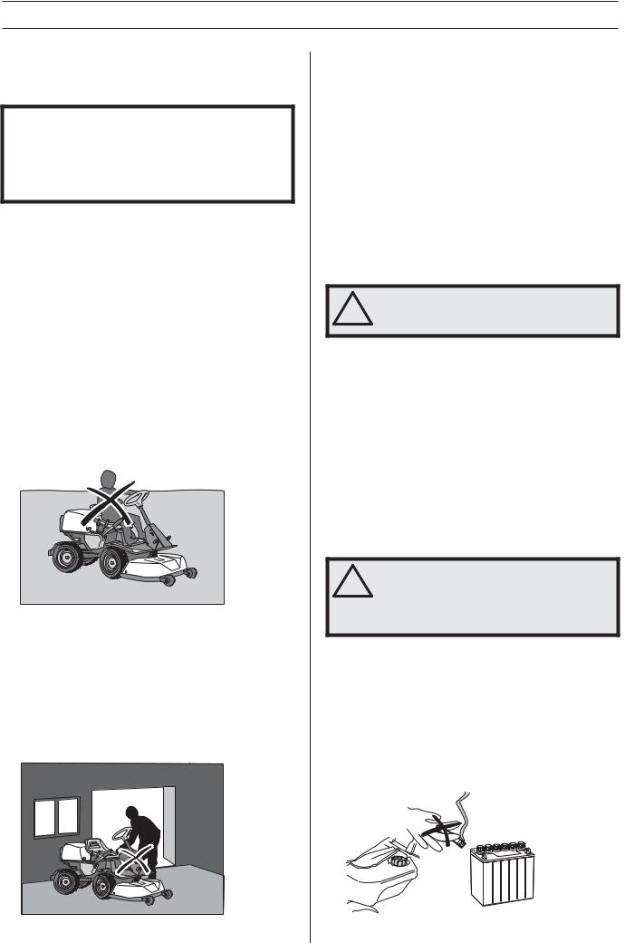
IMPORTANT INFORMATION
Do not drive down slopes with the unit raised.
This is what you do
•Remove obstacles such as stones, branches, etc.
•Mow upwards and downwards, not sideways.
•Do not use the machine on ground that slopes more than 10°.
•Avoid starting or stopping on a slope. If the tyres start to slip, stop the blades and drive slowly down the slope.
•Always drive smoothly and slowly on slopes.
•Do not make any sudden changes in speed or direction.
•Avoid unnecessary turns on slopes, if necessary, turn slowly and gradually downwards if possible. Drive slowly. Do not turn the wheel sharply.
•Watch out for and avoid driving over furrows, holes and bumps. It is easier for the machine to overturn on uneven ground. Tall grass can hide obstacles.
•Take extra care if any attachments are fitted that can change the stability of the machine.
•Do not mow too close to edges, ditches or banks. The machine can suddenly overturn if one wheel comes over the edge of a steep slope or a ditch, or if an edge gives way.
•Do not mow wet grass. It is slippery, and tyres can lose their grip so that the machine skids.
•Do not try to stabilize the machine by putting your foot on the ground.
•When cleaning the chassis, the machine may never be driven near verges or ditches.
English – 9
SAFETY INSTRUCTIONS
•Follow the manufacturer’s recommendations regarding wheel weights or counterbalance weights to increase machine stability.
IMPORTANT INFORMATION
Wheel weights fitted on the rear wheels are recommended when driving on slopes for safer steering and improved manoeuvrability. Consult your dealer concerning the use of wheel weights if you are unsure. Wheel weights can not be used on AWD-machines. Use counterweights.
Children
•Serious accidents may occur if you fail to be on your guard for children in the vicinity of the machine. Children are often attracted to the machine and mowing. Never assume that children will remain where you last saw them.
•Keep children away from the area to be mowed and under close supervision by another adult.
•Keep an eye out and shut off the machine if children enter the work area.
•Before and during reversing procedures, look behind you and down for small children.
•Never allow children to ride along. They can fall off and seriously injure themselves or be in the way for safe manoeuvring of the machine.
•Never allow children to operate the machine.
•Be particularly careful near corners, bushes, trees or other objects that block your view.
Maintenance
•Stop the engine. Prevent starting by removing the ignition cable from the spark plug or remove the ignition key before making any adjustments or carrying out maintenance.
•Never fill the fuel tank indoors.
•Petrol and petrol fumes are poisonous and extremely flammable. Be especially careful when handling petrol, as carelessness can result in personal injury or fire.
•Only store fuel in containers approved for the purpose.
•Never remove the fuel cap and fill the petrol tank while the engine is running.
•Allow the engine to cool before refuelling. Do not smoke. Do not fill petrol in the vicinity of sparks or naked flames.
•Handle oil, oil filters, fuel and the battery carefully, of environmental considerations. Follow the local recycling requirements.
•Electrical shocks can cause injuries. Do not touch cables when the engine is running. Do not test the ignition system with your fingers.
WARNING! The engine and the exhaust
!system become very hot during operation. Risk of burn injuries if touched.
•If leaks arise in the fuel system, the engine must not be started until the problem has been resolved.
•Store the machine and fuel in such a way that there is no risk that leaking fuel or fumes can cause any damage.
•Check the fuel level before each use and leave space for the fuel to expand, because the heat from the engine and the sun may otherwise cause the fuel to expand and overflow.
•Avoid overfilling. If you spill petrol on the machine, wipe up the spill and wait until it has evaporated before starting the engine. If you spill on your clothing, change your clothing.
•Allow the machine to cool before performing any actions in the engine compartment.
WARNING! The battery contains lead and
!lead pollutants, chemicals that are considered to cause cancer, birth defects or other reproductive impairment. Wash your hands after touching the battery.
•Be especially careful when handling battery acid. Acid on the skin can cause serious corrosive injuries. In the event of spillage on the skin wash immediately with water.
•Acid in the eyes can cause blindness, contact a doctor immediately.
•Take care with battery maintenance. Explosive gases form in the battery. Never perform maintenance on the battery while smoking or in the vicinity of open flames or sparks. This can cause the battery to explode and cause serious injuries.
10 – English
SAFETY INSTRUCTIONS
•Make sure all nuts and bolts are tightened correctly and that the equipment is in good condition.
•Do not modify safety equipment. Check regularly to be sure it works properly. The machine must not be driven if protective plates, protective covers, safety switches or other protective devices are not fitted or are defective.
•Observe the risk of injury caused by moving or hot parts if the engine is started with the engine cover open or protective cowlings removed.
•Do not change the setting of governors and avoid running the engine at excessively high revs. If you run too fast, you risk damaging the machine components.
•Never use the machine indoors or in spaces lacking proper ventilation. Exhaust fumes contain carbon monoxide, an odourless, poisonous and highly dangerous gas.
•Stop and inspect the equipment if you run over or into anything. If necessary, make repairs before starting.
•Never make adjustments with the engine running.
•The machine is tested and approved only with the equipment originally provided or recommended by the manufacturer.
•The blades are sharp and can cause cuts. Wrap the blades or wear protective gloves when handling them.
•Check regularly that the parking brake works. Adjust and maintain as required.
•The mulching unit should only be used where better quality mowing is required and in known areas.
•Reduce the risk of fire by removing grass, leaves and other debris that may have fastened on the machine. Allow the machine to cool before putting it in storage.
Transport
IMPORTANT INFORMATION
The parking brake is not sufficient to lock the machine during transport. Ensure you secure the machine firmly to the transporting vehicle.
•The machine is heavy and can cause serious crush injuries. Take extra care when loading it onto or off a vehicle or trailer.
•Use an approved trailer to transport the machine. Activate the parking brake, and secure the machine using approved fasteners, such as tension belts, chains or ropes when transporting.
•Check and observe local road traffic regulations before transporting or driving the machine on roads.
English – 11

WHAT IS WHAT?
|
|
PF 21 |
8 |
10 |
4 |
3 |
|
|
|
PF 21 AWD |
|
|
|
5 |
|
|
|
|
|
|
|
|
|
|
|
|
|
|
|
2 |
|
|
|
|
9 |
7 |
6 |
1 |
|
|
|
PR 17, PR 17 AWD |
|
|
|||
12 |
11 |
10 9 8 7 6 5 4 3 |
2 1 |
|
|||
13 |
14 |
15 |
16 |
|
17 |
18 |
19 |
Location of the controls
1 |
Switch for the power outlet |
11 |
Speed limiter for reversing |
2 |
Power outlet |
12 |
Speed limiter for driving forward |
3 |
Throttle control |
13 |
Parking brake |
4 |
Switch for the lights |
14 |
Lock button for parking brake |
5 |
Ignition lock |
15 |
Seat adjustment. |
6 |
Choke control |
16 |
Lever to disengage the driving front axle, PR 17 AWD and |
7 |
Lever for hydraulic lift of attachments |
|
PF 21 AWD |
|
|
||
8 |
Cutting height adjustment lever |
17 |
Fuel cap |
|
|
||
9 |
Mechanical Lifting Lever for Cutting Unit |
18 |
Cover lock |
|
|
||
10 |
Counter |
19 |
Lever to disengage the drive, PR 17 and PF 21 |
|
Lever to disengage the driving rear axle, PR 17 AWD and |
||
|
|
|
PF 21 AWD
12 – English
PRESENTATION
Presentation
Congratulations on your choice of an excellent quality product that will give you great pleasure for many years. This operator’s manual describes PR 17, PR 17 AWD, PF 21 and PF 21 AWD. The machines are equipped with a four-stroke V- Twin engine from Kawasaki.
The machines are equipped with power steering and hydraulic lifts. PR 17 AWD and PF 21 AWD also have all wheel drive.
The power transmission from the engine is handled by a hydrostatic gearbox, which allows variable variation of the speed by using the pedals. One pedal for driving forward and one for reverse.
Throttle control
The throttle control regulates the engine speed, and thereby also the rotation speed of the blades.
To increase or reduce the engine speed the control is moved forwards or backwards.
Avoid idling the engine for long periods, as there is a risk of carbon build-up on the spark plugs.
Choke control
The choke lever is used for cold starting and to give the engine a richer fuel mixture.
For cold starting the lever is moved backwards to its end position.
Speed limiter
The speed of the machine is steplessly regulated with two pedals. Pedal (1) is used to drive forwards, and pedal (2) to drive backwards.
1
2
WARNING! Make sure that branches do not
!obstruct the pedals when mowing under bushes. Otherwise there is a risk you may lose control.
Counter
The chronometer shows how many hours the engine has been running.
Any time when the engine is not running but the ignition is switched on is not registered.The last digit shows tenths of an hour (6 minutes).
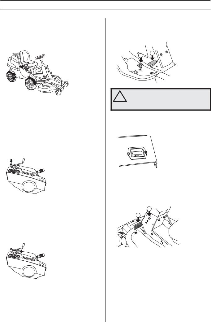
Parking brake
The parking brake is applied as follows:
2
1
1Press down the parking brake pedal (1).
2Press in the lock button (2) on the steering column.
3Release the parking brake pedal while keeping the button pressed in.
The parking brake lock disengages automatically when the brake pedal is pressed.
English – 13
PRESENTATION
Cutting unit
PR 17 and PR 17 AWD can be equipped with three different cutting units. CombiTurf 94, CombiTurf 103 and CombiTurf 112
PF 21 and PF 21 AWD can be equipped with two different cutting units. CombiTurf 112 and CombiTurf 122
The Combi-unit, equipped with a BioClip-plug, finely chops the cuttings to fertiliser. Without the BioClip-plug the unit works in the same way as a rear ejection unit.The rear ejector ejects the clippings behind the unit without finely chopping them.
Lever for hydraulic lift of attachments
The lifting lever is used to put the cutting unit in either the transport or mowing position when hydraulic pressure is available.
When the lever is moved to the transport position, the blade brake is automatically activated so that the blades stop within about 5 seconds.
Lifting the Cutting Unit (Transport
Position)
Pull the lever backwards to engage the transport position.The cutting unit will lift up and the blades stop rotating.
Secure the cutting unit if necessary using the mechanical lifting lever.
Lowering the Unit (Mowing Position)
If the cutting unit is secured in the transport position using the mechanical lifting lever, move the mechanical lifting lever to the cutting position.
Move the hydraulic lifting lever forwards to engage the cutting position. The unit is lowered and the blades begin to rotate.
In order to ensure that the hydraulic cylinder is in the outer position, hold the lever in the forward position for a half to one second.
Mechanical Lifting Lever for Cutting Unit
The lever is used as a backup lever to put the cutting unit in either the transport or mowing position when hydraulic pressure is unavailable. It can also be used to mechanically secure the cutting unit in the transport position.
The lever must be used when starting the engine, if the engine stopped with the unit in the mowing position, in order to raise the unit so that the start lock circuit is disengaged.
When the lever is moved to the transport position, the blade brake is automatically activated so that the blades stop within about 5 seconds.
Transport position
If the lever is pulled backwards the unit is raised and the blades automatically stop rotating (transport position).
14 – English
PRESENTATION
Mowing Position
If the lock button is pressed in and the lever is moved forwards the unit will be lowered and the blades will automatically start to rotate (mowing position).
If this does not happen it is probably because the unit has been lifted with the hydraulic lifting lever. Lower the unit to the mowing position with the lever for the hydraulic lift.
Cutting height adjustment lever
The cutting height can be adjusted to 7 different positions with the cutting height lever.
It is important that the air pressure in both front wheels is equal, 60 kPa/8.5 PSI, to produce an even cutting height.
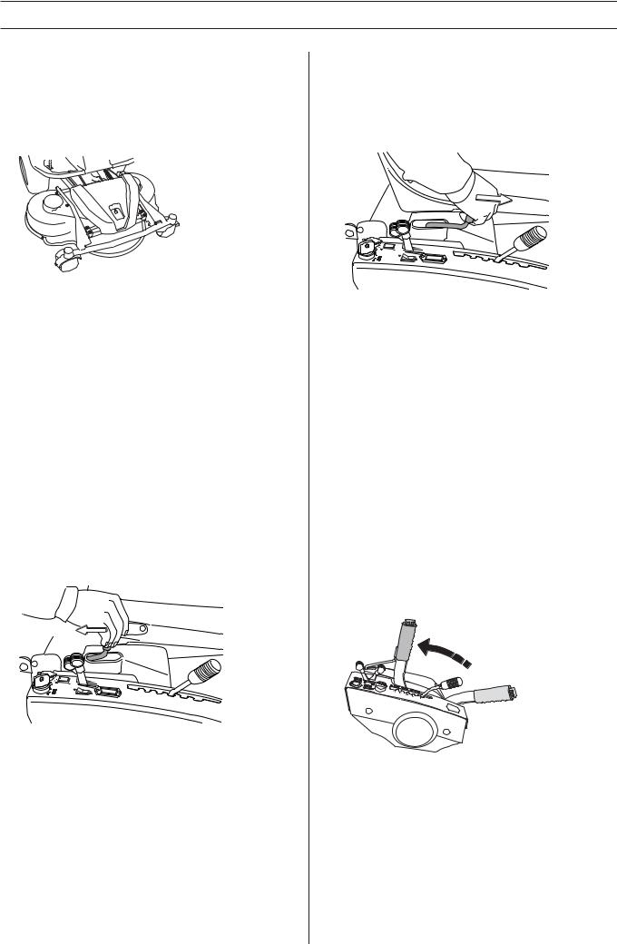
Seat
The seat has a jointed attachment on the front edge and can be tipped forward.
The seat can also be adjusted lengthways.
To adjust move the lever under the front edge of the seat to the left, so that the seat can be moved forward or backwards to the required position.
2
1
The seat springing can be adjusted by moving the rubber stops in their mountings on the underside of the seat. Place both stops in the front, middle or rear.
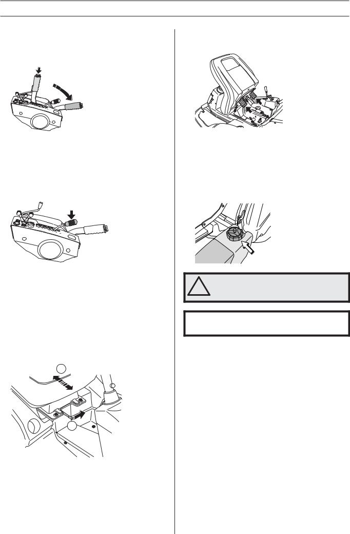
Fuelling
The engine runs on unleaded petrol with a minimum octane rating of 87 (not mixed with oil). We recommend the use of biodegradable alkylate petrol. (max. methanol 5%, max. ethanol 10%, max. MTBE 15%)
Do not fill the tank completely, leave an expansion area of at least 2.5 cm (1“).
WARNING! Petrol is highly inflammable.
!Exercise care and refuel outdoors (see safety instructions).
IMPORTANT!
Do not use the fuel tank as a support area.
English – 15
PRESENTATION
Lights and power outlet
PR 17 and PR 17 AWD
2 3
 1
1

PF 21 and PF 21 AWD
 2 3
2 3
1
The lights are switched on and off using the power switch (1) on the control panel.
A seat heater or mobile phone charger are examples of articles that can be connected to the power socket (2).
The power outlet is switched on and off using power switch (3) on the control panel.
The voltage is 12 V.
The power outlet is fuse protected by its own fuse, which is located below the ignition switch.
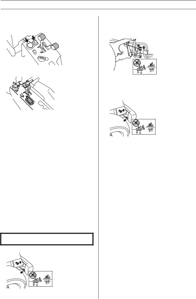
Release lever
The release control must be pulled out in order for the machine to be moved when the engine is shutoff.
Should you attempt to drive the machine with the clutch controls pulled out it will not move. The drive on the axle is disengaged when one of the controls is pulled out.
Pull the controls to the end positions, do not use an intermediate position.
Clutch control PR 17 AWD and PF 21 AWD
PR 17 AWD and PF 21 AWD have one control for the front axle and one control for the rear axle.
IMPORTANT! Always drive the machine with both clutch controls pressed in.
•Clutch control, rear axle
- Control drawn out, drive system disengaged.
-Control depressed, drive system engaged.
•Clutch control, front axle
The control is positioned on the inside of the left front wheel.
-Rear control (pulled out), drive system disengaged.
-Front control (pushed in), drive system engaged.
Clutch control PR 17 and PF 21
•Pull out the control to disengage the drive system.
•Push in the control to engage to the drive system.
16 – English
Loading...