


Z440
Table of contents
 Loading...
HP Z440, Z640, and Z840 Workstation
Series
Maintenance and Service Guide

Copyright Information
Warranty
Trademark Credits
© Copyright 2014, 2016 HP Development
Company, L.P.
Third Edition: November 2016
First Edition: October 2014
Part Number: 748721-004
The information contained herein is subject to
change without notice. The only warranties for
HP products and services are set forth in the
express warranty statements accompanying
such products and services. Nothing herein
should be construed as constituting an
additional warranty. HP shall not be liable for
technical or editorial errors or omissions
contained herein.
Windows 8: Not all features are available in all
editions of Windows 8. This workstation may
require upgraded and/or separately purchased
hardware, drivers, and/or software to take full
advantage of Windows 8 functionality. Go to
http://www.microsoft.com for details.
Windows 7: This workstation may require
upgraded and/or separately purchased
hardware and/or a DVD drive to install the
Windows 7 software and take full advantage of
Windows 7 functionality. Go to
http://www.microsoft.com for details.
Microsoft and Windows are U.S. registered
trademarks of the Microsoft group of
companies.
Intel, Intel Xeon, and Thunderbolt are
trademarks of Intel Corporation in the U.S. and
other countries.
Bluetooth is a trademark owned by its
proprietor and used by Hewlett-Packard
Company under license.
ENERGY STAR is a registered trademark owned
by the U.S. Environmental Protection Agency
(EPA).
Red Hat is a registered trademark of Red Hat,
Inc. in the United States and other countries.

About this guide
This guide provides service and maintenance information, technical details and conguration guidance for the
HP Z440, Z640, and Z840 Workstations.
IMPORTANT: Removal and replacement procedures are now available in videos on the HP website.
Go to the HP Customer Self-Repair Services Media Library at http://www.hp.com/go/sml.
Hardware overview on page 1
System management on page 23
Component replacement information and guidelines on page 45
Diagnostics and troubleshooting on page 76
Conguring password security and resetting CMOS on page 99
Linux technical notes on page 103
Conguring RAID devices on page 106
System board designators on page 116
Guide topics
NOTE: View the HP Z440, Z640, and Z840 Workstation Series User Guide at http://www.hp.com/support/
workstation_manuals.
iii

iv About this guide

Table of contents
1 Hardware overview ........................................................................................................................................ 1
HP Z440 Workstation components ....................................................................................................................... 1
HP Z440 Workstation front panel components .................................................................................. 2
HP Z440 Workstation rear panel components .................................................................................... 3
HP Z440 Workstation chassis components ........................................................................................ 4
HP Z440 Workstation system board components .............................................................................. 5
HP Z440 Workstation system board architecture .............................................................................. 6
HP Z440 Workstation specications ................................................................................................... 6
HP Z640 Workstation components ....................................................................................................................... 8
HP Z640 Workstation front panel components .................................................................................. 8
HP Z640 Workstation rear panel components .................................................................................... 9
HP Z640 Workstation chassis components ...................................................................................... 10
HP Z640 Workstation system board components ............................................................................ 11
HP Z640 Workstation system board architecture ............................................................................ 12
HP Z640 Workstation system board riser architecture .................................................................... 13
HP Z640 Workstation specications ................................................................................................. 13
HP Z840 Workstation components ..................................................................................................................... 15
HP Z840 Workstation front panel components ................................................................................ 15
HP Z840 Workstation rear panel components ................................................................................. 16
HP Z840 Workstation chassis components ...................................................................................... 17
HP Z840 Workstation system board components ............................................................................ 18
HP Z840 Workstation system board architecture ............................................................................ 19
HP Z840 Workstation specications ................................................................................................. 20
Environmental specications .............................................................................................................................. 21
Ensuring proper ventilation ................................................................................................................................. 22
2 System management ................................................................................................................................... 23
Power management features .............................................................................................................................. 23
ERP compliance mode ....................................................................................................................... 23
Hyper-Threading Technology (HTT) .................................................................................................. 24
SATA Power Management ................................................................................................................. 24
Intel Turbo Boost Technology ........................................................................................................... 24
BIOS ROM ............................................................................................................................................................. 24
Computer Setup (F10) Utility ............................................................................................................................... 25
Computer Setup (F10) Utility functions ............................................................................................ 25
Accessing Computer Setup (F10) Utility ........................................................................................... 26
v

Computer Setup (F10) Utility menu .................................................................................................. 27
Desktop management ......................................................................................................................................... 32
Initial computer conguration and deployment ............................................................................... 33
Installing a remote system ............................................................................................................... 33
Copying a setup conguration to another computer ....................................................................... 33
Updating and managing software .................................................................................................... 34
LANDesk Software ............................................................................................................................. 34
HP Driver Pack ................................................................................................................................... 34
HP SoftPaq Download Manager ........................................................................................................ 34
HP System Software Manager .......................................................................................................... 35
ROM Flash .......................................................................................................................................... 35
Remote ROM Flash .......................................................................................................... 35
HPQFlash ......................................................................................................................... 35
FailSafe Boot Block ............................................................................................................................ 35
Recovering the computer from Boot Block Recovery mode .......................................... 36
Workstation security ......................................................................................................................... 36
Asset tracking ................................................................................................................. 36
SATA hard drive security ................................................................................................. 37
DriveLock applications ................................................................................. 37
Using DriveLock ............................................................................................ 38
Password security ........................................................................................................... 39
Establishing a setup password using Computer Setup (F10) Utility ........... 39
Establishing a power-on password using computer setup ......................... 39
Entering a power-on password .................................................................... 40
Entering a setup password ........................................................................... 40
Changing a power-on or setup password .................................................... 40
Deleting a power-on or setup password ...................................................... 41
National keyboard delimiter characters ...................................................... 42
Clearing passwords ...................................................................................... 42
Chassis security .............................................................................................................. 42
Smart Cover Sensor ...................................................................................... 42
Cable lock (optional) ..................................................................................... 43
Fault notication and recovery ......................................................................................................... 43
ECC fault prediction ......................................................................................................... 43
Thermal sensors ............................................................................................................. 43
Dual-state power button ................................................................................................................... 43
Changing the power button conguration (Windows only) ........................................... 44
3 Component replacement information and guidelines ...................................................................................... 45
Warnings and cautions ........................................................................................................................................ 45
Service considerations ......................................................................................................................................... 46
vi

Tools and software requirements ..................................................................................................... 46
Electrostatic discharge (ESD) information ........................................................................................ 46
Product recycling ................................................................................................................................................. 48
Component replacement guidelines ................................................................................................................... 48
Battery ............................................................................................................................................... 48
Cable management ........................................................................................................................... 49
Processor and processor heatsink .................................................................................................... 50
Expansion slots ................................................................................................................................. 51
Card conguration restrictions for power supplies ........................................................ 51
Choosing an expansion card slot .................................................................................... 51
HP Z440 Workstation slot identication and description .............................................. 52
HP Z440 Workstation installation sequence recommendations ................................... 53
HP Z640 Workstation slot identication and description .............................................. 54
HP Z640 Workstation installation sequence recommendations ................................... 54
HP Z840 Workstation slot identication and description .............................................. 56
HP Z840 Workstation installation sequence recommendations ................................... 57
Hard drives and optical drives ........................................................................................................... 59
Handling hard drives ....................................................................................................... 59
Removal and replacement tips ....................................................................................... 59
Drive installation and cabling scenarios ......................................................................... 59
HP Z440 Workstations — Intel AHCI SATA controller guidelines ................. 60
HP Z440 Workstations — LSI 9217-4i4e RAID controller guidelines .......... 61
HP Z640 Workstations — Intel AHCI SATA controller guidelines ................. 62
HP Z640 Workstations — LSI 9217-4i4e RAID controller guidelines .......... 63
HP Z840 Workstation cabling guidelines ..................................................... 64
Memory .............................................................................................................................................. 65
Supported DIMM congurations ..................................................................................... 65
BIOS errors and warnings ............................................................................................... 65
DIMM installation guidelines .......................................................................................... 65
HP Z440 Workstation DIMM installation order ............................................................... 66
HP Z640 Workstation DIMM installation order ............................................................... 67
HP Z840 Workstation DIMM installation order ............................................................... 68
Power supply ..................................................................................................................................... 69
Power supply specications ........................................................................................... 69
HP Z440 power supply specications .......................................................... 69
HP Z640 power supply specications .......................................................... 70
HP Z840 power supply specications .......................................................... 71
Power consumption and heat dissipation ...................................................................... 72
Resetting the power supply ............................................................................................ 72
System board .................................................................................................................................... 72
System cabling ................................................................................................................ 73
vii

HP Z440 Workstation system cabling .......................................................... 73
HP Z640 Workstation system cabling .......................................................... 74
HP Z840 Workstation system cabling .......................................................... 75
4 Diagnostics and troubleshooting .................................................................................................................. 76
Calling support ..................................................................................................................................................... 76
Locating ID labels ................................................................................................................................................ 77
Locating warranty information ........................................................................................................................... 77
Diagnosis guidelines ............................................................................................................................................ 78
Diagnosis at startup .......................................................................................................................... 78
Diagnosis during operation ............................................................................................................... 78
Troubleshooting checklist ................................................................................................................................... 78
HP troubleshooting resources and tools ............................................................................................................. 79
Online support ................................................................................................................................... 79
Troubleshooting a problem ............................................................................................ 79
Instant Support and Active Chat ..................................................................................... 79
Customer Advisories, Customer and Security Bulletins, and Customer Notices ........... 80
Product Change Notications ......................................................................................... 80
Helpful hints ...................................................................................................................................... 80
At startup ........................................................................................................................ 80
During operation ............................................................................................................. 81
Customer Self-Repair program ....................................................................................... 81
Troubleshooting scenarios and solutions ........................................................................................................... 82
Solving minor problems .................................................................................................................... 82
Solving hard drive problems ............................................................................................................. 84
Solving display problems .................................................................................................................. 85
Solving audio problems ..................................................................................................................... 87
Solving printer problems ................................................................................................................... 88
Solving power supply problems ........................................................................................................ 88
Testing power supply ...................................................................................................... 88
Diagnostic codes and errors ................................................................................................................................ 90
Diagnostic LED and audible (beep) codes ......................................................................................... 90
LED color denitions ......................................................................................................................... 92
POST error messages ........................................................................................................................ 92
5 Using HP PC Hardware Diagnostics (UEFI) ....................................................................................................... 97
Downloading HP PC Hardware Diagnostics (UEFI) to a USB device .................................................................... 97
Additional BIOS crisis recovery tool ..................................................................................................................... 98
Using Remote HP PC Hardware Diagnostics (UEFI) settings ............................................................................... 98
Customizing Remote HP PC Hardware Diagnostics (UEFI) settings ................................................. 98
viii

6 Conguring password security and resetting CMOS ........................................................................................ 99
Preparing to congure passwords ...................................................................................................................... 99
Resetting the password jumper ........................................................................................................................ 100
Clearing and resetting the CMOS ....................................................................................................................... 101
Using the CMOS button to reset CMOS ............................................................................................ 101
Using Computer Setup (F10) Utility to reset CMOS ........................................................................ 102
Appendix A Linux technical notes .................................................................................................................. 103
System RAM ....................................................................................................................................................... 103
Audio .................................................................................................................................................................. 103
Network cards .................................................................................................................................................... 104
Hyper-Threading Technology ............................................................................................................................ 104
NVIDIA Graphics Workstations .......................................................................................................................... 104
AMD Graphics Workstations .............................................................................................................................. 105
Appendix B Conguring RAID devices ............................................................................................................. 106
RAID hard drive maximum and associated storage controller options ............................................................ 106
Supported RAID congurations ......................................................................................................................... 107
Conguring Intel SATA RAID ............................................................................................................................... 108
Conguring system BIOS ................................................................................................................. 108
Conguring RAID with the Intel utility ............................................................................................ 109
Conguring RAID on an LSI 2308 or LSI 9217-4i4e controller .......................................................................... 110
RAID 0 conguration ....................................................................................................................... 110
RAID 1 conguration ....................................................................................................................... 111
RAID 1E/10 conguration ............................................................................................................... 112
Conguring RAID on an LSI 9270-8i MegaRAID controller ................................................................................ 113
RAID 0 .............................................................................................................................................. 113
Software RAID solution ..................................................................................................................................... 114
Software RAID considerations ........................................................................................................ 114
Performance considerations ........................................................................................................... 114
Conguring software RAID .............................................................................................................. 115
Appendix C System board designators ........................................................................................................... 116
HP Z440 and Z640 Workstation system board designators ............................................................................. 116
HP Z840 Workstations ....................................................................................................................................... 118
Appendix D Statement of Volatility ................................................................................................................ 121
Z440 Workstation .............................................................................................................................................. 121
Z640 Workstation .............................................................................................................................................. 121
Z840 Workstation .............................................................................................................................................. 122
ix

Index ........................................................................................................................................................... 123
x

1 Hardware overview
This chapter presents an overview of workstation hardware components.
●
HP Z440 Workstation components
●
HP Z640 Workstation components
●
HP Z840 Workstation components
●
Environmental specications
●
Ensuring proper ventilation
HP Z440 Workstation components
For complete and current information on supported accessories and components for the computer, see
http://partsurfer.hp.com.
●
HP Z440 Workstation front panel components
●
HP Z440 Workstation rear panel components
●
HP Z440 Workstation chassis components
●
HP Z440 Workstation system board components
●
HP Z440 Workstation system board architecture
●
HP Z440 Workstation specications
HP Z440 Workstation components 1

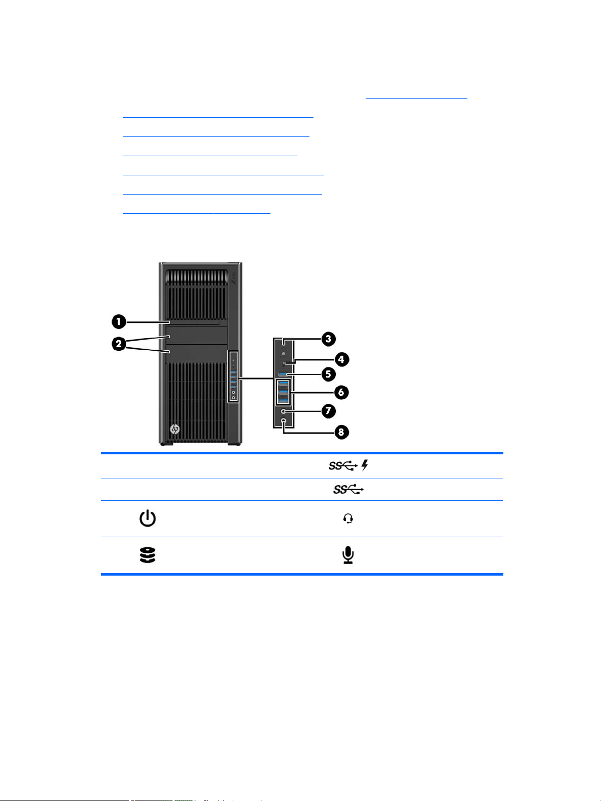
HP Z440 Workstation front panel components
1 External drive bays 5 USB 3.0 charging port
2 Optical drive 6 USB 3.0 ports (3)
3 Power button and LED 7
4 Hard drive activity light 8 Audio-in (microphone) jack
Audio-out (headphone)/Audio-in
(microphone) combo jack
2 Chapter 1 Hardware overview
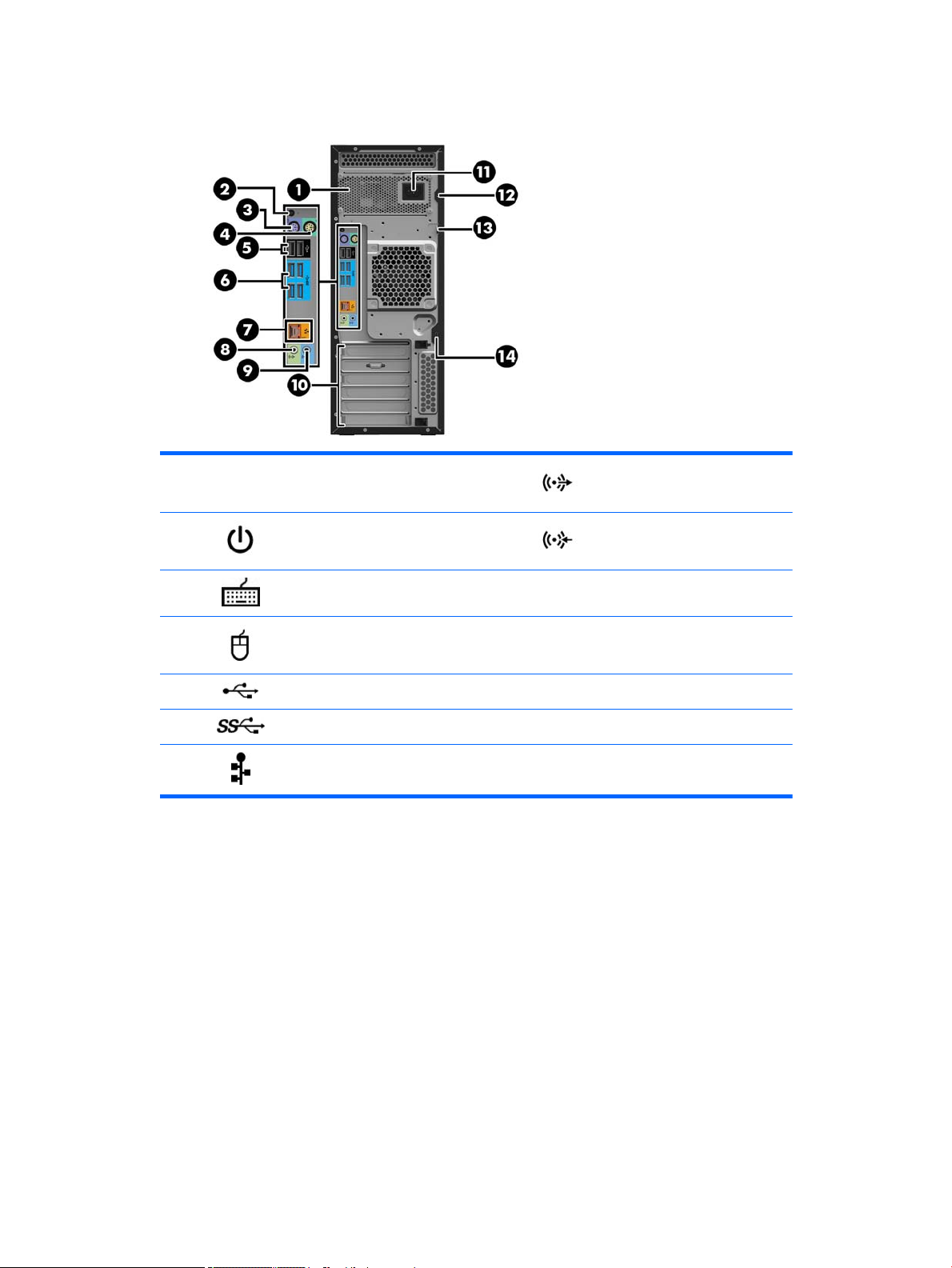
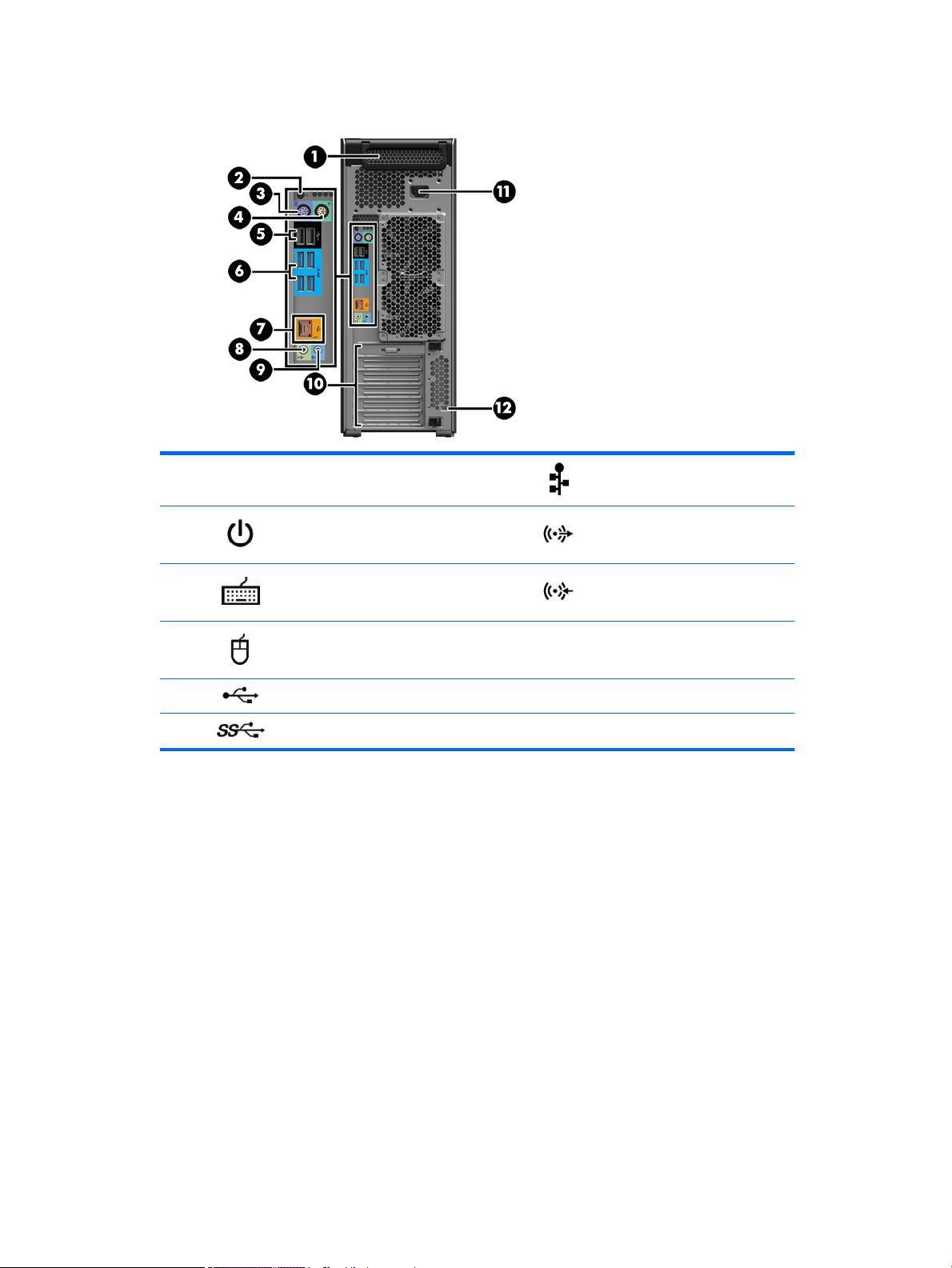
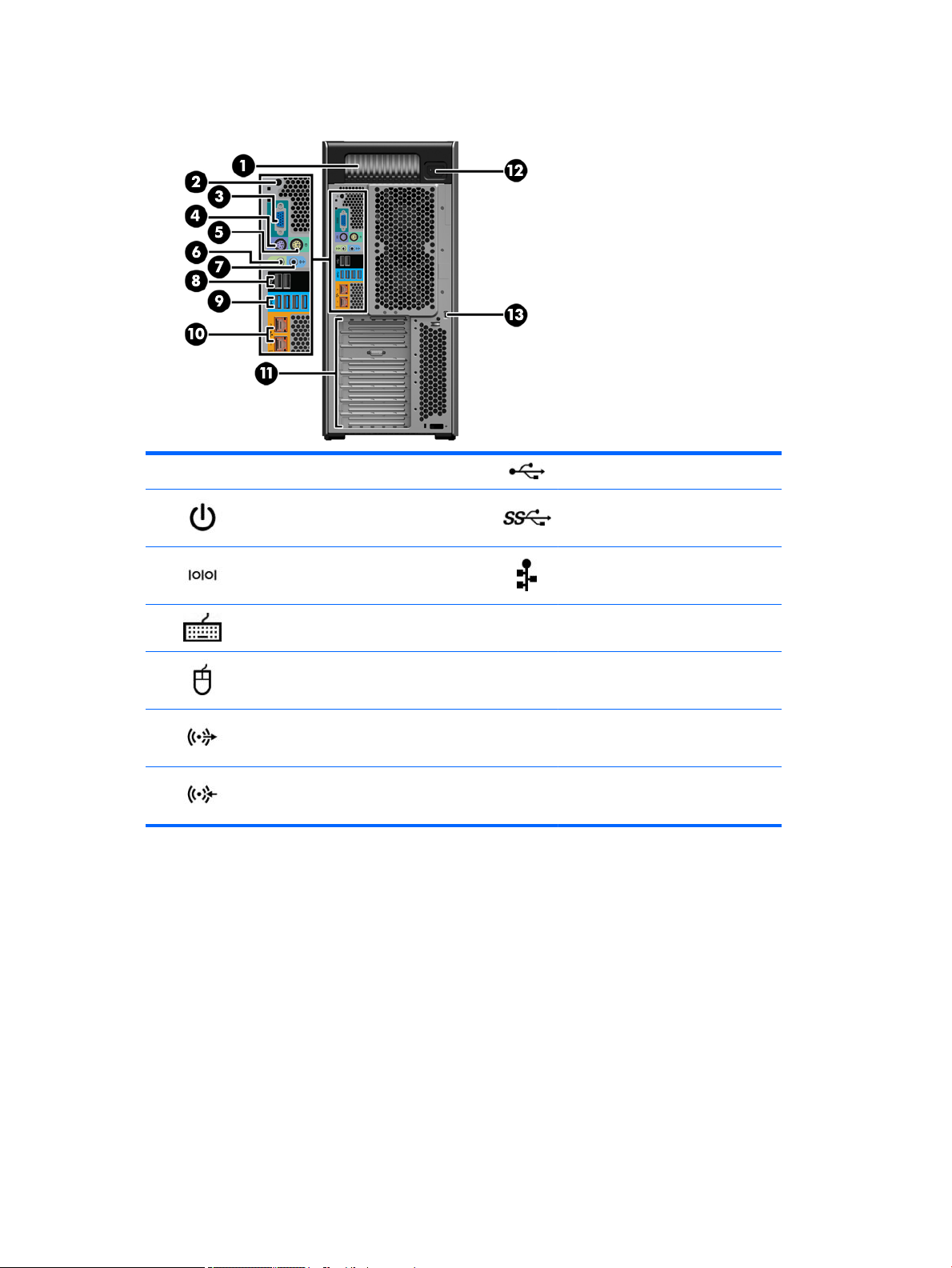
HP Z440 Workstation rear panel components
1
2 Rear power button and LED 9 Audio line-in jack (blue)
3 PS/2 keyboard connector (purple) 10 PCI/PCIe card slots
4 PS/2 mouse connector (green) 11 Power cord connector
5 USB 2.0 ports (2, black) 12 Universal chassis clamp opening
6 USB 3.0 ports (4, blue) 13 Padlock loop
7
Power supply Built-In Self-Test
(BIST) LED
AMT-enabled RJ-45 (network) jack
(orange)
8 Audio line-out jack (light green)
14
Security slot
HP Z440 Workstation components 3
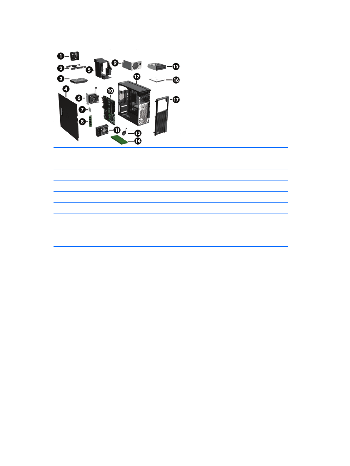
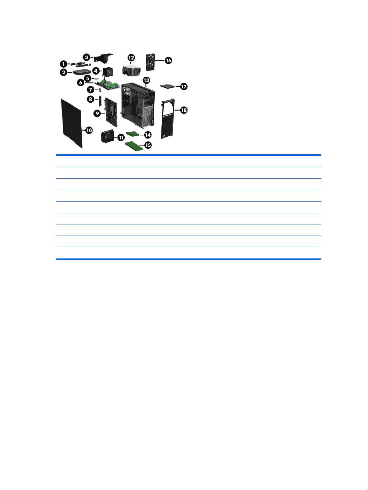
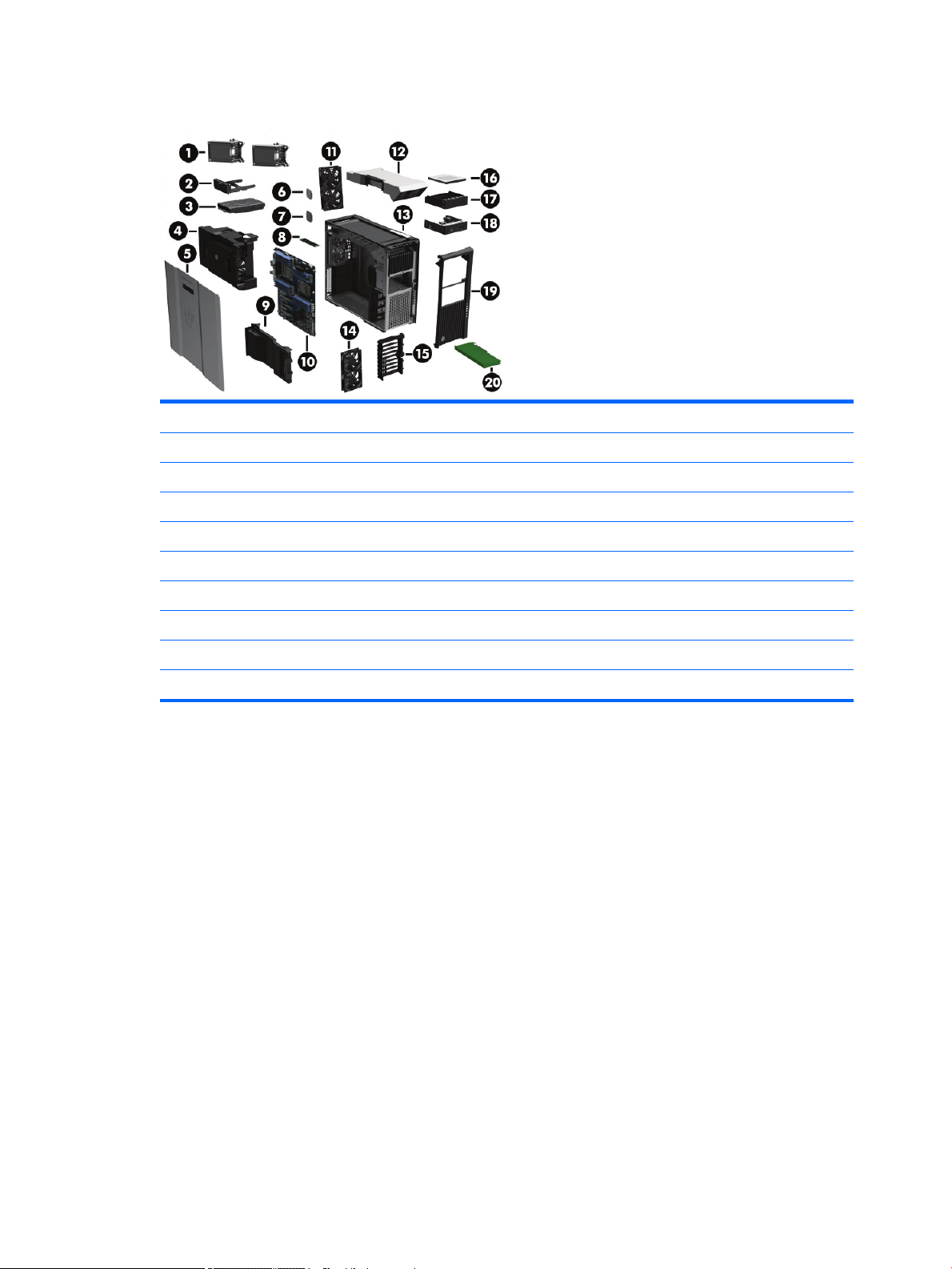
HP Z440 Workstation chassis components
1 Fan 10 System board
2 Hard drive carrier 11 Rear system fan and holder
3 Hard drive, 3.5-inch 12 Chassis
4 Side access panel 13 Speaker
5 Memory fans 14 PCIe card
6 Heat sink 15 Front bay ller (optional)
7 Processor 16 Optical drive, slim
8 Memory module (DIMM) 17 Front bezel
9 Power supply
4 Chapter 1 Hardware overview
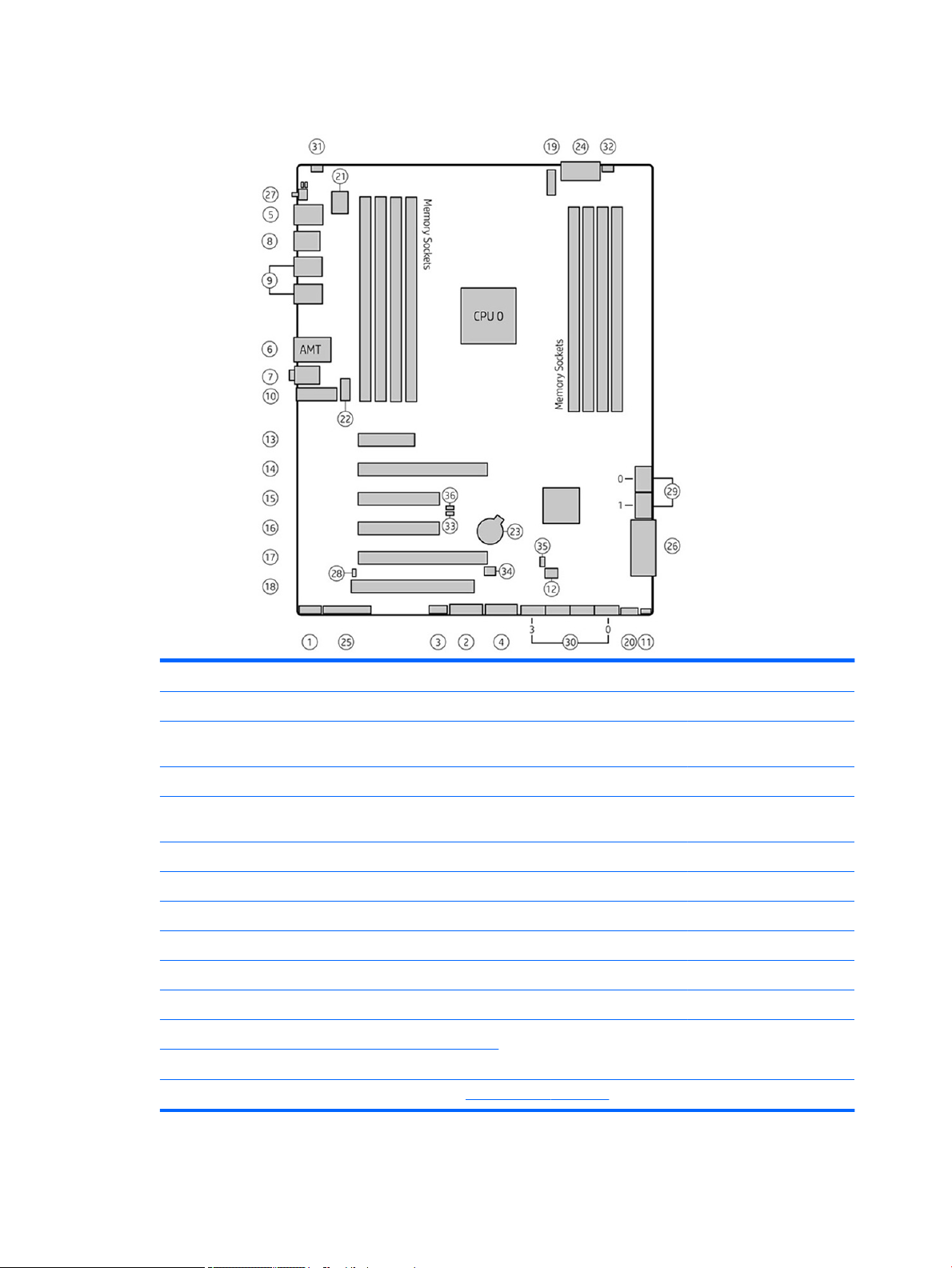
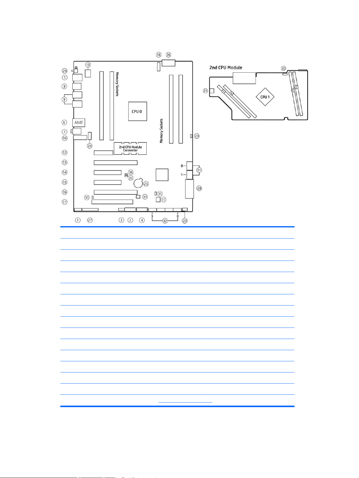
HP Z440 Workstation system board components
I/O PCI/PCIe Power Security
1 Front audio 13 PCIe2 x1 23 Battery 31 Chassis intrusion sensor
2 Front USB 3.0 14 PCIe3 x16 24 Processor and memory
power
3 Internal USB 2.0 15 PCIe2 x4 25 Front UI/power button/LED Service
4 Internal USB 3.0 16 PCIe3 x8 26 Main power 33 Boot Block Recovery (BBR)
5 Keyboard/mouse 17 PCIe3 x16 27 Rear power button/LED 34 Clear CMOS button
6 Network 18 PCI 32/33 SATA (SAS Optional) 35 ME/AMT ash override
7 Rear audio Cooling 28 Hard drive LED 36 Password jumper
8 Rear USB 2.0 19 CPU0 fan 29 SATA 6 Gb/s
9 Rear USB 3.0 20 Front fan 30 sSATA 6 Gb/s
10 Serial (optional) 21 Memory fans
11 Speaker 22 Rear fan
12
ThunderboltTM GPIO
NOTE: For related expansion card slot information, see Expansion slots on page 51
32 Chassis solenoid lock
jumper
HP Z440 Workstation components 5
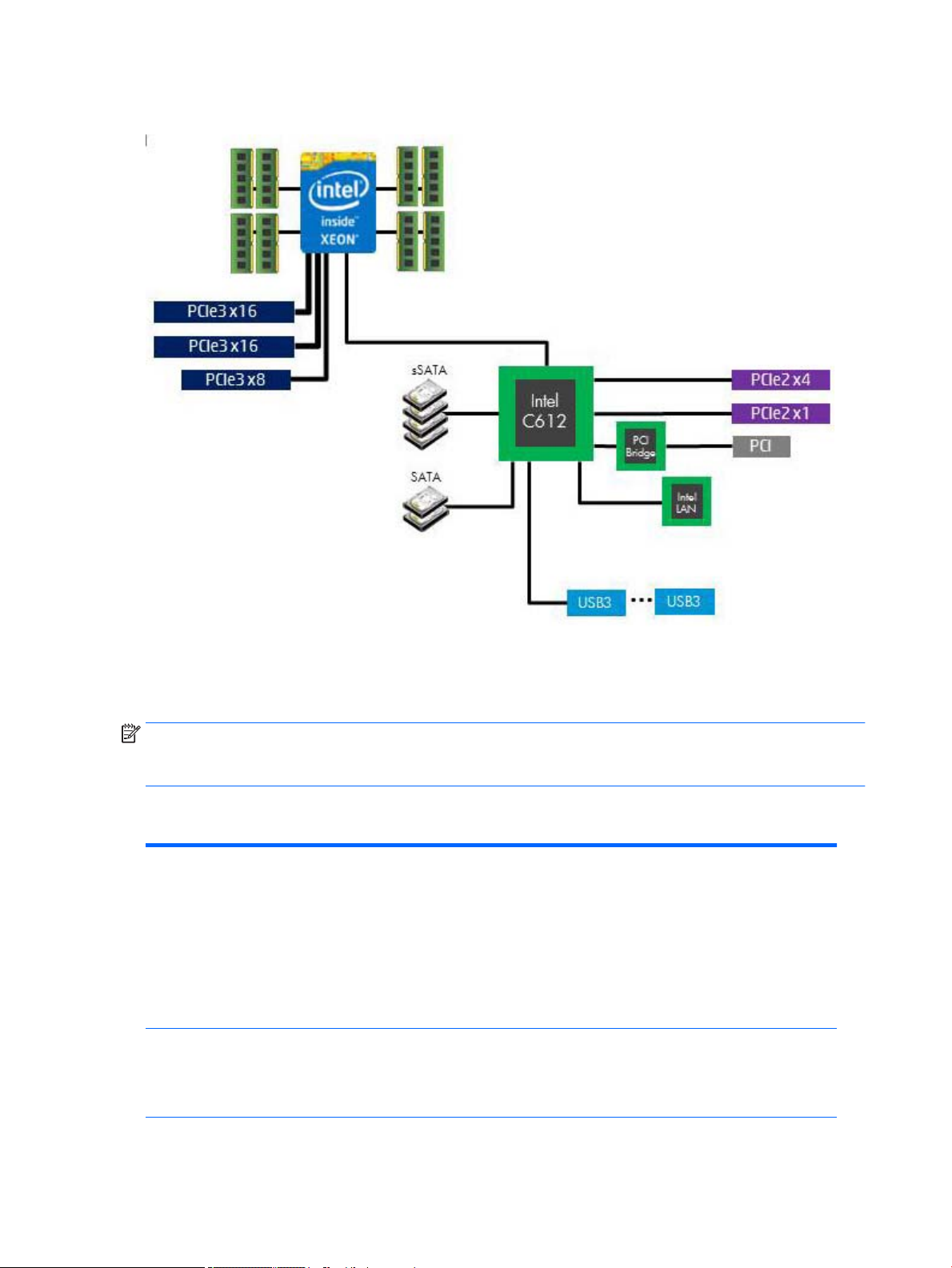
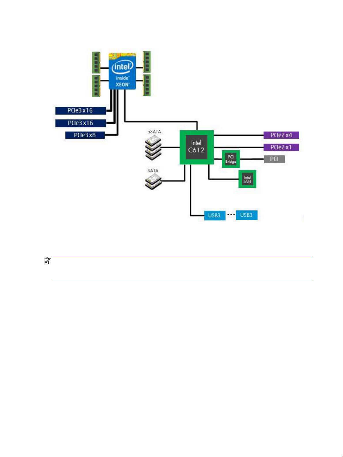
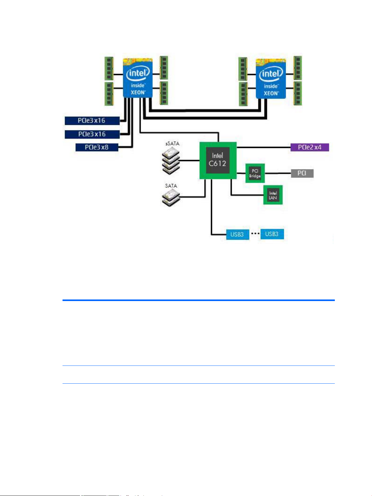
HP Z440 Workstation system board architecture
●
Dark blue slots are attached to CPU0 and available with CPU0.
●
Purple and gray slots are attached to PCH.
●
White slots are attached to CPU1 and available when CPU1 is installed.
NOTE: The PCIe designators indicate the mechanical connector size and number of electrical PCIe lanes
routed to an expansion slot. For example, x16(8) means that the expansion slot is mechanically an x16 length
connector, with 8 PCIe lanes supported.
HP Z440 Workstation specications
Intel Series C612 chipset:
●
Support for the Intel Xeon Processor E5-1600 Series and E5-2600 Series
●
Integrated 4-channel memory controller
Processor technology
Power supply
●
Microarchitecture improvements
●
Large L3 cache for superior performance
●
Intel QuickPath Interconnect (QPI) connects processors and I/O controller with speeds up to
9.6 GT/s
●
700 W Gold, 90% ecient, wide-ranging, active Power Factor Correction, two auxiliary
dongles on two 12V rails, ERP 0.5W, Built-in-Self Test (BIST)
●
525 W Bronze, 85% ecient, wide-ranging, active Power Factor Correction, ERP 0.5W,
Built-in-Self Test (BIST)
Memory technology
6 Chapter 1 Hardware overview
●
Dual in-line memory modules (DIMMs) based on DDR4 2133 MHz technology

Graphics cards
●
Error checking and correcting (ECC)-protected
●
Four direct-attach memory channels enable low-latency access and fast data transfer for
improved performance
●
Up to 128 GB system memory (16 GB DIMMs)
●
2133 MHz 4, 8, 16 GB ECC Registered DIMMs
NOTE: Only ECC DIMMs are supported.
NOTE: Distribute DIMMs across all memory channels for optimal performance.
Supports:
●
PCIe Gen3 (PCIe3) bus speeds; can support two PCIe Gen3 graphics cards in PCIe3 x16 slots
●
Up to 225 W graphics or compute card in the primary graphics slot (700 W PSU)
●
Up to 75 W graphics in primary slot (525 W PSU)
●
A second graphics card in the second PCIe3 x16 slot
●
Third and fourth 2D graphics cards in additional PCIe2 slots
●
Combined power consumption of all cards not to exceed 335 W (subject to overall system
power limitations and conguration restrictions) (700 W PSU)
●
Combined power consumption of all cards not to exceed 140 W (subject to overall system
power limitations and conguration restrictions) (525 W PSU)
NOTE: Not all graphics cards are compatible with all video transceivers and adapters. See the
graphics card documentation for specic details.
I/O technology
Weight
Chassis dimensions
●
SATA RAID 0/1/5/10 on sSATA
●
Six SATA/AHCI ports (2 SATA 6 Gb/s, 4 sSATA 6Gb/s)
●
Two ports capable of optional eSATA. eSATA capable with optional dual eSATA bulkhead kit.
●
Eight external USB 3.0 ports (4 front, 4 rear)
●
Two external USB 2.0 ports (2 rear)
●
Two internal USB 2.0 ports
●
One internal USB 3.0 port
●
Serial Attached SCSI (SAS) drives supported with 9217-4i4e plug-in card
●
Standard conguration: 13.7 kg (30.2 lb)
●
Minimum conguration: 11.0 kg (24.3 lb)
●
Maximum conguration: 17.7 kg (39.4 lb)
Tower conguration:
●
Height: 43.18 cm (17.00 in)
●
Width: 16.89 cm (6.65 in)
●
Depth: 44.45 cm (17.50 in)
Desktop conguration:
●
Height: 16.89 cm (6.65 in)
●
Width: 43.18 cm (17.00 in)
●
Depth: 44.45 cm (17.50 in)
HP Z440 Workstation components 7

HP Z640 Workstation components
For complete and current information on supported accessories and components for the computer, see
http://partsurfer.hp.com.
●
HP Z640 Workstation front panel components
●
HP Z640 Workstation rear panel components
●
HP Z640 Workstation chassis components
●
HP Z640 Workstation system board components
●
HP Z640 Workstation system board architecture
●
HP Z640 Workstation system board riser architecture
●
HP Z640 Workstation specications
HP Z640 Workstation front panel components
1 External drive bays 5 USB 3.0 charging port
2 Optical drive 6 USB 3.0 ports (3)
3 Power button and LED 7
4 Hard drive activity light 8 Microphone jack
8 Chapter 1 Hardware overview
Audio-out (headphone)/Audio-in
(microphone) combo jack
HP Z640 Workstation rear panel components
1
2 Rear power button and LED 8 Audio line-out jack (green)
3 PS/2 keyboard connector (purple) 9 Audio line-in jack (blue)
4 PS/2 mouse connector (light green) 10 PCI/PCIe card slots
5 USB 2.0 ports (2, black) 11 Power cord connector
6 USB 3.0 ports (4, blue) 12 Security slot
Power supply Built-In Self-Test
(BIST) LED
7 AMT-enabled network jack (orange)
HP Z640 Workstation components 9
HP Z640 Workstation chassis components
1 Hard drive carrier 10 Side access panel
2 Hard drive, 3.5-inch 11 Card guide and front fan
3 Fan bae 12 Power supply
4 Processor Heatsink 13 Chassis
5 Processor 14 PCI card
6 Second processor module (optional) 15 PCIe card
7 Second processor (optional) 16 Rear system fan
8 Memory module (DIMM) 17 Optical drive, slim
9 System board 18 Front bezel
10 Chapter 1 Hardware overview
HP Z640 Workstation system board components
I/O PCI/PCIe Power
1 Front audio 12 PCIe2 x1 25 Battery
2 Front USB 3.0 13 PCIe3 x16 26 Processor and memory power
3 Internal USB 2.0 14 PCIe2 x4 27 Front UI, power button, LED
4 Internal USB 3.0 15 PCIe3 x8 28 Main power
5 Keyboard/mouse 16 PCIe3 x16 29 Rear power button/LED
6 Network 17 PCI 32/33 SATA (SAS optional)
7 Rear audio Cooling 30 Hard drive LED
8 Rear USB 2.0 18 CPU0 fan 31 SATA 6 Gb/s
9 Rear USB 3.0 19 CPU0 memory fans 32 sSATA 6 Gb/s
10 Serial (option) 20 CPU1 fan (option) Service
11 Thunderbolt GPIO 21 CPU1 memory fan (option) 33 Boot Block Recovery (BBR) jumper
22 Front fan 34 Clear CMOS button
23 HDSJ 35 ME/AMT ash override
24 Rear fans 36 Password jumper
For related expansion card slot information, see Expansion slots on page 51
HP Z640 Workstation components 11
HP Z640 Workstation system board architecture
●
Dark blue slots are attached to CPU0 and available with CPU0.
●
Purple and gray slots are attached to PCH.
●
White slots are attached to CPU1 and available when CPU1 is installed.
NOTE: The PCIe designators indicate the mechanical connector size and number of electrical PCIe lanes
routed to an expansion slot. For example, x16 (8) means that the expansion slot is mechanically an x16
length connector, with 8 PCIe lanes supported.
12 Chapter 1 Hardware overview
HP Z640 Workstation system board riser architecture
●
Dark blue slots are attached to CPU0 and available with CPU0.
●
Purple and gray slots are attached to PCH.
●
White slots are attached to CPU1 and available when CPU1 is installed.
HP Z640 Workstation specications
Intel Series C612 chipset:
●
Support for the Intel Xeon Processor E5-1600 Series and E5-2600 Series
●
Processor
technology
Power supply
Memory
technology
Integrated 4-channel memory controller
●
Microarchitecture improvements
●
Large L3 cache for superior performance
●
Intel QuickPath Interconnect (QPI) connects processors and I/O controller with speeds up to 9.6 GT/s
●
925 W Gold, 90% ecient, wide-ranging, active Power Factor Correction, two auxiliary dongles on two
separate 12V rails, ERP 0.5W, Built-in-Self Test (BIST)
●
Dual in-line memory modules (DIMMs) based on DDR4 2133 MHz technology
●
Error checking and correcting (ECC)-protected
●
Eight direct-attach memory channels (four per processor) enable low-latency access and fast data
transfer for improved performance
●
Congurations with one processor have four DIMM slots; a second processor adds four more DIMM slots
●
With one processor, up to 128 GB system memory (32 GB DIMMs)
HP Z640 Workstation components 13

Graphics cards
●
With second processor, up to 256 GB system memory (32 GB DIMMs)
●
2133 MHz 4, 8, 16 ECC Registered DIMMs
●
2133 MHz 32 GB ECC Load Reducing DIMM
NOTE: Do not install memory modules into memory slots if corresponding processor is not installed.
Only Registered and LR ECC DIMMs are supported.
Do not mix any of the dierent types (RDIMM [Registered] and LR DIMM [Load Reduction]) of memory. The
system will not boot and will produce a memory error.
For maximum performance, on workstations with two processors, install the same number of DIMMs per
processor and install them in pairs of the same size.
Distribute DIMMs across all memory channels for optimal performance.
Do not install memory modules into memory slots if corresponding processor is not installed.
●
PCIe Gen3 (PCIe3) bus speeds; can support two PCIe Gen3 graphics cards in PCIe3 x16 slots
●
Up to 225 W graphics or compute card in the primary graphics slot
●
A second graphics card in the second PCIe3 x16 slot
●
Third and fourth 2D graphics cards in additional PCIe2 slots
●
Combined power consumption of all cards cannot exceed 375 W (subject to overall system power
limitations and conguration restrictions)
NOTE: Not all graphics cards are compatible with all video transceivers and adapters. See the graphics card
documentation for specic details.
I/O technology
Weight
Chassis
dimensions
●
SATA RAID 0/1/5/10 on sSATA
●
Six SATA/AHCI ports (2 SATA 6 Gb/s, 4 sSATA 6Gb/s)
●
Two ports available for optional eSATA. eSATA capable with optional dual eSATA bulkhead kit.
●
Eight external USB 3.0 ports (4 front, 4 rear)
●
Two external USB 2.0 ports (2 rear)
●
Two internal USB 2.0 ports
●
One internal USB 3.0 port
●
Serial Attached SCSI (SAS) drives supported with 9217-4i4e plug-in card
●
Standard conguration: 17.0 kg (37.5 lb)
●
Minimum conguration: 15.0 kg (33.1 lb)
●
Maximum conguration: 21.8 kg (48.1 lb)
●
Height: 44.45 cm (17.50 in)
●
Width: 17.15 cm (6.75 in)
●
Depth: 46.48 cm (18.30 in)
14 Chapter 1 Hardware overview
HP Z840 Workstation components
For information on supported accessories and components, see http://partsurfer.hp.com.
●
HP Z840 Workstation front panel components
●
HP Z840 Workstation rear panel components
●
HP Z840 Workstation chassis components
●
HP Z840 Workstation system board components
●
HP Z840 Workstation system board architecture
●
HP Z840 Workstation specications
HP Z840 Workstation front panel components
1 Optical drive 5 USB 3.0 charging port
2 External drive bays 6 USB 3.0 ports (3)
3 Power button 7
4 Hard drive activity light 8 Microphone jack
Audio-out (headphone)/Audio-in
(microphone) combo jack
HP Z840 Workstation components 15
HP Z840 Workstation rear panel components
1 Power supply Built-In Self-Test (BIST) LED 8 USB 2.0 ports (2, black)
2 Rear power button 9 USB 3.0 ports (4, blue)
3 Serial connector (teal blue) 10
4 PS/2 keyboard connector (purple) 11 PCIe card slots
5 PS/2 mouse connector (light green) 12 Power cord connector
6 Audio line-out jack (green) 13 Security slot
7 Audio line-in jack (blue)
Network jacks (2, orange)
Bottom connector is AMT enabled
16 Chapter 1 Hardware overview
HP Z840 Workstation chassis components
1 Processor heatsinks (primary and secondary) 11 Rear system fans
2 Hard drive carrier 12 Power supply
3 Hard drive 13 Chassis
4 Processor/memory fans 14 Front system fans (two fans with 1125 W power supply)
5 Side access panel 15 PCI card guide
6 Processor 16 Optical drive, slim
7 Second processor (optional) 17 Front bay ller
8 Memory module (DIMM) 18 Media card reader
9 PCI Retainer 19 Front bezel
10 System board 20 PCIe card
HP Z840 Workstation components 17
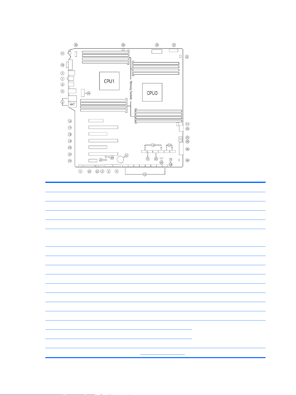
HP Z840 Workstation system board components
I/O PCI/PCIe Power
1 Front audio 16 PCIe3 x4 – CPU0 31 Battery
2 Front USB 3.0 17 PCIe3 x16 – CPU0 32 PCU/memory power
3 Internal USB 2.0 18 PCIe3 x8 – CPU1 33 CPU0/memory power
4 Internal USB 3.0 19 PCIe3 x16 – CPU1 34 CPU1/memory power
5 Keyboard/mouse 20 PCIe2 x8 (4) PCH (single proc)
PCIe3 x8 CPU1 (dual proc)
6 Network 21 PCIe3 x16 – CPU0 36 Main power
7 Rear audio 22 PCIe2 x1 – PCH 37 Rear power button/LED
8 Rear USB 2.0 Cooling Service
9 Rear USB 3.0 23 Auxiliary fan 38 Clear CMOS button
10 Serial 24 CPU/memory fans 39 Boot Block Recovery (BBR) jumper
11 Thunderbolt GPIO 25 CPU0 auxiliary cooler 40 ME/AMT Flash override
SAS/SATA 26 CPU1 auxiliary cooler 41 Password jumper
12 Hard drive LED 27 Front fan 1 (top) 42 Override Option for Slot 5
13 SAS/SATA 6Gb/s 28 Front fan 2 (bottom)
35 Front power button/LED/speaker
14 SATA 6 Gb/s 29 Hard drive thermal jumper
15 sSATA 6 Gb/s 30 Rear chassis fans
NOTE: For related expansion card slot information, see Expansion slots on page 51.
18 Chapter 1 Hardware overview

HP Z840 Workstation system board architecture
●
Dark blue slots are attached to CPU0 and available with CPU0.
●
Purple and gray slots are attached to PCH.
●
White slots are attached to CPU1 and available when CPU1 is installed.
●
Purple/white slots connect to PCH in UP cong and connect to CPU1 in DP cong.
NOTE: The PCIe designators indicate the mechanical connector size and number of electrical PCIe lanes
routed to an expansion slot. For example, x16(8) means that the expansion slot is mechanically a x16 length
connector, with 8 PCIe lanes supported.
HP Z840 Workstation components 19

HP Z840 Workstation specications
Intel Series C612 chipset:
●
Support for the Intel Xeon Processor E5-2600 Series, including processors up to 150 W
●
Processor
technology
Power supply
Memory
technology
Integrated 4-channel memory controller
●
Microarchitecture improvements
●
Large L3 cache for superior performance
●
Intel QuickPath Interconnect (QPI) connects processors and I/O controller with speeds up to 9.6 GT/s
●
850 W Silver, 88% ecient, wide-ranging, active Power Factor Correction, single auxiliary dongle on a
12V rail, ERP 0.5W, Built-in-Self Test (BIST)
●
1125 W Gold, 90% ecient, wide-ranging, active Power Factor Correction, three auxiliary dongles on
three separate 12V rails, ERP 0.5W, Built-in-Self Test (BIST)
●
China’s Energy Conservation Program (CECP) congurations
●
European Union ErP LOT6 2013 power limit of 0.5 W in o mode
●
Dual in-line memory modules (DIMMs) based on DDR4 2133MHz technology
●
Error checking and correcting (ECC)-protected
●
Eight direct-attach memory channels (four per processor) enable low-latency access and fast data
transfer for improved performance
●
Congurations with one processor have eight DIMM slots; a second processor adds eight more DIMM
slots
●
With one processor, up to 1 TB system memory (128 GB DIMMs)
●
With second processor, up to 2 TB system memory (128 GB DIMMs)
●
2133 MHz 4, 8, 16 GB ECC Registered DIMM
●
2133 MHz 32, 64, 128 GB ECC Load Reducing DIMM
NOTE: Do not install memory modules into memory slots if corresponding processor is not installed.
Only Registered and LR ECC DIMMs are supported.
Do not mix any of the dierent types RDIMM [Registered] and LR DIMM [Load Reduction]) of memory. The
system will not boot and will produce a memory error.
For maximum performance, on workstations with two processors, install the same number of DIMMs per
processor and install them in pairs of the same size.
Distribute DIMMs across all memory channels for optimal performance.
Do not install memory modules into memory slots if corresponding processor is not installed.
●
●
Graphics cards
I/O technology
●
NOTE: Not all graphics cards are compatible with all video transceivers and adapters. See the graphics card
documentation for specic details.
●
●
●
●
20 Chapter 1 Hardware overview
PCIe Gen3 (PCIe3) bus speeds; can support three PCIe Gen3 graphics cards in PCIe3 x16 slots
Up to one 150 W or two 75 W graphics cards with 850 W power supply
Up to two 300 W or three 225 W graphics cards with optional 1125 W power supply (other conguration
restrictions may be required)
SAS RAID 0/1/1E/10 on LSI SAS 2308 controller
SATA RAID 0/1/5/10 on sSATA
Six SATA/AHCI ports (2 SATA 6 Gb/s, 4 sSATA 6Gb/s)
Eight SAS ports (6 GB/s)
Loading...