


 Loading...
HP Z238 Workstation
Maintenance and Service Guide
Copyright Information
© Copyright 2016 HP Development Company,
L.P.
First Edition: January 2016
Part number: 838778-001
Warranty
The information contained herein is subject to change without notice. The only warranties for HP products and services are set forth in the express warranty statements accompanying such products and services. Nothing herein should be construed as constituting an additional warranty. HP shall not be liable for technical or editorial errors or omissions contained herein.
Not all features are available in all editions of Windows. This computer may require upgraded and/or separately purchased hardware, drivers, and/or software to take full advantage of Windows functionality. See http://www.microsoft.com for details.
Trademark Credits
ENERGY STAR is a registered trademark owned by the U.S. Environmental Protection Agency (EPA).
Intel, Core, Pentium, and Xeon are trademarks are trademarks of Intel Corporation in the U.S. and other countries.
Microsoft and Windows are either registered trademarks or trademarks of Microsoft Corporation in the United States and/or other countries.
NVIDIA and the NVIDIA logo are trademarks and/or registered trademarks of NVIDIA Corporation in the U.S. and other countries.

About this guide
This guide provides service and maintenance information, technical details, and con guration guidance for your workstations.
 IMPORTANT: Removal and replacement procedures are now available in videos on the HP website.
Go to http://www.hp.com/go/sml.
Guide topics
Hardware overview on page 1
System management on page 10
Component replacement information and guidelines on page 35
Diagnostics and troubleshooting on page 48
Con guring password security and resetting CMOS on page 70
Con guring RAID devices on page 76
System board designators on page 80
 NOTE: View the HP Workstation User Guide for your workstation at http://www.hp.com/support/ workstation_manuals.
iii
iv About this guide

Table of contents
1 Hardware overview ........................................................................................................................................ |
1 |
HP Z238 Workstation components ....................................................................................................................... |
2 |
Front panel .......................................................................................................................................... |
2 |
Rear panel ............................................................................................................................................ |
3 |
Chassis components ............................................................................................................................ |
4 |
System board components ................................................................................................................. |
5 |
System board architecture .................................................................................................................. |
6 |
Workstation speci cations .................................................................................................................. |
7 |
Product speci cations ........................................................................................................................................... |
8 |
Workstation weights and dimensions ................................................................................................. |
8 |
Environmental speci cations .............................................................................................................. |
8 |
Ensuring proper ventilation ................................................................................................................................... |
9 |
2 System management ................................................................................................................................... |
10 |
Power management and performance features ................................................................................................. |
10 |
ERP compliance mode ....................................................................................................................... |
10 |
Hyper-Threading Technology (HTT) .................................................................................................. |
11 |
SATA Power Management ................................................................................................................. |
11 |
Intel Turbo Boost Technology ........................................................................................................... |
11 |
BIOS ROM ............................................................................................................................................................. |
11 |
Computer Setup (F10) utilities ............................................................................................................................ |
12 |
Using Computer Setup (F10) utilities ................................................................................................ |
12 |
Computer Setup–Main ....................................................................................................................... |
14 |
Computer Setup—Security ............................................................................................................... |
16 |
Computer Setup—Advanced ............................................................................................................. |
18 |
Desktop management ......................................................................................................................................... |
23 |
Initial computer con guration and deployment ............................................................................... |
24 |
Installing a remote system ............................................................................................................... |
24 |
Copying a setup con guration to another computer ....................................................................... |
24 |
Updating and managing software .................................................................................................... |
25 |
HP Client Management Solutions ..................................................................................................... |
25 |
Altiris Client Management Solutions ................................................................................................. |
25 |
HP SoftPaq Download Manager ........................................................................................................ |
26 |
System Software Manager ................................................................................................................ |
26 |
ROM Flash .......................................................................................................................................... |
26 |
Remote ROM Flash .......................................................................................................... |
26 |
v
HPQFlash ......................................................................................................................... |
26 |
FailSafe Boot Block ............................................................................................................................ |
26 |
Recovering the computer by using FailSafe Boot Block recovery mode ........................ |
27 |
Workstation security ......................................................................................................................... |
27 |
Asset tracking ................................................................................................................. |
27 |
SATA hard drive security ................................................................................................. |
28 |
DriveLock applications ................................................................................. |
28 |
Using DriveLock ............................................................................................ |
29 |
Password security ........................................................................................................... |
30 |
Establishing an administrator password using Computer Setup (F10) |
|
Utility ............................................................................................................ |
30 |
Establishing a power-on password using Computer Setup (F10) Utility ..... |
31 |
Entering a power-on password .................................................................... |
31 |
Entering an administrator password ........................................................... |
32 |
National keyboard delimiter characters ...................................................... |
32 |
Clearing passwords ...................................................................................... |
32 |
Chassis security .............................................................................................................. |
33 |
Smart Cover Sensor (optional) ..................................................................... |
33 |
Side access panel solenoid lock ................................................................... |
33 |
Cable lock (optional) ..................................................................................... |
33 |
Fault noti cation and recovery ......................................................................................................... |
33 |
ECC fault prediction ......................................................................................................... |
34 |
Thermal sensors ............................................................................................................. |
34 |
Programmable power button (Windows only) .................................................................................. |
34 |
Changing the power button con guration (Windows only) ........................................... |
34 |
3 Component replacement information and guidelines ...................................................................................... |
35 |
Warnings and cautions ........................................................................................................................................ |
36 |
Service considerations ......................................................................................................................................... |
36 |
Tools and software requirements ..................................................................................................... |
36 |
Electrostatic discharge (ESD) information ........................................................................................ |
37 |
Product recycling ................................................................................................................................................. |
38 |
Component replacement guidelines ................................................................................................................... |
38 |
Battery ............................................................................................................................................... |
39 |
Cable management ........................................................................................................................... |
39 |
CPU (processor) and CPU heatsink .................................................................................................... |
40 |
Expansion slots ................................................................................................................................. |
41 |
Card con guration restrictions for power supplies ........................................................ |
41 |
Choosing an expansion card slot .................................................................................... |
41 |
Workstation slot identi cation and description ............................................................. |
42 |
Workstation installation sequence recommendations .................................................. |
43 |
vi
Hard drives and optical disc drives ................................................................................................... |
43 |
Handling hard drives ....................................................................................................... |
43 |
Removal and replacement tips ....................................................................................... |
43 |
Drive installation and cabling scenarios ......................................................................... |
44 |
SATA cable connection guidelines ................................................................ |
44 |
Memory .............................................................................................................................................. |
44 |
Supported DIMM con gurations ..................................................................................... |
44 |
BIOS errors and warnings ............................................................................................... |
44 |
DIMM installation guidelines .......................................................................................... |
44 |
DIMM installation order .................................................................................................. |
45 |
Power supply ..................................................................................................................................... |
46 |
Power supply speci cations ........................................................................................... |
46 |
Power consumption and heat dissipation ...................................................................... |
46 |
Resetting the power supply ............................................................................................ |
46 |
System board .................................................................................................................................... |
47 |
System cabling ................................................................................................................ |
47 |
4 Diagnostics and troubleshooting .................................................................................................................. |
48 |
Contacting support .............................................................................................................................................. |
48 |
Locating ID labels ................................................................................................................................................ |
49 |
Locating warranty information ........................................................................................................................... |
49 |
Diagnosis guidelines ............................................................................................................................................ |
49 |
Diagnosis at startup .......................................................................................................................... |
49 |
Diagnosis during operation ............................................................................................................... |
50 |
Troubleshooting checklist ................................................................................................................................... |
50 |
HP troubleshooting resources and tools ............................................................................................................. |
51 |
Online support ................................................................................................................................... |
51 |
HP Support Center .......................................................................................................... |
51 |
HP Chat Support .............................................................................................................. |
51 |
Customer Advisories, Customer and Security Bulletins, and Customer Notices ........... |
51 |
Product Change Noti cations ....................................................................... |
52 |
Helpful hints ...................................................................................................................................... |
52 |
At startup ........................................................................................................................ |
52 |
During operation ............................................................................................................. |
52 |
Customer Self Repair ...................................................................................................... |
53 |
More troubleshooting options ........................................................................................ |
53 |
Troubleshooting scenarios and solutions ........................................................................................................... |
54 |
Solving minor problems .................................................................................................................... |
54 |
Solving hard drive problems ............................................................................................................. |
55 |
Solving printer problems ................................................................................................................... |
56 |
Solving display problems .................................................................................................................. |
57 |
vii
|
Solving audio problems ..................................................................................................................... |
59 |
|
Solving power supply problems ........................................................................................................ |
60 |
|
Testing power supply ...................................................................................................... |
60 |
Using HP PC Hardware Diagnostics (UEFI) ........................................................................................................... |
61 |
|
|
Downloading HP PC Hardware Diagnostics (UEFI) to a USB device .................................................. |
61 |
POST error messages and diagnostic front panel LEDs and audible codes ....................................................... |
62 |
|
|
POST numeric codes and text messages .......................................................................................... |
63 |
Interpreting system validation diagnostic front panel LEDs and audible codes ................................................ |
68 |
|
5 on ur n |
password security and resetting CMOS ........................................................................................ |
70 |
Preparing to con gure passwords ...................................................................................................................... |
70 |
|
Resetting the password jumper .......................................................................................................................... |
70 |
|
Clearing and resetting the BIOS ........................................................................................................................... |
71 |
|
Appendix A Linux technical notes .................................................................................................................... |
73 |
|
System RAM ......................................................................................................................................................... |
73 |
|
Audio .................................................................................................................................................................... |
73 |
|
Network cards ...................................................................................................................................................... |
74 |
|
Hyper-Threading Technology .............................................................................................................................. |
74 |
|
NVIDIA Graphics Workstations ............................................................................................................................. |
74 |
|
AMD Graphics Workstations ................................................................................................................................ |
75 |
|
Appendix B |
on ur n RAID devices ............................................................................................................... |
76 |
RAID hard drive maximum and associated storage controller options .............................................................. |
76 |
|
Supported RAID con gurations ........................................................................................................................... |
77 |
|
Con guring Intel SATA RAID ................................................................................................................................. |
77 |
|
|
Con guring system BIOS ................................................................................................................... |
77 |
|
Con guring RAID with the Intel utility .............................................................................................. |
78 |
Software RAID solution ........................................................................................................................................ |
78 |
|
|
Software RAID considerations .......................................................................................................... |
78 |
|
Performance considerations ............................................................................................................. |
79 |
|
Con guring software RAID ................................................................................................................ |
79 |
Appendix C System board designators ............................................................................................................. |
80 |
|
System board designators ................................................................................................................................... |
80 |
|
Index ............................................................................................................................................................. |
|
82 |
viii

1Hardware overview
This chapter presents an overview of workstation hardware components.
Topics
HP Z238 Workstation components on page 2
Product speci cations on page 8
Ensuring proper ventilation on page 9
1
HP Z238 Workstation components
This section describes the HP Z238 Workstation components.
For complete and current information on supported accessories and components for the computer, see http://partsurfer.hp.com.
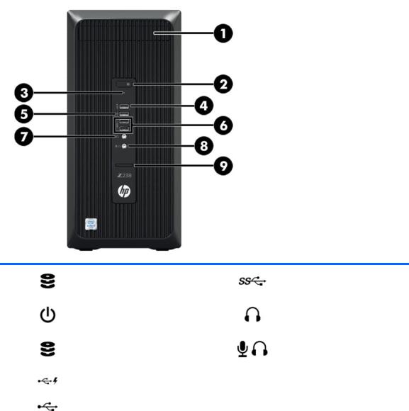
Front panel
1 |
Optional optical disc drive (not shown) |
6 |
USB 3.0 ports, SuperSpeed (2) |
|
|
|
|
2 |
Power button |
7 |
Headphone jack |
|
|
|
|
3 |
Hard disk drive activity light |
8 |
Headphone/microphone combo jack |
|
|
|
|
4 |
USB 2.0 port (1), charging |
9 |
Optional media card reader (shown) |
|
|
|
|
5 |
USB 2.0 port (1) |
|
|
|
|
|
|
2Chapter 1 Hardware overview
Rear panel
1 |
PS/2 keyboard connector (purple) |
7 |
RJ-45 network connector |
|
|
||||
|
|
|
|
|
2 |
PS/2 mouse connector (green) |
8 |
USB 3.0 ports, SuperSpeed (6) |
|
|
|
|
|
|
3 |
Dual-Mode Display Port (DP) connectors |
9 |
Audio line-out connector (green) |
|
(3) |
||||
|
|
|
||
|
|
|
|
|
4 |
Padlock loop |
10 |
Audio line-in connector (blue) |
|
|
|
|
|
|
5 |
Serial port |
11 |
Power cord connector |
6Cable lock slot
NOTE: The labels for the rear panel connectors use industry-standard icons and colors.
NOTE: |
The DP ports are not supported when the system is con gured with Intel Xeon® E3-12x0 v5 processors. Also, if a discrete graphics card is installed these |
ports are disabled by default. |
|
NOTE: |
Simultaneous usage of integrated Intel HD graphics and discrete graphics cards (in order to drive more than two displays) can be enabled using the |
Computer (F10) Setup Utility. However, HP recommends using only discrete graphics cards when attaching three or more displays.
HP Z238 Workstation components |
3 |
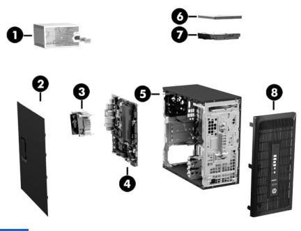
Chassis components
The following gure shows the chassis components of a typical workstation layout. Drive con gurations can vary.
Item |
Description |
Item |
Description |
|
|
|
|
1 |
Power supply |
5 |
Chassis |
|
|
|
|
2 |
Side access panel |
6 |
Slim optical drive |
|
|
|
|
3 |
Cooler/heat sink |
7 |
Hard drive |
|
|
|
|
4 |
System board |
8 |
Front bezel |
|
|
|
|
4Chapter 1 Hardware overview
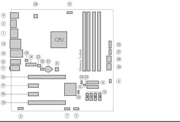
System board components
The following illustration and table identify the system board components for the workstation.
|
I/O |
|
SATA |
|
Power |
|
|
|
|
|
|
1 |
DisplayPort (dual) |
15 |
AHCI 6Gb/s |
23 |
Battery |
|
|
|
|
|
|
2 |
DisplayPort (single) |
|
PCI/PCIe |
24 |
Processor power |
|
|
|
|
|
|
3 |
Front audio |
16 |
PCIe3 x16 |
25 |
Front power button/LED |
|
|
|
|
|
|
4 |
Front speaker |
17 |
PCIe3 x1 |
26 |
Main power |
|
|
|
|
|
|
5 |
Front USB 2.0 |
18 |
PCIe3 x1 |
27 |
Power COMM |
|
|
|
|
|
|
6 |
Front USB 3.0 |
19 |
PCIe3 x16 (4) |
28 |
SATA power |
|
|
|
|
|
|
7 |
Internal USB 2.0 |
20 |
Z turbo drive LED (E19) |
|
Security |
|
|
|
|
|
|
8 |
Internal USB 3.0 |
NOTE: For related expansion card |
29 |
Chassis solenoid lock |
|
|
|
slot information, see Expansion slots |
|
|
|
|
|
|
on page 41 |
|
|
|
|
|
|
|
|
9 |
Keyboard/mouse |
|
Cooling |
30 |
Hood sensor |
|
|
|
|
|
|
10 |
Network/rear USB 3.0 |
21 |
Processor fan |
|
Service |
|
|
|
|
|
|
11 |
Rear audio |
22 |
Rear fan |
31 |
Clear CMOS button |
|
|
|
|
|
|
12 |
Rear USB 3.0 |
|
|
32 |
ME/AMT flash override |
|
|
|
|
|
|
13 |
Serial |
|
|
33 |
Password jumper |
|
|
|
|
|
|
14 |
Header for serial adapter |
|
|
|
|
|
|
|
|
|
|
HP Z238 Workstation components |
5 |

System board architecture
 NOTE: The PCIe designators indicate the mechanical connector size and number of electrical PCIe lanes routed to an expansion slot. For example, x16(4) means that the expansion slot is mechanically a x16 length connector, with 4 PCIe lanes supported.
6Chapter 1 Hardware overview
Workstation spec |
c t ons |
||
|
|
|
|
|
|
● |
Intel Series C236 chipset |
|
|
● |
Support for the Intel Xeon Processor E3 v5 Family or sixth-generation Intel Core processors up to 80 W |
|
|
● |
Integrated 2-channel memory controller |
|
Processor |
● |
Microarchitecture improvements |
|
technology |
||
|
|
|
|
|
|
● |
Integrated graphics (some models) |
|
|
● |
Advanced Vector Extensions (AVX) to increase floating point performance |
|
|
● |
Intel DMI3 interface connecting the processor to the I/O controller |
|
|
|
|
|
Power supply |
● |
280 W, 85% efficient, compatible with ENERGY STAR Version 6.1 requirements |
|
|
|
|
|
|
● |
Dual in-line memory modules (DIMMs) based on DDR4 2133MHz technology |
|
|
● |
Supports error checking and correcting (ECC) and non-ECC DIMMs |
|
Memory |
● |
Two direct-attach memory channels enable low-latency access and fast data transfer |
|
|
|
|
|
technology |
● |
Up to 64 GB system memory (16 GB DIMMs) |
|
|
||
|
|
● |
2133 MHz 4, 8, 16 GB ECC unbu ered DIMM |
|
|
● |
2133 MHz 4, 8, 16 GB non ECC unbu ered DIMM |
|
|
|
|
|
|
● |
Up to PCIe Gen 3 bus speeds. |
|
|
● |
PCIe x16 cards are supported in the x16 slot closest to the processor. |
|
|
● |
Up to three displays with integrated Intel HD graphics (depending on processor type). |
|
|
● |
Windows 10 supports display output from both integrated graphics capable processors and discrete |
|
Graphics cards |
|
graphics cards. This feature can be changed through the Computer Setup (F10) Utility. |
|
|
NOTE: Most supported Intel Core processors provide Intel HD Graphics 510/530; Intel Xeon processors with |
|
|
|
model designations that end in "___5" provide Intel HD Graphics P530. |
|
|
|
NOTE: To drive more than three displays, use Computer Setup (F10) Utility to intermix integrated Intel HD |
|
|
|
graphics and discrete graphics cards (with four or more displays, HP recommends using only discrete |
|
|
|
graphics cards). |
|
|
|
|
|
|
|
● |
RAID con gurations for SATA RAID levels 0, 1 |
|
|
● |
Two external and one internal USB 2.0 ports |
|
I/O technology |
● |
Eight external and one internal USB 3.0 port |
|
|
● |
Three DisplayPort 1.2 connectors |
|
|
● |
Serial header that can be used with an optional PCI bulkhead connector |
|
|
|
|
HP Z238 Workstation components |
7 |

Product spec c t ons
Workstation weights and dimensions
Characteristic |
|
|
HP Z238 |
|
|
|
|
|
Typical con guration |
6.99 kg (15.38 lb) |
|
Weight |
|
|
|
Minimum con |
guration |
6.42 kg (14.12 lb) |
|
|
|
|
|
|
Maximum con |
guration |
7.9 kg (17.42 lb) |
|
|
|
|
|
Height |
|
35.5 cm (14.0 in) |
Chassis dimensions |
|
|
|
Width |
|
16.5 cm (6.5 in) |
|
|
|
|
|
|
Depth |
|
35.6 cm (14.1 in) |
|
|
|
|
Environmental spec |
c t ons |
|
|
|
|
|
Characteristic |
Z238 Workstation |
|
|
|
|
|
Operating: 5°C to 35°C (40°F to 95°F) |
|
Temperature |
Non-operating: -40°C to 60°C (-40°F to 140°F) |
|
|
NOTE: Derate by 1°C (1.8°F) for every 305 m (1,000 ft) altitude over 1,524 m (5,000 ft). |
|
|
|
|
Humidity |
Operating: 8% to 85% relative humidity, non-condensing |
|
Non-operating: 8% to 90% relative humidity, non-condensing |
|
|
|
|
|
|
|
|
Altitude |
Operating: 0 to 3,048 m (10,000 ft) |
|
Non-operating: 0 to 9,144 m (30,000 ft) |
|
|
|
|
|
|
|
8Chapter 1 Hardware overview
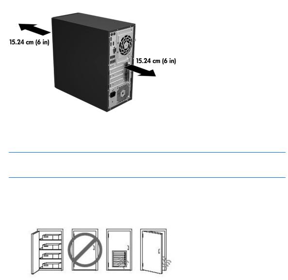
Ensuring proper ventilation
Proper ventilation for the system is important for workstation operation. Follow these guidelines:
●Operate the workstation on a sturdy, level surface.
●Provide at least 15.24 cm (6 inches) of clearance at the front and back of the workstation. (Workstation models vary.)
●Be sure that the ambient air temperature falls within the environmental speci cations listed in this document.
 NOTE: The ambient upper limit of 35°C (95°F) is only good up to 1524 m (5000 ft) elevation. There is a 1°C (33.8°F) per 304.8 m (1000 ft) derating above 1524 m (5000 ft). So, at 3,048 m (10,000 ft), the upper ambient air temperature limit is 30°C (86°F).
●For cabinet installation, be sure that adequate cabinet ventilation and the ambient temperature within the cabinet does not exceed speci ed limits.
●Never restrict the incoming or outgoing airflow of the workstation by blocking any vents or air intakes,
as shown in the following gure.
Ensuring proper ventilation |
9 |

2System management
This section describes the tools and utilities that provide system management for the workstation.
Topics
Power management and performance features on page 10
BIOS ROM on page 11
Computer Setup (F10) utilities on page 12
Desktop management on page 23
Power management and performance features
ERP compliance mode
This computer provides ERP compliance mode capability.
When enabled, the computer shuts down to the lowest possible power state. The computer must then be turned on with the power button. One of the e ects is that "wake on LAN" is disabled.
When disabled, the computer powers down conventionally.
1.Press F10 during startup.
2.Using the arrow keys, select the Advanced > Power Management Options, and then select S5 Maximum Power Savings.
3.Select Main > Save Change and Exit, and then press enter to accept the change.
Enabling ERP compliance mode
4. If using Windows, boot to Windows and search in the Start Menu for the setting Choose what the power buttons do. Clear Turn on fast startup (recommended). If the check box is not available, select Change settings that are currently unavailable at the top of the window.
If using Windows 10, use the taskbar search eld to search for Power Options. Select Choose what the power button does, then select Turn on fast startup (recommended).
|
1. |
Press F10 during startup. |
|
2. |
Using the arrow keys, select Advanced > Power Management Options, then clear S5 |
|
|
Maximum Power Savings. |
Disabling ERP compliance |
3. |
Select Main > Save Change and Exit, and then press enter to accept the change. |
|
|
|
mode |
4. |
If using Windows, boot to Windows and search in the Start Menu for the setting Choose what |
|
|
the power buttons do. Check Turn on fast startup (recommended). If the check box is not |
|
|
available, select Change settings that are currently unavailable at the top of the window. |
If using Windows 10, use the taskbar search eld to search for Power Options. Select Choose what the power button does, then select Turn on fast startup (recommended).
10 Chapter 2 System management
Hyper-Threading Technology (HTT)
This computer supports HTT, an Intel-proprietary technology that improves processor performance through parallelization of computations (doing multiple tasks at once).
The operating system treats an HTT-enabled processor as two virtual processors, and shares the workload between them when possible. This feature requires that the operating system support multiple processors and be speci cally optimized for HTT.
Use Computer Setup (F10) Utility to enable HTT.
Go to http://www.hp.com/go/quickspecs to determine if your CPU supports HTT.
SATA Power Management
SATA Power Management enables or disables SATA bus and/or device power management.
Intel Turbo Boost Technology
Your workstation supports Intel® Turbo Boost Technology.
This feature enables the CPU to run at a higher than normal rate. When all CPU cores are not necessary for the workload, inactive cores are turned o and power is diverted to the active cores to increase their performance.
Turbo Boost is enabled and disabled with Computer Setup (F10) Utility.
Go to http://www.hp.com/go/quickspecs to determine if your CPU supports Turbo Boost.
BIOS ROM
The BIOS ROM is a collection of machine language applications stored as rmware in ROM. It includes functions such as Power-On Self-Test (POST), PCI device initialization, Plug and Play support, power management, and Computer Setup (F10) Utility.
Go to http://www.hp.com/go/quickspecs to review the latest BIOS ROM speci cations.
BIOS ROM 11

Computer Setup (F10) utilities
Use Computer Setup (F10) Utility to do the following:
●Change settings from the defaults or restore the settings to default values.
●View the system con guration, including settings for processor, graphics, memory, audio, storage, communications, and input devices.
●Modify the boot order of bootable devices such as hard drives, optical drives, or USB flash media devices.
●(Windows 7 only) Establish an Ownership Tag, the text of which is displayed each time the system is turned on or restarted.
●Enter the Asset Tag or property identi cation number assigned by the company to this computer.
●Enable the power-on password prompt during system restarts (warm boots) as well as during power-on.
●Establish an administrator password that controls access to the Computer Setup (F10) Utility and the settings described in this section.
●Establish minimum requirements for valid passwords, including length and required types of characters.
●Secure integrated I/O functionality, including the serial, USB, or audio, or embedded NIC, so that they cannot be used until they are unsecured.
●Enable or disable di erent types of boot sources.
●Con gure features such as Secure Boot, power management, virtualization support, and language and keyboard type used in Setup and POST.
●Replicate the system setup by saving system con guration information on a USB device and restoring it on one or more computers.
●Enable or disable DriveLock security or securely erase a hard drive (when supported by drive).
Using Computer Setup (F10) utilities
Computer Setup can be accessed only by turning the computer on or restarting the system. To access the Computer Setup Utilities menu, complete the following steps:
1.Turn on or restart the computer.
2.Repeatedly press F10 when the monitor light turns on to access the utility.
You can also press esc to a menu that allows you to access di erent options available at startup, including the Computer Setup utility.
 NOTE: If you do not press F10 at the appropriate time, you must restart the computer and again repeatedly press F10 when the monitor light turns green to access the utility.
3.A choice of four headings appears in the Computer Setup Utilities menu: Main, Security, Advanced, and UEFI Drivers.
 NOTE: Selecting UEFI Drivers restarts the computer into the 3rd party option ROM management application. You can access this application directly by pressing F3 during startup.
4.Use the arrow (left and right) keys to select the appropriate heading. Use the arrow (up and down) keys to select the option you want, then press enter. To return to the Computer Setup Utilities menu, press esc.
5.To apply and save changes, select Main > Save Changes and Exit.
12 Chapter 2 System management
●If you have made changes that you do not want applied, select Ignore Changes and Exit.
●To restore settings from the Advanced and Main menus to original values, select Apply Factory Defaults and Exit.
●To restore settings from the Advanced and Main menus to those previously saved by Save Custom Defaults, select Apply Custom Defaults and Exit. If no custom defaults have been saved, then factory defaults are used.
 NOTE: Settings in the Security menu are not modi ed by Apply Defaults. Those values are reset by
Restore Security Settings to Factory Defaults at the bottom of the Security menu.
 NOTE: Not all settings shown in the following sections are available for all models
 CAUTION: Do NOT turn the computer power OFF while the BIOS is saving the Computer Setup (F10) changes because the settings could become corrupted. It is safe to turn o the computer only after exiting the F10 Setup screen.
Computer Setup (F10) utilities 13

Computer Setup–Main
 NOTE: Support for speci c Computer Setup options may vary depending on the hardware con guration.
Table 2-1 Computer Setup—Main
Option |
Description |
|
|
|
|
System Information |
Lists all information in the following list if Advanced System Information is selected. Lists smaller subset |
|
|
if Basic System Information is selected. |
|
|
● |
Product name |
|
● |
Installed memory size |
|
● |
Processor type |
|
● |
Processor cache size (L1/L2/L3) |
|
● |
Processor speed |
|
● |
MicroCode Revision |
|
● |
Processor Stepping |
|
● |
Memory Speed |
|
● |
DIMM size (for each installed module) |
|
● |
System BIOS version |
|
● |
ME Firmware version |
|
● |
Video BIOS version |
|
● |
Super I/O Firmware version |
|
● |
Born On Date |
|
● |
Serial Number |
|
● |
SKU number |
|
● |
UUID (Universally Unique denti er) |
|
● |
Asset Tracking Number |
|
● |
Feature Byte |
|
● |
Build ID |
|
● |
Product Family |
|
● |
System Board ID |
|
● |
System Board CT |
|
● |
Integrated MAC Address |
|
|
|
System Diagnostics |
If the hard drive has the HP Advanced Diagnostics installed, the application will launch. If HP Advanced |
|
|
Diagnostics is not installed, then a basic version built into the BIOS will provide the capability to perform |
|
|
the following functions: |
|
|
● |
Memory Test |
|
● |
Hard Drive Check |
|
● |
Language |
|
|
|
Update System BIOS |
Lets you update the system BIOS from www.hp.com or another network server, from a removable USB |
|
|
drive, or from a le located on the hard drive. |
|
|
● |
‘Check HP.com for BIOS Updates’ or ‘Check the Network for BIOS Updates’ |
14 Chapter 2 System management

Table 2-1 Computer Setup—Main (continued)
|
|
The string that appears here depends on the setting in ‘BIOS Update Preferences’. |
|
|
● |
Lock BIOS Version |
|
|
|
If this option is selected, the system is locked to the current BIOS version and updates are not |
|
|
|
allowed. |
|
|
● |
BIOS Update Preferences |
|
|
|
Allows the administrator to select the source of network updates (www.hp.com or another network |
|
|
|
server) and allows con guration of a periodic check for updates, including policies for: |
|
|
|
■ |
Check for updates and prompt the user to accept or reject the update at that time |
|
|
■ |
Check for updates and install all new versions |
|
|
■ |
Check for updates and install only new versions marked important |
|
● |
Network Con guration Settings |
|
|
● |
Update BIOS Using Local Media |
|
|
|
Lets you access les on either USB storage or the hard drive. The HP BIOS Update and Recovery |
|
|
|
application included in BIOS Softpaqs at www.hp.com will copy the BIOS le to the correct location |
|
|
|
on the hard drive or USB device. |
|
|
|
||
System IDs |
Lets you set the following values: |
||
|
● |
Asset Tracking Number |
|
|
● |
Ownership Tag |
|
|
|
||
Replicated Setup |
Backup current settings to USB device |
||
|
Saves system con guration to a formatted USB flash media device. |
||
|
Restore current settings from USB device |
||
|
Restores system con guration from a USB flash media device. |
||
|
|
||
Save Custom Defaults |
Saves the current system con guration settings as the custom default set. |
||
|
|
||
Apply Custom Defaults |
Applies the custom default settings to the computer after rebooting. Does not apply to options in the |
||
and Exit |
Security menu. |
||
|
|
||
Apply Factory Defaults |
Restores the factory system con guration settings to the computer after rebooting. Does not apply to |
||
and Exit |
options in the Security menu. |
||
|
|
||
Ignore Changes and Exit |
Exits Computer Setup without applying or saving any changes. |
||
|
|
||
Save Changes and Exit |
Saves changes to current system con guration, exits Computer Setup, and reboots. |
||
|
|
|
|
Computer Setup (F10) utilities 15

Computer Setup—Security
 NOTE: Support for speci c Computer Setup options may vary depending on the hardware con guration.
Table 2-2 Computer Setup—Security
Option |
Description |
|
|
|
|
Set up BIOS |
Lets you set and enable a BIOS administrator password, which includes the following privileges: |
|
Administrator Password |
|
|
|
● |
Manage other BIOS users |
|
● |
Full access to BIOS policy and settings |
|
● |
Unlock the computer when other BIOS users fail the preboot authentication. |
|
NOTE: Creating a BIOS user disables the Fast Boot option. |
|
|
NOTE: If the password is set, it is required to change Computer Setup options, update the BIOS, and |
|
|
make changes to certain plug and play settings under Windows. |
|
|
|
|
Change BIOS |
Lets you change the BIOS administrator password. |
|
Administrator Password |
You must know the current password to be able to change it. |
|
|
||
(This selection is active |
|
|
only if a BIOS |
|
|
administrator password is |
|
|
set.) |
|
|
|
|
|
Password Policies |
Lets you set the guidelines for a valid password. Options include: |
|
|
● |
Password minimum length |
|
● |
Requires at least one symbol |
|
● |
Requires at least one number |
|
● |
Requires at least one upper case character |
|
● |
Requires at least one lower case character |
|
● |
Allows spaces |
|
Clear Password Jumper |
|
|
Select ‘Honor’ to allow or ‘Ignore’ to not allow the absence of the password jumper to clear the passwords |
|
|
at boot up. Default is ‘Honor’. |
|
|
|
|
Security on ur t on |
TPM Embedded Security |
|
|
● |
TPM Device |
|
|
Lets you set the Trusted Platform Module as available or hidden. |
|
● |
TPM State |
|
|
Select to enable the TPM. |
|
● |
TPM Clear |
|
|
Select to reset the TPM to an unowned state. After the TPM is cleared, it is also turned o . To |
|
|
temporarily suspend TPM operations, turn the TPM o instead of clearing it. |
|
|
CAUTION: Clearing the TPM resets it to factory defaults and turns it o . You will lose all created |
|
|
keys and data protected by those keys. |
|
BIOS Sure Start |
|
|
● |
Verify Boot Block on every Boot |
|
|
Select to check validity of boot block region each boot. If not selected, boot block region will be |
|
|
validated on power cycles. |
16 Chapter 2 System management

Table 2-2 Computer Setup—Security (continued)
|
● |
Data Recovery Policy |
|
|
Select ‘Automatic’ or ‘Manual’ to set data recovery policy. ‘Manual’ lets you select whether or not to |
|
|
execute recovery of a corrupted region if it is detected. |
|
Dynamic Runtime Scanning of Boot Block |
|
|
Veri |
es the integrity of the BIOS boot block region several times each hour while the system is running. |
|
|
|
Set Up BIOS Power-On |
Lets you set and enable a BIOS power-on password. The power-on password prompt appears after a |
|
Password |
power cycle or reboot. If the user does not enter the correct power-on password, the unit will not boot. |
|
|
|
|
Change BIOS Power-On |
Lets you change the BIOS power-on password. |
|
Password |
You must know the current password to be able to change it. |
|
|
||
(This selection is active |
|
|
only if a BIOS power-on |
|
|
password is set.) |
|
|
|
|
|
DriveLock |
Allows you to assign or modify a master or user password for hard drives. When this feature is enabled, |
|
|
the user is prompted to provide one of the DriveLock passwords during POST. If neither is successfully |
|
|
entered, the hard drive will remain inaccessible until one of the passwords is successfully provided during |
|
|
a subsequent cold-boot sequence. |
|
|
NOTE: This selection will only appear when at least one drive that supports the DriveLock feature is |
|
|
attached to the system. |
|
|
CAUTION: Be aware that these settings take place immediately. A save is not necessary. |
|
|
CAUTION: Be sure to document the DriveLock password. Losing a DriveLock password will render a drive |
|
|
permanently locked. |
|
|
After you select a drive, the following options are available: |
|
|
Set DriveLock Master Password. Sets the drive’s master password but does not enable DriveLock. |
|
|
Enable DriveLock. Sets the drive’s user password and enables DriveLock. |
|
|
|
|
Secure Erase |
Lets you select a hard drive to completely erase. |
|
|
Once a hard drive has been erased with a program that utilizes Secure Erase rmware commands, no le |
|
|
recovery program, partition recovery program, or other data recovery method will be able to extract data |
|
|
from the drive. |
|
|
|
|
Save/Restore MBR of the |
NOTE: Windows 10 systems are generally not formatted to include an MBR. Instead they use GUID |
|
system hard drive |
Partition Table (GPT) format, which better supports large hard drives. |
|
|
Enabling this feature will save the Master Boot Record (MBR) of the system hard drive. If the MBR gets |
|
|
changed, the user will be prompted to restore the MBR. Default is disabled. |
|
|
The MBR contains information needed to successfully boot from a disk and to access the data stored on |
|
|
the disk. Master Boot Record Security may prevent unintentional or malicious changes to the MBR, such as |
|
|
those caused by some viruses or by the incorrect use of certain disk utilities. It also allows you to recover |
|
|
the "last known good" MBR, should changes to the MBR be detected when the system is restarted. |
|
|
NOTE: Most operating systems control access to the MBR of the current bootable disk; the BIOS cannot |
|
|
prevent changes that may occur while the operating system is running. |
|
|
Restores the backup Master Boot Record to the current bootable disk. Default is disabled. |
|
|
Only appears if all of the following conditions are true: |
|
|
● |
MBR security is enabled |
|
● |
A backup copy of the MBR has been previously saved |
|
● |
The current bootable disk is the same disk from which the backup copy was saved |
Computer Setup (F10) utilities 17

Table 2-2 Computer Setup—Security (continued)
|
CAUTION: Restoring a previously saved MBR after a disk utility or operating system has modi ed the |
|
|
MBR, may cause the data on the disk to become inaccessible. Only restore a previously saved MBR if you |
|
|
are con |
dent that the current bootable disk's MBR has been corrupted or infected with a virus. |
|
|
|
Smart Cover |
Cover Lock (Lock/Unlock) |
|
|
Default is ‘Unlock’. |
|
|
Cover Removal Sensor (Disabled/Notify user/Administrator password) |
|
|
Lets you disable the cover sensor or con gure what action is taken if the computer cover was removed. |
|
|
Default is ‘Disabled’. |
|
|
NOTE: |
Notify user alerts the user with a POST error on the rst boot after the sensor detects removal of |
|
the cover. If the password is set, Administrator Password requires that the password be entered to boot |
|
|
the computer if the sensor detects that the cover has been removed. |
|
|
|
|
System Management |
Allows authorized personnel to reset security settings during a service event. Default is enabled. |
|
Command |
|
|
|
|
|
Restore Security |
This action resets security devices, clears BIOS passwords (not including DriveLock), and restores settings |
|
Settings to Default |
in the Security menu to factory defaults. |
|
|
|
|
Computer Setup—Advanced
 NOTE: Support for speci c Computer Setup options may vary depending on the hardware con guration.
Table 2-3 Computer Setup—Advanced (for advanced users)
Option |
Heading |
|
|
|
|
||
Display Language |
Lets you select the language of the menus in F10 Setup and the keyboard layout. |
||
|
|
||
Scheduled Power-On |
This feature wakes the system up from a powered-o state at a speci ed date and time. |
||
|
|
||
Boot Options |
Select the devices that the computer can boot from, as well as other options, including: |
||
|
● |
Startup Menu Delay(sec). Enabling this feature will add a user-speci ed delay to the POST process. |
|
|
|
One purpose for the delay is to provide additional time to activate hotkeys such as esc for the |
|
|
|
Startup Menu or F10 for Computer Setup. |
|
|
● |
Fast Boot. Default is enabled for Windows 10 and disabled for Windows 7 systems. |
|
|
● |
CD-ROM Boot. Default is enabled. |
|
|
● |
Network (PXE) Boot. Default is enabled. |
|
|
● |
Prompt on Memory Size Change. Default is enabled. |
|
|
● |
Prompt on Fixed Storage Change. Default is disabled. |
|
|
● |
After Power Loss. Default is Power O . |
|
|
|
■ |
Power o —causes the computer to remain powered o when power is restored. |
|
|
■ |
Power on—causes the computer to power on automatically as soon as power is restored. |
|
|
■ |
Previous state—causes the computer to power on automatically as soon as power is restored, |
|
|
|
if it was on when power was lost. |
NOTE: If the system is con gured to ‘Power On from Keyboard Ports’ (see Power Management
Options), then this setting is forced to ‘Power On’.
●Audio Alerts During Boot. Default is enabled. When disabled, most audible beeps from errors, warnings, and password prompts during boot up are suppressed.
●UEFI Boot Order.
18 Chapter 2 System management

Table 2-3 Computer Setup—Advanced (for advanced users) (continued)
Default is enabled. Specify the order in which UEFI boot sources (such as a internal hard drive, USB hard drive, USB optical drive, or internal optical drive) are checked for a bootable operating system image.
UEFI boot sources always have precedence over legacy boot sources.
●Legacy Boot Order
Specify the order in which legacy boot sources (such as a network interface card, internal hard drive,
USB optical drive, or internal optical drive) are checked for a bootable operating system image.
Specify the order of attached hard drives. The rst hard drive in the order will have priority in the boot sequence and will be recognized as drive C (if any devices are attached).
NOTE: To drag a device to a preferred place, press enter.
NOTE: MS-DOS drive lettering assignments may not apply after a non-MS-DOS operating system has started.
Shortcut to Temporarily Override Boot Order
To boot one time from a device other than the default device speci ed in Boot Order, restart the computer and press esc (to access the Startup menu) and then F9 (Boot Menu), or only F9 (skipping the Startup menu) when the monitor light turns green. After POST is completed, a list of bootable devices is displayed. Use the arrow keys to select the preferred bootable device and press enter. The computer then boots from the selected non-default device for this one time.
Secure Boot |
on |
ure Legacy Support and Secure Boot |
|
on ur t on |
Legacy Support – Lets you turn o all legacy support on the computer, including booting to DOS, running |
||
|
|||
|
legacy graphics cards, booting to legacy devices, and so on. Windows 7 for instance requires legacy |
||
|
support, whereas Windows 10 does not. |
||
|
Secure Boot – Lets you make sure an operating system is legitimate before booting to it, making Windows |
||
|
resistant to malicious modi |
cation from preboot to full OS booting, preventing rmware attacks. UEFI and |
|
|
Windows Secure Boot only allow code signed by pre-approved digital certi cates to run during the |
||
|
rmware and OS boot process. |
||
|
Default is ‘Legacy Support Enable and Secure Boot Disable’ for Windows 7 and other non-Windows |
||
|
con |
gurations. Default is ‘Legacy Support Disable and Secure Boot Enable’ for Windows 10. |
|
|
Secure Boot Key Management |
||
|
Lets you manage the custom key settings. |
||
|
Clear Secure Boot Keys |
|
|
|
Lets you delete any previously loaded custom boot keys. Clearing keys will disable secure boot. Default is |
||
|
disabled. |
|
|
|
Reset Secure Boot keys to factory defaults |
||
|
Default is disabled. |
|
|
|
Enable MS UEFI CA key |
|
|
|
Disabling this setting alters the Secure Boot key list to further restrict the allowed software |
||
|
components. Set this option to ‘disable’ to support Device Guard. |
||
|
|
|
|
System Options |
on |
ure Storage Controller for RAID (enable/disable) |
|
|
Lets you enable onboard RAID. Default is disabled. |
||
|
POST Prompt for RAID on |
ur t on (Intel only) |
|
When disabled, the prompt for ‘RAID option ROM’ in legacy mode is suppressed.
Virtualization Technology (VTx) (Intel only)
Controls the virtualization features of the processor. Changing this setting requires turning the computer o and then back on. Default is disabled.
Computer Setup (F10) utilities 19

Table 2-3 Computer Setup—Advanced (for advanced users) (continued)
|
Virtualization Technology for Directed I/O (VTd) (Intel only) |
|
|
Controls virtualization DMA remapping features of the chipset. Changing this setting requires turning the |
|
|
computer o and then back on. Default is disabled. |
|
|
PCI Express Slot x (enable/disable) |
|
|
Lets you disable individual expansion slots. |
|
|
Allow PCIe/PCI SERR# Interrupt (enable/disable) |
|
|
Allows PCI devices to report PCI/PCIe System Error signals, such as address parity errors, data parity |
|
|
errors, and critical errors other than parity. Default is enabled. |
|
|
Power Button Override (disable/4 sec/15 sec) |
|
|
Lets you disable or enable and select the number of seconds you have to hold down the power button for |
|
|
it to force the system to power o . Default is ‘4 sec’. |
|
|
|
|
Built-In Device Options |
Embedded LAN Controller |
|
|
Select to show the device in the operating system. Default is enabled. |
|
|
Wake On LAN |
|
|
Lets you either disable the Wake On LAN feature, or con gure where the computer boots, including the |
|
|
network or hard drive. Default is Boot to Network. |
|
|
Dust Filter (select models only) |
|
|
Select to enable the Dust Filter replacement reminder, which can be set for 15, 30, 60, 90, 120, or 180 |
|
|
days. The reminder will show during POST after the reminder timer has expired. |
|
|
Video Memory Size |
|
|
Use this option to manage graphics memory allocation. The value you choose is allocated permanently to |
|
|
graphics and is unavailable to the operating system. |
|
|
If a discrete graphics card is installed when Intel graphics is also available, then Integrated Video displays |
|
|
instead of Video Memory Size. Select Integrated Video to enable simultaneous usage of integrated Intel |
|
|
HD graphics and discrete graphics cards to drive more than three displays. |
|
|
Audio Device |
|
|
Select to show the device in the operating system. Default is enabled. |
|
|
Internal Speakers (does not a ect external speakers) |
|
|
Clear to disable the chassis speaker. This function is applicable to normal audio playback in the operating |
|
|
system and does not a ect the error or warning beeps during POST. Default is enabled. |
|
|
Integrated Microphone |
|
|
Clear to disable the integrated microphone. This does not a ect devices plugged into audio jacks. Default |
|
|
is enabled. |
|
|
Increase Idle Fan Speed(%) |
|
|
Sets idle fan speed percentage. This setting only changes the minimum fan speed. The fan is still |
|
|
automatically controlled. |
|
|
|
|
Port Options |
Allows you to hide the following ports from the operating system: |
|
|
● |
I/O address A |
|
● |
Interrupt A |
|
● |
SATA0 |
|
● |
SATA1 |
|
● |
SATA2 |
20 Chapter 2 System management
Loading...