


 Loading...
HP Z2 Mini G3 Workstation
Maintenance and Service Guide
Copyright Information
© Copyright 2016 HP Development Company,
L.P.
First Edition: December 2016
Part number: 902551-001
Warranty
The information contained herein is subject to change without notice. The only warranties for HP products and services are set forth in the express warranty statements accompanying such products and services. Nothing herein should be construed as constituting an additional warranty. HP shall not be liable for technical or editorial errors or omissions contained herein.
Not all features are available in all editions of Windows. This computer may require upgraded and/or separately purchased hardware, drivers, and/or software to take full advantage of Windows functionality. See http://www.microsoft.com for details.
Trademark Credits
Microsoft and Windows are U.S. registered trademarks of the Microsoft group of companies.
Intel, Intel Xeon, and Intel Core are trademarks of Intel Corporation in the U.S. and other countries.
Bluetooth is a trademark owned by its proprietor and used by HP Company under license.
ENERGY STAR is a registered trademark owned by the U.S. Environmental Protection Agency (EPA).
Red Hat is a registered trademark of Red Hat, Inc. in the United States and other countries.
NVIDIA and the NVIDIA logo are trademarks and/or registered trademarks of NVIDIA Corporation in the U.S. and other countries.

About this guide
This guide provides service and maintenance information.
 IMPORTANT: Removal and replacement procedures are now available in videos on the HP website.
Go to the HP Customer Self Repair Services Media Library at http://www.hp.com/go/sml.
Guide topics
Hardware overview on page 1
System management on page 13
Component replacement information and guidelines on page 45
Diagnostics and troubleshooting on page 56
Resetting the password jumper on page 79
Linux technical notes on page 82
System board designators on page 84
 NOTE: View the HP Z2 Mini G3 Workstation User Guide at http://www.hp.com/support/ workstation_manuals.
iii
iv About this guide

Table of contents
1 Hardware overview ........................................................................................................................................ |
1 |
Front ....................................................................................................................................................................... |
2 |
Left ......................................................................................................................................................................... |
3 |
Rear ........................................................................................................................................................................ |
4 |
Performance model ............................................................................................................................. |
4 |
Entry model ......................................................................................................................................... |
5 |
Chassis components .............................................................................................................................................. |
6 |
System board components .................................................................................................................................... |
7 |
System board architecture .................................................................................................................................... |
9 |
Computer speci cations ...................................................................................................................................... |
10 |
Physical characteristics and technical speci cations ....................................................................... |
10 |
Environmental speci cations ............................................................................................................ |
11 |
Ensuring proper ventilation .............................................................................................................. |
12 |
2 System management ................................................................................................................................... |
13 |
Adding monitors .................................................................................................................................................. |
14 |
Planning for additional monitors ...................................................................................................... |
14 |
Entry model ..................................................................................................................... |
14 |
Performance model ........................................................................................................ |
14 |
Planning process ............................................................................................................. |
15 |
Matching graphics card connector to monitor connectors ............................................................... |
16 |
Identifying monitor connection requirements ................................................................................. |
16 |
Connecting and con guring monitors .............................................................................................. |
16 |
Customizing the monitor display (Windows) .................................................................................... |
17 |
Power management features .............................................................................................................................. |
17 |
ERP compliance mode ....................................................................................................................... |
17 |
Hyper-Threading Technology (HTT) .................................................................................................. |
18 |
SATA Power Management ................................................................................................................. |
18 |
Intel Turbo Boost Technology ........................................................................................................... |
18 |
BIOS ROM ............................................................................................................................................................. |
18 |
Computer Setup (F10) Utilities ............................................................................................................................ |
18 |
Using Computer Setup (F10) Utilities ................................................................................................ |
19 |
Computer Setup–Main ....................................................................................................................... |
20 |
Computer Setup—Security ............................................................................................................... |
22 |
Computer Setup—Advanced ............................................................................................................. |
23 |
Desktop management ......................................................................................................................................... |
29 |
v
Initial computer con guration and deployment ............................................................................... |
30 |
Installing a remote system ............................................................................................................... |
30 |
Copying a setup con guration to another computer ....................................................................... |
30 |
Updating and managing software .................................................................................................... |
31 |
LANDesk Software ............................................................................................................................. |
31 |
HP SoftPaq Download Manager ........................................................................................................ |
31 |
HP System Software Manager .......................................................................................................... |
31 |
ROM Flash .......................................................................................................................................... |
32 |
Remote ROM Flash .......................................................................................................... |
32 |
HPBiosUpdRec ................................................................................................................. |
32 |
FailSafe Boot Block ............................................................................................................................ |
32 |
Recovering the computer from Boot Block Recovery mode .......................................... |
33 |
Computer security ............................................................................................................................. |
33 |
Asset tracking ................................................................................................................. |
33 |
SATA hard drive security ................................................................................................. |
34 |
DriveLock applications ................................................................................. |
34 |
Using DriveLock ............................................................................................ |
35 |
Password security ........................................................................................................... |
36 |
Establishing a setup password using Computer Setup (F10) Utility ........... |
36 |
Establishing a power-on password using computer setup ......................... |
36 |
Entering a power-on password .................................................................... |
37 |
Entering a setup password ........................................................................... |
37 |
Changing a power-on or setup password .................................................... |
37 |
Deleting a power-on or setup password ...................................................... |
38 |
National keyboard delimiter characters ...................................................... |
38 |
Clearing passwords ...................................................................................... |
38 |
Chassis security .............................................................................................................. |
39 |
Cable lock (optional) ..................................................................................... |
39 |
Fault noti cation and recovery ......................................................................................................... |
39 |
Thermal sensors ............................................................................................................. |
39 |
Dual-state power button ................................................................................................................... |
39 |
Changing the power button con guration (Windows only) ........................................... |
39 |
Backing up, restoring, and recovering in Windows 10 ........................................................................................ |
40 |
Creating recovery media and backups .............................................................................................. |
40 |
Creating HP Recovery media (select products only) ...................................................... |
40 |
Using Windows tools ......................................................................................................................... |
41 |
Restore and recovery ........................................................................................................................ |
41 |
Recovering using HP Recovery Manager ........................................................................ |
42 |
What you need to know before you get started .......................................... |
42 |
Using the HP Recovery partition (select products only) .............................. |
43 |
Using HP Recovery media to recover ........................................................... |
43 |
vi
Changing the computer boot order .............................................................. |
43 |
Removing the HP Recovery partition (select products only) ....................... |
43 |
3 Component replacement information and guidelines ...................................................................................... |
45 |
Warnings and cautions ........................................................................................................................................ |
46 |
Service considerations ......................................................................................................................................... |
47 |
Tools and software requirements ..................................................................................................... |
47 |
Electrostatic discharge (ESD) information ........................................................................................ |
47 |
Product recycling ................................................................................................................................................. |
48 |
Component replacement guidelines ................................................................................................................... |
49 |
Battery ............................................................................................................................................... |
49 |
Cable management ........................................................................................................................... |
49 |
CPU (processor) and CPU heat sink ................................................................................................... |
50 |
Expansion slots ................................................................................................................................. |
51 |
Hard drives/Z Turbo Drive G2 M.2 modules ...................................................................................... |
51 |
Handling hard drives ....................................................................................................... |
51 |
Memory .............................................................................................................................................. |
52 |
Supported SODIMM con gurations ................................................................................ |
52 |
BIOS errors and warnings ............................................................................................... |
52 |
SODIMM installation guidelines ...................................................................................... |
52 |
SODIMM installation order .............................................................................................. |
53 |
Power supply ..................................................................................................................................... |
53 |
Power supply speci cations ........................................................................................... |
54 |
Power consumption and heat dissipation ...................................................................... |
54 |
Resetting the power supply ............................................................................................ |
55 |
4 Diagnostics and troubleshooting .................................................................................................................. |
56 |
Calling support ..................................................................................................................................................... |
57 |
Locating ID labels ................................................................................................................................................ |
57 |
Locating warranty information ........................................................................................................................... |
58 |
Diagnosis guidelines ............................................................................................................................................ |
58 |
Diagnosis at startup .......................................................................................................................... |
58 |
Diagnosis during operation ............................................................................................................... |
58 |
Troubleshooting checklist ................................................................................................................................... |
59 |
HP troubleshooting resources and tools ............................................................................................................. |
59 |
Online support ................................................................................................................................... |
59 |
Troubleshooting a problem ............................................................................................ |
60 |
Customer Advisories, Bulletins, Notices, and Product Change Noti cations ................ |
60 |
Product Change Noti cations ....................................................................... |
60 |
Helpful hints ...................................................................................................................................... |
60 |
At startup ........................................................................................................................ |
60 |
vii
During operation ............................................................................................................. |
60 |
Customer Self-Repair program ....................................................................................... |
61 |
Troubleshooting scenarios and solutions ........................................................................................................... |
62 |
Solving minor problems .................................................................................................................... |
62 |
Solving hard drive problems ............................................................................................................. |
63 |
Solving internal display problems .................................................................................................... |
65 |
Solving externally connected display problems ............................................................................... |
67 |
Solving audio problems ..................................................................................................................... |
69 |
Solving printer problems ................................................................................................................... |
70 |
Using HP PC Hardware Diagnostics (UEFI) ........................................................................................................... |
70 |
Downloading HP PC Hardware Diagnostics (UEFI) to a USB device .................................................. |
71 |
POST error messages and diagnostic front panel LEDs and audible codes ....................................................... |
71 |
POST numeric codes and text messages .......................................................................................... |
72 |
Interpreting system validation diagnostic front panel lights and audible codes ............................................... |
77 |
5 on ur n password security and resetting CMOS ........................................................................................ |
79 |
Preparing to con gure passwords ...................................................................................................................... |
79 |
Resetting the password jumper .......................................................................................................................... |
79 |
Clearing and resetting the BIOS ........................................................................................................................... |
81 |
Appendix A Linux technical notes .................................................................................................................... |
82 |
System RAM ......................................................................................................................................................... |
82 |
Audio .................................................................................................................................................................... |
82 |
Network cards ...................................................................................................................................................... |
82 |
Hyper-Threading Technology .............................................................................................................................. |
83 |
NVIDIA Graphics Workstations ............................................................................................................................. |
83 |
Appendix B System board designators ............................................................................................................. |
84 |
Index ............................................................................................................................................................. |
85 |
viii

1Hardware overview
HP continually improves and changes product parts. For complete and current information on supported parts for your computer, go to http://partsurfer.hp.com, select your country or region, and then follow the onscreen instructions.
This chapter presents an overview of hardware components.
Topics
Front on page 2
Left on page 3
Rear on page 4
Chassis components on page 6
System board components on page 7
System board architecture on page 9
Computer speci cations on page 10
1
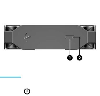
Front
Item |
Icon |
Component |
|
|
|
1 |
|
Power button |
|
|
|
2 |
|
Power on LED |
|
|
|
2Chapter 1 Hardware overview
Left
Item |
Icon |
Component |
|
|
|
1 |
|
USB 3.0 port |
|
|
|
2 |
|
USB 3.0 charging port |
|
|
|
3 |
|
Audio-out (headphone)/Audio-in (microphone) combo jack |
|
|
|
Left 3
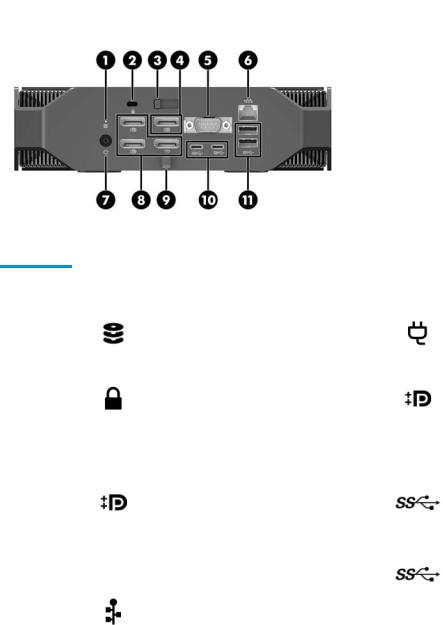
Rear
Performance model
Item |
Icon |
Component |
Item |
Icon |
Component |
|
|
|
|
|
|
|
|
Hard drive activity light |
|
|
|
1 |
|
On: The computer is on. |
7 |
|
Power cord connector |
|
|
|
|||
|
|
Blinking white: The hard drive is |
|
|
|
|
|
being accessed. |
|
|
|
|
|
|
|
|
|
2 |
|
Cable lock slot |
8 |
|
DisplayPort 1.2 connectors (3) |
|
|
Driven by NVIDIA GPU |
|||
|
|
|
|
|
|
|
|
|
|
|
|
3 |
|
Access panel release latch |
9 |
|
DC-IN cable clip |
|
|
|
|
|
|
|
|
DisplayPort 1.2 connector |
|
|
|
|
|
Driven by NVIDIA® or Intel® |
|
|
|
4 |
|
GPU. |
10 |
|
USB Type-C ports (2) |
|
|
|
|||
|
|
NVIDIA® is the default GPU. |
|
|
|
|
|
Intel® GPU can be selected in |
|
|
|
|
|
the BIOS (F10) menu. |
|
|
|
|
|
|
|
|
|
5 |
|
Serial port (optional) |
11 |
|
USB 3.0 ports (2) |
|
|
|
|
|
|
6 |
|
RJ-45 (network) jack |
|
|
|
|
|
|
|
|
|
4Chapter 1 Hardware overview
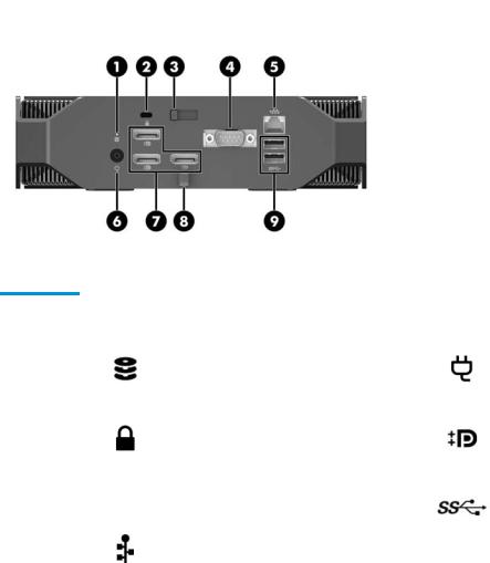
Entry model
Item |
Icon |
Component |
Item |
Icon |
Component |
|
|
|
|
|
|
|
|
Hard drive activity light |
|
|
|
1 |
|
On: The computer is on. |
6 |
|
Power cord connector |
|
|
|
|||
|
|
Blinking white: The hard drive is |
|
|
|
|
|
being accessed. |
|
|
|
|
|
|
|
|
|
2 |
|
Cable lock slot |
7 |
|
DisplayPort connectors (3) |
|
|
|
|
|
|
3 |
|
Access panel release latch |
8 |
|
DC-IN cable clip |
|
|
|
|
|
|
4 |
|
Serial port (optional) |
9 |
|
USB 3.0 ports (2) |
|
|
|
|
|
|
5 |
|
RJ-45 (network) jack |
|
|
|
|
|
|
|
|
|
Rear 5
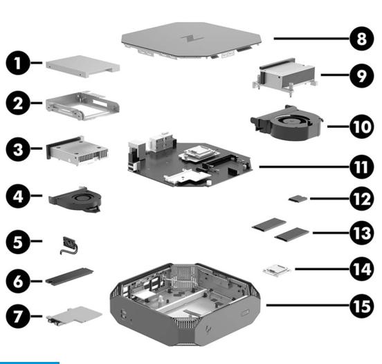
Chassis components
Component |
Description |
Component |
Description |
|
|
|
|
1 |
Hard drive, 2.5 inch |
9 |
Processor (CPU) heat sink |
|
|
|
|
2 |
Drive cage |
10 |
Processor fan |
|
|
|
|
3 |
Graphics heat sink (Performance models only) |
11 |
System board |
|
|
|
|
4 |
Graphics card fan (Performance models only) |
12 |
WLAN module |
|
|
|
|
5 |
Speaker |
13 |
Memory modules (SODIMMs) |
|
|
|
|
6 |
M.2 solid-state drive |
14 |
Processor |
|
|
|
|
7 |
M.2 heat sink |
15 |
Chassis |
|
|
|
|
8 |
Top cover |
|
|
|
|
|
|
6Chapter 1 Hardware overview
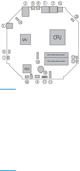
System board components
The following gures and tables describe the system board component layout.
Performance models
Component |
Description |
Component |
Description |
|
|
|
|
|
I/O |
|
Cooling |
|
|
|
|
1 |
DisplayPorts 3 and 4* |
12 |
CPU fan |
|
|
|
|
2 |
DisplayPorts 1 and 2* |
13 |
GPU fan |
|
|
|
|
3 |
Network/rear USB 3.0 |
14 |
Thermal sensor |
|
|
|
|
4 |
Serial (optional) |
|
Power |
|
|
|
|
5 |
Side USB 3.0 |
15 |
DC in |
|
|
|
|
6 |
Side audio |
16 |
SATA signal/power |
|
|
|
|
7 |
Speaker |
17 |
Clear CMOS jumper |
|
|
|
|
8 |
USB Type-C |
18 |
Battery |
|
|
|
|
9 |
USB Type-C |
|
Service |
|
|
|
|
|
M.2 |
19 |
Password jumper |
|
|
|
|
10 |
M.2 2280 Storage |
20 |
Power button/light (front) and hard drive light (rear) |
|
|
|
|
11 |
M.2 2230 WLAN |
|
|
*Ports 1–3: Nvidia only
*Port 4: Nvidia or Intel
System board components |
7 |
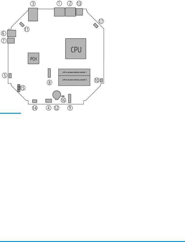
Entry models
Component |
Description |
Component |
Description |
|
|
|
|
|
I/O |
|
Cooling |
|
|
|
|
1 |
DisplayPort 3 |
10 |
CPU fan |
|
|
|
|
2 |
DisplayPorts 1 and 2 |
11 |
Thermal sensor |
|
|
|
|
3 |
Network/rear USB 3.0 |
|
Power |
|
|
|
|
4 |
Serial (optional) |
12 |
Battery |
|
|
|
|
5 |
Speaker |
13 |
DC in |
|
|
|
|
6 |
Side USB 3.0 |
14 |
SATA signal/power |
|
|
|
|
7 |
Side audio |
|
Service |
|
|
|
|
|
M.2 |
15 |
Clear CMOS jumper |
|
|
|
|
8 |
M.2 2280 storage |
16 |
Password jumper |
|
|
|
|
9 |
M.2 2230 WLAN |
17 |
Power button/light (front) and hard drive light (rear) |
|
|
|
|
Diagnostic light and audible codes
Provide diagnostic information through the front panel light (blinks) and system speaker (beeps). the codes are in major/minor format – major are red blinks with long, low pitch beeps; minor are white blinks with short, high-pitch beeps.
Major.minor |
2.x |
3.2 |
3.3 |
3.4 |
3.5 |
3.6 |
4.x |
5.x |
|
|
|
|
|
|
|
|
|
Diagnosis |
BIOS |
Memory |
Graphics |
Power supply |
CPU |
CPU |
Thermal |
System board |
|
|
|
|
|
|
|
|
|
8Chapter 1 Hardware overview

System board architecture
The following gures show the system board block diagram.
System board architecture |
9 |
Computer sp |
t ons |
|
|
|||
Physical characteristics and technical sp |
t ons |
|||||
|
|
|
|
|
|
|
|
|
|
|
HP Z2 Mini G3 Workstation |
||
|
|
|
|
|
|
|
|
Weight (not including external |
Unit only (Performance) |
2.08 kg (4.58 lbs) |
|||
|
|
|
|
|
||
|
power supply) |
|
Unit only (Entry) |
1.87 kg (4.12 lbs) |
||
|
|
|
||||
|
|
|
|
|
||
|
|
|
Unit only |
Height: 58 mm (2.3 in) |
||
|
Dimensions |
|
|
|
Width: 216 mm (8.5 in) |
|
|
|
|
|
|
||
|
|
|
|
|
Depth: 216 mm (8.5 in) |
|
|
|
|
|
|
|
|
|
|
|
Intel® Series C236 chipset with: |
|
|
|
|
|
|
● Support for 5th generation Intel® Xeon® processors (80 W)(Performance and Entry models) |
|||
|
|
|
|
or 6th generation Intel Core™ processors (65W) (Entry models) |
||
|
Processor technology |
|
● |
Integrated 2-channel memory controller |
||
|
|
|
|
|
|
|
|
|
|
● Integrated graphics (some models) |
|||
|
|
|
● Advanced Vector Extensions (AVX) to increase floating point performance |
|||
|
|
|
● Intel DMI3 interface connecting the processor to the I/O controller |
|||
|
|
|
|
|||
|
|
|
● (Performance models) 200 W external or (Entry models) 135 W external, DoE VI efficient, |
|||
|
Power supply |
|
|
compatible with ENERGY STAR® Version 6.1 requirements |
||
|
|
|
|
|
|
|
|
|
|
● |
Supports European Union ERP Lot 6 tier 2 power limit of less than 0.5 W in o mode |
||
|
|
|
|
|||
|
|
|
● Dual inline memory modules (SODIMMs) based on DDR4 2400 MHz technology |
|||
|
|
|
● Supports error checking and correcting (ECC) and non-ECC SODIMMs |
|||
|
|
|
● Two direct-attach memory channels that enable low-latency access and fast data transfer |
|||
|
|
|
|
for improved performance |
|
|
|
Memory technology |
|
● |
Up to 32 GB system memory (2 x 16 GB SODIMMs) |
||
|
|
|
||||
|
|
|
● |
(Performance models) 2133 MHz, 8 GB, or 16 GB non-ECC unbu ered SODIMM |
||
|
|
|
● |
(Entry models) 2133 MHz, 4 GB, 8 GB, or 16 GB ECC unbu ered SODIMM |
||
|
|
|
NOTE: The processor may limit the speed of the memory. Some processors may run the |
|||
|
|
|
memory at less than the rated speed of the SODIMMs. Check your speci c processor |
|||
|
|
|
speci |
cations. |
|
|
|
|
|
|
|||
|
|
|
● NVIDIA Quadro M620, 2 GB (discrete, embedded)(Performance models) |
|||
|
|
|
|
NOTE: NVIDIA Quadro M620 graphics can drive up to 4 displays simultaneously. |
||
|
Graphics |
|
● |
Supports Intel HD Graphics 510 or Intel HD Graphics 530 (Core processors) or Intel HD |
||
|
|
|
Graphics P530 (Xeon processors) |
|||
|
|
|
|
|||
|
|
|
|
NOTE: In Performance models, Intel HD Graphics is disabled by default. |
||
|
|
|
|
NOTE: Intel HD graphics can drive up to 3 displays simultaneously. |
||
|
|
|
|
|
|
|
|
|
|
Performance models |
|
|
|
|
|
|
● (4) USB 3.0 ports |
|
|
|
|
I/O technology |
|
● |
(4) DisplayPort 1.2 |
|
|
|
|
|
● (2) Type-C USB 3.1 Gen1 |
|
|
|
|
|
|
● RJ-45 for LAN |
|
|
|
10 Chapter 1 Hardware overview

|
|
HP Z2 Mini G3 Workstation |
|
|
|
|
● |
Headphone/microphone combination jack |
|
● WLAN and Bluetooth module (optional) |
|
|
● |
Supports European Union ERP Lot 6 tier2 power limit of less than 0.5W in o mode |
|
Entry models |
|
|
● |
(3) DisplayPort 1.2 |
|
● |
(4) USB 3.0 |
|
● RJ-45 for LAN |
|
|
● |
Headphone/microphone combination jack |
|
● WLAN and Bluetooth module (optional) |
|
|
|
|
|
● (1) 2.5-inch SATA hard drive or solid-state drive, 9.5 mm max height |
|
Storage devices |
● |
(1) M.2 2280 Z Turbo Drive |
|
● Up to 2 TB max storage |
|
|
|
|
Environmental sp |
t ons |
|||
|
|
|
|
|
|
Item |
Value |
|
|
|
|
|
||
|
|
Operating: 5°C to 35°C (40°F to 95°F) |
||
|
|
Nonoperating: -40°C to 60°C (-40°F to 140°F) |
||
|
Temperature |
NOTE: The ambient upper limit of 35°C is good up to 1524 m (5000 ft) elevation. Derate by 1°C for |
||
|
|
|||
|
|
every 305 m (1000 ft) above 1524 m (5000 ft). For example, at 3,048 m (10,000 ft), the upper |
||
|
|
ambient air temperature limit is 30°C. |
||
|
|
|
||
|
Humidity |
Operating: 8% to 85% relative humidity, non-condensing |
||
|
Nonoperating: 8% to 90% relative humidity, non-condensing |
|||
|
|
|||
|
|
|
||
|
Altitude |
Operating: 0 to 3,048 m (10,000 ft) |
||
|
Nonoperating: 0 to 9,144 m (30,000 ft) |
|||
|
|
|||
|
|
|
||
|
|
Operating: ½-sine: 40g, 2–3 ms (~62 cm/sec) |
||
|
|
Nonoperating: |
||
|
Shock |
● |
½-sine: 160 cm/s, 2–3 ms (~105g) |
|
|
|
● |
square: 422 cm/s, 20g |
|
|
|
NOTE: |
Values represent individual shock events and do not indicate repetitive shock events. |
|
|
|
|
||
|
|
Operating random: 0.5g (rms), 5–300 Hz, up to 0.0025 g2/Hz |
||
|
Vibration |
Non-operating random: 2.0g (rms), 5–500 Hz, up to 0.0150 g2/Hz |
||
|
|
NOTE: |
Values do not indicate continuous vibration. |
|
|
|
|
|
|
Computer speci cations 11
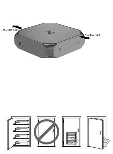
Ensuring proper ventilation
Proper ventilation for the system is important for computer operation. To be sure that there is adequate ventilation:
●Operate the computer on a sturdy, level surface.
●Provide at least 15.24 cm (6.00 in) of clearance at the front and back of the computer. (This is the minimum distance for all computer models.)
●Be sure that the ambient air temperature surrounding the computer falls within the speci ed limits (see Environmental speci cations on page 11).
●For cabinet installation, ensure adequate cabinet ventilation and ensure that the ambient temperature within the cabinet does not exceed speci ed limits.
●Never restrict the incoming or outgoing airflow of the computer by blocking any vents or air intakes.
12 Chapter 1 Hardware overview
2System management
This section describes the tools and utilities that provide system management for the computer.
Topics
Adding monitors on page 14
Power management features on page 17
BIOS ROM on page 18
Computer Setup (F10) Utilities on page 18
Desktop management on page 29
13
Adding monitors
Planning for additional monitors
Entry model
The HP Z2 Mini G3 Entry system supports up to three simultaneous displays running on the Intel integrated GPU. Each display is capable of resolutions up to 4096 × 2160 @ 60 Hz.
It is also possible to drive a panel at a resolution of 5120 × 2880 @60 Hz by using two of the DisplayPort 1.2 outputs together. The panel must support this method of achieving this resolution for this to be possible.
Performance model
The HP Z2 Mini G3 Performance model is capable of operating in two distinct modes: NVIDIA GPU–only mode or NVIDIA GPU + Intel GPU mode. The NVIDIA GPU–only mode o ers the best performance, while the NVIDIA GPU + Intel GPU mode allows the system to drive an additional two displays.
NVIDIA GPU–only mode:
●The default con guration.
●O ers the best performance because every DisplayPort 1.2 port is driven directly by the NVIDIA Quadro GPU.
●Capable of driving up to four independent displays at a maximum resolution of 4096×2160 @ 60 Hz or two independent displays at a maximum resolution of 5120×2880 @ 60 Hz by combining DisplayPort outputs. The display must support this method of achieving this resolution.
NVIDIA GPU + Intel GPU mode:
●The NVIDIA GPU can support a maximum of four independent displays. To support an additional two displays, the system can be con gured to simultaneously use both the NVIDIA Quadro GPU and the Intel integrated GPU.
●This mode is con gured in the system BIOS.
1.Press the power button on the system, and then repeatedly press the F10 key until you’ve reached the system BIOS GUI.
2.Navigate to the Advanced tab.
3.Select Built-In Device Options.
4.Select Enable Intel graphics on DisplayPort port #4.
5.Press Enter to accept the prompt notifying you that the Intel GPU will be output on DisplayPort #4.
6.Press F10 to save your changes and exit.
●This mode is capable of driving up to six independent displays.
— Because the system has only four DisplayPort 1.2 ports, two of the DisplayPort 1.2 ports must each drive two displays in a daisy-chained con guration. This is accomplished by using DisplayPort
14 Chapter 2 System management

1.2 Multi-Stream Transport (MST) and requires displays which support MST or DisplayPort hubs capable of MST.
—To achieve a six-display con guration, one of the daisy chains must be driven by the Intel GPU on DisplayPort #4. Refer to Performance model on page 4 to identify speci c DisplayPorts. The other daisy chain can be driven by the NVIDIA Quadro GPU on any of the remaining DisplayPort 1.2 ports.
—Each DisplayPort 1.2 output on the system is capable of driving a display at a resolution of 4096 × 2160 @ 60 Hz. When two displays are daisy-chained together from a single DisplayPort 1.2 port, each display in the daisy chain is bandwidth-limited to a maximum resolution of 2560 × 1600 @ 60 Hz.
●Performance is dependent upon which GPU is running the application. For the best performance of a particular application, ensure that the application is running on the NVIDIA Quadro GPU.
Planning process
The process for adding monitors depends on the type and number of monitors you add.
Use the following process to plan for adding more monitors:
1.Assess your monitor needs.
a.Determine how many monitors you require.
b.Determine the kind of graphics performance you want. For maximum performance, ensure that your display is driven by the NVIDIA Quadro GPU.
c.Note the type of graphics connector used by each monitor. HP provides graphics cards with DisplayPort (DP) and DVI interfaces, but you can use adapters and third-party cards for other graphics formats, including DVI-I, HDMI, or VGA.
TIP: Some adapters for older legacy hardware may cost more than others. You may want to compare the cost of acquiring adapters with the cost of getting a newer monitor that doesn't need adapters.
2.Install drivers and con gure resolutions.
a.Be sure that you have the correct drivers for the card. See http://www.hp.com for HP-quali ed drivers.
b.Con gure each monitor’s resolution, orientation, and placement through Windows Display Settings. For details, refer to Windows Help or to http://www.microsoft.com.
c.For monitor setup in Linux, you can often use the settings tool for the graphics cards (e.g., NVIDIA® nvidia-settings). In some recent Linux releases, the window manager system (e.g., Gnome 3)
preferences must also be modi ed.
TIP: To simplify troubleshooting of possible problems, enable the monitors one at a time: enable the rst monitor and be sure that it works properly before enabling the next monitor.
Adding monitors 15

Matching graphics card connector to monitor connectors
The following table describes monitor con guration scenarios.
Graphics card interface connector |
|
|
Monitor connector |
|
|
|
|
|
|
|
|
|
|
|
VGA |
DVI |
|
Dual Link DVI |
DisplayPort |
HDMI |
|
|
(DP) |
||||
|
|
|
|
|
|
|
|
|
|
|
|
|
|
DISPLAYPORT |
DisplayPort to |
|
|
|
|
|
|
VGA adapter |
DP to DVI |
|
DP to DL DVI |
DP cable |
DP to HDMI |
|
|
|
||||
|
(sold |
adapter |
|
adapter |
adapter |
|
|
|
|
||||
|
|
|
|
|
|
|
|
separately) |
|
|
|
|
|
|
|
|
|
|
|
|
 NOTE: DisplayPort connections have the highest performance; VGA connections have the lowest.
Identifying monitor connection requirements
Graphics card with DisplayPort output —The system has four DisplayPort 1.2 outputs. You can connect a monitor to each connector. Use the proper adapters, if required.
Connecting and on ur n monitors
1.Connect the monitor cable adapters (if required) to the computer, then connect the appropriate monitor cables to the adapters or directly to the graphics card.
2.Connect the other ends of the monitor cables to the monitors.
3.Connect one end of the monitor power cord to the monitor and the other end to an AC outlet.
4.Con gure the monitor. For details, refer to Microsoft Help or to http://www.microsoft.com.
For monitor setup in Linux, you can often use the settings tool for the graphics cards (e.g., NVIDIA nvidia-settings or AMD Catalyst Control Center). In some recent Linux releases, the window manager system (e.g., Gnome 3) preferences must also be modi ed.
16 Chapter 2 System management

Customizing the monitor display (Windows)
You can manually select or change the monitor model, refresh rates, screen resolution, color settings, font sizes, and power management settings.
●To change display settings for Windows 10, type control panel in the taskbar search box, and then select Control Panel. Select Appearance and Personalization, then Display.
●To change display settings in Windows 7, right-click a blank area on the desktop, and then click Screen Resolution.
For more information about customizing your monitor display, see the following resources:
●Online documentation provided with the graphics controller utility
●Documentation included with your monitor
Power management features
ERP compliance mode
This computer provides ERP compliance mode capability.
When this feature is enabled, the computer shuts down to the lowest possible power state.
When this feature is disabled, the computer shuts down conventionally.
Item |
Description |
||
|
|
|
|
|
1. |
Power on or restart the computer and press F10 during startup to launch the Computer Setup (F10) utility. |
|
|
2. |
Disable Wake-on LAN. |
|
Enabling ERP |
3. |
Using the arrow keys, select Advanced, and then Power Management Options. |
|
4. |
Select S5 Maximum Power Savings. |
||
compliance |
|||
mode |
5. |
Select Exit, and then select Save Changes and Exit. |
|
|
|||
|
6. |
If using Windows 10, boot to Windows and search in the Start Menu for the setting Change what the power |
|
|
|
buttons do. Uncheck Turn on fast startup (recommended). If the checkbox is not available, select Change |
|
|
|
settings that are currently unavailable at the top of the window. |
|
|
|
|
|
|
1. |
Power on or restart the computer and press F10 during startup to launch the Computer Setup (F10) utility. |
|
|
2. |
Enable Wake-on LAN. |
|
Disabling ERP |
3. |
Using the arrow keys, select Advanced, and then Power Management Options. |
|
4. |
Disable S5 Maximum Power Savings. |
||
compliance |
|||
mode |
5. |
Select Exit, and then select Save Changes and Exit. |
|
|
|||
|
6. |
If using Windows 10, boot to Windows and search in the Start Menu for the setting Change what the power |
|
|
|
buttons do. Check Turn on fast startup (recommended). If the check box is not available, select Change |
|
|
|
settings that are currently unavailable at the top of the window. |
|
|
|
|
|
Power management features 17
Hyper-Threading Technology (HTT)
This computer supports HTT, an Intel-proprietary technology that improves processor performance through parallelization of computations (doing multiple tasks at once).
The operating system treats an HTT-enabled processor as two virtual processors and shares the workload between them when possible. This feature requires that the operating system support multiple processors and be speci cally optimized for HTT.
Use the Computer Setup (F10) Utility to enable HTT.
Go to http://www.hp.com/go/quickspecs to determine if your CPU supports HTT.
SATA Power Management
SATA Power Management enables or disables SATA bus and/or device power management.
Intel Turbo Boost Technology
The HP Z Workstation series supports Intel® Turbo Boost Technology.
This feature enables the CPU to run at frequencies above the normal frequency. When all CPU cores are not necessary for the workload, inactive cores are turned o and power is diverted to the active cores to increase their performance.
Turbo Boost is enabled and disabled with the Computer Setup (F10) Utility.
Go to http://www.hp.com/go/quickspecs to determine if your CPU supports Turbo Boost.
BIOS ROM
The BIOS ROM is a collection of machine language applications stored as rmware in ROM. It includes functions such as Power-On Self-Test (POST), PCI device initialization, Plug and Play support, power management, and Computer Setup (F10) Utility.
Go to http://www.hp.com/go/quickspecs to review the latest BIOS ROM speci cations.
Computer Setup (F10) Utilities
Use Computer Setup (F10) Utility to do the following:
●Change settings from the defaults or restore the settings to default values.
●View the system con guration, including settings for processor, graphics, memory, audio, storage, communications, and input devices.
●Modify the boot order of bootable devices such as hard drives, optical drives, or USB flash media devices.
●Establish an Ownership Tag, the text of which is displayed each time the system is turned on or restarted.
●Enter the Asset Tag or property identi cation number assigned by the company to this computer.
●Enable the power-on password prompt during system restarts (warm boots) as well as during power-on.
●Establish an administrator password that controls access to the Computer Setup (F10) Utility and the settings described in this section.
●Establish minimum requirements for valid passwords, including length and required types of characters.
18 Chapter 2 System management

●Secure integrated I/O functionality, including the serial, USB, or audio, or embedded NIC, so that they cannot be used until they are unsecured.
●Enable or disable di erent types of boot sources.
●Con gure features such as Secure Boot, power management, virtualization support, and language and keyboard type used in Setup and POST.
●Replicate the system setup by saving system con guration information on a USB device and restoring it on one or more computers.
●Enable or disable DriveLock security or securely erase a hard drive (when supported by drive).
Using Computer Setup (F10) Utilities
Computer Setup can be accessed only by turning the computer on or restarting the system. To access the Computer Setup Utilities menu, complete the following steps:
1.Turn on or restart the computer.
2.Repeatedly press F10 when the monitor light turns on to access the utility.
You can also press Esc to a menu that allows you to access di erent options available at startup, including the Computer Setup utility.
 NOTE: If you do not press F10 at the appropriate time, you must restart the computer and again repeatedly press F10 when the monitor light turns green to access the utility.
3.A choice of four headings appears in the Computer Setup Utilities menu: Main, Security, Advanced, and UEFI Drivers.
 NOTE: Selecting UEFI Drivers restarts the computer into the 3rd party option ROM management application. You can access this application directly by pressing F3 during startup.
4.Use the arrow (left and right) keys to select the appropriate heading. Use the arrow (up and down) keys to select the option you want, then press Enter. To return to the Computer Setup Utilities menu, press Esc.
5.To apply and save changes, select Main > Save Changes and Exit.
●If you have made changes that you do not want applied, select Ignore Changes and Exit.
●To restore settings from the Advanced and Main menus to original values, select Apply Factory Defaults and Exit.
●To restore settings from the Advanced and Main menus to those previously saved by Save Custom Defaults, select Apply Custom Defaults and Exit. If no custom defaults have been saved, then factory defaults are used.
 NOTE: Settings in the Security menu are not modi ed by Apply Defaults. Those values are reset by
Restore Security Settings to Factory Defaults at the bottom of the Security menu.
 NOTE: Not all settings shown in the following sections are available for all models
 CAUTION: Do NOT turn the computer power OFF while the BIOS is saving the Computer Setup (F10) changes because the settings could become corrupted. It is safe to turn o the computer only after exiting the F10 Setup screen.
Computer Setup (F10) Utilities 19

Computer Setup–Main
 NOTE: Support for speci c Computer Setup options may vary depending on the hardware con guration.
Table 2-1 Computer Setup—Main
Option |
Description |
|
|
|
|
System Information |
Lists all information in following list if Advanced System Information is selected. Lists smaller subset if |
|
|
Basic System Information is selected. |
|
|
● |
Product name |
|
● |
Memory size |
|
● |
Processor type |
|
● |
Processor cache size (L1/L2/L3) |
|
● |
Processor speed |
|
● |
MicroCode Revision |
|
● |
Processor Stepping |
|
● |
Memory Speed |
|
● |
SODIMM size (for each installed module) |
|
● |
System BIOS version |
|
● |
ME Firmware version |
|
● |
Primary Video BIOS version |
|
● |
Super I/O Firmware version |
|
● |
Serial Number |
|
● |
SKU number |
|
● |
UUID (Universally Unique Identi er) |
|
● |
Asset Tracking Number |
|
● |
Feature Byte |
|
● |
Build ID |
|
● |
Product Family |
|
● |
System Board ID |
|
● |
System Board CT |
|
● |
Integrated MAC Address |
|
|
|
System Diagnostics |
If the hard drive has the HP Advanced Diagnostics installed, the application will launch. If HP Advanced |
|
|
Diagnostics is not installed, then a basic version built into the BIOS will provide the capability to perform |
|
|
the following functions: |
|
|
● |
Memory Test |
|
● |
Hard Drive Check |
|
● |
Language |
|
|
|
Update System BIOS |
Lets you update the system BIOS from www.hp.com or another network server, from a removable USB |
|
|
drive, or from a le located on the hard drive. |
|
|
● |
‘Check HP.com for BIOS Updates’ or ‘Check the Network for BIOS Updates’ |
|
|
The string that appears here depends on the setting in ‘BIOS Update Preferences’. |
20 Chapter 2 System management

Table 2-1 Computer Setup—Main (continued)
Option |
Description |
||
|
|
|
|
|
● |
Lock BIOS Version |
|
|
|
If this option is checked, the system is locked to the current BIOS version and updates are not |
|
|
|
allowed. |
|
|
● |
BIOS Update Preferences |
|
|
|
Allows the administrator to select the source of network updates (www.hp.com or another network |
|
|
|
server) and allows con guration of a periodic check for updates, including policies for: |
|
|
|
■ |
Check for updates and prompt the user to accept or reject the update at that time |
|
|
■ |
Check for updates and install all new versions |
|
|
■ |
Check for updates and install only new versions marked important |
|
● |
Network Con guration Settings |
|
|
● |
Update BIOS Using Local Media |
|
|
|
Lets you access les on either USB storage or the hard drive. The HP BIOS Update and Recovery |
|
|
|
application included in BIOS Softpaqs at www.hp.com will copy the BIOS le to the correct location |
|
|
|
on the hard drive or USB device. |
|
|
|
||
System IDs |
Lets you set the following values: |
||
|
● |
Asset Tracking Number |
|
|
● |
Ownership Tag |
|
|
● |
Change Date & Time |
|
|
● |
Set Machine Unique Data |
|
|
|
||
Replicated Setup |
Backup current settings to USB device |
||
|
Saves system con guration to a formatted USB flash media device. |
||
|
Restore current settings from USB device |
||
|
Restores system con guration from a USB flash media device. |
||
|
|
||
Save Custom Defaults |
Saves the current system con guration settings as the custom default set. |
||
|
|
||
Apply Custom Defaults |
Applies the custom default settings to the computer after rebooting. Does not apply to options in the |
||
and Exit |
Security menu. |
||
|
|
||
Apply Factory Defaults |
Restores the factory system con guration settings to the computer after rebooting. Does not apply to |
||
and Exit |
options in the Security menu. |
||
|
|
||
Ignore Changes and Exit |
Exits Computer Setup without applying or saving any changes. |
||
|
|
||
Save Changes and Exit |
Saves changes to current system con guration, exits Computer Setup, and reboots. |
||
|
|
|
|
Computer Setup (F10) Utilities 21
Loading...