


 Loading...
Maintenance and Service
Guide
HP xb3000 Notebook Expansion Base
Document Part Number: 416285-001
July 2006
This guide is a troubleshooting reference used for maintaining a nd servicing the HP xb3000 Notebook Expansion Base. It provides comprehensive information on identifying expansion base features, components, and spare parts; troubleshooting problems; and performing disassembly procedures.
© Copyright 2006 Hewlett-Packard Development Company, L.P.
The information contained herein is subject to change without notice. The only warranties for HP products and services are set forth in the express warranty statements accompanying such products and services. Nothing herein should be construed as constituting an additional warranty. HP shall not be liable for technical or editorial errors or omissions contained herein.
Maintenance and Service Guide
HP xb3000 Notebook Expansion Base
First Edition: July 2006
Document Part Number: 416285-001

Contents
1 Product Description
1.1 Features . . . . . . . . . . . . . . . . . . . . . . . . . . . . . . . . . . . 1–3
1.2 External Components . . . . . . . . . . . . . . . . . . . . . . . . 1–4
1.3 Wireless Accessories. . . . . . . . . . . . . . . . . . . . . . . . 1–10
1.4 Design Overview. . . . . . . . . . . . . . . . . . . . . . . . . . . 1–11
1.5 Using the Expansion Base. . . . . . . . . . . . . . . . . . . . 1–12
1.6 Using the HP Expansion Accessory Adapter . . . . . 1–20
1.7 Synchronizing Wireless Devices. . . . . . . . . . . . . . . 1–23
2 Troubleshooting
2.1 Before Replacing Parts . . . . . . . . . . . . . . . . . . . . . . . 2–1
2.2 Problems and Solutions. . . . . . . . . . . . . . . . . . . . . . . 2–2
Maintenance and Service Guide |
iii |

Contents
3 Illustrated Parts Catalog
3.1 Serial Number Location . . . . . . . . . . . . . . . . . . . . . . 3–1 3.2 Expansion Base Major Components . . . . . . . . . . . . . 3–2 3.3 Wireless Components . . . . . . . . . . . . . . . . . . . . . . . . 3–4 3.4 Hard Drive Components . . . . . . . . . . . . . . . . . . . . . . 3–5 3.5 Sequential Part Number Listing . . . . . . . . . . . . . . . . 3–6
4 Removal and Replacement Preliminaries
4.1 Tools Required . . . . . . . . . . . . . . . . . . . . . . . . . . . . . 4–1 4.2 Service Considerations . . . . . . . . . . . . . . . . . . . . . . . 4–2 4.3 Preventing Damage to Removable Drives . . . . . . . . 4–3 4.4 Preventing Electrostatic Damage . . . . . . . . . . . . . . . 4–4 4.5 Packaging and Transporting Precautions . . . . . . . . . 4–5 4.6 Workstation Precautions . . . . . . . . . . . . . . . . . . . . . . 4–6 4.7 Grounding Equipment and Methods . . . . . . . . . . . . . 4–7
iv |
Maintenance and Service Guide |

Contents
5 Removal and Replacement Procedures
5.1 Serial Number . . . . . . . . . . . . . . . . . . . . . . . . . . . . . . 5–2 5.2 Disassembly Sequence Chart . . . . . . . . . . . . . . . . . . 5–3 5.3 Preparing the Expansion Base for Disassembly . . . . 5–3 5.4 Installing an Optional Hard Drive. . . . . . . . . . . . . . . 5–4
6 Specifications
AScrew Listing
BConnector Pin Assignments
CPower Cord Set Requirements Index
Maintenance and Service Guide |
v |
1
Product Description
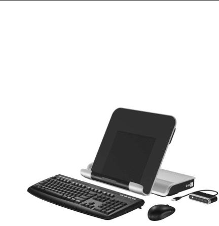
The HP xb3000 Notebook Expansion Base provides an efficient, less-cluttered work environment, improved cable management, and wireless peripherals. It eliminates the need to purchase a separate monitor, external speakers, USB hub, and a wireless keyboard and mouse kit.
HP xb3000 Notebook Expansion Base with Wireless Components
Maintenance and Service Guide |
1–1 |

Product Description
The HP xb3000 Notebook Expansion Base is compatible with the following platforms:
■HP Pavilion dv9000 Notebook PC
■HP Pavilion dv6000 Notebook PC
■HP Pavilion dv2000 Notebook PC
■HP Pavilion tx1000 Entertainment PC
■Compaq Presario V6000 Notebook PC
■Compaq Presario V3000 Notebook PC
The following computers require use of the HP Expansion Accessory Adapter to connect to the expansion base:
■HP Pavilion dv8300 Notebook PC
■HP Pavilion dv8000 Notebook PC
■HP Pavilion dv5000 Notebook PC
■HP Pavilion dv4000 Notebook PC
■HP Pavilion dv1400 Entertainment Notebook PC
■HP Pavilion ze2000Notebook PC
■HP Compaq nx4820 Notebook PC
■HP Special Edition L2000 Notebook PC
■Compaq Presario V5000 Notebook PC
■Compaq Presario V4000 Notebook PC
■Compaq Presario V2000 Notebook PC
■Compaq Presario M2000 Notebook PC
1–2 |
Maintenance and Service Guide |

Product Description
1.1Features
Adjustable height
External AC adapter (charges docked computer)
Support for display panel sizes up to 43 cm (17 inches) wide
Altec/Lansing ported speakers
Wireless keyboard, mouse, receiver
Hard drive bay and power connector
Security slots (2)
Infrared pass-through support
Lights (power, good dock, mute)
Volume control wheel with mute button
Connectors:
Expansion cable
Audio-out (headphone) connector
Audio-in (microphone) connector
Universal Serial Bus (USB) 2.0 connectors (6)
Power connector
Component video jacks
S-Video-out
Composite video jack
S/PDIF (Sony/Philips Digital Interface) audio connector
External monitor port
RJ-45/Ethernet port
Hard drive power connector
Maintenance and Service Guide |
1–3 |
Product Description
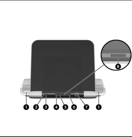
1.2 External Components
The external components on the front panel of the expansion base are shown below and described in Table 1-1.
Front Components
|
|
Table 1-1 |
|
|
Front Components |
|
|
|
Item |
Component |
Function |
|
|
|
1 |
Speakers (2) |
Produce stereo expansion base sound. |
|
|
|
2 |
Power button |
Turns on the computer. |
|
|
|
1–4 |
Maintenance and Service Guide |

Product Description
Table 1-1
Front Components (Continued)
Item |
Component |
Function |
|
|
|
3 |
Power light |
On: The expansion base is connected to |
|
|
AC power. |
|
|
|
4 |
Mute button |
Mutes and restores expansion base sound. |
|
|
|
5 |
Volume down button |
Blinking: The volume scroll zone is being |
|
|
used to decrease expansion base sound. |
|
|
|
6 |
Volume up button |
Blinking: The volume scroll zone is being |
|
|
used to increase expansion base sound. |
|
|
|
7 |
Consumer infrared |
Detects the computer remote control |
|
lens |
infrared signal. |
|
|
|
8 |
Volume scroll zone |
Adjusts volume. Slide your finger to the left |
|
|
to decrease volume and to the right to |
|
|
increase volume. |
■ To decrease volume, slide your finger to the left, tap the left half of the scroll zone, or hold your finger over the left half of the scroll zone.
■ To increase volume, slide your finger to the right, tap the right half of the scroll zone, or hold your finger over the right half of the scroll zone.
Maintenance and Service Guide |
1–5 |
Product Description
The external components on the right side of the expansion base are shown below and described in Table 1-2.
Right-Side Components
Table 1-2
Right-Side Components
Item |
Component |
Function |
|
|
|
1 |
Audio-out |
Produces expansion base sound when |
|
(headphone) jack |
connected to optional powered stereo |
|
|
speakers, headphones, ear buds, a |
|
|
headset, or television audio. |
|
|
|
2 |
Audio-in (microphone) |
Connects an optional computer headset |
|
jack |
microphone, stereo array microphone, or |
|
|
monaural microphone. |
|
|
The expansion base speakers are |
|
|
muted when a device is connected to |
|
|
the headphone jack. |
|
|
|
3 |
USB ports (2)* |
Connect optional USB devices. |
*There are 4 additional USB ports on the rear panel of the expansion base.
1–6 |
Maintenance and Service Guide |
Product Description
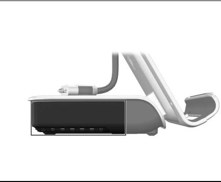
The external component on the left side of the expansion base is shown below and described in Table 1-3.
Left-Side Components
|
Table 1-3 |
|
Left-Side Component |
|
|
Component |
Function |
|
|
Hard drive bay |
Holds an optional internal hard drive. |
|
|
Maintenance and Service Guide |
1–7 |
Product Description
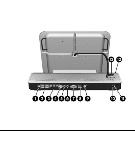
The expansion base rear panel components are shown below and described in Table 1-4.
Rear Panel Components
Table 1-4
Rear Panel Components
Item |
Component |
Function |
|
|
|
1 |
Power connector |
Connects the expansion base to the |
|
|
computer AC adapter. |
|
|
|
2 |
USB ports (4)* |
Connect optional USB devices. |
|
|
|
3 |
Component video jacks |
Connect an optional component video |
|
|
device. |
|
|
|
4 |
S-Video-out jack |
Connects an optional S-Video device such |
|
|
as a television, VCR, camcorder, |
|
|
overhead projector, or video capture card. |
|
|
|
1–8 |
Maintenance and Service Guide |

Product Description
Table 1-4
Rear Panel Components (Continued)
Item |
Component |
Function |
|
|
|
5 |
Composite video jack |
Connects an optional composite video |
|
|
device. |
|
|
|
6 |
S/PDIF (Sony/Philips |
Connects an optional compatible |
|
Digital Interface) digital |
audio/video receiver through a digital |
|
audio jack |
coaxial cable (purchased separately). |
|
|
|
7 |
External monitor port |
Connects an optional external VGA |
|
|
monitor or projector. |
|
|
|
8 |
RJ-45 (network) jack |
Connects an Ethernet cable from the |
|
|
expansion base to an RJ-45 wall jack. |
|
|
|
9 |
Hard drive power |
Connects the power cord for the optional |
|
connector |
internal hard drive. |
|
|
|
10 |
Security cable slot |
Attaches an optional security cable to the |
|
|
expansion base. |
|
|
The security cable is designed to |
|
|
act as a deterrent, but it may not |
|
|
prevent the expansion base from |
|
|
being mishandled or stolen. |
|
|
|
11 |
Hard drive carrier screw |
Secures the hard drive carrier for the |
|
|
optional internal hard drive. |
|
|
|
12 |
Expansion cable |
Connects the expansion base to a |
|
|
computer. |
|
|
|
13 |
Connection indicator |
On: The computer is connected correctly. |
|
light |
|
*There are 2 additional USB ports on the right side of the expansion base.
Maintenance and Service Guide |
1–9 |
Product Description
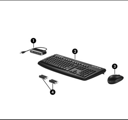
1.3 Wireless Accessories
The wireless components shown below and described in Table 1-5 are included with the expansion base.
Wireless Accessories
|
|
Table 1-5 |
|
Keyboard Components |
|
|
|
|
Item |
Component |
Function |
|
|
|
1 |
Receiver |
Connects to a USB port on the expansion |
|
|
base. Enables connection between the |
|
|
expansion base and the wireless keyboard |
|
|
and mouse. |
|
|
|
2 |
Wireless keyboard |
Connects to the expansion base without |
|
|
a cable. |
|
|
|
3 |
Wireless mouse |
Connects to the expansion base without |
|
|
a cable. |
|
|
|
4 |
Batteries |
To be inserted into the wireless keyboard |
|
|
and mouse. |
|
|
|
1–10 |
Maintenance and Service Guide |

Product Description
1.4 Design Overview
This section presents a design overview of key parts and features of the expansion base. Refer to Section , “Illustrated Parts Catalog,” to identify replacement parts, and Section , “Removal and Replacement Procedures,” for disassembly steps.
The expansion base provides the following device connections:
■Expansion cable
■S/PDIF (Sony/Philips Digital Interface) audio connector
■Audio-out (headphone) jack
■Composite out
■RJ-11 (modem) connection (from wall to expansion base)
■RJ-11 (modem) connection (from expansion base to computer)
■RJ-45 (network) port
■USB 2.0 connectors (3)
■S-Video-out
■Serial port
ÄCAUTION: To properly ventilate the expansion base, allow at least a 7.6-cm (3-inch) clearance on the left and right sides of the unit.
The computer uses an electric fan for ventilation. The fan is controlled by a temperature sensor and is designed to turn on automatically when high temperature conditions exist. These conditions are affected by high external temperatures, system power consumption, power management/battery conservation configurations, battery fast charging, and software.
Maintenance and Service Guide |
1–11 |
Product Description
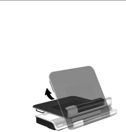
1.5 Using the Expansion Base
Adjusting the Expansion Base
The expansion base must be upright before a computer is attached.
To adjust the expansion base to an upright position:
»Lift the upper panel to the appropriate height.
Adjusting the Expansion Base
1–12 |
Maintenance and Service Guide |
Product Description
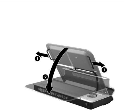
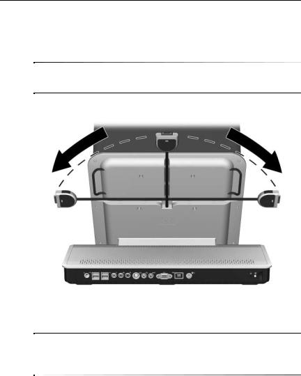
To lower the expansion base:
1.Pull out the handles on each side of the expansion base 1.
2.Grasp the handles and lower the upper panel of the expansion base 2.
Lowering the Expansion Base
Maintenance and Service Guide |
1–13 |

Product Description
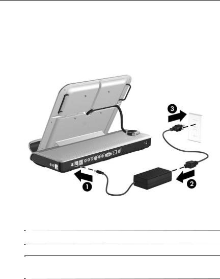
Connecting to AC Power
ÅWARNING: To reduce the risk of electric shock or damage to your equipment:
■Plug the power cord into an electrical outlet that is easily accessible at all times.
■Disconnect power from the product by unplugging the power cord from the electrical outlet.
■If provided with a 3-pin attachment plug on your power cord, plug the cord into a grounded (earthed) 3-pin outlet. Do not disable the power cord grounding pin; for example, by using a 2-pin adapter. The grounding pin is an important safety feature.
1–14 |
Maintenance and Service Guide |
Product Description
1.Connect the computer AC adapter to the power connector on the expansion base 1.
2.Connect the AC power cord to the AC adapter 2.
3.Connect the AC power cord to the AC outlet 3.
Connecting the Expansion Base to AC Power
Power cords and power outlets vary by region and country.
The AC adapter is included with the computer or purchased separately.
Maintenance and Service Guide |
1–15 |
Product Description
Connecting the Computer
This section applies to the following computers:
■HP Pavilion dv9000 Notebook PC
■HP Pavilion dv6000 Notebook PC
■HP Pavilion dv2000 Notebook PC
■HP Pavilion tx1000 Entertainment PC
■Compaq Presario V6000 Notebook PC
■Compaq Presario V3000 Notebook PC
Refer to Section 1.6, “Using the HP Expansion Accessory Adapter,” if you are connecting a computer that requires the HP Expansion Accessory Adapter.
1.Turn the expansion base upright.
2.Open the computer.
1–16 |
Maintenance and Service Guide |
Product Description
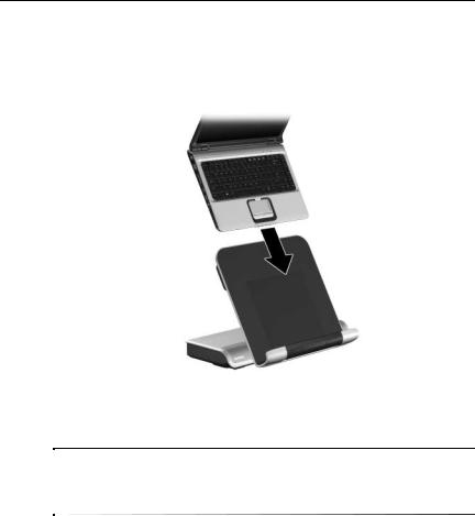
3.Slide the computer into the expansion base with the keyboard facing you.
Sliding the Computer into the Expansion Base
The computer is held in place by a buffer pad, which prevents the computer from shifting out of its proper position in the expansion base.
Maintenance and Service Guide |
1–17 |
Product Description
4.Move the expansion cable to either side of the
expansion base, depending on where the expansion port on your computer is located.
The location of the expansion port on your computer varies by computer series and model.
Extracting the Expansion Cable
It is important to position the cable correctly, so that the cable can move freely. A cable guide assists you in positioning the cable.
1–18 |
Maintenance and Service Guide |

Product Description
5.Press the buttons on the sides of the expansion cable 1.
6.Connect the expansion cable to the computer 2, matching the icon on the computer expansion port with the icon on the end of the expansion cable.
ÄCAUTION: To prevent damage to the expansion port, be sure to correctly align the expansion cable to the expansion port on the computer.
The expansion port may also be called “expansion port 3” in the computer user guide.
Connecting the Expansion Cable
7.If the computer is not already turned on, press the power button on the computer to turn it on.
If the computer connection was made properly, the connection indicator light on the expansion base will light up solid blue.
Maintenance and Service Guide |
1–19 |
Loading...