


HP VISUALIZE B2000 UNIX® Workstations
Parts Removal/Replacement Guide
Manufacturing Part Number: HP Part No. A5983-90060
Edition E0100

© Copyright 2000 Hewlett-Packard Company
Notice
UNIX is a registered trademark in the United States and other countries, licensed exclusively through X/Open Company Limited.
The information contained in this document is subject to change without notice.
Hewlett-Packard assumes no responsibility for the use or reliability of its software on equipment that is not furnished by Hewlett-Packard.
This document contains proprietary information that is protected by copyright. All rights reserved. No part of this document may be photocopied, reproduced or translated to another language without the prior written consent of Hewlett-Packard Company.
HEWLETT-PACKARD WARRANTY STATEMENT
HP PRODUCT |
HP VISUALIZE B2000 Workstations |
REFERENCE |
Warranty and Services/Support Booklet, |
|
Part Number A5014-90140 (E1199) |
The warranty statement shipped with your product supersedes any and all previous workstation Warranty Statements for the Hewlett-Packard Workstations specified herein. Note: This Parts-Only Base Warranty is offered only in the US; for country-specific warranties, please contact your HP country sales representative.
2

Year 2000 Compliance
This HP Year 2000 Warranty is in addition to the HP Standard Commercial Warranties contained in Exhibit E16, HP Terms and Conditions of Sale and Service. HP warrants that each HP hardware, software, and firmware Product delivered under this HP Year 2000 Warranty will be able to accurately process date data (including, but not limited to, calculating, comparing, and sequencing) from, into, and between the twentieth and twenty-first centuries, and the years 1999 and 2000, including leap year calculations, when used in accordance with the Product documentation provided by HP (including any instructions for installing patches or upgrades), provided that all other products (e.g. hardware, software, firmware) used in combination with such HP Product(s) properly exchange date data with it.
If the Specifications require that specific HP Products must perform as a system in accordance with the foregoing warranty, then that warranty will apply to those HP Products as a system, and Customer retains sole responsibility to ensure the Year 2000 readiness of its information technology and business environment. The duration of this warranty extends through January 31, 2001. The remedies available under this warranty will be defined in, and subject to, the terms and limitations of the warranties contained in HP’s standard commercial warranties. To the extent permitted by local law, this warranty applies only to branded HP Products and not to products manufactured by others that may be sold or distributed by HP. This HP Year 2000 Warranty applies only to HP Products shipped after the effective date, July 01, 1998, of this warranty. Nothing in this warranty will be construed to limit any rights or remedies provided elsewhere in the HP Terms and Conditions of Sale and Service with respect to matters other than Year 2000 compliance.
RESTRICTED RIGHTS LEGEND.
Use, duplication, or disclosure by the U.S. government is subject to restrictions as set forth in subdivision (c) (1) (ii) of the Rights in Technical Data and Computer Software Clause in DFARS 252.227.7013. Hewlett-Packard Co., 3000 Hanover St., Palo Alto, CA 94304.
3

4

Contents
1. Getting Started
Safety Warnings. . . . . . . . . . . . . . . . . . . . . . . . . . . . . . . . . . . . . . . . . . . . . .9
Electrostatic Discharge (ESD) Precautions . . . . . . . . . . . . . . . . . . . . . . . .9
Replacement Part Kit Contents . . . . . . . . . . . . . . . . . . . . . . . . . . . . . . . .11
Required Tools . . . . . . . . . . . . . . . . . . . . . . . . . . . . . . . . . . . . . . . . . . . . . .11
Safely Powering Down the B2000 Workstation . . . . . . . . . . . . . . . . . . . .12
Product Exploded Diagram . . . . . . . . . . . . . . . . . . . . . . . . . . . . . . . . . . . .13
2. Parts Replacement Procedures
Front Bezel and Left Side Panel . . . . . . . . . . . . . . . . . . . . . . . . . . . . . . .15
Opening the Front Bezel . . . . . . . . . . . . . . . . . . . . . . . . . . . . . . . . . . . .15
Closing the Front Bezel . . . . . . . . . . . . . . . . . . . . . . . . . . . . . . . . . . . . .16
Left Side Panel . . . . . . . . . . . . . . . . . . . . . . . . . . . . . . . . . . . . . . . . . . . .16
Memory DIMMs . . . . . . . . . . . . . . . . . . . . . . . . . . . . . . . . . . . . . . . . . . . .18
Installing Memory . . . . . . . . . . . . . . . . . . . . . . . . . . . . . . . . . . . . . . . . .18
Removing Memory DIMMs . . . . . . . . . . . . . . . . . . . . . . . . . . . . . . . . . .21
Displaying the Current Memory Configuration . . . . . . . . . . . . . . . . . .23
PCI I/O Card(s) . . . . . . . . . . . . . . . . . . . . . . . . . . . . . . . . . . . . . . . . . . . . .25
Removing I/O Cards . . . . . . . . . . . . . . . . . . . . . . . . . . . . . . . . . . . . . . . .26
Installing I/O Cards . . . . . . . . . . . . . . . . . . . . . . . . . . . . . . . . . . . . . . . .28
CD Drive. . . . . . . . . . . . . . . . . . . . . . . . . . . . . . . . . . . . . . . . . . . . . . . . . . .29
Removing a CD Drive. . . . . . . . . . . . . . . . . . . . . . . . . . . . . . . . . . . . . . .29
Installing a CD Drive . . . . . . . . . . . . . . . . . . . . . . . . . . . . . . . . . . . . . . .31
Floppy Drive. . . . . . . . . . . . . . . . . . . . . . . . . . . . . . . . . . . . . . . . . . . . . . . .37
Installing a Floppy Disk Drive . . . . . . . . . . . . . . . . . . . . . . . . . . . . . . .37
Removing the Floppy Drive . . . . . . . . . . . . . . . . . . . . . . . . . . . . . . . . .41
Verifying the Floppy Drive Configuration. . . . . . . . . . . . . . . . . . . . . . .44
5

Contents
Hard Disk Drive . . . . . . . . . . . . . . . . . . . . . . . . . . . . . . . . . . . . . . . . . . . . 45 Installing a Hard Disk Drive . . . . . . . . . . . . . . . . . . . . . . . . . . . . . . . . 45 Removing a Hard Disk Drive . . . . . . . . . . . . . . . . . . . . . . . . . . . . . . . . 49 Configuring a Hard Disk Drive as a File System . . . . . . . . . . . . . . . . 52
Power Supply . . . . . . . . . . . . . . . . . . . . . . . . . . . . . . . . . . . . . . . . . . . . . . 57
Removing the Power Supply. . . . . . . . . . . . . . . . . . . . . . . . . . . . . . . . . 57
Installing the Power Supply . . . . . . . . . . . . . . . . . . . . . . . . . . . . . . . . . 61
Voltage Regulator Modules (VRMs) . . . . . . . . . . . . . . . . . . . . . . . . . . . . 63
Removing VRMs . . . . . . . . . . . . . . . . . . . . . . . . . . . . . . . . . . . . . . . . . . 63
Installing VRMs . . . . . . . . . . . . . . . . . . . . . . . . . . . . . . . . . . . . . . . . . . 65
System Board . . . . . . . . . . . . . . . . . . . . . . . . . . . . . . . . . . . . . . . . . . . . . . 66
Removing the System Board . . . . . . . . . . . . . . . . . . . . . . . . . . . . . . . . 66
Installing the System Board. . . . . . . . . . . . . . . . . . . . . . . . . . . . . . . . . 68
Fans (I/O and System Board Fan) . . . . . . . . . . . . . . . . . . . . . . . . . . . . . . 72
Removing the I/O Fan . . . . . . . . . . . . . . . . . . . . . . . . . . . . . . . . . . . . . . 72
Installing the I/O Fan . . . . . . . . . . . . . . . . . . . . . . . . . . . . . . . . . . . . . . 75
Removing the System Board Fan . . . . . . . . . . . . . . . . . . . . . . . . . . . . . 75
Installing the System Board Fan . . . . . . . . . . . . . . . . . . . . . . . . . . . . . 76
LCD Display with Power Switch and Display Cable . . . . . . . . . . . . . . . 77 Removing the LCD Display/Power Switch Assembly . . . . . . . . . . . . . 77 Installing the LCD Display/Power Switch Assembly . . . . . . . . . . . . . 78
Speaker . . . . . . . . . . . . . . . . . . . . . . . . . . . . . . . . . . . . . . . . . . . . . . . . . . 79
Removing the Speaker . . . . . . . . . . . . . . . . . . . . . . . . . . . . . . . . . . . . . 79
Installing the Speaker . . . . . . . . . . . . . . . . . . . . . . . . . . . . . . . . . . . . . 81
Real Time Clock Module (Battery) . . . . . . . . . . . . . . . . . . . . . . . . . . . . . 82
3. Wrapping Up
Verifying System Operations. . . . . . . . . . . . . . . . . . . . . . . . . . . . . . . . . . 85
6

Contents
Returning the Defective Exchange Assembly . . . . . . . . . . . . . . . . . . . . .85
7

Contents
8

1 Getting Started
The following important information must be adhered to for proper removal and replacement of all Hewlett-Packard parts.
Safety Warnings
WARNING Removing the device cover may expose sharp edges in the equipment chassis. To avoid injury, use care when installing customer add-on devices.
NOTE Before performing removal/replacement procedures, position the workstation on a cushioned flat, stable surface, such as a table top or workbench.
NOTE Installing the recommended HP replacement part in your B2000 workstation does not affect the regulatory and safety classifications or approvals listed in the original owner’s guide.
Electrostatic Discharge (ESD) Precautions
To prevent damage to the B2000 workstation, observe all of the following ESD precautions while performing removal and replacement procedures:
•Remove all ESD-generating materials from the work area in which you will remove and replace the workstation field replaceable unit(s).
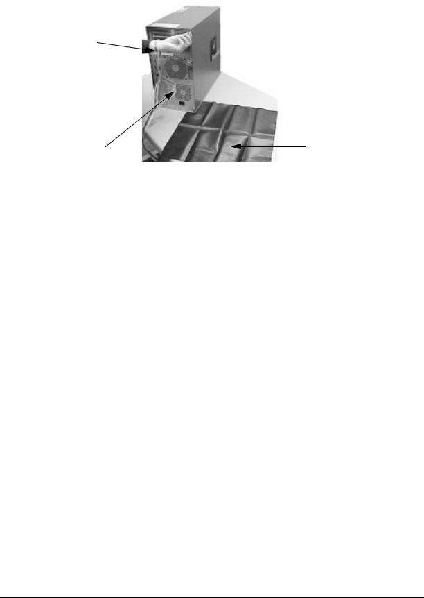
•Open the ESD materials provided with the replacement part kit. Unfold the black conductive sheeting (antistatic mat) and place it under a corner of the workstation. See Figure 1-1. on page 10.
9
Getting Started
Electrostatic Discharge (ESD) Precautions
Figure 1-1. ESD Precautions
Static Strap
Antistatic Mat
Strap attached to Bare Metal
•Wear a static strap to ensure that any accumulated electrostatic charge is discharged from your body to ground. Attach the static-grounding wrist strap by following the instructions on the package. Attach the sticky end of the wrist strap to bare metal on the rear panel of the workstation. See Figure 1-1. on page 10.
•Connect all equipment together, including the static-free mat, static strap, clips attached to the wrist strap, nodes, and peripheral units.
•Keep uninstalled printed circuit boards in their protective antistatic bags.
•Once you have removed printed circuit boards from their protective antistatic bags, handle the printed circuit boards by their edges only.
10 |
Chapter 1 |
Getting Started
Replacement Part Kit Contents
Replacement Part Kit Contents
Take a moment to verify that your kit contains the following contents:
•Part assemblies matching your order information.
•Part Number: A3024-80004, Electrostatic Discharge (ESD) materials.
•Removal/Replacement Instructions.
•B2000 Owner’s Guide
If you are missing any part or documentation, please call your designated service representative.
Required Tools
You will need the following tools for removal/replacement procedures:
•T-10 and/or T-15 Torx drivers
•Light-duty flat-blade screwdriver with a 6-inch (150mm) blade
•ESD materials
Chapter 1 |
11 |
Getting Started
Safely Powering Down the B2000 Workstation
Safely Powering Down the B2000 Workstation
You must complete the following steps before performing any of the removal and replacement procedures:
NOTE Remove any accessory bag(s) and their black tab screws, if present, from the rear of the workstation.
1.Power off the workstation by simply pressing the power switch on the front panel of the workstation. Also, power off the monitor and any attached peripheral devices.
If necessary, shut down the workstation by executing “shutdown -h” as user root). This ensures that all programs are terminated and all data is saved before switching the power off.
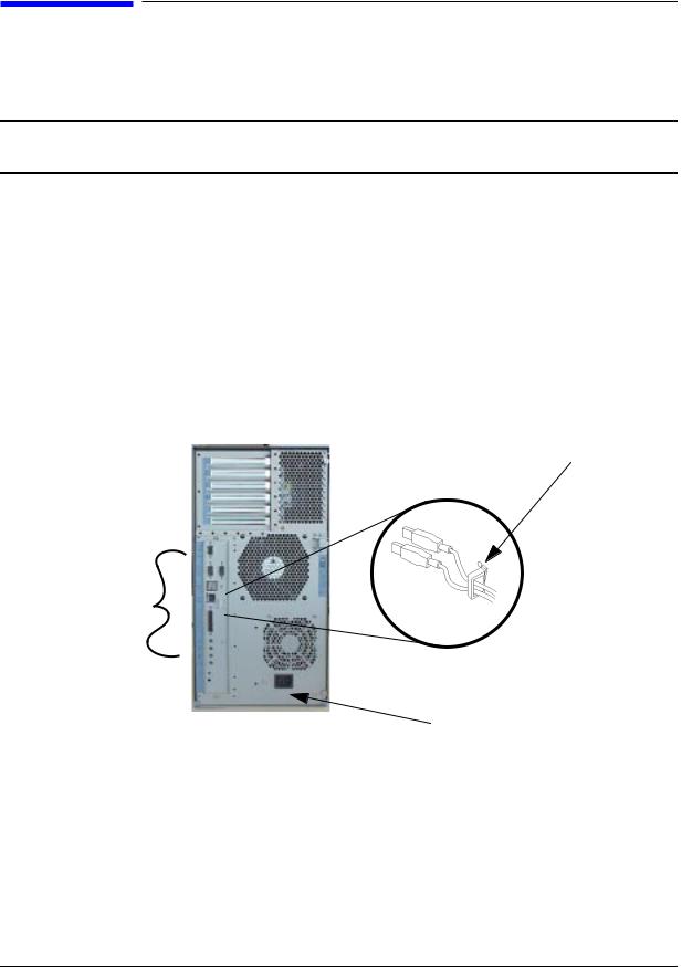
2.After 30 seconds, unplug the workstation’s power cord and all peripheral devices from AC power outlets. Before attempting to move the workstation to a disassembly area, disconnect all peripherals from the back of the system.
Figure 1-2. Unplugging Peripherals
Open the USB clip from the top to release the USB cables.
Disconnect
all peripherals.
Power Cord Connector
3.Place the workstation on a flat, stable surface, such as a tabletop or floor. To protect against scratches, remove miscellaneous debris from the work surface.
12 |
Chapter 1 |
Getting Started
Product Exploded Diagram
Product Exploded Diagram
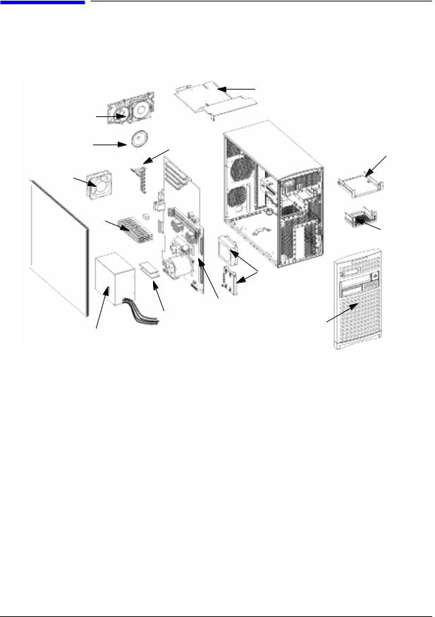
Refer to the figure below for a basic parts overview of the B2000 workstation.
Figure 1-3. Exploded View
|
|
Air Divider |
|
PCI Fan |
|
|
|
Assembly |
PCI |
|
|
Speaker |
CD Drive |
||
Retainer |
|||
Bracket |
|||
|
|
||
System |
|
|
|
Fan |
|
|
|
Memory |
|
Floppy |
|
|
Drive |
||
|
|
||
|
|
Bracket |
|
Left |
|
|
|
Side |
|
|
|
Panel |
|
Hard Disk |
|
|
|
||
|
|
Drive & Bracket |
|
|
System Board |
|
|
|
Voltage Regulator |
Front |
|
|
Bezel |
||
Power Supply |
Modules (VRMs) |
|
Chapter 1 |
13 |

Getting Started
Product Exploded Diagram
14 |
Chapter 1 |
2 Parts Replacement Procedures
This section describes how to remove and replace components and assemblies in the B2000 workstation.
Front Bezel and Left Side Panel
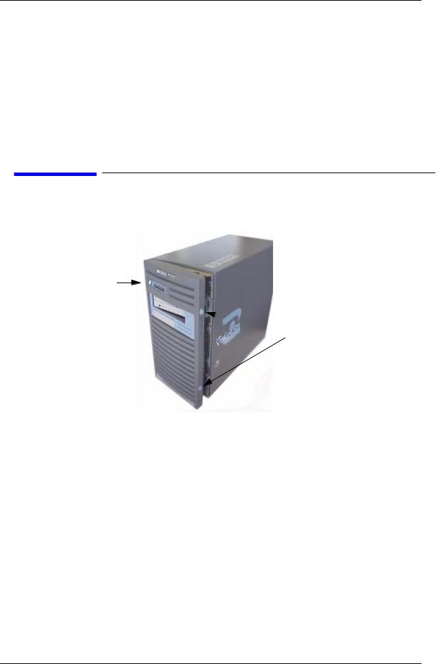
Figure 2-1. Front Bezel
Power
Switch
 Latch Buttons
Opening the Front Bezel
Perform the following steps to open the workstation.
1.Power off the workstation and unplug the workstation.
2.Attach the static-grounding wrist strap by following the instructions on the package. Attach the sticky end of the wrist strap to bare metal on the back panel of the workstation.
3.Unlatch the front bezel by pressing in on the two latch buttons located on the right side of the front bezel. See Figure 2-1.
4.Swing the panel outward on its left snap hinges until the panel releases and place the front bezel in a safe location to avoid damage.
15

Parts Replacement Procedures
Front Bezel and Left Side Panel
Closing the Front Bezel
Perform the following steps to close the workstation.
1.Locate the hinges on the left side of the front bezel, and insert them into the holes located along the left edge of the workstation.
2.Rotate the front bezel inward until you hear the two latch buttons snap in place. The front bezel is now closed.
3.Plug in the workstation’s power cord, and power on the workstation.
Left Side Panel
This section explains how to open and close the left side panel of the workstation. This side panel will have to be opened whenever you need access to the internal components of the workstation.
Opening the Left Side Panel
Perform these steps to open the left side panel.
WARNING Always unplug the workstation’s power cord from the electrical outlet or power source before opening the workstation. Reference “Safely Powering Down the B2000 Workstation” on page 12.
1.Power off the workstation, and unplug the workstation’s power cord from the electrical outlet.
2.Attach the static-grounding wrist strap by following the instructions on the package. Attach the sticky end of the wrist strap to bare metal on the back panel of the workstation. See Figure 1-1. on page 10.
3.Turn the workstation around so its back is facing you. Remove the two T-15 Torx thumbscrews as shown in Figure 2-2.
16 |
Chapter 2 |
Parts Replacement Procedures
Front Bezel and Left Side Panel
4.Grasp the back edge of the left side panel and rotate it outward approximately 30 degrees to the workstation. Next, pull the panel toward you as shown in Figure 2-2. This releases the panel’s top and bottom left side hook hinges from their hinge slots. See Figure 2-2.
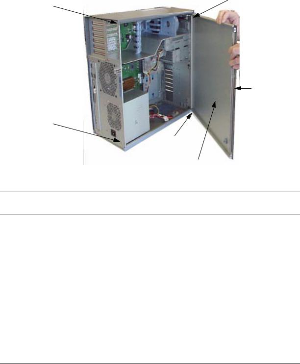
Figure 2-2 Opening the Left Side Panel
Hinge Hook
T-15 Torx
Screw
EMI Gasket
T-15 Torx
Screw
Hinge Slot
Left Side Panel
NOTE The EMI gasket, as shown in Figure 2-2, must not be removed from the side panel.
Closing the Left Side Panel
Perform these steps to close the left side panel.
1.Hold the left side panel so that the top and bottom hinge hooks can be inserted into their hinge slots. See Figure 2-2. Note that the hinge slots are located on the far right edge of the workstation (using the back of the workstation as the reference).
2.Swing the back edge of the panel toward the workstation’s back edge and press the outside edges of the side panel tightly against the workstation. This will ensure a tight seal of the EMI gaskets.
3.Secure the side panel in place and tighten the two T-15 Torx thumbscrews you previously removed.
Chapter 2 |
17 |
Parts Replacement Procedures
Memory DIMMs
Memory DIMMs
This section describes how to remove and replace the Memory DIMMs for the B2000 workstations.
Installing Memory
Perform the following steps to add memory (DIMM cards) to your workstation.
WARNING Turn the workstation off and unplug the power cord before installing additional memory. Reference “Safely Powering Down the B2000 Workstation” on page 12.
CAUTION To prevent damage to the B2000 workstation, observe all of the ESD precautions as described in the “Electrostatic Discharge (ESD) Precautions” on page 9.
1.Open the side panel of the workstation as explained in the section “Opening the Left Side Panel” on page 16 in this chapter.
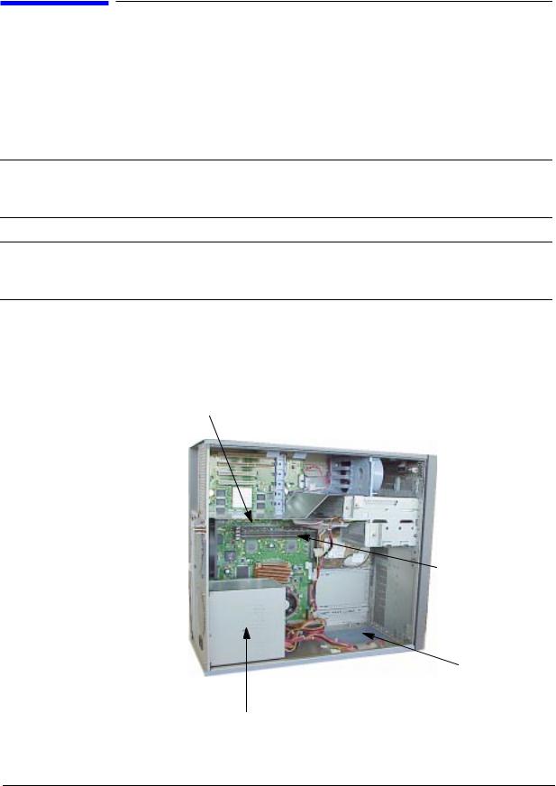
Figure 2-3 View of System Board
DIMM Card
DIMM Connector
 B2000 System
Label
Power Supply
18 |
Chapter 2 |
Parts Replacement Procedures
Memory DIMMs
NOTE Reference the B2000 system label for the correct memory loading sequence.
2.Position the memory slots so they face you as shown in Figure 2-4. Note that Figure 2-4 also provides the loading sequence for the DIMM cards. This loading sequence must be maintained when you install the DIMM cards, but the size of the DIMM card put in each slot can vary. For example, you can install a 256Mbyte card before a 512Mbyte card and then follow the installation of the 512Mbyte card with another 256Mbyte card. The B2000 workstations supports 128 Mbyte, 256 Mbyte and 512 Mbyte DIMM cards.
3.Locate the four internal memory slots, and load the DIMM cards in the slots using the loading sequence provided in Figure 2-4. Note that the label located on the floor of the chassis describes the installation sequence.
Figure 2-4 Memory Card Slot Numbers and Loading Sequence
SL0
SL3
SL1
SL2
Load 1st
Load 4th
Load 2nd
Load 3rd
Memory Slots
(four slots)
Chapter 2 |
19 |
Parts Replacement Procedures
Memory DIMMs
NOTE |
When installing memory, you need to orient the notches on the bottom edge of |
|
the DIMM card so that they are aligned with the keys on the DIMM connector. |
|
See Figure 2-6. The keyed DIMM connectors prevent you from installing the |
|
DIMM cards backwards. |
|
|
For referencing the DIMM loading sequence see the label on the chassis floor. See Figure 2-5.
Figure 2-5. B2000 System Label
Front of the B2000 workstation
Memory Loading Sequence on
B2000 System Label
4.Press downward on the ejector tabs located on each side of the DIMM connector. See Figure 2-6. This opens the connector for DIMM card insertion.
20 |
Chapter 2 |
Figure 2-6 Installing Memory Cards
Step 1
Notches
Step 2
Black
Ejector Tab
Parts Replacement Procedures
Memory DIMMs
Press down on ejector tabs to open them and place the DIMM card in the connector so that your fingers are on the edge of the DIMM card.
Push the DIMM card down firmly and evenly into the connector to be sure it is properly seated.
White
Ejector Tab
5.Place the DIMM card in the connector, lining it up with the guides. Make sure you align the notches on the bottom edge of the DIMM card with the DIMM connector keys. See Figure 2-6.
6.Press firmly and evenly on the DIMM card to ensure that it seats properly.
NOTE The ejector tabs will return to the locked position when the DIMM card is fully seated in the connector.
7.Replace the left side panel as explained in the section “Replacing the left side panel” in this chapter. Plug the power cord into the electrical outlet.
8.Verify that this installation was successful by following the steps in “Displaying the Current Memory Configuration” on page 23.
Removing Memory DIMMs
Perform the following steps to remove memory (DIMM cards) from your workstation.
WARNING Always unplug the workstation’s power cord from the electrical outlet or power source before opening the workstation. Reference “Safely Powering Down the B2000 Workstation” on page 12.
Chapter 2 |
21 |

Parts Replacement Procedures
Memory DIMMs
CAUTION To prevent damage to the B2000 workstation, observe all of the ESD precautions as described in the “Electrostatic Discharge (ESD) Precautions” on page 9.
1.Open the side panel of the workstation as explained in the section “Opening the Left Side Panel” on page 16 in this chapter.
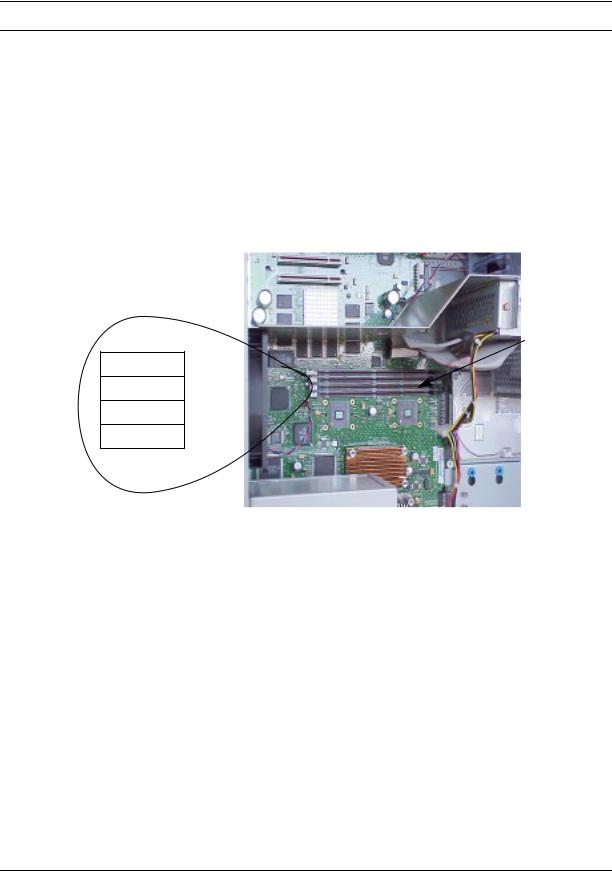
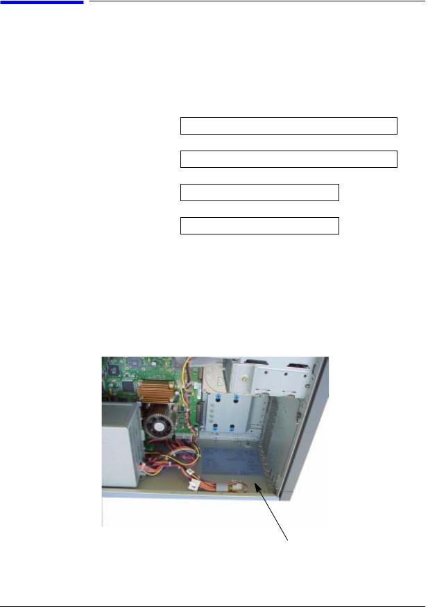
Figure 2-7 System Board View
B2000
System Label
Power
Supply
DIMM connectors
Figure 2-8. DIMM Slot Close-Up on System Board
DIMM Connectors
(4 slots)
22 |
Chapter 2 |
Parts Replacement Procedures
Memory DIMMs
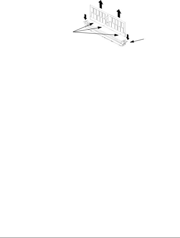
2.Press downward on the ejector tabs located on each side of the DIMM connector. See Figure 2-9. This raises the DIMM card for easy extraction.
Figure 2-9 Removing Memory Cards
Notches
Ejector Tab
3.Lift up evenly on the outside edges of the DIMM card to remove it. See Figure 2-9.
4.Install the remaining DIMM cards in the correct order. See Figure 2-4 or the system label.
5.Replace the left side panel as explained in the section “Replacing the Left Side Panel” in this chapter. Plug the power cord back in to the electrical outlet.
6.Verify that this removal was successful by “Displaying the Current Memory Configuration” on page 23. Note that you can also use SAM and select the
Performance Monitor icon, then the System Properties icon, and in the window that appears, select the tab labeled Memory. See the B2000 Owner’s Guide for more detailed instructions.
Displaying the Current Memory Configuration
The following sample screen output uses the memory command to show a memory configuration table with properly-installed and configured memory.
To display the current memory configuration for your system, from the Information Menu of the boot console interface, follow the directions in “Accessing the Boot Console Interface” earlier in this chapter. Once you are in the Boot Console Interface Main Menu, type the following at the prompt and press Enter:
Main Menu: Enter command> information
This places you in the Information Menu. From here, type the following at the prompt and press Enter:
Information Menu: Enter command> memory
The screen displays status and configuration information for the memory DIMMs installed in your workstation. See the section “Memory Information Sample.”
Chapter 2 |
23 |

Parts Replacement Procedures
Memory DIMMs
Memory Information Sample
The following example shows the memory information when memory modules are properly installed and configured:
MEMORY INFORMATION
MEMORY STATUS TABLE
Slot |
Size |
Status |
---- |
------ |
------------- |
0 |
256MB |
Active |
1 |
256MB |
Active |
2 |
128MB |
Active |
TOTAL MEMORY = 640MB
MEMORY FAULT TABLE |
|
|
|||
Slot |
Size |
Status |
|
|
|
---- |
------ |
------------- |
|
|
|
Active, Installed Memory |
: 640MB of SDRAM |
||||
Deallocated Pages |
: 0 Pages |
|
|||
|
|
|
|
----------- |
|
Available Memory |
: 640MB |
|
|||
Good Memory Required by OS |
: |
0 (Not Initialized) |
|||
|
Memory |
|
|
|
|
HVERSION |
SVERSION |
|
|
||
-------- ---------- |
|
|
|||
0x0860 |
0x0900 |
|
|
||
24 |
Chapter 2 |
Parts Replacement Procedures
PCI I/O Card(s)
PCI I/O Card(s)
This section describes how to remove and install I/O cards.
Your B2000 workstation’s system board has four Peripheral Connect Interface (PCI) slots for option boards. Slots 1 and 2 are full-size PCI slots. Slots 3 and 4 are half-size PCI slots.
Figure 2-10. PCI Card Slot Numbering and Capabilities
Slot 1 64 bits, 33MHz, 5V
Slot 2 64 bits, 33MHz, 5V
Slot 3 32 bits, 33MHz, 5V
Slot 4 32 bits, 33MHz, 5V
The information described in Figure 2-10. is located inside your workstation on the chassis floor. See Figure 2-11. for the physical location of the B2000 workstation label.
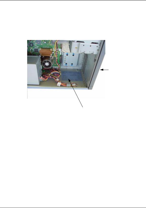
Figure 2-11. Location of B2000 System Label
B2000 System Label
Chapter 2 |
25 |
Parts Replacement Procedures
PCI I/O Card(s)
CAUTION If you are installing an additional graphics card, you must insert the fx card in Slot 1 for optimal performance.
After you connect the monitor to the additional graphics card, you will need to change the graphics path for that monitor. To do this read the section “Displaying and Setting the Monitor Type” in the chapter “The Boot Console Interface” of your Owner’s Guide.
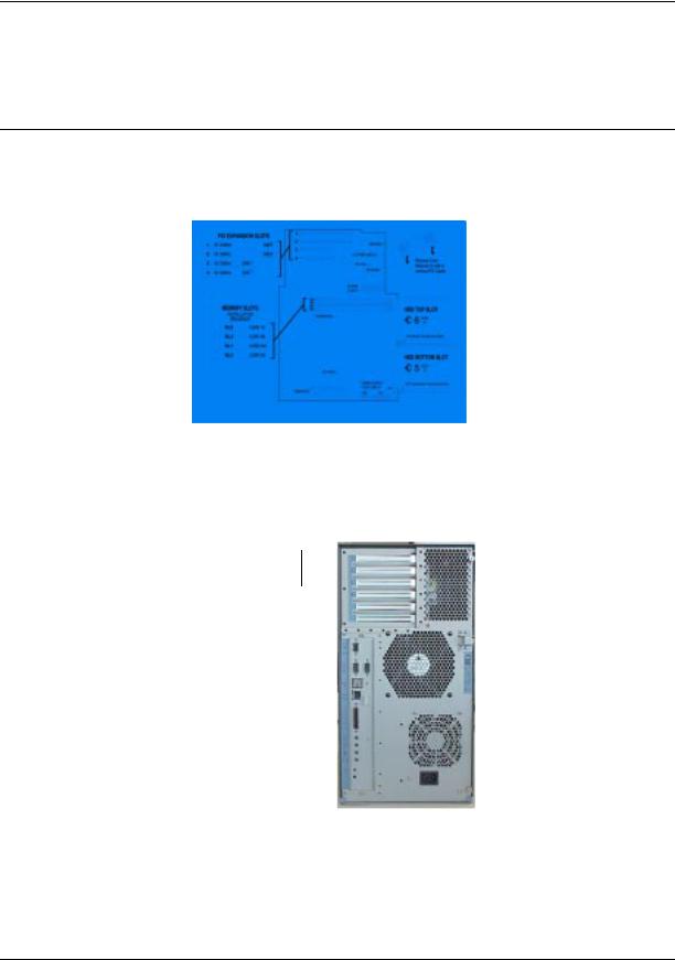
The label on the chassis floor of your workstation contains important information for I/O configuration. See Figure 2-12.
Figure 2-12. B2000 System Label
Note that the four I/O slots as seen from the back of the workstation are labeled from top to bottom starting with one. See Figure 2-13.
Figure 2-13 I/O Slot Numbering
I/O Slot 1
I/O Slot 4 
Removing I/O Cards
You will need a T-15 Torx driver or flathead screwdriver to remove the I/O slot bulkhead screws.
26 |
Chapter 2 |
Parts Replacement Procedures
PCI I/O Card(s)
The steps required for removing an I/O card from the workstation are:
1.Power off the workstation, and unplug the workstation’s power cord from the electrical outlet. Note that when you press the workstation’s power switch, the workstation automatically performs a shutdown -h.
2.Open the side panel of the workstation as explained in the section “Opening the Left Side Panel” in this chapter.
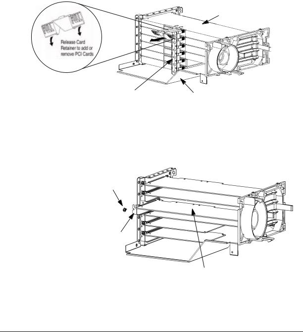
3.Pull downward in the direction of the arrow on both PULL tabs of the I/O card retainer to remove it. See Figure 2-14.
Figure 2-14 Removing the I/O Card Retainer
I/O Card
I/O Card Retainer |
Air Divider |
4.Locate the I/O card you want to remove and using a T-15 Torx driver remove the I/O card’s bulkhead screw as shown in Figure 2-15.
Figure 2-15 Removing the I/O Card
I/O Card
Bulkhead
Torx Screw
I/O Card
Bulkhead
I/O Card Being Removed
5. Pull evenly on the outside edges of the I/O card to remove it. See Figure 2-15.
Chapter 2 |
27 |
 Loading...