


 Loading...
HP Virtual Connect for c-Class BladeSystem Version 4.01
User Guide
Abstract
This document contains user information for HP Virtual Connect version 4.01. This document is for the person who installs, administers, and troubleshoots servers and storage systems. HP assumes you are qualified in the servicing of computer equipment and trained in recognizing hazards in products with hazardous energy levels.
Part Number: 711534-002
June 2013
Edition: 2
© Copyright 2013 Hewlett-Packard Development Company, L.P.
The information contained herein is subject to change without notice. The only warranties for HP products and services are set forth in the express warranty statements accompanying such products and services. Nothing herein should be construed as constituting an additional warranty. HP shall not be liable for technical or editorial errors or omissions contained herein.
Microsoft® and Windows® are U.S. registered trademarks of Microsoft Corporation. Adobe® is a registered trademark of Adobe Systems Incorporated.

Contents |
|
Introduction.................................................................................................................................. |
7 |
What's new.............................................................................................................................................. |
7 |
Virtual Connect documentation.................................................................................................................... |
8 |
Virtual Connect overview............................................................................................................................ |
9 |
HP Virtual Connect Manager........................................................................................................ |
11 |
Configuring browser support .................................................................................................................... |
11 |
Accessing HP Virtual Connect Manager ..................................................................................................... |
12 |
Command Line Interface overview ................................................................................................... |
13 |
Logging on to the HP Virtual Connect Manager GUI .................................................................................... |
13 |
VCM wizards ......................................................................................................................................... |
14 |
HP Virtual Connect Home ......................................................................................................................... |
15 |
About HP Virtual Connect Manager........................................................................................................... |
16 |
Navigating the HP Virtual Connect Manager GUI........................................................................................ |
16 |
Navigation overview ..................................................................................................................... |
16 |
Tree view ..................................................................................................................................... |
16 |
Menu items................................................................................................................................... |
18 |
Activity indicator ........................................................................................................................... |
18 |
Virtual Connect domains.............................................................................................................. |
20 |
Understanding Virtual Connect domains..................................................................................................... |
20 |
Managing domains ................................................................................................................................. |
21 |
Domain Settings (Configuration) screen ............................................................................................ |
22 |
Domain Settings (IP Address) screen................................................................................................. |
23 |
Domain Settings (Enclosures) screen................................................................................................. |
24 |
Domain Settings (Backup/Restore) screen ......................................................................................... |
27 |
Domain Settings (Storage Management Credentials) screen ................................................................ |
29 |
Managing SNMP .................................................................................................................................... |
31 |
SNMP overview ............................................................................................................................ |
31 |
Viewing the system log ............................................................................................................................ |
47 |
System Log (System Log) screen ....................................................................................................... |
47 |
System Log (Configuration) screen ................................................................................................... |
50 |
Managing SSL configuration..................................................................................................................... |
51 |
SSL Certificate Administration (Certificate Info) screen ........................................................................ |
51 |
SSL Certificate Administration (Certificate Signing Request) screen ....................................................... |
54 |
SSL Certificate Administration (Certificate Upload) screen ................................................................... |
56 |
SSH Key Administration screen ....................................................................................................... |
57 |
Web SSL Configuration screen........................................................................................................ |
58 |
HP BladeSystem c-Class enclosures ............................................................................................... |
60 |
Enclosure serial numbers .......................................................................................................................... |
60 |
Using multiple enclosures ......................................................................................................................... |
60 |
Multiple enclosure requirements ................................................................................................................ |
61 |
Enclosures View screen ............................................................................................................................ |
62 |
Enclosures view (multiple enclosures)................................................................................................ |
63 |
Virtual Connect users and roles .................................................................................................... |
64 |
Understanding VC administrative roles....................................................................................................... |
64 |
Contents |
3 |
Managing users ...................................................................................................................................... |
65 |
Local Users screen ......................................................................................................................... |
66 |
Configuring LDAP, RADIUS, and TACACS+ ...................................................................................... |
68 |
Virtual Connect networks ............................................................................................................. |
84 |
Understanding networks and shared uplink sets........................................................................................... |
84 |
Shared uplink sets and VLAN tagging .............................................................................................. |
84 |
Smart Link..................................................................................................................................... |
85 |
Private Networks ........................................................................................................................... |
85 |
VLAN Tunneling Support ................................................................................................................ |
85 |
Managing networks................................................................................................................................. |
86 |
Network Access Groups screen....................................................................................................... |
88 |
Define Network Access Group screen .............................................................................................. |
89 |
Ethernet Settings (Port Monitoring) screen ......................................................................................... |
91 |
Ethernet Settings (Advanced Settings) screen ..................................................................................... |
95 |
Quality of Service........................................................................................................................ |
101 |
IGMP Settings (IGMP Configuration) screen .................................................................................... |
109 |
IGMP Settings (Multicast Filter Set) screen ....................................................................................... |
113 |
Define Ethernet Network screen..................................................................................................... |
114 |
Ethernet Networks (External Connections) screen ............................................................................. |
121 |
Ethernet Networks (Server Connections) screen................................................................................ |
122 |
Managing shared uplink sets .................................................................................................................. |
124 |
Define Shared Uplink Set screen.................................................................................................... |
124 |
Shared Uplink Sets (External Connections) screen ............................................................................ |
134 |
Shared Uplink Sets (Associated Networks) screen ............................................................................ |
137 |
Virtual Connect fabrics .............................................................................................................. |
139 |
Understanding FC fabrics ....................................................................................................................... |
139 |
FabricAttach VC SAN fabrics........................................................................................................ |
139 |
DirectAttach VC SAN fabrics ........................................................................................................ |
142 |
Mixed FabricAttach and DirectAttach VC SAN fabrics ..................................................................... |
146 |
Bay groups ................................................................................................................................. |
147 |
Double-dense mode ..................................................................................................................... |
148 |
Managing fabrics.................................................................................................................................. |
148 |
Define SAN Fabric screen ............................................................................................................ |
149 |
SAN Fabrics (External Connections) screen..................................................................................... |
156 |
SAN Fabrics (Server Connections) screen ....................................................................................... |
158 |
Fibre Channel Settings (Misc.) screen ............................................................................................. |
159 |
Virtual Connect server profiles.................................................................................................... |
160 |
Understanding server profiles.................................................................................................................. |
160 |
Multi-blade servers....................................................................................................................... |
162 |
Flex-10 overview ......................................................................................................................... |
163 |
Flex-10 configuration ................................................................................................................... |
164 |
FlexFabric overview ..................................................................................................................... |
165 |
PXE settings ................................................................................................................................ |
166 |
iSCSI offload and boot................................................................................................................. |
168 |
iSCSI and FCoE port assignments .................................................................................................. |
169 |
Bandwidth assignment ................................................................................................................. |
171 |
Managing MAC, WWN, and server virtual ID settings .............................................................................. |
172 |
Ethernet Settings (MAC Addresses) screen ...................................................................................... |
173 |
Fibre Channel Settings (WWN Settings) screen ............................................................................... |
175 |
Serial Number Settings screen....................................................................................................... |
176 |
Advanced Profile Settings ............................................................................................................. |
177 |
|
Contents 4 |
Managing server profiles ....................................................................................................................... |
178 |
Define Server Profile screen .......................................................................................................... |
178 |
Server Profiles screen ................................................................................................................... |
200 |
Edit Server Profile screen .............................................................................................................. |
201 |
Assigning a server profile with FCoE connections to an HP ProLiant BL680c G7 Server Blade ............... |
208 |
Unassigning a server profile with FCoE connections to an HP ProLiant BL680c G7 Server Blade and deleting the |
|
SAN fabric ................................................................................................................................. |
215 |
General requirements for adding FC or FCoE connections ................................................................ |
219 |
Virtual Connect and Insight Control Server Deployment .............................................................................. |
222 |
Virtual Connect modules ............................................................................................................ |
224 |
Firmware updates.................................................................................................................................. |
224 |
Stacking Links screen ............................................................................................................................. |
225 |
Throughput Statistics screen .................................................................................................................... |
226 |
Enclosure Information screen................................................................................................................... |
228 |
Removing an enclosure ................................................................................................................ |
229 |
Enclosure Status screen .......................................................................................................................... |
230 |
Interconnect Bays Status and Summary screen........................................................................................... |
231 |
Causes for INCOMPATIBLE status .................................................................................................. |
232 |
Ethernet Bay Summary (General Information) screen ........................................................................ |
233 |
Ethernet Bay Summary (Uplink Port Information) screen..................................................................... |
234 |
Ethernet Bay Summary (Server Port Information) screen..................................................................... |
236 |
Ethernet Bay Summary (MAC Address Table) screen ........................................................................ |
237 |
Ethernet Bay Summary (IGMP Multicast Groups) screen .................................................................... |
238 |
Ethernet Bay Summary (Name Server) screen .................................................................................. |
239 |
Ethernet Port Detailed Statistics screen ............................................................................................ |
239 |
FC Port Detailed Statistics screen ................................................................................................... |
248 |
FC Bay Summary screen............................................................................................................... |
250 |
Interconnect Bay Overall Status icon definitions ............................................................................... |
252 |
Interconnect Bay OA Reported Status icon definitions....................................................................... |
252 |
Interconnect Bay VC Status icon definitions ..................................................................................... |
253 |
Interconnect Bay OA Communication Status icon definitions.............................................................. |
253 |
Server Bays Summary screen .................................................................................................................. |
254 |
Double-dense server bay option..................................................................................................... |
254 |
Integrity blade devices ................................................................................................................. |
257 |
Server Bay Overall Status icon definitions ....................................................................................... |
257 |
Server Bay OA Reported Status icon definitions............................................................................... |
258 |
Server Bay VC Status icon definitions ............................................................................................. |
258 |
Server Bay OA Communication Status icon definitions ..................................................................... |
259 |
Server Bay Status screen ........................................................................................................................ |
260 |
Server Bay Status screen - multi-blade servers .................................................................................. |
262 |
Port status conditions ............................................................................................................................. |
264 |
Interconnect module removal and replacement .......................................................................................... |
265 |
Virtual Connect modules............................................................................................................... |
265 |
Upgrading to an HP Virtual Connect 8Gb 24-Port FC Module ........................................................... |
266 |
Upgrading to an HP Virtual Connect 8Gb 20-Port FC Module ........................................................... |
266 |
Upgrading or removing an HP Virtual Connect Flex-10, HP Virtual Connect FlexFabric, or HP Virtual Connect |
|
Flex-10/10D module ................................................................................................................... |
267 |
Upgrading to an HP Virtual Connect FlexFabric module from a VC-FC module .................................... |
269 |
Onboard Administrator modules.................................................................................................... |
269 |
Maintenance and troubleshooting............................................................................................... |
270 |
Domain Status summary ......................................................................................................................... |
270 |
Status icon definitions .................................................................................................................. |
270 |
|
Contents 5 |
Domain Status screen............................................................................................................................. |
271 |
Export support information...................................................................................................................... |
272 |
Reset Virtual Connect Manager ............................................................................................................... |
273 |
Recovering remote enclosures ....................................................................................................... |
273 |
Server profile troubleshooting ................................................................................................................. |
273 |
Server blade power on and power off guidelines............................................................................. |
274 |
Appendix: Using Virtual Connect with nPartitions ......................................................................... |
277 |
Understanding nPartitions....................................................................................................................... |
277 |
Assigning a VC profile to an nPar ........................................................................................................... |
278 |
Mapping profile connections......................................................................................................... |
278 |
Reconfiguring nPars............................................................................................................................... |
278 |
Support and other resources ...................................................................................................... |
280 |
Before you contact HP............................................................................................................................ |
280 |
HP contact information........................................................................................................................... |
280 |
Acronyms and abbreviations...................................................................................................... |
281 |
Documentation feedback ........................................................................................................... |
285 |
Index....................................................................................................................................... |
286 |
Contents 6

Introduction
What's new
The user guide contains information about the following changes in VC 4.01:
•Manageability enhancements:
o Extended support for FCoE protocol on Flex-10/10D and FlexFabric modules, which includes FIP snooping support but is limited to dual-hop configurations. FlexFabric module dual-hop FCoE support is restricted to uplink ports X1-X4.
IMPORTANT: For more information about the installation and limitations for Virtual Connect dual-hop FCoE support, see the HP Virtual Connect Dual-Hop FCoE Cookbook, which can be found on the Installing tab of the HP BladeSystem Technical Resources website (http://www.hp.com/go/bladesystem/documentation).
o Prioritization of critical application traffic with QoS
oMinimum and maximum bandwidth optimization for efficient allocation of bandwidth in virtualized environments with Flex-10 and FlexFabric adapters. Flex-10 and FlexFabric adapter firmware and drivers must be updated to SPP version 2013.02.00, or the latest hotfix thereafter, to take advantage of this enhancement. This feature excludes support for the following adapters:
—HP NC551i Dual Port FlexFabric 10Gb Converged Network Adapter
—HP NC551m Dual Port FlexFabric 10Gb Converged Network Adapter
—HP NC550m 10Gb 2-port PCIe x8 Flex-10 Ethernet Adapter
oVC SNMP MIB enhancements for improved troubleshooting and failure analysis
Virtual Connect SNMP Domain MIB (vc-domain-mib.mib) traps now contain detailed information with the root cause of each event. Update SNMP management stations with the HP MIB Kit version 9.30 prior to installing Virtual Connect version 4.01 to take advantage of this enhancement. Download the update from the HP website (http://h18006.www1.hp.com/products/servers/management/hpsim/mibkit.html).
o Enhanced support for LLDP MIB, Bridge MIB, Interface MIB, and Link aggregation MIB o The domain status alerts screen includes cause and root cause for each alert.
o Customization of VC user roles and privileges
oThe VCM GUI now allows searching for Network Access Groups, modules, interconnect bays, and device bay items from the left navigation tree.
o Configurable long or short LACP timer o VCM CLI TAB key auto-completion
oThe Network, SUS, and hardware pages now display the remote system name instead of the MAC address.
•Security enhancements:
oIGMP Snooping enhancements with multicast group host membership filtering
Introduction 7
o Ability to set session timeout for idle VCM CLI or VCM GUI management sessions
oProtection of VC Enet modules from buffer exhaustion due to flooding of Pause packets from servers
•VCEM compatibility:
oIf you are running VCEM 6.3.1 or later to manage a VC 4.01 domain, the 4.01 domain can be in a VCDG in 3.30 firmware mode or later. To enable new features in VC 4.01, you must upgrade to VCEM 7.2 or later. VCEM 7.2 does not support VC versions prior to 3.30.
oConfigurable role operations must be delegated to one of the following roles if they are to be performed while the domain is in Maintenance Mode: Network, Storage or Domain. Administrators logging into VCM with a Server role account while the domain is in Maintenance mode will be denied access to perform delegated operations such as exporting support files, updating firmware, configuring port monitoring or saving or restoring domain configuration.
oIn VC 4.01, the telemetry port throughput is Enabled by default. You must do the following to add a fresh VC 4.01 installation to your existing VCDG:
—3.30-3.70 VCDG with statistics throughput disabled—Clear the Enable Throughput Statistics checkbox on the Ethernet Settings (Advanced Settings) screen, or run the following VCM CLI command:
set statistics-throughput Enabled=false
—3.30-3.70 VCDG with statistics throughput enabled—Add the domain as is. No change is required.
oIn VC 4.01, the VLAN Capacity is set to Expanded by default. You must do the following to add a fresh VC 4.01 installation to your existing VCDG:
—3.30-3.70 with Legacy VLAN VCDG—You cannot add the domain. Select a different VCDG.
—3.30-3.70 with Enhanced VLAN VCDG—Add the domain as is. No change is required.
•For domains managed by VCEM, a server profile migration of a SAN-booted server between enclosures within the same VCDG or between different VCDGs is not supported.
Virtual Connect documentation
The following Virtual Connect documentation is available on the Installing tab of the HP BladeSystem Technical Resources website (http://www.hp.com/go/bladesystem/documentation):
•HP Virtual Connect for c-Class BladeSystem User Guide
This guide provides details for the Virtual Connect GUI, including descriptions of screen contents and steps to set up domains, profiles, networks, and storage.
•HP Virtual Connect for c-Class BladeSystem Setup and Installation Guide
This guide provides hardware installation and configuration information for initial setup of a Virtual Connect solution. The guide also provides Virtual Connect module component and LED descriptions and guidelines for module installation and upgrades.
•HP Virtual Connect Manager Command Line Interface for c-Class BladeSystem User Guide
This guide provides information for using the Virtual Connect Command Line Interface, including use scenarios and complete descriptions of all subcommands and managed elements.
•HP Virtual Connect Ethernet Cookbook: Single and Multiple Domain (Stacked) Scenarios
This guide helps new Virtual Connect users understand the concepts of and implement steps for integrating Virtual Connect into a network. The scenarios in this guide vary from simplistic to more
Introduction 8
complex while covering a range of typical building blocks to use when designing Virtual Connect solutions.
•HP Virtual Connect Fibre Channel Networking Scenarios Cookbook
This guide details the concepts and implementation steps for integrating HP BladeSystem Virtual Connect Fibre Channel components into an existing SAN fabric. The scenarios in this guide are simplistic while covering a range of typical building blocks to use when designing a solution.
•HP Virtual Connect with iSCSI Cookbook
This guide describes how to configure HP Virtual Connect for an iSCSI environment. It provides tips and troubleshooting information for iSCSI boot and installation.
•HP BladeSystem c-Class Virtual Connect Support Utility User Guide
This guide provides instructions for using the Virtual Connect Support Utility, which enables administrators to upgrade VC-Enet and VC-FC firmware and to perform other maintenance tasks remotely on both HP BladeSystem c7000 and c3000 enclosures using a standalone, Windows-based command line utility.
•Release Notes
Release notes document new features, resolved issues, known issues, and important notes for each release of the Virtual Connect product and support utility.
Virtual Connect overview
HP Virtual Connect is a set of interconnect modules and embedded software for HP BladeSystem c-Class enclosures that simplifies the setup and administration of server connections. Virtual Connect includes the following components:
•VC-Enet modules
o HP Virtual Connect Flex-10 10Gb Ethernet Module for BladeSystem c-Class
o HP Virtual Connect FlexFabric 10Gb/24-port Module for BladeSystem c-Class, which provides the capability to configure Ethernet and FC/FCoE or iSCSI connections
o HP Virtual Connect Flex-10/10D Module for BladeSystem c-Class
•VC-FC modules
o HP 4Gb Virtual Connect Fibre Channel Module for c-Class BladeSystem (VC v4.01 is the last release that will support this module.)
o HP Virtual Connect 4Gb Fibre Channel Module for BladeSystem c-Class (enhanced NPIV) o HP Virtual Connect 8Gb 24-Port Fibre Channel Module for BladeSystem c-Class
o HP Virtual Connect 8Gb 20-Port Fibre Channel Module for BladeSystem c-Class
•HP Virtual Connect Manager
Virtual Connect implements server edge virtualization between the server and the data center infrastructure so networks can communicate with individual servers or pools of HP BladeSystem servers, and so you can upgrade, replace, or move server blades within the enclosures without changes being visible to the external LAN and SAN environments. The external networks connect to a shared resource pool of servers rather than to individual servers. Virtual Connect cleanly separates server enclosure administration from LAN and SAN administration.
Introduction 9
VCM is embedded on VC-Enet modules. You can access VCM through a web-based GUI or CLI. The Onboard Administrator provides a web link to the Virtual Connect GUI. The CLI can be accessed remotely through any SSH session or through the Onboard Administrator CLI.
The VC modules support the HP BladeSystem c7000 Enclosure, the HP BladeSystem c3000 Enclosure, and all the server blades and networks contained within the enclosure. FlexFabric modules are only supported in BladeSystem c7000 enclosures with G6 or newer server blades or Integrity i2 and i4 server blades with Virtual Connect firmware v3.15 and later.
VC-Enet modules enable connectivity to data center Ethernet switches. VC-Enet modules can also be directly connected to other types of devices, such as printers, laptops, rack servers, and network storage devices.
The VC-FC and FlexFabric modules enable connectivity of the enclosure to data center FC switches. Every FC fabric is limited in the number of switches it can support, but the VC-FC modules do not appear as switches to the FC fabric and do not count against FC fabric limits.
A basic Virtual Connect domain includes a single HP c-Class BladeSystem c7000 Enclosure for a total of 16 servers (or up to 32 servers if the double-dense option is enabled), or a single HP c-Class BladeSystem c3000 Enclosure for a total of 8 servers (or up to 16 servers if the double-dense option is enabled). For more information on the double-dense option, see "Double-dense server bay option (on page 254)" . Within the domain, any server blade with the requisite LAN or SAN devices can access any LAN or SAN connected to a VC module, and a server blade of a given processor type (Integrity or X86) can be used as a spare for any server blade of the same processor type within the same enclosure, as long as the server has the requisite number and type of connections. Using network access groups feature, the network administrator can clearly define a separation of networks based on their allowed functionality and prevent the server administrator from assigning specific network combinations in the same server profile.
By stacking (cabling) the VC-Enet modules together within the domain and connecting the VC-FC or FlexFabric module FC uplinks on the same bay of all enclosures to the same FC switch, every server blade in the domain can be configured to access any external network or fabric connection. With this configuration, you can use VCM to deploy and migrate a server blade profile to any server in the Virtual Connect domain without changing external LAN or SAN configurations.
Each version of VC is tested and supported with one or more SPPs. For a list of supported SPPs that must be installed, see the VC release notes.
Introduction 10
HP Virtual Connect Manager
Configuring browser support
Access to the VCM GUI is provided through HTTPS (HTTP exchanged over an SSL-encrypted session) and requires HTTPS (port 443) to be enabled on the management network.
The minimum supported screen resolution is 1024 x 768 with 256 colors. For optimal viewing, HP recommends setting the screen resolution to 1280 x 1024.
Requirements
The VCM web interface requires an XSLT-enabled browser with support for JavaScript 1.3 or the equivalent. The following browsers are supported:
•Microsoft Internet Explorer 8.x and 9.x
•Mozilla Firefox 17.x and ESR 18.x
Browsers that provide the required functionality but do not appear in the previous list are not prevented from running the application, but no support is offered for unlisted browsers.
If you receive a notice that your browser does not have the required functionality, examine your browser settings to ensure they meet the following requirements or contact your administrator.
The use of third-party browser download managers is not supported or recommended when using Virtual Connect. The use of third-party download managers might cause problems with some VC file download functionality not working correctly. For example, when saving the domain configuration, downloading a support information file, and so on.
For IE8 web browsers, the MaxConnectionsPerServer registry setting already exists with a default value of 6, and you should not experience slower responses from the web browser. For more information about increasing the number of browser connections for IE, see the Microsoft website (http://support.microsoft.com/kb/282402).
Mozilla Firefox web browsers default to a higher number of browser connections, so no additional settings are required.
The following browser settings must be enabled before running the application:
•JavaScript
Client-side JavaScript is used extensively by this application. Check the browser settings to make sure JavaScript is enabled before running the application.
•ActiveX
When using Microsoft Internet Explorer with this application, ActiveX must be enabled. Check the browser settings to make sure ActiveX is enabled before running the application.
•Adobe Flash Player
VC 4.01 requires Adobe Flash Player 10.x or higher before you can log in. HP recommends updating to Adobe Flash Player 10.2 or higher. When using IE9, HP recommends using Adobe Flash Player 10.3.181.16 or higher.
HP Virtual Connect Manager 11

The recommended Adobe Flash Player web browser plug-in can be downloaded and installed from the Adobe website (http://get.adobe.com/flashplayer/), or downloaded as a standalone executable from the Adobe website (http://www.adobe.com/downloads).
For the latest Adobe Flash Player Security Bulletin Updates, see the Adobe website (http://www.adobe.com/support/security/index.html#flashplayer).
•Pop-up windows
Pop-up windows must be enabled for certain features to function correctly. Check the browser settings to make sure pop-up blockers are not enabled before running the application.
•Cookies
Cookies must be enabled for certain features to function correctly. Check your browser settings to make sure cookies are enabled before running the application.
Accessing HP Virtual Connect Manager
Access to VCM occurs over the same Ethernet connection used to access the enclosure Onboard Administrator and server blade iLO connections.
Access VCM in one of the following ways:
•If the management network uses dynamic DNS, locate the Default Network Settings label on the primary VC-Enet module, and then type the DNS name into the address field of the web browser.
If the management network does not use dynamic DNS, use the Onboard Administrator to access VCM.
•Log on to the enclosure Onboard Administrator. From the rack overview screen, select the Virtual Connect Manager link from the left navigation tree.
•Log on to the enclosure Onboard Administrator. To display the Interconnect Bays summary screen, select Interconnect Bays in the left navigation tree of the Onboard Administrator user interface. Select the Management URL link for the primary VC-Enet module.
HP Virtual Connect Manager 12
VCM typically operates on the primary VC-Enet module unless that module becomes unavailable, causing a failover to the backup VC-Enet module. If you cannot connect to the primary VC-Enet module, try connecting to the management URL for the backup VC-Enet module.
•Access the VCM CLI remotely through an SSH session by connecting to the VC-Enet module management IP address.
In a multi-enclosure VC domain, VCM runs on the primary module in the primary enclosure. If both the primary and backup modules in the primary enclosure fail, are powered off, or are removed, VCM is not accessible.
Command Line Interface overview
The VCM Command Line Interface can be used as an alternative method for administering the VCM. Using the CLI can be useful in the following scenarios:
•You can develop tools that utilize VCM functions for data collection and for executing provisioning and configuration tasks.
•When no browser is available or you prefer to use a command line interface, you can access management data and perform configuration tasks.
•You can batch commands using script files. These script files can be run manually or scheduled to run automatically.
For more information, see the HP Virtual Connect Manager Command Line Interface for c-Class BladeSystem User Guide on the Installing tab of the HP BladeSystem Technical Resources website (http://www.hp.com/go/bladesystem/documentation).
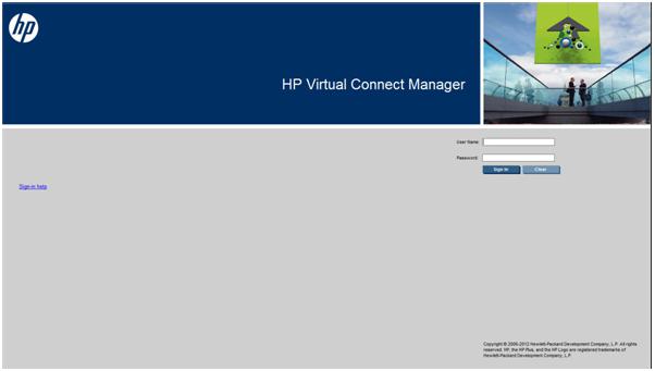
Logging on to the HP Virtual Connect Manager GUI
Log on using the user name (Administrator) and password.
You can optionally specify the authentication method or VCM role at logon.
To specify the authentication method (local, ldap, radius, tacacs), enter the authentication method followed by a colon before the user name. For example, ldap:user1.
To specify the VCM role (domain, network, server, storage), enter the role followed by a colon before the user name. For example, network:user1.
For more information on authentication methods and VCM roles, see "Virtual Connect users and roles (on page 64)."
HP Virtual Connect Manager 13
If the default password for the Administrator user has been changed and needs to be restored, see information about resetting the administrator password and DNS settings in the HP Virtual Connect for c-Class BladeSystem Setup and Installation Guide on the Installing tab of the HP BladeSystem Technical Resources website (http://www.hp.com/go/bladesystem/documentation).
Logon problems might be caused by the following:
•You have recently upgraded the VCM firmware. You might have to clear the browser cache before attempting to log on again.
•The information is not being entered correctly. User names and passwords are case-sensitive.
•The account being entered is not an account for VCM.
•The account being entered has been deleted, disabled, or locked out.
•The password for the account needs to be changed.
•There is no connection to the primary VC-Enet module running VCM.
•VCM is undergoing a failover or recovery.
•The attempted IP sign-in address is not valid for the specified account.
•The attempted IP sign-in address is for a VC-Enet module not running the primary VCM.
•The browser settings are incorrect. See "Configuring browser support (on page 11)."
•You have entered an invalid role or authentication service name.
•Authentication service is disabled, is not correctly configured, or is not up in the server.
VCM wizards
The first time you log in to the VCM GUI, a series of setup wizards automatically launches:
•HP Virtual Connect Manager Domain Setup Wizard
•HP Virtual Connect Manager Network Setup Wizard
HP Virtual Connect Manager 14
•HP Virtual Connect Manager Fibre Channel Setup Wizard
•HP Virtual Connect Manager Server Profile Setup Wizard
These wizards can also be launched at any time using the Tools pull-down menu at the top of the GUI.
For more information about the setup wizards, see the HP Virtual Connect for c-Class BladeSystem Setup and Installation Guide on the Installing tab of the HP BladeSystem Technical Resources website (http://www.hp.com/go/bladesystem/documentation).
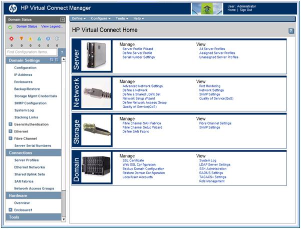
HP Virtual Connect Home
This screen provides access for the management of enclosures, servers, networking, and storage.
HP Virtual Connect Manager 15
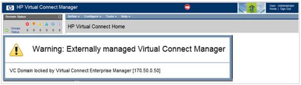
If a red icon with a horizontal white bar appears, an external manager such as VCEM is managing the VCM. Mouse over the icon to display a tool tip with information about the external manager.
About HP Virtual Connect Manager
To view detailed product information, select About HP Virtual Connect Manager from the Help pull-down menu.
Navigating the HP Virtual Connect Manager GUI
Navigation overview
The HP Virtual Connect Manager navigation system consists of a tree view on the left side of the screen that lists all of the system devices. The tree view remains visible at all times, except when using any of the VC wizards.
The right side of the screen, which includes a pull-down menu at the top, displays details for the selected device or activity.
An activity indicator, which is tethered to the bottom of the browser window, displays progress of actions being performed by the VC GUI.
Tree view
The tree view aids in navigation within VCM.
The tree view provides category-based navigation for the major systems configured within VC. When a category is expanded (by clicking the white plus sign in the blue box next to the category), all elements associated with that category are displayed.
Search for logical and physical objects by typing the name of the item in the Find Configuration Items search
field. Use the following syntax to find objects of a specific type:
ItemType: ItemName
Valid values for ItemType include:
•Profile
•Network
•Uplink Set
•SAN Fabric
HP Virtual Connect Manager 16
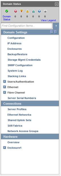
•Network Access Group
•Enclosure
•Module
•Interconnect Bay
•Device Bay
•IGMP filter
•Filter set
•FCoE network
HP Virtual Connect Manager 17
Menu items
The following table lists the items available from the pull-down menu at the top of the screen.
Menu item |
Links to |
|
|
Define |
|
Ethernet Network |
Define Ethernet Network screen (on page 114) |
SAN Fabric |
Define SAN Fabric screen (on page 149) |
Shared Uplink Set |
Define Shared Uplink Set screen (on page 124) |
Network Access Group |
Define Network Access Group screen (on page 89) |
|
|
Server Profile |
Define Server Profile screen (on page 178) |
|
|
Configure |
|
Domain Settings |
Domain Settings (Configuration) screen (on page 22) |
Ethernet Network Settings |
Ethernet Settings (MAC Addresses) screen (on page 173) |
Quality of Service (QoS) |
Quality of Service screen (on page 102) |
IGMP Settings |
IGMP Settings (IGMP Configuration) screen (on page 109) |
Fibre Channel Settings |
Fibre Channel Settings (WWN Settings) screen (on page 175) |
Serial Number Settings |
Serial Number Settings screen (on page 176) |
Local User Accounts |
Local Users screen (on page 66) |
Certificate Administration |
SSL Certificate Administration (Certificate Info) screen (on page 51) |
Tools |
|
Hardware Overview |
Enclosures View ("Enclosures View screen" on page 62) |
Domain Setup Wizard |
Welcome screen for the Domain Setup Wizard |
Network Setup Wizard |
Welcome screen for the Network Setup Wizard |
Fibre Channel Setup Wizard |
Welcome screen for the Fibre Channel Setup Wizard |
Server Profile Setup Wizard |
Welcome screen for the Server Profile Setup Wizard |
Throughput Statistics |
Throughput Statistics screen (on page 226) |
Backup/Restore Domain |
Domain Settings (Backup/Restore) screen (on page 27) |
Configuration |
|
System Log |
System Log (System Log) screen (on page 47) |
Export Support Information |
Export Support Information (on page 272) |
Reset Virtual Connect Manager |
Reset Virtual Connect Manager (on page 273) |
Help |
|
Table of contents |
VC Manager help file table of contents |
Index |
VC Manager help file index |
For This Page |
Help topic specific to the current page |
Virtual Connect Documentation on |
The Virtual Connect Documentation page on the HP website |
hp.com |
(http://www.hp.com/go/bladesystem/documentation) |
About HP Virtual Connect Manager |
Specific information about this Virtual Connect domain |
Activity indicator
The GUI displays current activity in a pane attached to the bottom of the browser window, including a progress bar that displays the activity status graphically. The activity pane includes four controls:
•Up and down arrow buttons scroll through the recent activity history during the current GUI session.
•A collapse button temporarily hides the activity pane until the next activity update.
HP Virtual Connect Manager 18

•A close button hides the activity pane for the current GUI session.
The activity pane is hidden automatically when the activity state is idle. When the activity pane is hidden, a control appears in the bottom-right corner of the GUI. Click the control to display the activity pane.
Only certain, long-running VC activities are reported in the activity pane, including:
•Enclosure Import
•Enclosure Recovery (after NO-COMM)
•Enclosure Recovery (after VC restart or failover)
•Server Profile Operations (create, update, assign and unassign, and delete)
•Module Recovery
•Persist Configuration
HP Virtual Connect Manager 19

Virtual Connect domains
Understanding Virtual Connect domains
A basic VC domain includes a single HP c-Class BladeSystem c7000 Enclosure for a total of 16 servers (or up to 32 servers if the double-dense option is enabled), or a single HP c-Class BladeSystem c3000 Enclosure for a total of 8 servers (or up to 16 servers if the double-dense option is enabled).
Within the domain, any server blade with the requisite LAN or SAN devices can access any LAN or SAN connected to a VC module, and a server blade of a given processor type (Integrity or X86) can be used as a spare for any server blade of the same processor type within the same enclosure, as long as the server has the requisite number and type of connections.
Using Network Access Groups, the network administrator can define and manage groups of networks, assigning them to a profile to prevent the use of networks outside of an assigned group.
VC supports multiple enclosures, allowing up to four c7000 enclosures to be managed within a single Virtual Connect domain for a total of up to 128 servers. Multiple enclosure domains are not supported on c3000 enclosures.
By stacking (cabling) the VC-Enet modules together within the domain and connecting the VC-FC or FlexFabric module FC uplinks on the same bay of all enclosures to the same FC switch, every server blade in the domain can be configured to access any external network or fabric connection. With this configuration, you can use VCM to deploy and migrate a server blade profile to any server in the Virtual Connect domain without changing external LAN or SAN configurations.
The VC domain should be backed up each time changes are made. While the configuration is saved in non-volatile memory and check-pointed to the horizontally adjacent module, HP recommends saving the configuration external to the enclosure. See "Domain Settings (Backup/Restore) screen (on page 27)."
When adding VC interconnect modules to a VC-managed enclosure, wait until the modules have been fully integrated into the current domain and checkpointing is complete before attempting to make configuration changes to the VC domain. These changes include adding or editing networks, fabrics, profiles, and shared uplink sets. Verify that the domain status is clear for the newly added interconnect module before making any changes to the configuration. Modifying the configuration before the integration is complete can cause unexpected behavior such as incorrect/invalid connections in a profile.
After a configuration is changed and changes have stopped, VCM can take up to 90 seconds to save the new information to non-volatile storage and an additional minute to checkpoint to the backup module. If power is removed, the module is reset through the Onboard Administrator interface, or the module is removed from the enclosure during this update, configuration information might be lost. An icon on the VCM banner line indicates that the configuration either has not been saved locally, or it has not been checkpointed.
When a VC-Enet module is powered on or restarted in a VC domain with a large configuration, the module can take up to 6 minutes to initialize. Management access to this module and to VCM hosted on this module is available after the initialization completes.
Virtual Connect domains 20
Managing domains
Use the following screens to manage the VC domain:
•Domain Settings (Configuration) screen (on page 22) o Change the domain name
o Delete a domain
o Configure a customized login screen message
•Domain Settings (IP Address) screen (on page 23) o Set a domain IP address for the VC domain
•Domain Settings (Enclosures) screen (on page 24) o View enclosures in the domain
o Add enclosures to the domain
o Remove enclosures from the domain
•Domain Settings (Backup/Restore) screen (on page 27) o Create a backup file of the VC domain configuration o Restore a configuration that has been lost
o Revert to a previously saved configuration
•Domain Settings (Storage Management Credentials) screen (on page 29) o Add a storage management credential to the domain
o Remove a storage management credential from the domain
Virtual Connect domains 21

Domain Settings (Configuration) screen
Use this screen to change the domain name, delete a domain, and configure a customized login screen message. To access this screen, click Configuration in the left navigation tree, or select Domain Settings from the Configure menu. Only users with domain role permission can make changes on this screen.
The following table describes the available actions in the Domain Settings (Configuration) screen. Clicking another link in the pull-down menu or left navigation tree causes current edits that have not been applied to be lost.
Task |
Action |
|
|
Change the domain name |
Enter the revised domain name, and then click Apply. |
|
|
Display single-dense server bays |
Click the checkbox next to the appropriate selection. Available if |
|
double-dense compatibility is selected during import. |
|
|
Delete a domain |
Verify that the correct domain name is displayed, and then click |
|
Delete Domain. See "Deleting a domain (on page 22)." |
Add banner text to the login screen |
Select the Enable Display of Banner on User Login checkbox, enter a |
|
customized message in the Banner Text field (up to 1500 printable |
|
ASCII characters in length), and then click Apply. Users are required |
|
to acknowledge the banner text before they can log in. |
|
|
Clear changes and remain on this screen |
Click Revert. |
Save changes |
Click Apply. |
Deleting a domain
Virtual Connect domains 22

CAUTION: Deleting a domain returns all settings to factory default. This action cannot be undone.
1.Power off all servers that are associated with profiles. See "Server Bay Status screen (on page 260)."
2.Navigate to the Domain Settings (Configuration) screen (on page 22).
3.Click Delete. A domain name confirmation window is displayed.
4.Enter the name of the domain to be deleted. This should be the name of the domain you are currently logged into, displayed in the Virtual Connect Domain Name box on the Domain Settings (Configuration) screen (on page 22).
5.Click OK.
If deleting a domain that was using MAC addresses predefined by HP, the administrator should also update the "Teaming" driver configuration file on the host OS. Otherwise, the driver reinitializes to the saved MAC address predefined by HP and not the factory default value.
When a VCM domain is deleted, VCM resets VC 8Gb 24-Port FC Modules to a factory default condition. This operation can take up to 50 seconds per VC 8Gb 24-Port FC Module.
Domain Settings (IP Address) screen
Use this screen to set a domain IP address for the Virtual Connect domain. This IP address is then consistent, regardless of which module is primary within the domain.
The optional domain IP address setting allows for a consistent IP address that is independent of the interconnect module on which it is running. If set, this IP address must be unique within the network and must be different than the IP address of the module itself. If this IP address is not set, the VC Manager can still be reached through the IP address of the host VC-Enet module.
To use an optional domain IP address, select the Use Domain IP address checkbox, and then enter the IP Address, Subnet Mask, and Default Gateway.
NOTE: Even if a domain IP address is provided, the normal IP address assigned to the interconnect bay can still be used.
Virtual Connect domains 23

The following table describes the available actions in the Domain Settings (IP Address) screen. Clicking another link in the pull-down menu or left navigation tree causes current edits that have not been applied to be lost.
Task |
Action |
|
|
Use a VC domain IP address |
Select the box next to Use Virtual Connect Domain IP Address, and |
|
then enter the IP Address, Subnet Mask, and Gateway. |
Save changes |
Click Apply. |
Cancel without saving changes |
Click Cancel. |
Domain Settings (Enclosures) screen
Use this screen to view, add, or remove enclosures in the domain. When importing an enclosure, consider the following:
•After an enclosure import, the VCM CLI shows the Stacking Links Connections Status as "Failed" until all modules are initialized. Depending on the actual configuration, this can take up to 30 seconds.
•If an enclosure import is attempted with a server blade in a failed state, VCM might incorrectly report an error when an error does not exist. If the import times out with an error, close the browser and log in again to verify that the import was successful. Use the OA to verify the working state of all server blades.
For more information on adding and importing a remote enclosure, see "Adding and importing a remote enclosure (on page 25)."
Multiple enclosures are supported only if an appropriate primary and backup VC module is running in the local enclosure. For more information about connecting multiple enclosures, see the HP Virtual Connect for
Virtual Connect domains 24

c-Class BladeSystem Setup and Installation Guide on the Installing tab of the HP BladeSystem Technical Resources website (http://www.hp.com/go/bladesystem/documentation).
The following table describes the columns within the Domain Settings (Enclosures) screen.
Column |
Description |
|
|
Enclosure ID |
Assigned ID of the enclosure |
|
|
Enclosure name |
Name of the enclosure |
Enclosure serial number |
Serial number of the enclosure |
Rack name |
Name of the rack (assigned through the Onboard Administrator) |
OA IP Address |
"Local Enclosure" indicates this enclosure is managed by the local Onboard |
|
Administrator |
Status |
Displays whether the enclosure has been imported |
Action |
Perform import and delete operations. |
The following table describes the available actions in the Domain Settings (Enclosures) screen. Clicking another link in the pull-down menu or left navigation tree causes current edits that have not been applied to be lost.
Task |
Action |
|
|
Import an enclosure |
Click the Import link in the Action column, or left-click on the enclosure |
|
row, right-click to display a menu, and then select Import. |
|
|
Add and import a remote |
Click Find below the table, or right-click inside the table, and then select |
enclosure ("Adding and |
Find. |
importing a remote enclosure" on |
|
page 25) |
|
Remove a remote enclosure |
Click the Delete link in the Action column, or left-click on the enclosure |
("Removing a remote enclosure" |
row, right-click to display a menu, and then select Delete. |
on page 27) |
|
Adding and importing a remote enclosure
Adding and importing a remote enclosure requires domain and server role permissions. Virtual Connect Manager supports up to four c7000 enclosures in a single domain.
Virtual Connect domains 25
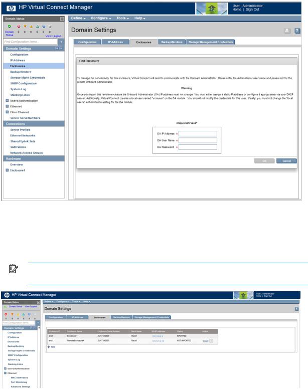
To add a remote enclosure:
1.Click Find on the Domain Settings (Enclosures) screen (on page 24).
2.Type in the following information:
o Onboard Administrator IP Address o Onboard Administrator User Name o Onboard Administrator Password
3.Click OK.
IMPORTANT: No more than four enclosures can be found or imported. If an enclosure is unintentionally found, it can be removed by clicking Delete.
4.Click the Import link in the Action column. -or-
Left-click on the enclosure row, right-click to display a menu, and then select Import.
Virtual Connect domains 26

Virtual Connect Manager imports the enclosure and provides status information.
Removing a remote enclosure
To remove a remote enclosure, disassociate all profiles, networks, port sets, and port monitors from the enclosure. If the enclosure is currently in a No-COMM state, the remote enclosure remains in VC Mode. Take the enclosure out of VC mode manually with the OA command line for that enclosure.
To remove a remote enclosure:
1.Go to the Domain Settings (Enclosures) screen (on page 24).
2.Click the Delete link in the Action column. -or-
Left-click on the enclosure row, right-click to display a menu, and then select Delete.
Domain Settings (Backup/Restore) screen
Use this screen to create a backup file of the Virtual Connect domain configuration to restore a configuration that has been lost, or to revert to a previously saved configuration. The domain configuration includes network definitions, MAC address settings, WWN settings, Fibre Channel fabric settings, local user accounts, and server profile definitions. The backup file stores the same information that is check-pointed between the primary and backup modules during normal operation.
Virtual Connect domains 27

Only users with Save Domain Configuration role operation permissions can perform a backup operation. Only users with Restore Domain Configuration role operation permissions can perform a domain restore. For more information, see "Role Management (Role Operations) screen (on page 83)."
CAUTION: To avoid loss of data, do not close the browser window containing the VCM GUI during backup or restore operations. If the browser window is closed, you must close and then restart the browser.
To back up a domain configuration:
1.Enter an encryption key to encrypt the configuration file.
2.Click Backup Configuration.
3.Navigate to the hard drive location where you want to save the configuration file.
4.Name the file (usually the domain name), and then click Save.
To restore a domain configuration:
1.Click Browse, navigate to the location of the saved configuration file, select the file, and then click
Open.
2.Select the Ignore enclosure serial number in restored configuration file checkbox to restore a configuration that was generated on another enclosure. If this item is not selected, a configuration generated on another enclosure is rejected. This option is relevant to the primary/local enclosure only.
CAUTION: Restoring a Virtual Connect domain configuration from a backup file that was created on another Virtual Connect domain is not supported and can cause serious faults within this and other Virtual Connect Domains within the environment. The restore selection and configuration files should only be used to restore the same previously existing domain.
Virtual Connect domains 28

3.Select the Ignore firmware version in restored configuration file checkbox to allow restoring a domain configuration from a backup file that was created using a different version of VC firmware.
IMPORTANT: Restoring a configuration from a backup file saved by firmware version later than what is currently running is not supported. For example, if you are currently running Virtual Connect v3.60, you can restore a configuration from a backup file that was created using v3.10 or v3.51, but not v3.70.
4.Enter the appropriate key if the configuration file is encrypted.
5.Click Restore Configuration.
6.Confirm the domain configuration to be restored, and then click OK.
If restoring a configuration file that has multiple enclosures, each remote enclosure must be re-authenticated for security reasons.
For more information, see "Recovering remote enclosures (on page 273)."
Domain Settings (Storage Management Credentials) screen
Use this screen to manage the credentials of HP P4000 series devices in the domain. The IP address is the IP address of the LHN CMC interface. This IP address must be accessible from the same management network where Virtual Connect and Onboard Administrator reside.
The following table describes the columns within the Domain Settings (Storage Management Credentials) screen.
Column |
Description |
|
|
Name |
Name for the iSCSI storage management |
|
|
Virtual Connect domains 29

Column |
Description |
|
|
IP address |
iSCSI storage management IPv4 address |
Username |
An administrator for the storage management |
Action |
Perform edit and delete operations |
The following table describes the available actions in the Domain Settings (Storage Management Credentials) screen. Clicking another link in the pull-down menu or left navigation tree causes current edits that have not been applied to be lost.
Task |
Action |
|
|
Add a credential ("Adding or |
Click Add below the table, or right-click inside the table, and then select |
editing a credential" on page 30) |
Add. |
Edit a credential ("Adding or |
Click the Edit link in the Action column, or left-click on the credential row, |
editing a credential" on page 30) |
right-click to display a menu, and then select Edit. |
Delete a credential |
Click the Delete link in the Action column, or left-click on the credential |
|
row, right-click to display a menu, and then select Delete. |
Adding or editing a credential
Use this screen to add a storage management credential.
To add a credential:
1.Enter a name for the iSCSI storage management in the Name field.
2.Enter the IPv4 address for the iSCSI storage management in the IP address field.
3.Enter an administrator user name for the storage management in the Username field.
Virtual Connect domains 30
Loading...