


VISUALIZE B2000

HP VISUALIZE B2000 Owner’s Guide
HP VISUALIZE Workstations
Manufacturing Part Number: HP Part No. A5983-90001
Edition E1199

2
© Copyright 1999 Hewlett-Packard Company
Notice
UNIX is a registered trademark in the United States and other
countries, licensed exclusively through X/Open Company Limited.
The information contained in this document is subject to change without
notice.
Hewlett-Packard assumes no responsibility for the use or reliability of its
software on equipment that is not furnished by Hewlett-Packard.
This document contains proprietary information that is protected by
copyright. All rights reserved. No part of this document may be
photocopied, reproduced or translated to another language without the
prior written consent of Hewlett-Packard Company.
HEWLETT-PACKARD WARRANTY STATEMENT
HP PRODUCT HP VISUALIZE B2000 Workstations
REFERENCE Warranty and Services/Support Booklet,
Part Number A5014-90140 (E1199)
The warranty statement shipped with your product supersedes any and
all previous workstation Warranty Statements for the Hewlett-Packard
Workstations specified herein. Note: This Parts-Only Base Warranty is
offered only in the US; for country-specific warranties, please contact
your HP country sales representative.

3
Year 2000 Compliance
This HP Year 2000 Warranty is in addition to the HP Standard
Commercial Warranties contained in Exhibit E16, HP Terms and
Conditions of Sale and Service. HP warrants that each HP hardware,
software, and firmware Product delivered under this HP Year 2000
Warranty will be able to accurately process date data (including, but not
limited to, calculating, comparing, and sequencing) from, into, and
between the twentieth and twenty-first centuries, and the years 1999
and 2000, including leap year calculations, when used in accordance with
the Product documentation provided by HP (including any instructions
for installing patches or upgrades), provided that all other products (e.g.
hardware, software, firmware) used in combination with such HP
Product(s) properly exchange date data with it.
If the Specifications require that specific HP Products must perform as a
system in accordance with the foregoing warranty, then that warranty
will apply to those HP Products as a system, and Customer retains sole
responsibility to ensure the Year 2000 readiness of its information
technology and business environment. The duration of this warranty
extends through January 31, 2001. The remedies available under this
warranty will be defined in, and subject to, the terms and limitations of
the warranties contained in HP’s standard commercial warranties. To
the extent permitted by local law, this warranty applies only to branded
HP Products and not to products manufactured by others that may be
sold or distributed by HP. This HP Year 2000 Warranty applies only to
HP Products shipped after the effective date, July 01, 1998, of this
warranty. Nothing in this warranty will be construed to limit any rights
or remedies provided elsewhere in the HP Terms and Conditions of Sale
and Service with respect to matters other than Year 2000 compliance.
RESTRICTED RIGHTS LEGEND.
Use, duplication, or disclosure by the U.S. government is subject to
restrictions as set forth in subdivision (c) (1) (ii) of the Rights in
Technical Data and Computer Software Clause in DFARS 252.227.7013.
Hewlett-Packard Co., 3000 Hanover St., Palo Alto, CA 94304.

4

Contents
5
1. Overview
Product Information . . . . . . . . . . . . . . . . . . . . . . . . . . . . . . . . . . . . . . . . .17
Key Features. . . . . . . . . . . . . . . . . . . . . . . . . . . . . . . . . . . . . . . . . . . . . .17
Front Panel Components . . . . . . . . . . . . . . . . . . . . . . . . . . . . . . . . . . . .19
Rear Panel Components. . . . . . . . . . . . . . . . . . . . . . . . . . . . . . . . . . . . .22
Memory . . . . . . . . . . . . . . . . . . . . . . . . . . . . . . . . . . . . . . . . . . . . . . . . . .31
Monitors . . . . . . . . . . . . . . . . . . . . . . . . . . . . . . . . . . . . . . . . . . . . . . . . .31
Getting Started . . . . . . . . . . . . . . . . . . . . . . . . . . . . . . . . . . . . . . . . . . . . .32
Operating System Overview . . . . . . . . . . . . . . . . . . . . . . . . . . . . . . . . .32
Information You Need to Record . . . . . . . . . . . . . . . . . . . . . . . . . . . . . .33
Gathering Required Information. . . . . . . . . . . . . . . . . . . . . . . . . . . . . .34
Powering on the Workstation for the First Time . . . . . . . . . . . . . . . . .35
Documentation . . . . . . . . . . . . . . . . . . . . . . . . . . . . . . . . . . . . . . . . . . . .37
2. Using Your CD Drive
CD Media Description. . . . . . . . . . . . . . . . . . . . . . . . . . . . . . . . . . . . . . . .41
Caring for CDs . . . . . . . . . . . . . . . . . . . . . . . . . . . . . . . . . . . . . . . . . . . .41
Operating the CD Drive . . . . . . . . . . . . . . . . . . . . . . . . . . . . . . . . . . . . . .42
CD Drive . . . . . . . . . . . . . . . . . . . . . . . . . . . . . . . . . . . . . . . . . . . . . . . . .42
Loading and Unloading a CD . . . . . . . . . . . . . . . . . . . . . . . . . . . . . . . .45
Locating Help . . . . . . . . . . . . . . . . . . . . . . . . . . . . . . . . . . . . . . . . . . . . .47
Mounting and Unmounting a CD. . . . . . . . . . . . . . . . . . . . . . . . . . . . . . .48
Mounting a CD Using SAM. . . . . . . . . . . . . . . . . . . . . . . . . . . . . . . . . .48
Unmounting a CD Using SAM . . . . . . . . . . . . . . . . . . . . . . . . . . . . . . .51
Verifying the CD Drive Operation . . . . . . . . . . . . . . . . . . . . . . . . . . . . . .54
Configuring the CD Driver . . . . . . . . . . . . . . . . . . . . . . . . . . . . . . . . . . . .55
Audio Control for the CD Drive . . . . . . . . . . . . . . . . . . . . . . . . . . . . . . . .56
Installing the xmcd Utility . . . . . . . . . . . . . . . . . . . . . . . . . . . . . . . . . .56
Using the xmcd Utility. . . . . . . . . . . . . . . . . . . . . . . . . . . . . . . . . . . . . .57

6
Contents
3. Using Your 3.5-Inch Floppy Disk Drive
Operating the Floppy Drive. . . . . . . . . . . . . . . . . . . . . . . . . . . . . . . . . . . 61
Floppy Disk Drive. . . . . . . . . . . . . . . . . . . . . . . . . . . . . . . . . . . . . . . . . 61
Using the Floppy Diskette . . . . . . . . . . . . . . . . . . . . . . . . . . . . . . . . . . 62
Using Device Files. . . . . . . . . . . . . . . . . . . . . . . . . . . . . . . . . . . . . . . . . 63
Formatting a New Diskette . . . . . . . . . . . . . . . . . . . . . . . . . . . . . . . . . 66
Transferring Data To and From a Floppy Diskette . . . . . . . . . . . . . . 67
Listing the Files on a Floppy Diskette. . . . . . . . . . . . . . . . . . . . . . . . . 68
Troubleshooting. . . . . . . . . . . . . . . . . . . . . . . . . . . . . . . . . . . . . . . . . . . 68
Verifying the Floppy Drive Configuration. . . . . . . . . . . . . . . . . . . . . . . . 69
Additional Floppy Drive Information . . . . . . . . . . . . . . . . . . . . . . . . . . . 70
Configuring the Floppy Driver. . . . . . . . . . . . . . . . . . . . . . . . . . . . . . . 70
For More Information. . . . . . . . . . . . . . . . . . . . . . . . . . . . . . . . . . . . . . 70
4. Changing Your Workstation’s Hardware Configuration
Front Panel. . . . . . . . . . . . . . . . . . . . . . . . . . . . . . . . . . . . . . . . . . . . . . . . 76
Opening the Front Panel . . . . . . . . . . . . . . . . . . . . . . . . . . . . . . . . . . . 76
Closing the Front Panel . . . . . . . . . . . . . . . . . . . . . . . . . . . . . . . . . . . . 77
Left Side Panel . . . . . . . . . . . . . . . . . . . . . . . . . . . . . . . . . . . . . . . . . . . . . 78
Opening the Left Side Panel. . . . . . . . . . . . . . . . . . . . . . . . . . . . . . . . . 78
Closing the Left Side Panel . . . . . . . . . . . . . . . . . . . . . . . . . . . . . . . . . 80
I/O Cards. . . . . . . . . . . . . . . . . . . . . . . . . . . . . . . . . . . . . . . . . . . . . . . . . . 81
Removing I/O Cards . . . . . . . . . . . . . . . . . . . . . . . . . . . . . . . . . . . . . . . 83
Installing I/O Cards . . . . . . . . . . . . . . . . . . . . . . . . . . . . . . . . . . . . . . . 85
Fans. . . . . . . . . . . . . . . . . . . . . . . . . . . . . . . . . . . . . . . . . . . . . . . . . . . . . . 87
Removable Media Devices . . . . . . . . . . . . . . . . . . . . . . . . . . . . . . . . . . . . 88
Installing a CD Drive . . . . . . . . . . . . . . . . . . . . . . . . . . . . . . . . . . . . . . 88
Removing a CD Drive . . . . . . . . . . . . . . . . . . . . . . . . . . . . . . . . . . . . . . 95
Installing a Floppy Disk Drive. . . . . . . . . . . . . . . . . . . . . . . . . . . . . . 101

Contents
7
Removing a Floppy Disk Drive . . . . . . . . . . . . . . . . . . . . . . . . . . . . . .109
Hard Disk Drives. . . . . . . . . . . . . . . . . . . . . . . . . . . . . . . . . . . . . . . . . . .116
Installing a Hard Disk Drive. . . . . . . . . . . . . . . . . . . . . . . . . . . . . . . .117
Removing a Hard Disk Drive. . . . . . . . . . . . . . . . . . . . . . . . . . . . . . . .123
Configuring a Hard Disk Drive as a File System. . . . . . . . . . . . . . . .127
Memory Cards . . . . . . . . . . . . . . . . . . . . . . . . . . . . . . . . . . . . . . . . . . . . .132
Installing Additional Memory . . . . . . . . . . . . . . . . . . . . . . . . . . . . . . .132
Removing Memory . . . . . . . . . . . . . . . . . . . . . . . . . . . . . . . . . . . . . . . .138
Monitor Type . . . . . . . . . . . . . . . . . . . . . . . . . . . . . . . . . . . . . . . . . . . . . .141
Setting the Monitor Type at Power On. . . . . . . . . . . . . . . . . . . . . . . .141
Setting the Monitor Type from the Boot Console Interface. . . . . . . .142
Setting the Monitor Type Using SAM. . . . . . . . . . . . . . . . . . . . . . . . .142
Troubleshooting Monitor Problems. . . . . . . . . . . . . . . . . . . . . . . . . . .145
5. The Boot Console Interface
Accessing the Boot Console Interface. . . . . . . . . . . . . . . . . . . . . . . . . . .149
Boot Console Interface Features. . . . . . . . . . . . . . . . . . . . . . . . . . . . . . .151
Booting Your System. . . . . . . . . . . . . . . . . . . . . . . . . . . . . . . . . . . . . . . .156
Searching for Bootable Media. . . . . . . . . . . . . . . . . . . . . . . . . . . . . . . . .159
Resetting Your System . . . . . . . . . . . . . . . . . . . . . . . . . . . . . . . . . . . . . .160
Displaying and Setting Paths. . . . . . . . . . . . . . . . . . . . . . . . . . . . . . . . .161
Displaying and Setting the Monitor Type . . . . . . . . . . . . . . . . . . . . . . .163
The Monitor Command . . . . . . . . . . . . . . . . . . . . . . . . . . . . . . . . . . . .163
Displaying the Current Monitor Configuration . . . . . . . . . . . . . . . . .165
Setting the Monitor Type. . . . . . . . . . . . . . . . . . . . . . . . . . . . . . . . . . .166
Setting the Monitor Type with SAM. . . . . . . . . . . . . . . . . . . . . . . . . .167
Setting the Monitor Type at Power On. . . . . . . . . . . . . . . . . . . . . . . .170
Troubleshooting Monitor Problems. . . . . . . . . . . . . . . . . . . . . . . . . . .171

8
Contents
Changing the Console to an External Terminal. . . . . . . . . . . . . . . . . . 172
Displaying the Current Memory Configuration . . . . . . . . . . . . . . . . . . 173
Memory Information Sample . . . . . . . . . . . . . . . . . . . . . . . . . . . . . . . 174
Displaying the Status of the System I/O. . . . . . . . . . . . . . . . . . . . . . . . 175
Setting the Auto Boot and Auto Search Flags . . . . . . . . . . . . . . . . . . . 176
Displaying and Setting the Security Mode. . . . . . . . . . . . . . . . . . . . . . 178
Displaying and Setting the Fastboot Mode. . . . . . . . . . . . . . . . . . . . . . 179
Displaying the LAN Station Address . . . . . . . . . . . . . . . . . . . . . . . . . . 180
Displaying System Information. . . . . . . . . . . . . . . . . . . . . . . . . . . . . . . 181
6. Solving Problems
Common Problems and Solutions . . . . . . . . . . . . . . . . . . . . . . . . . . . . . 185
Dealing with a Boot Failure. . . . . . . . . . . . . . . . . . . . . . . . . . . . . . . . . . 189
Memory Failures . . . . . . . . . . . . . . . . . . . . . . . . . . . . . . . . . . . . . . . . . . 191
LCD Information . . . . . . . . . . . . . . . . . . . . . . . . . . . . . . . . . . . . . . . . . . 192
LCD Fan Failures and Warnings . . . . . . . . . . . . . . . . . . . . . . . . . . . . 193
Troubleshooting Monitor Problems. . . . . . . . . . . . . . . . . . . . . . . . . . . . 195
Running System Verification Tests . . . . . . . . . . . . . . . . . . . . . . . . . . . 196
A. Safety and Regulatory Statements
Declaration of Conformity . . . . . . . . . . . . . . . . . . . . . . . . . . . . . . . . . . . 199
Emissions Regulations. . . . . . . . . . . . . . . . . . . . . . . . . . . . . . . . . . . . . . 200
For FCC B Applications:. . . . . . . . . . . . . . . . . . . . . . . . . . . . . . . . . . . 200
EMI Class A RRL (Korea) . . . . . . . . . . . . . . . . . . . . . . . . . . . . . . . . . 201
VCCI Class B ITE (Japan) . . . . . . . . . . . . . . . . . . . . . . . . . . . . . . . . . 201
EMI Class A (Taiwan). . . . . . . . . . . . . . . . . . . . . . . . . . . . . . . . . . . . . 202

Contents
9
Special Video Configuration Statement . . . . . . . . . . . . . . . . . . . . . . .202
Third Party Emissions Regulations Compliance. . . . . . . . . . . . . . . . . .203
Special Regulatory and Safety Information. . . . . . . . . . . . . . . . . . . . . .204
Acoustics . . . . . . . . . . . . . . . . . . . . . . . . . . . . . . . . . . . . . . . . . . . . . . . .204
Laser Safety Statement (U.S.A. Only). . . . . . . . . . . . . . . . . . . . . . . . .204
LEDs . . . . . . . . . . . . . . . . . . . . . . . . . . . . . . . . . . . . . . . . . . . . . . . . . . .204
Warnings and Cautions. . . . . . . . . . . . . . . . . . . . . . . . . . . . . . . . . . . . . .205
WARNING:. . . . . . . . . . . . . . . . . . . . . . . . . . . . . . . . . . . . . . . . . . . . . .205
WARNUNG: . . . . . . . . . . . . . . . . . . . . . . . . . . . . . . . . . . . . . . . . . . . . .205
AVERTISSEMENT: . . . . . . . . . . . . . . . . . . . . . . . . . . . . . . . . . . . . . . .205
WARNING:. . . . . . . . . . . . . . . . . . . . . . . . . . . . . . . . . . . . . . . . . . . . . .205
WARNUNG: . . . . . . . . . . . . . . . . . . . . . . . . . . . . . . . . . . . . . . . . . . . . .205
ADVERTISSEMENT:. . . . . . . . . . . . . . . . . . . . . . . . . . . . . . . . . . . . . .205
Glossary

10
Contents

11
Preface
This owner’s guide describes how to use your HP VISUALIZE B2000
workstation.
This manual assumes that you have installed your workstation as
described in the HP VISUALIZE B2000 Installation Card.
Audience
This guide is intended for HP VISUALIZE B2000 workstation users.
Regulatory and Safety Statements
See Appendix A for the regulatory and safety statements that apply to
the HP VISUALIZE B2000 workstation.
Installation Notice
Products designated in the applicable Hewlett-Packard price list as
customer-installable can be installed by workstation-knowledgeable
customers who carefully read and follow the instructions provided.
Customers who elect to have the product installed by HP field personnel
are charged the applicable field installation charge, as covered under the
standard terms and conditions. For more information, please contact
your local HP sales representative.

12
Related Documentation
For more information, refer to the following documents:
• Configuring HP-UX for Peripherals
• HP-UX System Administration Tasks
• HP CDE Getting Started Guide
• Managing Systems and Workgroups
• Using Your HP Workstation
Note that the documents listed above can be viewed with a web browser
using this URL:
http://www.docs.hp.com

13
Revision History
The revision history for each edition of this manual is listed below.
Printing Date Edition
November 1999 First
Problems, Questions, and Suggestions
If you have any problems or questions with your hardware, software, or
documentation, please contact either your HP Response Center or your
local HP representative. If you have access to a web browser, you can get
the latest software and hardware patches at the following URL:
http://us-support.external.hp.com/

14
Documentation Conventions
Unless otherwise noted in the text, this guide uses the following symbolic
conventions.
Electrostatic Discharge (ESD) Precautions
Electrostatic charges can damage the integrated circuits on printed
circuit boards. To prevent such damage from occurring, observe the
following precautions during board unpacking and installation:
• Stand on a static-free mat.
• Wear a static strap to ensure that any accumulated electrostatic
charge is discharged from your body to ground.
• Create a common ground for the equipment you are working on by
connecting the static-free mat, static strap, routing nodes, and
peripheral units to that piece of equipment.
• Keep uninstalled printed circuit boards in their protective antistatic
bags.
• Handle printed circuit boards by their edges only once you have
removed them from their protective antistatic bags.
user-supplied values
(or) emphasis
Italic words or characters in syntax and command
descriptions represent values that you must supply.
Italics are also used in text for emphasis.
screen display Information that the system displays, commands that
you must use literally, and path names appear in this
typeface.
Enter
Keycaps are presented with a special keycap font as
shown in the left column. (In this manual, we refer to
the Enter key. On your keyboard, the key may be
labeled either Enter or Return.)

15
1 Overview
This chapter provides an overview of the key features and components of
the HP VISUALIZE B2000 workstation. It then explains how to get started
using your B2000 workstation.

16 Chapter1
Overview
This chapter contains the following topics:
• Product Information
— “Key Features” on page 17
— “Front Panel Components” on page 19
— “Rear Panel Components” on page 22
— “Memory” on page 31
— “Monitors” on page 31
• Getting Started
— Operating System Overview
— Information You Need to Record
— Gathering Required Information
— Powering on the Workstation for the First Time
— Documentation

Chapter 1 17
Overview
Product Information
Product Information
This section describes the key features and the components of the B2000
workstation. The purpose of this section is to familiarize you with your
new workstation.
Key Features
Table 1-1 lists the key features of the HP VISUALIZE B2000 workstation.
Table 1-1 Key Features of the B2000 Workstation
Feature Description
Processor 400 MHz PA-Risc processor with 1.5 MB
cache
Operating System HP-UX 10.20 with the 9912 Additional Core
Enhancements (ACE) software bundle
(December 1999)
User Interface HP Common Desktop Environment (CDE)
graphical user interface
Compatibility Source and binary code compatible with the
B- and C-Class product families
Main Memory Four memory slots supporting 128MB,
256MB and 512 MB memory DIMMs.
Minimum memory configuration is 256 MB,
and maximum is 2 GB.
Internal Storage Devices • One standard 9 GB 7200 RPM Ultra2
Wide Low-Voltage Differential (LVD)
SCSI hard disk drive; a second 9 GB
7200 RPM Ultra2 Wide LVD SCSI hard
disk drive is optional
• One standard ATAPI CD drive, 32×
ATAPI
• One optional 3.5-inch floppy disk drive

18 Chapter1
Overview
Product Information
Standard Networking Ethernet IEEE 802.3, RJ45 Twisted Pair
10/100 BaseT
Standard I/O • Two Serial (RS-232) ports
• Two USB (Universal Serial Bus) ports
• One Parallel (IEEE 1284) port
• Four Audio ports (Line In, Line Out,
Microphone In, and Headphones Out)
I/O Expansion Capabilities Four PCI (Peripheral Connect Interface) slots:
• Two 64-bit PCI-2X slots at 5V, 33 MHz
• Two 32-bit PCI-1X slots at 5V, 33MHz
Monitors Currently Supported • 21-inch, 1280×1024 (stereo capable)
color, 75 Hz
• 21-inch, 1600×1200 color, 75 Hz
• 19-inch, 1280×1024 color, 75 Hz
Graphics • Integrated HP VISUALIZE fxe graphics chip
on system board
• HP VISUALIZE fxe graphics card (optional)
Keyboard USB (Universal Serial Bus) HP keyboard
Mouse USB (Universal Serial Bus) HP 3 button
mouse
Table 1-1 Key Features of the B2000 Workstation
Feature Description
Chapter 1 19
Overview
Product Information
Front Panel Components
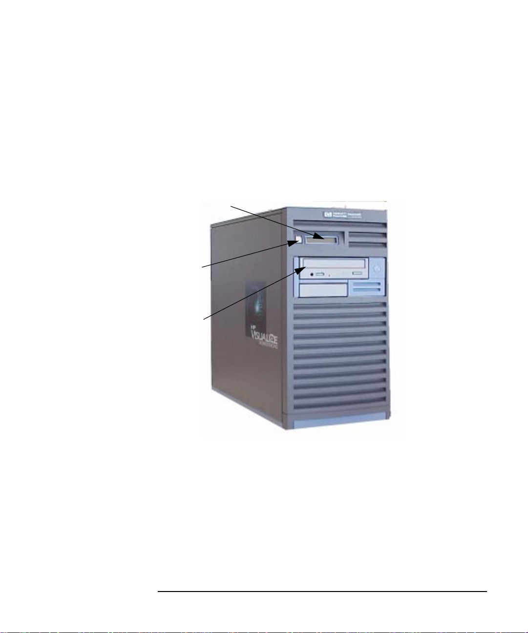
Figure 1-1 shows the components that are located on the front panel of
the B2000 workstation. The following subsections describe the system
LCD, power switch, and the internal storage devices (including the
standard CD drive and optional floppy disk drive) that are located on the
front panel.
Figure 1-1 Front Panel Components
System LCD
Power
Switch
CD Drive

20 Chapter1
Overview
Product Information
System LCD
The Liquid Crystal Display (LCD) is located on the left side of the front
panel. The LCD has a 2-line display, with up to 16 characters per line.
The LCD displays progress messages and error messages. Error
messages, known as chassis codes, are used in troubleshooting. The
symbols in Figure 1-2 appear in the LCD, representing different system
activities.
Figure 1-2 LCD Symbols
For more information, see the “LCD Information” section in Chapter 6.
Power Switch
The power switch is also located on the left side of the front panel. Use
the power switch to power your workstation on and off.
When you press the power switch to power off your workstation, the
operating system executes an automatic shutdown -q command. This
prevents any damage to programs and data on your system disk.
Pressing the power switch on again automatically boots up the HP-UX
operating system, if your system has been configured to auto boot. For
information on setting auto boot, see “Setting the Auto Boot and Auto
Search Flags” in Chapter 5.
Operating system running
Disk access in progress
Network receive in progress
Network transmit in progress

Chapter 1 21
Overview
Product Information
Internal Storage Devices
The B2000 workstation has one 9 GB 7200 RPM Ultra2 Wide
Low-Voltage Differential (LVD) SCSI hard disk drive as a standard
component. Optionally, the workstation also supports a second 9 GB
7200 RPM Ultra2 Wide LVD SCSI hard disk drive.
In addition, the B2000 workstation has one ATAPI CD drive as a
standard component. Optionally, the workstation also supports one
3.5-inch floppy disk drive.
NOTE You cannot have two CD drives nor two floppy disk drives, since the
B2000 workstation only supports one each of these devices.
Figure 1-1 on page 19 shows the workstation with one CD drive
installed. See Chapter 2 for detailed descriptions of the CD drive controls
and Chapter 3 for detailed descriptions of the floppy disk drive controls.

22 Chapter1
Overview
Product Information
Rear Panel Components
This section describes the following components on the rear panel of the
B2000 workstation:
• Monitor connector
• Serial (RS-232) connectors
• USB (Universal Serial Bus) connectors
• LAN (Ethernet IEEE 802.3, RJ45 Twisted Pair 10/100 BaseT)
connector
• Parallel (IEEE 1284) connector
• Audio connectors (Line In, Line Out, Microphone In, and Headphones
Out)
• TOC (Transfer Of Control) button
• I/O slots
• Power cord connector
• Security loop
NOTE To maintain FCC/EMI compliance, verify that all cables are fully seated
and properly fastened.
Chapter 1 23
Overview
Product Information
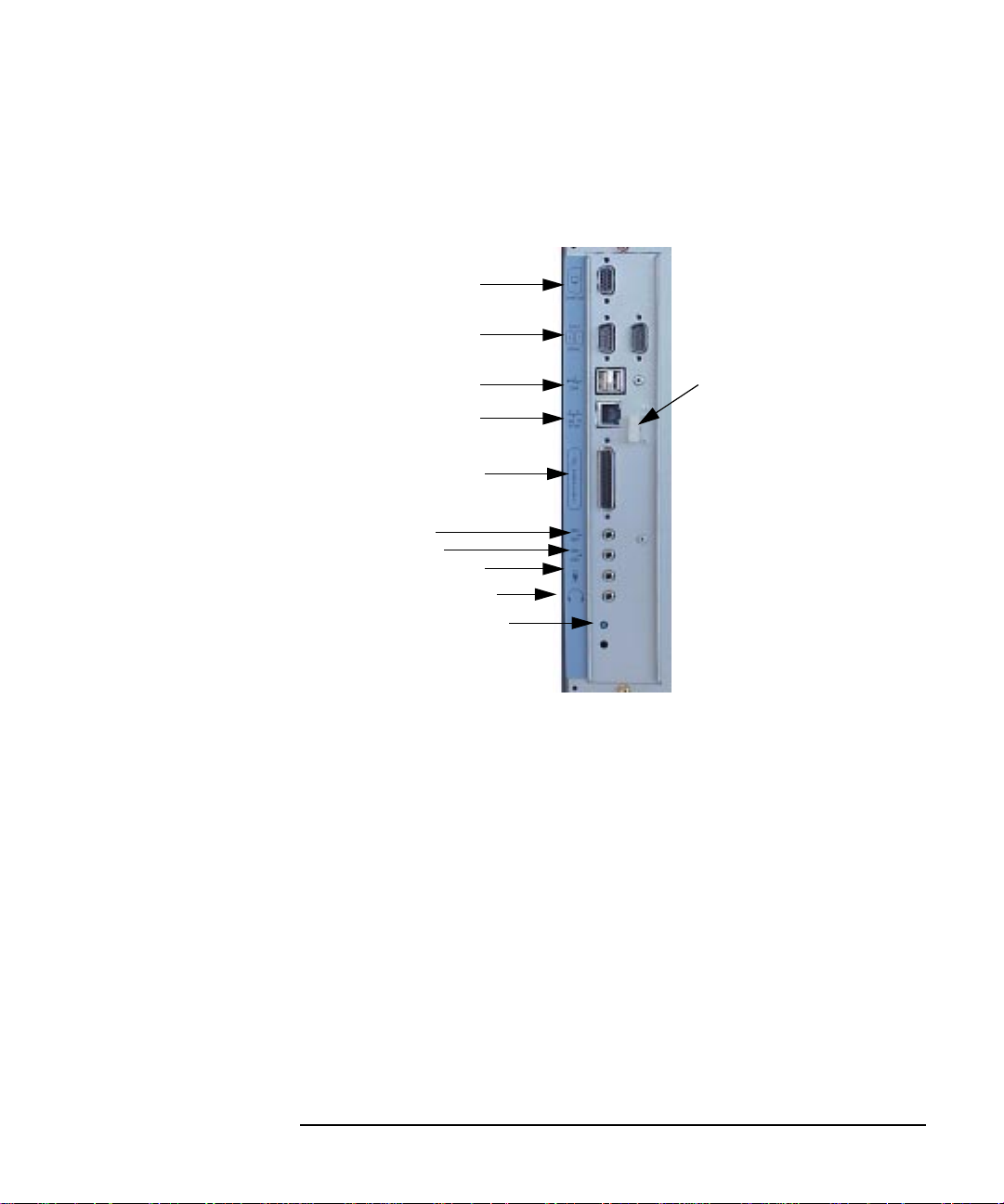
Figure 1-3 shows the locations of the components on the rear panel of the
B2000 workstation.
Figure 1-3 Rear Panel Components
Monitor Connector
The B2000 workstation has an integrated HP VISUALIZE fxe graphics
chip on the system board. Thus, the monitor connector on the rear panel
of the workstation connects your monitor to this graphics chip on the
system board.
Monitor Connector
Two Serial Connectors
Two USB Connectors
LAN Connector
Parallel Connector
Four Audio Connectors:
Line In
Line Out
Microphone In
Headphones Out
TOC Button
USB
Cable Clip

24 Chapter1
Overview
Product Information
Serial Connectors
You can attach a variety of pointing devices (such as a mouse or
trackball) or peripheral devices (including printers, plotters, modems,
and scanners) to the two Serial Input/Output (SIO) RS-232 ports on the
rear panel of this workstation. Consult the documentation that
accompanies each pointing device or peripheral device for specific
information concerning its use.
The SIO ports are programmable, allowing functions such as bit rate,
character length, parity, and stop bits to be set. You can set these by
using the HP-UX System Administration Manager (SAM) utility, or by
selecting a system special device file with the functions already
programmed. The SIO ports are used as an interface for serial
asynchronous devices to the CPU.
Table 1-2 shows the SIO connector pin listings. The serial connectors are
9-pin D-sub connectors. Signal names are those specified in the EIA
RS-232 standard.
Table 1-2 Serial I/O Pins
Pin No. Signal Description
1 DCD Data Carrier Detect
2 RXD Receive Data
3 TXD Transmit Data
4 DTR Data Terminal Ready
5 GND Ground
6 DSR Data Set Ready
7 RTS Request To Send
8 CTS Clear To Send
9 RI Ring Indicator

Chapter 1 25
Overview
Product Information
USB Connectors
The USB connectors located on the rear panel of the workstation provide
and interface for the keyboard ad mouse to the system. These USB
connectors support only the HP keyboard, HP mouse and USB hub. The
keyboard and mouse may be plugged into either USB connector on the
rear of the workstation or plugged into the USB hub. No other USB
configuration is currently supported. Consult the documentation that
accompanies each input device for specific information concerning its
use.
For more information on USB, see the Universal Serial Bus website at
the following URL:
http://www.usb.org
The following subsections briefly describe each of the three USB devices
you can connect to the B2000 workstation’s USB connectors. The mouse
and keyboard were shipped with your workstation, and the USB hub can
be ordered separately.
CAUTION Usage of devices other than USB specification may result in
unpredictable functionality and inferior performance of the B2000
workstation.
NOTE The USB cable clipon the rear of the chassis provides strain relief for the
USB cables. Open the cable clip, loop the cables through the clip and
snap it closed to secure the USB cables. See Figure 1-3 on page 23.
HP USB Keyboard
The HP USB keyboard provides the standard keycaps found on most PC
keyboards.
NOTE The USB keyboard and mouse may be plugged into either USB connector
on the rear of the B2000 workstation.

26 Chapter1
Overview
Product Information
HP USB Three Button Mouse
For general information on the various cursor shapes associated with
different areas of HP CDE while using a mouse, see the Using Your HP
Workstation manual.
LAN Connector
Your workstation has one built-in, Ethernet IEEE 802.3, RJ45 Twisted
Pair (TP) connector for 802.3 (Ethernet) or 10/100 BaseT networking.
Your workstation will automatically select the correct network setting.
Parallel Connector
The 25-pin HP Parallel I/O interface uses IEEE 1284 I/O interface
protocols to support peripheral devices such as printers and plotters.
consult the documentation that accompanies each parallel peripheral
device for specific information concerning its use.
Audio Connectors
Your workstation has audio-input and -output capability through
external input and output connectors on the rear panel and through an
internal speaker. As shown in Figure 1-4 on the next page, the
workstation’s rear panel contains four audio connectors: Line In, Line
Out, Microphone In, and Headphones Out.
Figure 1-4 Audio Connectors
Line In
Line Out
Microphone In
Headphones Out

Chapter 1 27
Overview
Product Information
The audio connectors are standard stereo audio mini-jacks.
Hewlett-Packard recommends using gold-plated plugs available through
audio retailers for best quality recording and playback through the
external connectors. The audio electrical specifications are summarized
in Table 1-3.
Table 1-3 Audio Electrical Specifications
Frequency Response 25 Hz to 20 kHz
Input Sensitivity/Impedance:
Line in
Microphone in
2.8Vp-p/10Kohm
40mVp-p/47Kohm
Maximum Output Level/Impedance:
Line out
Headphone out
2.8Vp-p/920ohm
5.6Vp-p/110ohm

28 Chapter1
Overview
Product Information
TOC Button
You can press the TOC (Transfer Of Control) button on the rear panel to
interrupt the system.
I/O Slots
The four I/O slots located on the rear panel are PCI (Peripheral Connect
Interface) slots, which you can use for add-on I/O interface cards. There
are two PCI-2X slots and two PCI-1X slots, which are defined as follows:
Slot 1: 64-bit PCI-2X at 5V, 33 MHz
Slot 2: 64-bit PCI-2X at 5V, 33 MHz
Slot 3: 32-bit PCI-1X at 5V, 33 MHz
Slot 4: 32-bit PCI-1X at 5V, 33 MHz
For more information, see the “I/O Cards” on page 81 in Chapter 4.
Power Cord Connector
Plug the workstation’s power cord into the power cord connector to
provide AC power to the workstation.
Chapter 1 29
Overview
Product Information
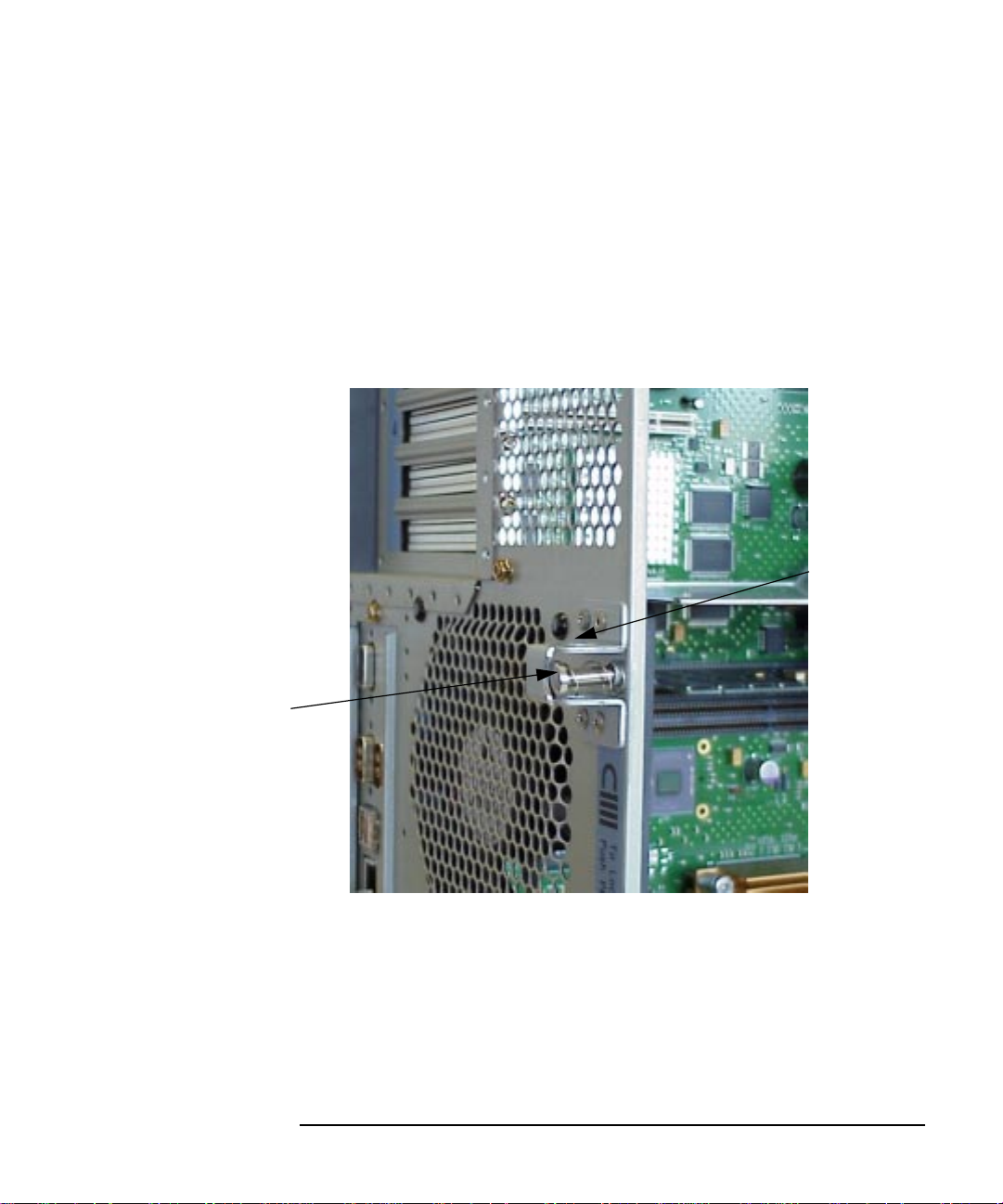
Security Loop
There is also a security loop on the rear panel of the B2000 workstation.
The security loop allows you to lock the workstation’s left side panel,
thus securing the internal components of your workstation. Figure 1-5
provides a view of the security loop.
Figure 1-5 Security Loop Components
Security
Loop Pin
Hole
Security Loop Pin
and Spring
30 Chapter1
Overview
Product Information
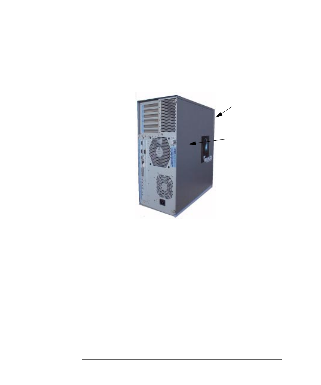
To lock your workstation’s left side panel, follow these steps:
1. Make sure the workstation’s left side panel is closed. See Figure 1-6.
Figure 1-6 Closed Left Side Panel
2. Push the security loop’s pin into the security loop pin hole, and insert
the padlock’s latch through the holes at the top and bottom of the
security loop. This locks the left side panel.
3. Lock the padlock. Your workstation’s left side panel is now secure.
Workstation’s
Front Panel
Left Side Panel
(using the front
panel as
reference)
 Loading...