


 Loading...
HP UPS Network Module
User Guide
Abstract
This document includes installation, configuration, and operation information for the HP UPS Network Module. This document is for the person who installs and maintains power products. HP assumes you are qualified in the servicing of high-voltage equipment and trained in recognizing hazards in products with hazardous energy levels.
Part Number: 637918-003
June 2013
Edition: 3
© Copyright 2011, 2013 Hewlett-Packard Development Company, L.P.
The information contained herein is subject to change without notice. The only warranties for HP products and services are set forth in the express warranty statements accompanying such products and services. Nothing herein should be construed as constituting an additional warranty. HP shall not be liable for technical or editorial errors or omissions contained herein.
Confidential computer software. Valid license from HP required for possession, use or copying. Consistent with FAR 12.211 and 12.212, Commercial Computer Software, Computer Software Documentation, and Technical Data for Commercial Items are licensed to the U.S. Government under vendor’s standard commercial license.
Microsoft® and Windows® are U.S. registered trademarks of Microsoft Corporation. Google™ is a trademark of Google Inc.

Contents |
|
Introduction.................................................................................................................................. |
6 |
Overview ................................................................................................................................................. |
6 |
Features ......................................................................................................................................... |
6 |
HP Power Protector overview ...................................................................................................................... |
7 |
Supported hardware configurations ............................................................................................................. |
7 |
Configuration A .............................................................................................................................. |
7 |
Configuration B............................................................................................................................... |
8 |
Web interface requirements........................................................................................................................ |
9 |
Quick installation and setup overview ........................................................................................................ |
10 |
Component identification............................................................................................................. |
11 |
Front panel connectors and LED indicators.................................................................................................. |
11 |
Installing the HP UPS Network Module .......................................................................................... |
12 |
Precautions............................................................................................................................................. |
12 |
Required tools......................................................................................................................................... |
12 |
Installing the UPS Network Module............................................................................................................ |
12 |
Connecting the network cable................................................................................................................... |
13 |
Connecting the configuration cable ........................................................................................................... |
14 |
Launching a terminal emulation program.................................................................................................... |
14 |
Configuring the UPS Network Module network settings ................................................................................ |
15 |
HP UPS Network Module web interface ........................................................................................ |
16 |
HP UPS Network Module web interface overview........................................................................................ |
16 |
Accessing the web interface ..................................................................................................................... |
16 |
Browser security alert............................................................................................................................... |
17 |
Establishing a secure session for Internet Explorer .............................................................................. |
17 |
Establishing a secure session for Mozilla .......................................................................................... |
18 |
Establishing a secure session for Firefox ........................................................................................... |
18 |
Establishing a secure session for Google Chrome .............................................................................. |
19 |
Navigating the web interface.................................................................................................................... |
19 |
Views .................................................................................................................................................... |
19 |
Power Source screen...................................................................................................................... |
20 |
Manual Control screen................................................................................................................... |
25 |
Logs ...................................................................................................................................................... |
26 |
UPS Data Log screen...................................................................................................................... |
26 |
Event Log screen............................................................................................................................ |
28 |
System Log screen ......................................................................................................................... |
29 |
Settings.................................................................................................................................................. |
29 |
System Settings screen ................................................................................................................... |
30 |
Access Control screen .................................................................................................................... |
31 |
Network Settings screen ................................................................................................................. |
32 |
Time Settings screen....................................................................................................................... |
34 |
Shutdown Parameters screen........................................................................................................... |
35 |
Scheduled Shutdown screen............................................................................................................ |
39 |
SNMP Settings screen .................................................................................................................... |
40 |
Notified Applications screen ........................................................................................................... |
42 |
Contents |
3 |
Email Notification screen................................................................................................................ |
44 |
Firmware Upload screen ................................................................................................................ |
47 |
HP UPS Network Module Configuration Menu ............................................................................... |
48 |
HP UPS Network Module Configuration Menu overview............................................................................... |
48 |
Accessing the Service Menu ..................................................................................................................... |
48 |
Navigating the menus.............................................................................................................................. |
48 |
Main menu............................................................................................................................................. |
48 |
Reset submenu .............................................................................................................................. |
49 |
Network Configuration submenu ..................................................................................................... |
49 |
Systems Insight Manager integration ............................................................................................. |
50 |
Systems Insight Manager overview ............................................................................................................ |
50 |
Discovering the UPS Network Module........................................................................................................ |
51 |
Configuring HP SIM to receive traps .......................................................................................................... |
52 |
Configuring the UPS Network Module to send traps to HP SIM...................................................................... |
52 |
Optional power monitoring using SNMP ....................................................................................... |
53 |
SNMP monitoring.................................................................................................................................... |
53 |
Configuration parameters ............................................................................................................ |
54 |
Shutdown parameters .............................................................................................................................. |
54 |
Updating the firmware ................................................................................................................ |
57 |
Updating the firmware overview................................................................................................................ |
57 |
Firewall configuration.................................................................................................................. |
58 |
Configuring the firewall on Windows......................................................................................................... |
58 |
Security considerations ................................................................................................................ |
67 |
Security considerations overview ............................................................................................................... |
67 |
Alert messages ........................................................................................................................... |
68 |
UPS alarms............................................................................................................................................. |
68 |
SNMP trap codes ....................................................................................................................... |
72 |
SNMP trap codes.................................................................................................................................... |
72 |
Specifications............................................................................................................................. |
75 |
Technical characteristics........................................................................................................................... |
75 |
Default parameters .................................................................................................................................. |
76 |
Troubleshooting .......................................................................................................................... |
78 |
Client communication failure with HP UPS Network Module in a VMware operating system.............................. |
78 |
Client server is not restarting..................................................................................................................... |
78 |
Clients cannot communicate with UPS after swapping HP UPS Network Module with another UPS..................... |
78 |
Failure to communicate with the serial or USB ports ..................................................................................... |
78 |
Forgot login password ............................................................................................................................. |
78 |
UPS Network Module fails to boot after upgrading the firmware ................................................................... |
79 |
UPS is not powered on after a scheduled shutdown ..................................................................................... |
79 |
Support and other resources ........................................................................................................ |
80 |
Before you contact HP.............................................................................................................................. |
80 |
HP contact information............................................................................................................................. |
80 |
Regulatory compliance notices ..................................................................................................... |
81 |
Safety and regulatory compliance ............................................................................................................. |
81 |
Warranty information .............................................................................................................................. |
81 |
Contents |
4 |
Acronyms and abbreviations........................................................................................................ |
82 |
Documentation feedback ............................................................................................................. |
84 |
Index......................................................................................................................................... |
85 |
Contents 5

Introduction
Overview
The HP UPS Network Module works with HP Power Protector software to monitor, manage, and protect power environments. The UPS Network Module can send email and text notification messages to configured recipients and alert traps to specified SNMP management programs, such as HP Systems Insight Manager, or used as a stand-alone management system.
NOTE: Text notification on mobile phones require the use of an external provider that converts emails into text notifications on mobile phones.
The HP UPS Network Module includes:
•HP UPS Network Module web interface—A graphical interface that is accessed with a web browser
•HP UPS Network Module Configuration Menu (on page 48)—A text-based menu that is accessed through a terminal emulation session
For a detailed list of supported UPSs, see the HP website (http://www.hp.com/go/rackandpower).
Features
The UPS Network Module is a minislot card that requires UPSs equipped with a minislot. The UPS Network Module:
•Monitors the status, performs UPS diagnostics, and transmits periodic reports.
•Manages independent UPS load segments to provide separate power control of connected equipment.
•Prioritizes the timing of equipment shutdown, and reboots connected equipment by load segment.
•Delays restart by load segment after a power outage to sequence the startup of system components.
•Shuts down and reboots the UPS and attached equipment, based on a user-specified schedule.
•Sends customized email, broadcast, and text notification messages and SNMP traps.
•Displays logs for analysis.
•Includes enhanced HP SIM integration.
•Includes multi-language support.
•Supports IPv4 and IPv6.
•Provides automatic date and time adjustment through an NTP server.
•Supports fast Ethernet 10/100 MB compatibility with auto-negotiation on the RJ-45 network port.
•Allows for installation while the UPS is online, to maintain the highest system availability.
When used in conjunction with the UPS Network Module, HP Power Protector:
•Manages an automatic, graceful shutdown of attached equipment during a utility power failure.
•Issues computer commands at power failure.
Introduction 6

•Supports network-attached server communications.
•Supports a customizable Events script.
•Provides redundancy feature support.
•Is compatible with the R1500 G3 UPS, R/T3000 G2 UPS, R5000 UPS and R7000 UPS.
For more information, see the HP Power Protector User Guide on the HP website (http://www.hp.com/go/rackandpower).
HP Power Protector overview
HP Power Protector is a UPS software management application that can be used standalone without the UPS Network Module in an Administrator/Client configuration or with the UPS Network Module in a Client configuration only.
The HPPP Client runs on a local or network server and allows the UPS Network Module to gracefully shut down the operating system of that server and optionally run a script during power failure. Install the HPPP Client on any machine that is powered by the UPS and any machine that the UPS Network Module uses to initiate a shutdown command.
For more information, see the HP Power Protector User Guide on the HP website (http://www.hp.com/go/rackandpower).
You can also use a third-party SNMP manager to monitor the power protection. For more information, see "SNMP monitoring (on page 53)."
Supported hardware configurations
The UPS Network Module can be attached in any of the following configurations:
•Configuration A (on page 7)—One or more HPPP Clients are powered by a UPS and communicate with one UPS Network Module over the network.
•Configuration B (on page 8)—One or more HPPP Clients are redundantly powered by two UPSs and communicate with two UPS Network Modules over the network.
Configuration A
This figure illustrates one or more HPPP Clients are powered by a UPS and communicates with one UPS Network Module over the network to begin a graceful shutdown in the event of a power failure or other configured shutdown events.
NOTE: Up to 35 HPPP Clients can be managed by one HP UPS Network Module.
Introduction 7
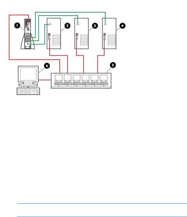
Item |
Description |
|
|
1 |
UPS with an HP UPS Network Module |
2 |
HPPP Client server |
3 |
HPPP Client server |
|
|
4 |
HPPP Client server |
5 |
Network |
6 |
Remote workstation browsing into the HP UPS Network |
|
Module or HPPP Client over the network |
|
|
Green |
Power connection |
Red |
Communication path |
Configuration B
This figure illustrates one or more HPPP Clients are redundantly powered by two UPSs and communicate with two UPS Network Modules over the network to begin a graceful shutdown in the event of a power failure or other configured shutdown events.
NOTE: Up to 35 HPPP Clients can be managed by one HP UPS Network Module.
Introduction 8

Item |
Description |
|
|
1 |
UPS with an HP UPS Network Module |
2 |
UPS with an HP UPS Network Module |
3 |
HPPP Client server |
4 |
HPPP Client server |
5 |
Network |
6 |
Remote workstation browsing into the UPS Network |
|
Module or HPPP Client over the network |
|
|
Green |
Power connection |
Red |
Communication path |
Web interface requirements
The following table lists the minimum requirements necessary to operate the UPS Network Module web interface.
Software |
Browser |
|
|
|
|
Internet Explorer |
• Windows Internet Explorer 7 |
|
|
• Windows Internet Explorer 8 |
|
|
• Windows Internet Explorer 9 |
|
|
|
|
Mozilla |
HP-UX Mozilla 1.4.x |
|
Firefox |
• Linux Firefox 3.5.x (native to Linux version) |
|
|
• |
Windows Firefox 3.6.15 |
|
• |
Windows Firefox 4 |
|
|
|
Chrome 10.x |
||
Introduction 9
Quick installation and setup overview
1.Install the UPS Network Module ("Installing the UPS Network Module" on page 12) and configure the network settings.
2.Access the web interface.
3.Configure the power fail settings using the Shutdown Parameters screen (on page 35).
4.(optional) Configure additional settings using the menus under Settings (on page 29).
5.Install and configure the HPPP Client on all servers to be protected by the UPS. After all Clients are configured at the servers, they are automatically added by the UPS Network Module and appear on the Notified Applications screen (on page 42).
For more information, see the HP Power Protector User Guide on the HP website (http://www.hp.com/go/rackandpower).
Introduction 10
Component identification
Front panel connectors and LED indicators
Item |
Connector/LED |
Description |
|
|
|
1 |
Network connector |
Ethernet port |
2 |
Network Activity LED |
• Off—UPS Network Module not connected to the network |
|
|
• Solid green—UPS Network Module connected to the network, |
|
|
but no activity detected |
|
|
• Flashing green—UPS Network Module connected to the network |
|
|
and sending or receiving data |
|
|
|
3 |
Network Speed LED |
• Off—Port operating at 10 Mb/s |
|
|
• Solid orange—Port operating at 100 Mb/s |
|
|
|
4 |
Settings/AUX connector |
Configuration port |
5 |
UPS Data LED |
• Off—UPS Network Module starting |
|
|
• Solid green—UPS Network Module communicating with UPS |
|
|
• Flashing green—Normal operation (communication link |
|
|
established) |
|
|
|
6 |
Configuration Menu LED |
• Off—Configuration menu activated |
|
|
• Solid orange—Normal operation (Configuration menu not |
|
|
activated) |
|
|
|
Component identification 11

Installing the HP UPS Network Module
Precautions
See the Important Safety Information guide (included in the UPS kit) before installing this product.
WARNING: A risk of personal injury from electric shock and hazardous energy levels exists. The installation of options and routine maintenance and service of this product must be performed by individuals who are knowledgeable about the procedures, precautions, and hazards associated with AC power products.
Required tools
No. 2 Phillips screwdriver
Installing the UPS Network Module
NOTE: It is not necessary to power down the UPS before installing the UPS Network Module.
1.Remove the two screws securing the UPS option slot cover plate and slide the plate out.
2.Install the UPS Network Module along the alignment channels in the option slot.
Installing the HP UPS Network Module 12
3.If the UPS is powered up, you can be sure that the UPS Network Module is seated properly and communicating with the UPS by verifying that the UPS Data LED illuminates solid green, and then flashes regularly after 2 minutes.
4.Secure the UPS Network Module using the two screws you removed in step 1.
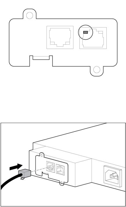
Connecting the network cable
Connect a standard Ethernet cable between the network connector on the UPS Network Module and a network jack.
This connection is used to access the UPS Network Module remotely through the web interface. The UPS Network Module also uses the network connection to communicate to the configured HPPP Clients and to facilitate SNMP-based monitoring.
Installing the HP UPS Network Module 13
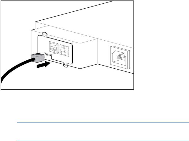
Connecting the configuration cable
1.Connect the DB-9 connector on the DB-9 to RJ-45 cable to a serial connector on the host computer.
2.Connect the RJ-45 connector on the DB-9 to RJ-45 cable to the Settings/AUX connector on the UPS Network Module.
This connection is used to access and configure the UPS Network Module network settings locally through a terminal emulation program.
Launching a terminal emulation program
NOTE: HyperTerminal is the serial communication program provided with Microsoft® Windows® and is used in this section as an example for setting up a terminal emulation session. If you are using another utility, the steps might be different.
1.Be sure that the UPS is powered on.
2.On the host computer, click Start, and select Programs>Accessories>Communications>HyperTerminal.
The Connection Description window appears.
3.Enter a description, select an icon for the connection, and then click OK. The Connect To window appears.
4.Select the serial connector on the host computer to which the DB-9 to RJ-45 adapter is attached, and then click OK. The COM Properties window appears.
5.Select the following parameter values, and then click OK. o Bits per second—9600
o Data bits—8
o Parity—None o Stop bits—1
o Flow control—None
Installing the HP UPS Network Module 14

Configuring the UPS Network Module network settings
On the terminal emulation session screen running on the host computer:
1.Press any key. The initialization process completes, and then you are prompted to enter the password.
2.At the prompt, enter admin. The HP UPS Network Module Configuration Menu appears.
Use the HP UPS Network Module Configuration Menu to configure the minimum settings required to access the UPS Network Module remotely.
IMPORTANT: The IP address assigned to the UPS Network Module must be fixed. If the IP address changes:
•The HPPP Client loses communication with the UPS Network Module.
•You can lose track of the UPS Network Module URL.
3.If your network is configured with a DHCP server, the network settings are automatically assigned. To view the settings:
a.On the Main menu, enter 2 to display the Network Configuration submenu.
b.Enter 1 to view the network settings.
c.Record the IP address.
d.Enter 0 to return to the Main menu.
e.Enter 0 to exit the Configuration Menu. The UPS Network Module is operational.
NOTE: You can configure the DHCP server to permanently assign the same IP address for each UPS Network Module using the MAC address of the card.
4.If your network is not configured with a DHCP server:
a.On the Main menu, enter 2 to display the Network Configuration submenu.
b.Enter 2 to modify the network settings.
c.Follow the on-screen instructions to enter the static IP parameters. A Done message appears when the parameters are saved.
d.Enter 0 to return to the Main menu.
e.Enter 1 to reset the UPS Network Module, and then enter 2 to restart the UPS Network Module with the new IP settings.
Installing the HP UPS Network Module 15

HP UPS Network Module web interface
HP UPS Network Module web interface overview
The web interface graphically displays various measurements and warning and alarm messages from the UPS Network Module. Also, system values and power fail settings can be configured through the web interface and saved to the UPS Network Module.
NOTE: Network settings included on the UPS Network Module web interface can also be configured using the HP UPS Network Module Configuration Menu (on page 48).
Accessing the web interface
CAUTION: It is highly recommended that browser access to the UPS Network Module is isolated from outside access using a firewall or isolated network.
To access the web interface:
1.On a network computer, launch a supported browser. The browser window appears.
2.In the URL field, enter: http://xxx.xxx.xxx.xxx
-or- https://xxx.xxx.xxx.xxx
where xxx.xxx.xxx.xxx is the static IP address of the UPS Network Module. The login screen appears.
3.Enter the user name in the User Name field. The default user name is admin.
4.Enter the password in the Password field. The default password is admin.
HP UPS Network Module web interface 16
5.Click Sign In. The HP UPS Network Module web interface appears.
Browser security alert
Secure browsing requires the use of SSL. SSL is a protocol layer that lies between HTTP and TCP that provides secure communication between a server and a client, and is designed to provide privacy and message integrity. SSL is commonly used in web-based transactions to authenticate the web server, which indisputably identifies the server to the browser. SSL also provides an encrypted channel of communication between the server and the browser. The encrypted channel ensures the integrity of the data between the web server and the browser, so that data can neither be viewed nor modified while in transit. The UPS Network Module uses a system generated and unique key.
An integral part of SSL is a security certificate, which identifies the UPS Network Module. If your browser displays a security alert when browsing to the UPS Network Module, it can be for one of several reasons:
•The certificate is untrusted, meaning it was signed by a certifying authority that is unknown to your browser.
•The certificate has expired or is not yet valid. This condition can occur if you issue your own certificate and it has expired.
•The name on the certificate does not match the name of the site in the browser address field.
For more information about security considerations, see "Security considerations overview (on page 67)."
Establishing a secure session for Internet Explorer
The first time you browse to the UPS Network Module, the Secure Session screen appears. To ensure a secure connection, verify that you are browsing to the desired UPS Network Module:
1.Click View Certificate.
2.Verify that the name in the Issued To field is the name of your UPS Network Module.
HP UPS Network Module web interface 17

3.Perform any other steps necessary to verify the identity of the UPS Network Module.
CAUTION: If you are not sure this is the desired UPS Network Module, do not proceed. Importing a certificate from an unauthorized source relays your login credentials to that unauthorized source. Exit the certificate window and contact the system administrator.
After verifying the UPS Network Module, do one of the following:
•Import the certificate and proceed.
a.Click View Certificate. The certificate appears.
b.Click Install Certificate. The Certificate Import wizard runs.
c.Click Next. The Certificate Store screen appears.
d.Select Automatically select the certificate store based on the type of certificate, and then click Next.
e.Click Finish. A message appears, asking for verification of the root store.
f.Click Yes.
•Proceed without importing the certificate by clicking Yes at the Security Alert window. You continue to receive the Security Alert each time you log in until you import the certificate. Your data is still encrypted.
•Exit and import the certificate into your browser from a file provided by the administrator.
a.Click No at the Security Alert window.
b.Obtain an exported certificate file from the administrator.
NOTE: If using Internet Explorer, you can manually import the file into the browser by clicking
Tools>Internet Options>Content>Certificates>Import.
Establishing a secure session for Mozilla
The first time you browse to the UPS Network Module, the Secure Session screen appears. To ensure a secure connection, verify that you are browsing to the desired UPS Network Module:
1.Click Examine Certificate.
2.Verify that the name in the Issued To field is the name or IP address of your UPS Network Module.
3.Perform any other steps necessary to verify the identity of the UPS Network Module.
4.After verifying the UPS Network Module, do one of the following:
a.Click either Accept this certificate permanently or Accept this certificate temporarily for this session.
b.Click OK.
NOTE: If using Mozilla, you can manually import the file into the browser by clicking
Edit>Preferences>Privacy & Security>Certificates>Manage Certificates>Authorities>Import.
Establishing a secure session for Firefox
The first time you browse to the UPS Network Module, the Secure Session screen appears. To ensure a secure connection, verify that you are browsing to the desired UPS Network Module:
1.Click Examine Certificate.
2.Verify that the name in the Issued To field is the name or IP address of your UPS Network Module.
3.Perform any other steps necessary to verify the identity of the UPS Network Module.
HP UPS Network Module web interface 18
4.After verifying the UPS Network Module, do one of the following:
a.Click either Accept this certificate permanently or Accept this certificate temporarily for this session.
b.Click OK.
NOTE: If using Firefox, you can manually import the file into the browser by clicking
Edit>Preferences>Advanced>Security>View Certificates>Authorities>Import.
Establishing a secure session for Google Chrome
To establish a secure session:
1.Browse to the UPS Network Module through a secure connection. The certificate appears with a warning.
2.Click Proceed anyway, and then login to the UPS Network Module web interface.
Navigating the web interface
The web interface is divided into two frames:
•Menu tree—Contains a list of menu options on the left side of the screen
•Main frame—Contains the various interface screens based on the menu option selected in the left navigation frame
Click Help to view online help.
Views
Menu options listed under Views include:
HP UPS Network Module web interface 19

•Power Source ("Power Source screen" on page 20)
•Manual Control ("Manual Control screen" on page 25)
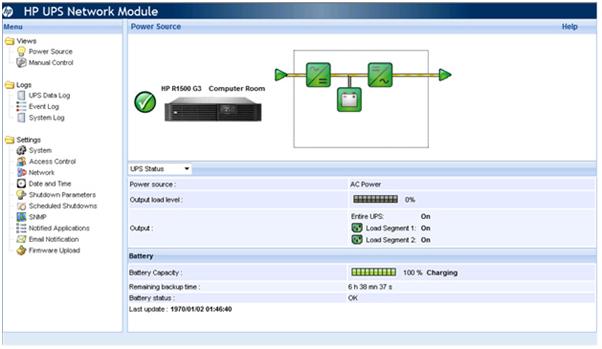
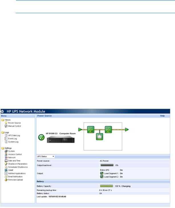
Power Source screen
Click Power Source in the menu tree to display the Power Source screen. This screen displays the overall status of the UPS. The status information refreshes every 10 seconds.
The top part of the screen displays the following UPS information:
•UPS status icon—The current UPS status
Status icon |
Description |
|
|
|
Green—Normal operation |
|
|
|
Red—Alarm present |
|
Click the icon to display the UPS alarms. |
|
|
|
Gray—UPS communication loss |
|
|
•UPS name—The name of the UPS
The UPS name is the generic name of the UPS model, and this name displays throughout the interface.
•UPS location—The location of the UPS
The UPS location can be modified on the System Settings screen (on page 30).
•UPS graphical representation—A graphical representation of the UPS model
•UPS operating mode diagram—An animated graphical representation of the UPS operating mode showing the main UPS components and the electrical flow powering the load
If communication with the UPS is lost, the diagram appears gray. Diagrams do not display for line-interactive UPSs.
HP UPS Network Module web interface 20
•UPS measurements—A popup box that displays UPS data details
Hover your mouse over an element in the UPS operating mode diagram to display UPS data details. UPS data is available for Normal mode, Battery mode, and Bypass mode. The available UPS data depends on the UPS range. Available UPS information includes:
o AC Output Voltage—The UPS output voltage o AC Output Current—The UPS output current
o AC Output Frequency—The UPS output frequency
o Load Level—The percentage of load at the UPS output o Apparent Power—The UPS apparent power
o Active Power—The UPS active power
The following table describes the possible UPS operating mode diagrams.
Diagram |
UPS operating |
|
mode |
|
|
|
UPS with automatic |
|
bypass |
UPS without automatic bypass
The following table describes the possible diagram elements.
Diagram element |
Description |
|
|
AC Normal Input |
|
|
Green—In tolerance |
|
|
|
Gray—Out of tolerance |
|
|
AC Normal Flow |
|
HP UPS Network Module web interface 21

Diagram element |
Description |
|
|
|
Yellow—AC to DC converter powered by |
|
normal AC |
|
|
|
Gray—AC to DC converter not powered by |
|
normal AC |
|
|
AC to DC Converter |
|
|
Green—Powered |
|
|
|
Gray—Not powered |
|
|
|
Red—Internal failure |
|
|
Battery |
|
|
Green—Remaining capacity > 50% |
|
|
|
Orange—Remaining capacity < 50% |
|
|
|
Red—Battery to be checked (battery test |
|
result) |
|
|
Battery Output Flow |
|
|
|
|
Yellow—AC to DC converter powered by |
|
battery |
|
|
|
Gray—AC to DC converter not powered by |
|
battery |
|
|
DC to AC Converter Input Flow |
|
|
|
|
Yellow—Energy flow present |
|
|
|
Gray—No energy flow |
|
|
DC to AC Converter |
|
|
|
|
Green—Powered |
|
|
|
Gray—Not powered |
|
|
|
Red—Internal failure |
|
|
DC to AC Converter Output |
|
|
|
|
Yellow—Energy flow present |
|
|
|
Gray—No energy flow |
|
|
AC Bypass Input |
|
|
|
|
Green—In tolerance |
|
|
|
Red—Out of tolerance |
|
|
AC Automatic Bypass Flow |
|
|
|
HP UPS Network Module web interface 22

Diagram element |
Description |
|
|
|
Yellow—Energy flow present |
|
|
|
Gray—No energy flow |
|
|
AC Automatic Bypass Status |
|
|
|
|
Green—Powered |
|
|
|
Gray—Not powered |
|
|
|
Red—Internal failure |
|
|
AC Output Flow |
|
|
|
|
Yellow—Energy flow present |
|
|
|
Gray—No energy flow |
|
|
AC Output |
|
|
|
|
Green—Load protected |
|
|
|
Red—Load not protected |
|
|
The bottom part of the screen displays various tables containing UPS information. The table that displays depends on your selection in the pull-down menu. Available options include:
•UPS Status ("UPS Status table" on page 23)—Provides essential information about the power status of the UPS
•UPS Alarms ("UPS Alarms table" on page 24)—Displays a list of current alarms
•About your UPS ("About your UPS table" on page 24)—Provides information about the model range and software version of the UPS and the UPS Network Module
UPS Status table
The UPS Status table displays the following basic information about power and output:
•Power source—Indicates whether the UPS is on utility power or running on the UPS battery
•Output load level—The power percentage used at the UPS output
•Output—Indicates whether the individual UPS outputs are protected o Entire UPS—Indicates whether the UPS is powered on
o Load segment 1 and Load segment 2—Indicates whether the controlled load segments (if available) are powered
A green outlet icon (
 ) indicates that the load segment is on. A red outlet icon (
 ) indicates that the load segment is off. A gray outlet icon (
 ) indicates that the load segment status is unknown.
•Battery capacity—The remaining percentage of battery charge and the battery status: o Charging—Utility power is present and the battery charge is in progress
o Discharging—The UPS is operating on battery power
HP UPS Network Module web interface 23

oFault—The battery is faulty
•Remaining backup time—The estimated maximum battery backup time remaining before UPS shutdown
•Battery status—The result of the last automatic battery test run by the UPS:
oOK—The test completed correctly.
o NOK—The battery needs to be checked.
o Deactivated—The automatic battery test was not validated on the UPS. o Aborted—The automatic battery test was not completed on the UPS.
UPS Alarms table
The UPS Alarms table displays a list of current alarms with the following information:
• |
Alarm type—The date and time the alarm occurred |
|
• |
Alarm description—A description of the alarm |
|
• |
Severity—An icon that indicates the severity of the alarm |
|
|
|
|
Icon |
|
Alarm severity |
|
|
|
|
|
Normal |
|
|
|
|
|
Critical |
|
|
|
|
|
Warning |
|
|
|
|
|
Unknown |
|
|
|
For a complete list of UPS alarms, see "UPS alarms (on page 68)."
About your UPS table
The About your UPS table displays the following hardware and firmware information for the UPS and the UPS Network Module.
•UPS
o UPS Name—The name of the UPS
o UPS Part Number—The part number for the UPS
o UPS Serial Number—The serial number for the UPS
o UPS Firmware Revision—The firmware version for the UPS
o Communication Board Firmware Revision—The firmware version for the UPS internal communication board
•UPS Network Module
o Card Firmware Revision—The firmware version for the UPS Network Module o Card Part Number—The model number for the UPS Network Module
o Card Technical Level—The technical revision for the UPS Network Module
o Card Hardware Revision—The hardware version for the UPS Network Module o Card Serial Number—The serial number for the UPS Network Module
o Card Ethernet MAC Address—The MAC address for the UPS Network Module o Card Ethernet Speed—The port speed of the UPS Network Module
HP UPS Network Module web interface 24

Manual Control screen
Click Manual Control in the menu tree to display the Manual Control screen. This screen allows an administrator to execute shutdown and restart sequences for the UPS and its controlled load segments. To prevent data loss, configure the time required to shut down each registered server using the Shutdown Parameters screen (on page 35).
The status of each load segment is indicated by an icon. A green icon (
 ) indicates that the load segment
is on. A red icon ( ) indicates that the load segment is off. A gray icon (
 ) indicates that the load segment status is unknown.
IMPORTANT: The UPS has priority over the controlled load segments. Shutting down the UPS causes the load segments to shut down. Controlled load segments can only be restarted if the UPS is on.
Only users with administrator privileges can save command parameters and execute commands. To configure a command:
1.Select the command you want to run in the Control pull-down menu. Configured commands will not initiate until you click Execute.
o Safe power down—A shutdown sequence for the load segment is launched immediately. Connected equipment powers off, and then the load segment powers off.
o Safe power down & reboot—A sequence containing a shutdown command followed by a restart command for the load segment is launched immediately. Connected equipment powers off, and then the load segment powers off. The load segment restarts when the Toggle Duration time is reached.
o Immediate On—A restart sequence for the load segment is launched immediately. The load segment powers on, and then connected equipment powers on.
o Delayed, safe power down—A shutdown sequence for the load segment is launched when the Off Delay time is reached. Connected equipment powers off, and then the load segment powers off.
HP UPS Network Module web interface 25

oDelayed, safe power down & reboot—A sequence containing a shutdown command followed by a restart command for the load segment is launched when the Off Delay time is reached. Connected equipment powers off, and then the load segment powers off. The load segment restarts when the Toggle Duration time is reached.
oDelayed On—A restart sequence for the load segment is launched when the On Delay is reached. The load segment powers on, and then connected equipment powers on.
2.Configure the Off Delay time for delayed power down commands. Enter the number of seconds that should elapse between the time you execute the command and the shutdown sequence initiates.
3.Configure the Toggle Delay time for power down & restart commands. Enter the number of seconds that should elapse between the time the shutdown sequence completes and the restart sequence initiates.
4.Configure the On Delay time for power on commands. Enter the number of seconds that should elapse between the time you execute the command and the restart sequence initiates.
5.Click Save to save the Off Delay, Toggle Delay, and On Delay parameters.
6.Click Execute to initiate the configured commands.
Click Help to view online help.
Logs
Menu options listed under Logs include:
•UPS Data Log ("UPS Data Log screen" on page 26)
•Event Log ("Event Log screen" on page 28)
•System Log ("System Log screen" on page 29)
UPS Data Log screen
Click UPS Data Log in the menu tree to display the UPS Data Log screen. This screen displays a log of UPS data collected by the UPS Network Module. The frequency at which data is collected can be modified on the System Settings screen (on page 30). By default, data is collected every 60 seconds.
NOTE: In the UPS Data Log and the Event Log, the date and time stamps are converted to the local time zone.
HP UPS Network Module web interface 26

The following information is displayed for a single phase UPS:
•AC Input Voltage—The utility voltage supplying the UPS
•AC Input Frequency—The utility frequency supplying the UPS
•AC Output Voltage—The UPS output voltage
•AC Output Frequency—The UPS output frequency
•AC Output Power (kVA)—The UPS output power
•AC Output Load level (%)—The percentage of load at the UPS output
•Battery Capacity (%)—The percentage of battery charge available
•Battery Remaining time (min)—The estimated remaining backup time
NOTE: When the log reaches the maximum of 435 entries, new entries overwrite the oldest entries in the log.
On the screen:
•Click Save Log to download the log file (.csv) to your computer.
•Click Clear Log to clear the log files. Only users with administrator privileges can clear logs.
•Click Help to view online help.
HP UPS Network Module web interface 27
Loading...