


Officejet PRO X476
Table of contents
 Loading...
OFFICEJET PRO X476 AND X576
MFP SERIES
Troubleshooting Manual


HP Officejet Pro X476 and X576 MFP
Series
Troubleshooting Manual

Copyright and License
© 2013 Copyright Hewlett-Packard
Development Company, L.P.
Reproduction, adaptation, or translation
without prior written permission is
prohibited, except as allowed under the
copyright laws.
The information contained herein is subject
to change without notice.
The only warranties for HP products and
services are set forth in the express
warranty statements accompanying such
products and services. Nothing herein
should be construed as constituting an
additional warranty. HP shall not be liable
for technical or editorial errors or omissions
contained herein.
CN598-90006
Edition 2, 12/2013
Trademark Credits
®
Adobe
, Acrobat®, and PostScript® are
trademarks of Adobe Systems
Incorporated.
Intel® Core™ is a trademark of Intel
Corporation in the U.S. and other countries.
Java™ is a US trademark of Sun
Microsystems, Inc.
Microsoft®, Windows®, Windows® XP, and
Windows Vista® are U.S. registered
trademarks of Microsoft Corporation.
®
UNIX
is a registered trademark of The
Open Group.
ENERGY STAR and the ENERGY STAR
mark are registered U.S. marks.

Conventions used in this guide
TIP: Tips provide helpful hints or shortcuts.
NOTE: Notes provide important information to explain a concept or to complete a task.
CAUTION: Cautions indicate procedures that you should follow to avoid losing data or damaging
the product.
WARNING! Warnings alert you to specific procedures that you should follow to avoid personal
injury, catastrophic loss of data, or extensive damage to the product.
ENWW iii

iv Conventions used in this guide ENWW

Table of contents
1 Theory of operation ........................................................................................................................................ 1
Basic operation ..................................................................................................................................... 2
Function structure ................................................................................................................ 2
Operation sequence ............................................................................................................ 3
System control ...................................................................................................................................... 6
Formatter and data path ...................................................................................................... 6
Engine control ...................................................................................................................... 7
Pen interface (I/F) ................................................................................................................ 9
Power supply ..................................................................................................................... 10
Print subsystem .................................................................................................................................. 11
Printbar .............................................................................................................................. 11
Printbar air management system ....................................................................................... 13
Printbar lift .......................................................................................................................... 13
Ink cartridges ..................................................................................................................... 13
Optical scan carriage ......................................................................................................... 13
Print system operational states .......................................................................................... 13
Paper-handling system ....................................................................................................................... 16
Input trays .......................................................................................................................... 21
Paper path zones ............................................................................................................... 22
Servicing system ................................................................................................................................ 26
Service sled ....................................................................................................................... 27
Transmission system .......................................................................................................................... 28
Components ...................................................................................................................... 29
States ................................................................................................................................. 29
Aerosol management system ............................................................................................................. 31
Document feeder ................................................................................................................................ 33
Document feeder operation ............................................................................................... 33
Document feeder paper path and sensors ........................................................................ 33
Document feeder jam detection ......................................................................................... 34
Scanner system .................................................................................................................................. 35
Scanner power-on sequence of events ............................................................................. 35
Copy or scan-to-computer sequence of events ................................................................. 36
ENWW v

Fax functions and operation ............................................................................................................... 37
Computer and network security features ........................................................................... 37
PSTN operation ................................................................................................................. 37
The fax subsystem ............................................................................................................. 37
Fax card in the fax subsystem ........................................................................................... 38
Fax page storage in flash memory .................................................................................... 39
2 Solve problems ............................................................................................................................................. 41
Restore the factory-set defaults ......................................................................................................... 42
Menu access ...................................................................................................................................... 42
Access the Engineering menu ........................................................................................... 42
Access the Support Menu .................................................................................................. 42
Place the product into MFG (manufacturing) mode ........................................................... 43
Place the product into Audit mode ..................................................................................... 43
Perform tap tests and interpret results ............................................................................................... 44
10 tap test results (OOBE states) ...................................................................................... 44
12 tap test results (REDI sensor values) ........................................................................... 46
61 tap results (Align & color calibrations) .......................................................................... 47
909 tap test results (BDD status) ....................................................................................... 48
Troubleshooting flowchart .................................................................................................................. 50
Front-panel error codes ...................................................................................................................... 52
Control-panel messages .................................................................................................................... 58
Error-related symptoms ...................................................................................................................... 66
Check symptoms ................................................................................................................................ 67
Power and electronics ....................................................................................................... 67
Solve print quality problems ............................................................................................... 69
Solve paper handling problems ......................................................................................... 92
Solve product connectivity problems ............................................................................... 113
Solve copy/scan problems ............................................................................................... 120
Solve fax problems .......................................................................................................... 129
Solve memory device problems ....................................................................................... 142
Index ................................................................................................................................................................. 143
vi ENWW

List of figures
Figure 1-1 Main components .............................................................................................................................. 2
Figure 1-2 System control .................................................................................................................................. 6
Figure 1-3 Print subsystem components .......................................................................................................... 11
Figure 1-4 Printbar components ....................................................................................................................... 12
Figure 1-5 Paper-handling system paper path ................................................................................................. 16
Figure 1-6 Product sensors .............................................................................................................................. 18
Figure 1-7 Paper-handling-system motors ....................................................................................................... 20
Figure 1-8 Paper path zones ............................................................................................................................ 23
Figure 1-9 Servicing system components ........................................................................................................ 26
Figure 1-10 Service sled components .............................................................................................................. 27
Figure 1-11 Transmission components, rear view ........................................................................................... 28
Figure 1-12 Transmission main components ................................................................................................... 29
Figure 1-13 Aerosol management process ...................................................................................................... 31
Figure 1-14 Aerosol management system components ................................................................................... 32
Figure 1-15 Document feeder paper path and sensors ................................................................................... 34
Figure 2-1 X476/X576 control panel button locations ...................................................................................... 42
Figure 2-2 10 tap test results ............................................................................................................................ 45
Figure 2-3 12 tap test report ............................................................................................................................. 47
Figure 2-4 61 tap test results ............................................................................................................................ 48
Figure 2-5 909 tap test results .......................................................................................................................... 49
Figure 2-6 Printer status report–determining genuine HP ink usage ............................................................... 72
Figure 2-7 Mark the Web wipe ......................................................................................................................... 85
Figure 2-8 Tray lift mechanism ......................................................................................................................... 94
ENWW vii

viii ENWW

1 Theory of operation
Basic operation
●
System control
●
Print subsystem
●
Paper-handling system
●
Servicing system
●
●
Transmission system
Aerosol management system
●
Document feeder
●
Scanner system
●
Fax functions and operation
●
ENWW 1
Basic operation
Function structure
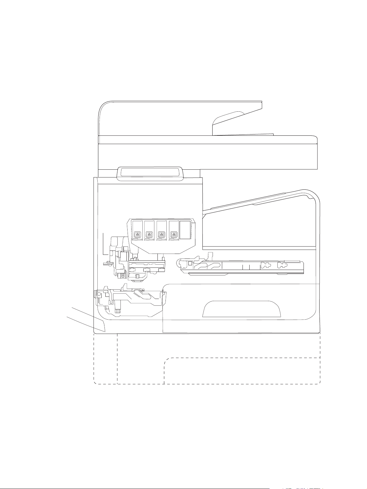
The product consists of the following components.
Figure 1-1 Main components
Optical
scan
carriage
Document feeder
Scanner
Control panel
Output bin
Printbar
Multipurpose tray
(Tray 1)
Duplex module\
Maintenance ink module
The product contains the following systems. See
Engine control system
●
Print subsystem
●
Service sled
Main input tray (Tray 2)
Optional tray (Tray 3)
● Paper-handling system
2 Chapter 1 Theory of operation ENWW

Servicing system
●
Aerosol management system
●
Scanner and document feeder system
●
Two elements influence the product architecture.
The first is the need to orient the printbar with its active face downwards and statically located
●
above the print media. This requires the printbar to move vertically to access its active face.
The second is producing face-down output. Rather than ejecting the page face-up immediately
●
after the ink is applied, as do many inkjet products, the printed page is routed up and back over
the printbar to eject face-down.
Operation sequence
The engine-control system on the formatter PCA controls the operational sequences. The following
table describes durations and operations for each period of a print operation from when the product is
turned on until the motor stops rotating.
Table 1-1 Operation sequence
Period Duration Purpose
Initial startup and
calibrations
Servicing operations Performed when the printbar
When the product is set up for
the first time from the factory.
is entering the capping state
after printing, when leaving
capping state after a print job
is initiated, or during extended
print jobs.
This period gets the product ready to print for the first time.
The product flushes the shipping and handling fluid out of
●
the printbar and replaces it with ink.
Die alignment — The product aligns the 10 die on the
●
printbar active face.
Die density leveling — The product measures and
●
compensates for the drop variation.
Servicing maintains the print quality by ensuring debris and
excess ink are removed and missing nozzles are replaced.
● Nozzle presence detection — The optical scan carriage
detects and disables inoperable nozzles, and replaces
them with operable nozzles.
● Printbar servicing—The Web wipe on the service sled
moves under the printbar to clean the active face and fire
the nozzles into the maintenance ink module to clear
clogs.
ENWW
Basic operation
3

Table 1-1 Operation sequence (continued)
Period Duration Purpose
Print preparation From the time the product
receives a product command
until paper enters the print
zone.
Printing From the end of the
preparation period until the
last sheet is delivered.
Prepares the product for a print job.
The printbar leaves the capping state as the service sled
●
moves away from the printbar.
If needed, some servicing occurs.
●
The printbar lowers to the printing position. The media
●
type and printing mode determine the print zone height.
● The product picks media from one of the input trays.
Every page from Tray 1 is scanned. For Tray 2 and
●
optional Tray 3, the product performs media edge
detection after printing the first sheet after the main or
optional tray is loaded. The last sheet of each job is also
scanned if at least five sheets have been printed.
The product monitors environmental conditions. The
●
product can slow the print speed if conditions are
significantly different than a normal office environment
(23° C (73.4° F), 50% relative humidity).
The formatter PCA processes print data and transmits the
●
data to the printbar.
Processes the print job.
● As the page travels through the print zone, the printbar
applies ink to the page.
Simplex print job–the page moves up, over the printbar,
●
and out to the output bin (face-down).
Duplex print job–the page moves up until the trailing edge
●
is 40 mm (1.5 inches) past the star-wheel jam reflective
sensor, then it reverses direction down through the duplex
path underneath the maintenance ink module, and then it
reenters the print zone where the printbar applies ink to
the second side.
The process continues until all the pages of the print job
●
are completed. The process can be interrupted by
occasional nozzle presence detection and servicing
events if the job includes many pages.
4 Chapter 1 Theory of operation ENWW

Table 1-1 Operation sequence (continued)
Period Duration Purpose
End of print job Performed after the print job is
completed, and continues until
the next job is initiated.
Standby The product is sitting idle,
waiting for the next print job to
be initiated.
This period puts the product in a state where it’s ready for the
next print job.
If needed, some servicing occurs.
●
The printbar moves to the capping position after a short
●
dwell interval.
The service sled moves to cap the printbar.
●
This period is intended to conserve energy when the product is
sitting idle. Certain functions might be disabled to save power,
then are re-started only when needed. The product has three
sleep modes:
Idle mode—The printbar is capped and the product is
●
ready to immediately start a new job
Sleep1 mode—After the product is inactive for about 10
●
minutes (a setting that can be adjusted from the control
panel), the control panel dims and the power LED blinks
to indicate the unit is in Sleep1. All product functions are
available.
Sleep2 mode—After the product is inactive for a longer
●
period of time (typically 2 hours, a setting that can be
adjusted from the control panel), the engine controller
powers down to minimize power consumption.
ENWW
Basic operation
5
System control
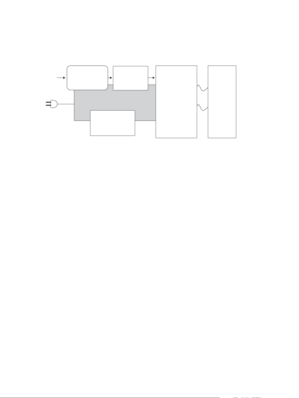
The system control coordinates all the other systems, according to commands from the formatter.
Figure 1-2 System control
I/O
Formatter
I/O, PDL, UI control
Power supply
Engine control
Motor + sensor drive
Datapath
ASIC +memory
Pen I/F
• Pen energy control
• Pen voltage
sequencing
• Signal integrity
• Ink-short protection
• Printhead
interconnects
• Ink supply
Printbar
40,000 nozzles
The system consists of five major sections.
Formatter
●
Data path
●
Engine control
●
Pen interface
●
Power supply
●
The engine PCA integrates both formatter and engine control electronics onto a single assembly. The
wireless radio unit (wireless models only) plugs into the back of the engine PCA, and the fax connects
via a short flat-flexible cable (FFC).
Formatter and data path
The formatter controller ASIC controls the input/output (I/O) control, the user interface, and the
rendering of page description language files into product-specific commands.
Input/output (I/O) control
The product supports 10/100 Ethernet, 802.11 wireless (wireless models), a rear USB host port, a
control panel USB host port, and analog fax port. For Ethernet networks, the formatter ASIC uses a
separate integrated circuit (Broadcom 5241) to provide the physical network layer.
The formatter ASIC controls the USB device and USB host as well.
Wireless I/O is provided via a separate radio module.
User interface
The product contains a 4.3-in color graphics display. For wireless models, there is an additional LED
to denote that the wireless feature is enabled. The control panel includes a USB host port for
connection to thumb drives.
6 Chapter 1 Theory of operation ENWW

Formatter digital ASIC
The formatter digital ASIC has dual ARM CPUs (792 MHz and 528 MHz) that execute firmware code
that provides high-level device control. The digital ASIC uses a standard PCle interface to pass data
to the engine control ASIC.
Formatter analog ASIC
The formatter analog ASIC generates the system voltage for the formatter, drives the scanner and
ADF motors, manages the real-time clock, and drives the fax speaker. Also, the engine uses this
ASIC to drive the ISS pumps, solenoids, and aerosol fan.
Real-time clock
The real-time clock (RTC) allows the fax module to time-stamp outgoing faxes. In addition, it
determines the elapsed time between printhead and ISS calibration events. The RTC uses a special
block inside the engine analog ASIC, along with a crystal and a battery.
Engine control
The engine controller digital ASIC receives high-level commands from the formatter, and it then
provides low-level control to the print mechanism. In particular, the engine controller digital ASIC and
its firmware control motors, system sensors, and the printbar. The engine controller analog ASIC
integrates motor drivers, voltage regulators, sensor interfaces, and supervisory circuits.
Engine controller digital ASIC
The engine controller digital ASIC has a high-performance 480 MHz ARM CPU and DSP coprocessors that execute firmware code to provide low-level engine control. It also drives the printbar
via 15 high-speed LVDS transmission lines, which are routed from the engine PCA to the printbar via
two large FFC cables. The engine controller digital ASIC receives pre-rendered data from the
formatter digital ASIC over a standard PCle interface.
In some product sleep modes, the digital ASIC powers down. If a print job is received while the
product is in this mode, power resumes to the digital ASIC, which then must “boot up”. This can take
approximately 15 seconds, which will delay the first page out (FPO) time accordingly. This sleep
mode typically begins after two hours of product inactivity, although the user can change this setting.
Engine controller analog ASIC
The engine uses two analog ASICs to generate the system voltages for the engine, drive the engine
motors, control various engine sensors, and monitor printbar power delivery for correct operation.
The engine has seven motors, some of which are shared with other subsystems:
Pick motor
●
Feed motor
●
ENWW
Duplex motor
●
Lift motor
●
System control
7

Eject motor
●
Sensor carriage motor
●
Aerosol fan motor
●
Each one is a DC motor with encoder feedback, to provide precision servo control. These motors are
driven directly by one of the engine analog ASICs. Small DC motors also are used to drive the ISS
pump and the aerosol fan. There are solenoids that actuate the ejection flap and the ISS priming
system.
The product uses many sensors to track the media as it travels through the paper path. Most of these
are optical REDI sensors, which are used in conjunction with mirrors to sense the presence or
absence of paper in a particular location. These are carefully aligned and calibrated at the factory, so
care must be taken when servicing these sensors. See the Remove and Replace chapter in the repair
manual for more details.
Other printed circuit-board assemblies (PCAs)
In addition to hosting the system ASICs, the engine PCA is home to many circuits needed to interface
to sensors and other sub-system components. In some cases, this circuitry is located on a smaller
remote PCA (SLB) to optimize cable interconnects.
Humidity sensor—The humidity sensor causes the product to adjust printing speed if ambient
●
conditions are outside the optimal humidity range. This sensor is calibrated at the factory to
ensure maximum accuracy.
Temperature sensor–The temperature sensor causes the product to adjust printing speed if
●
ambient conditions are outside the optimal temperature range. In some products, this sensor
resides on a separate, remote PCA.
Main tray presence sensor–The hall-effect sensor that detects if the main tray is properly
●
engaged resides on the back of the engine PCA. A small magnet on the back of the main tray
actuates the sensor. If the tray is fully engaged, the magnetic field strength is sufficient to trigger
the sensor.
Additionally, the product includes the following PCAs:
Front USB PCA–This PCA governs the control panel USB port.
●
Fax PCA–This PCA governs the product fax module.
●
Duplex module presence sensor–A hall-effect sensor that detects that the duplex module is
●
properly seated.
Power button PCA–This PCA includes the power button and power LED, as well as interface
●
cables to the duplex module presence sensor and the MP tray empty REDI sensor.
Accessory tray interconnect PCA–This PCA provides communication to optional Tray 3.
●
Pick encoder distribution PCA–This PCA includes the pick motor encoder and the pick motor
●
interconnect cable.
Eject encoder distribution PCA–This PCA includes the eject motor encoder, plus the
●
interconnect cables to the eject motor and the aerosol fan.
8 Chapter 1 Theory of operation ENWW

Print zone distribution PCA–This PCA joins interconnect cables to the following sensors:
●
separator REDI, feed motion encoder, main tray empty sensor, Top of Form (TOF) REDI sensor,
and the Print zone REDI sensor.
REDI distribution PCA—This PCA includes hall-effect sensors that detect ink cartridge door and
●
left door positions. It also combines the interconnect cables for the Eject REDI sensor, the Upper
paper path REDI sensor, the Lower paper path REDI sensor, and the eject flap opto flag sensor.
● Sensor carriage PCA — This PCA includes a carriage motion encoder, a ZIM sensor, and the
BDD sensor.
Printbar lift encoder distribution PCA — This PCA includes the printbar lift motion encoder, and
●
combines interconnect cables to the printbar lift motor, carriage motor, and eject flap solenoid.
Duplex encoder PCA — This PCA contains the motion encoder for the duplex motor.
●
SHAID PCA — This PCA contains interfaces to the out-of-ink sensors for the ink cartridges, and
●
combines the interface cables to the acumen PCA, the ISS pump, and the ISS solenoids.
Acumen PCA — This PCA contains interfaces to the acumen memory devices for the ink
●
cartridges.
Pen interface (I/F)
The printbar is the key component that differentiates this product from other inkjet products. The
conventional approach is to print a page in horizontal swaths by moving a “scanning” printhead
horizontally over a fixed sheet of paper, advancing the paper a fixed amount, and then printing the
next swath. With this product, the paper moves underneath a fixed page-wide printhead in a single
smooth motion.
Single pass page-wide printing requires that data and power be delivered to the printbar at a very
high rate, while also maintaining good control of paper position as it moves past the printhead
nozzles.
The engine PCA sends power and data to the printbar via two large flat flexible cables (36 and 38
pins). The printbar PCA routes power and data to 10 printhead die, which are attached to the PCA
using a flexible tab circuit and wire-bonding process.
There are also electronics to control the ink supply station (ISS). The SHAID PCA detects low-ink
conditions. It gauges ink levels by means of electrically sensing the presence of ink and/or ink foam in
the X-chamber. The SHAID PCA also collects and distributes electrical signals that drive the pushprime pump(s), engage the solenoids, and read the ink supply acumen data. All are routed through a
single 17-pin FFC from the SHAID PCA to the engine PCA.
Each ink supply has a memory tag that stores information about its type of ink, the amount of ink
remaining, and other critical data. It uses a special authentication scheme to ensure that only genuine
HP supplies are used and the product is not damaged by using invalid supplies. Acumen uses a twoline serial bus, which, along with 3.3 V and ground, is cabled via the SHAID PCA to the engine PCA
and the engine control digital ASIC.
ENWW
System control
9

Power supply
The power supply module converts 100-240 VAC to 33 VDC to power the system. The power supply
module has a sleep mode that reduces power consumption in system low-power modes. When in its
sleep mode, the power supply generates approximately 12 V.
The power supply module supplies 33 V to the engine PCA. The power supply module has two
operating modes, depending upon the state of its nSLEEP input pin:
Normal mode: Vo = 33 V ( nSLEEP = high logic level)
●
Sleep mode: Vo = 12 V ( nSLEEP = low logic level)
●
The power supply is a self-contained module that can be replaced if it is determined to be defective
(see the Remove and Replace chapter of the Repair Manual).
To ensure safe operation, the power supply will “latch off” if a persistent over-current fault condition
exists. This would typically be caused by a short-circuit from 33 V to ground in the product. In
addition, less severe faults can cause the power supply to latch off, if present for an extended period
of time, or if the product is operated above the recommended operating range.
NOTE: In some countries/regions, the product is equipped with a high-voltage power supply in order
to prevent power supply unit failures due to over-voltage conditions.
10 Chapter 1 Theory of operation ENWW
Print subsystem
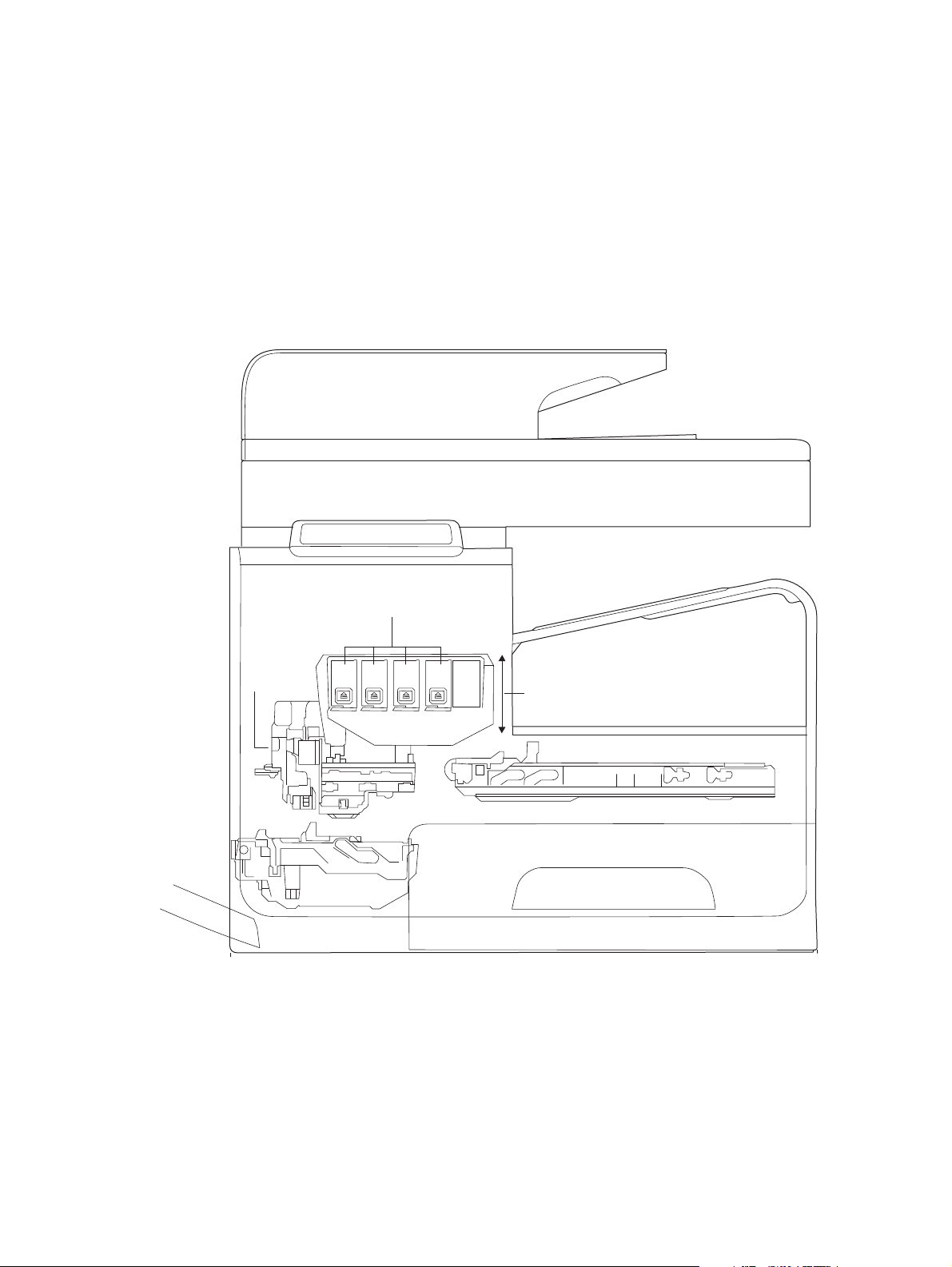
The print subsystem includes the following components.
Printbar
●
● Printbar lift
Ink cartridges
●
Optical scan carriage
●
Figure 1-3 Print subsystem components
Printbar
Ink cartridges
Optical
scan
carriage
Printbar
Printbar lift
The printbar’s fundamental purpose is to convert the digital firing instructions from the product
electronics into properly formed and timed microscopic drops of the four ink colors. The printbar
spans the full width of a letter/A4-size sheet (216 mm (8.5 in)), which allows the printbar to be
ENWW
Print subsystem
11

statically positioned within the product and have the media move underneath it, printing the entire
page in a single motion.
Figure 1-4 Printbar components
1
4
23
Table 1-2 Printbar components
Item Description
1 Ink cartridge connections
2 Thermal inkjet (TIJ) die array
3 Data/power flow and regulation
4 Inkflow channels and pressure regulation
The printbar has a fixed array of 10 thermal inkjet (TIJ) die oriented in two staggered rows. Each die
contains more than 1,000 nozzles for each of the four ink colors (black (K), cyan (C), magenta (M)
and yellow (Y)). Behind the die array are the ink flow channels and pressure regulation mechanisms
that supply the die array with ink at the proper pressure and flow. The die must also be fed power and
data at the appropriate levels and rates, which is the function of the onboard electronic circuitry.
Finally, situated at the top of the printbar, there are four ink cartridge receptacles, one for each color.
These cartridges are linked by flow connections to the rest of the printbar and supply the ink
necessary for its operation.
A sensor technology called back-scatter drop detect (BDD) monitors printbar health and calibrations.
This system looks at the reflection of the miniscule drops in flight, and then passes these signals
through high-speed, high-gain, bandpass filters. A complex artificial intelligence (AI) system decides
which drop ejectors are currently out of specifications, and which are not.
After the AI system determines which drop ejectors are out of specification, the product compensates
for them. Some ejectors use neighboring nozzles and at times even tiny amounts of other inks –
whichever combination of methods necessary to deliver the best print quality possible at that moment.
In some cases, fully half of the nozzles can be “out” without a noticeable degradation in quality. The
compensation is done in real time with a dedicated high-speed DSP. The system can scan portions of
the system after print jobs, but it is fully interruptible by new incoming print jobs.
12 Chapter 1 Theory of operation ENWW

Printbar air management system
The printbar uses a passive airgain management system. Air can enter the printbar from the following
sources:
Die outgassing (from air in the ink)
●
Air entering nozzles due to temperature / pressure variations
●
Air entry through the printbar structure
●
Air entry through the nozzles due to shipment vibration
●
Air that enters the printbar is warehoused. There is no mechanism to remove the air in the field. Of
the various mechanisms for air entry, the first three are generally benign, and rarely cause issues
during the expected life of the product. The fourth mechanism generally occurs during shipment. New
products are shipped with the printbar taped–which limits the amount of air gained. If the printbar isn’t
well restrained during shipment, then air gain can be significant. If the product is shipped after
removal of the printbar tape, airgain can be reduced either by ensuring that the poduct stays on its
base, or that the printbar is restrained. Both would be best.
Printbar lift
The printbar lift is responsible for positioning the printbar it within the product and moving it up and
down as required. This vertical motion is both to establish proper spacing to the paper during printing,
and to raise it to either access the active face or perform necessary calibrations.
During printing, the lift mechanism sets the printbar height and paper height depending on the type of
paper.
Ink cartridges
This product has new, state of the art pigmented inks. These inks are filtered using proprietary
processes to prevent printhead contamination. These inks are designed to produce optimal print
quality on ColorLok office papers, but also produce very good print quality on regular office papers
and specialty media.
Optical scan carriage
The optical scan carriage has optical sensors used for calibration. Its motion is along the long axis of
the printbar. These sensors are used by a number of in-product calibration features that are important
for proper subsystem function. The BDD sensor is located on the optical scan carriage.
Print system operational states
The print subsystem has a number of distinct operational states besides active printing.
Startup
ENWW
As it comes from the factory, the printbar is initially filled with an inert ink-substitute called Shipping
and Handling Fluid (SHF). This fluid, essential for the manufacture and transportation of the printbar,
Print subsystem
13

must be flushed and replaced with actual ink. This is accomplished during the startup phase. The
flushing process automatically commences when ink supplies are inserted and the unit powered up
for the first time. The SHF is removed by sustained printbar operation and replaced by ink from the
supplies. The process terminates once all the SHF has been flushed from the printbar.
Special host supplies are supplied with the product prior to its first use. These supplies contain
additional ink so that the SHF can be replaced with ink, and there will still be a 100 percent of ink
level. These supplies can be used only to initialize the product. You cannot use them in another
product that has been initialized.
NOTE: The initial startup time is noticeably longer than the following regular startup times.
Die alignment
Since there are 10 die comprising the printbar active face, each with associated positional tolerances,
an active calibration must be performed to prevent errors and allow a uniform ink application to the
media (without any gaps or overlaps between adjacent die). This die alignment is done by printing a
special diagnostic image on a sheet of paper and then scanning it with the optical scan carriage. Die
alignment is performed as part of initial unit startup, and can be performed manually as part of the
print quality recovery tool.
Die density leveling
There are also tolerances associated with the drops fired by the individual printbar die. Another active
calibration measures and compensates for these variations to produce a visually uniform ink
application to the media. Another set of diagnostic images is printed and scanned by the optical scan
carriage to achieve this die density leveling. Die alignment and die density leveling are usually paired
together.
Nozzle presence detection
In printing, since all the ink is applied in a single smooth motion of the media past the printbar, any
inoperable nozzle can show up as a noticeable streak. The operational state of each of the thousands
of nozzles comprising the printbar is periodically measured after a certain amount of printing. The
printbar is raised by the printbar lift, and the BDD assembly on the optical scan carriage watches for
drop presence as each nozzle is fired. Inoperable nozzles are turned off and other operable nozzles
employed on subsequent printed pages to apply the missing ink. Nozzle presence detection can be
interrupted by new incoming print jobs.
Media edge position detection
The product employs a learning algorithm to define media center as a function of input source–
multipurpose tray, main tray, or accessory tray. The edge scan is located downstream of the print
zone. As media is scanned, the media center database is updated. The image is registered to the
page using the media center database.
Servicing and capping
When not in use, the printbar is normally in the capped state – the printbar is fully raised, the service
sled is positioned underneath, and the printbar cap engaged against the printbar active face.
14 Chapter 1 Theory of operation ENWW

Printing
Servicing – the cleaning of the active face and the firing of the nozzles–can occur either during
Sleep2 mode or after extended time in storage. It can also occur during extended print jobs.
The printing state begins by the printbar leaving the capping state, and being lowered to the printing
position after the service sled moves out of the way. Concurrently, a sheet of media is picked from
one of the trays and the leading edge staged at the entrance to the print zone. Once the print data
has been processed and is available for transmission to the printbar, the sheet is fed at a constant
velocity through the print zone and the ink applied by the printbar.
In the case of one-sided printing the inked sheet is moved up, over and out to the output tray. For
two-sided printing the sheet is moved until its trailing edge is past the merge to the vertical path and
then it is reversed, through the duplex path underneath the maintenance ink module, and
reintroduced into the print zone for inking of the second side.
This process continues until all the pages of the print job are completed. If the print job is large
enough, it can be interrupted by servicing processes.
ENWW
Print subsystem
15
Paper-handling system
The paper-handling system moves paper through the product according to commands from the
formatter.
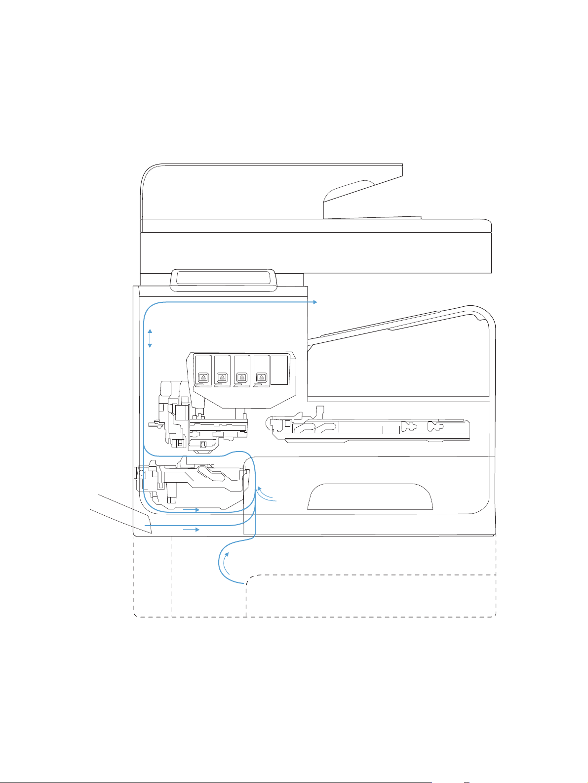
The following figure shows the product paper path.
Figure 1-5 Paper-handling system paper path
The paper path consists of the following major components:
Two integrated input trays plus one optional accessory tray
●
Four motors and a solenoid plus two more motors in the accessory tray
●
16 Chapter 1 Theory of operation ENWW

Duplex module
●
Sensors placed throughout the device, including the paper trays
●
Multiple feed rollers, pinch rollers, star wheels, and media guides
●
Transmission components (gears, shafts, levers, swingarms) that interface with other
●
subsystems such as the printbar and service sled.
Components of the paper path move the paper from the desired input tray to a position underneath
the printbar, and then deliver the printed result to the output tray. It is the combined orientations and
actions of the printbar, the printbar lift, and the paper path that establish the print zone, which is the
precisely controlled region in which the ink drops move from the active face of the printbar to the
paper situated 1 to 2 mm beneath it.
The following figure shows the product sensors.
ENWW
Paper-handling system
17
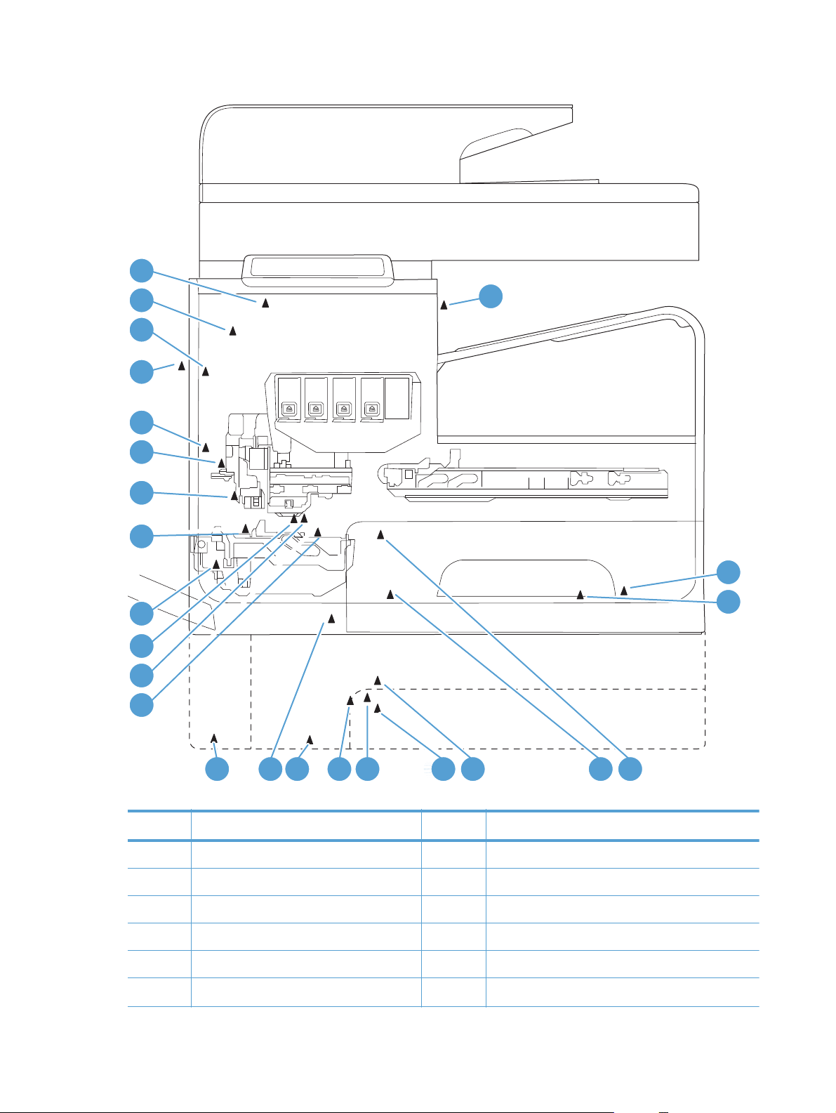
Figure 1-6 Product sensors
24
23
22
21
20
19
18
17
16
15
14
1
2
3
13
12 11 10 89 999997 6 45
Table 1-3 Product sensors
Item Description Item Description
1 Output flap jam sensor 13 Top of Form (TOF) REDI sensor (located on platen)
2 Ambient temperature sensor 14 Feed roller encoder
3 Ambient humidity sensor 15 Feed roller home sensor
4 Tray 2 pickup tire home sensor 16 Duplex module presence sensor
5 Tray 2 tray presence sensor 17 Print zone REDI sensor (located on platen)
6 Tray 3 pickup tire home sensor 18 Back-scatter drop detect sensor
18 Chapter 1 Theory of operation ENWW

Table 1-3 Product sensors (continued)
Item Description Item Description
7 Tray 3 paper presence sensor 19 Print calibration/Media edge detect sensor
8 Tray 3 separation sensor 20 Lower paper path REDI sensor
9 Tray 2 paper presence sensor 21 Left door open sensor
10 Tray 3 tray presence sensor 22 Upper paper path REDI sensor
11 Tray 1 paper presence sensor 23 Ink supply door open sensor
12 Tray 3 cleanout presence sensor 24 Eject REDI sensor
There are several motors in the product for pick, feed, duplexing, printbar lift, delivery, and the
scanning sensor carriage.
ENWW
Paper-handling system
19
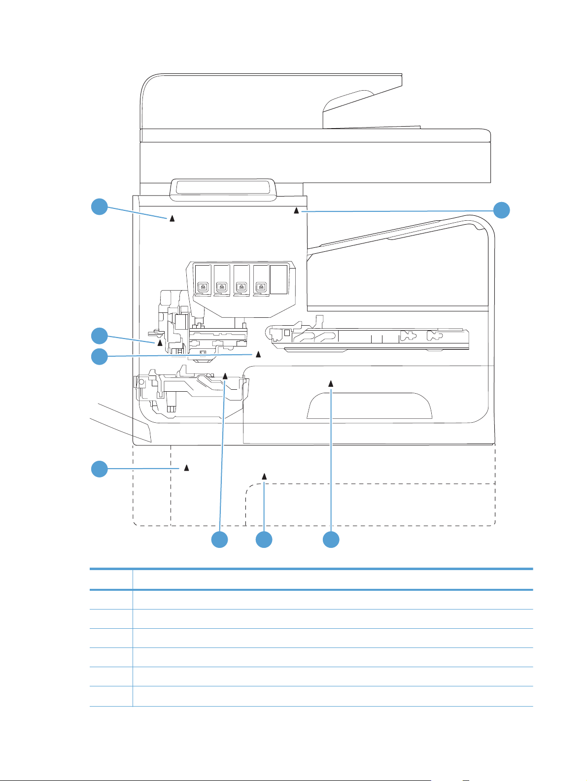
Figure 1-7 Paper-handling-system motors
8
7
6
5
1
234
Table 1-4 Paper-handling system motors
Item Description
1 Eject (or output drive) motor
2 Tray 2 pickup motor
3 Tray 3 pickup motor
4 Duplex Tray 1 motor
5 Tray 3 feed motor
6 Feed motor
20 Chapter 1 Theory of operation ENWW
Loading...