


 Loading...
HP EliteBook Folio 1030 G1 Notebook PC
Maintenance and Service Guide
© Copyright 2016 HP Development Company,
L.P.
AMD is a trademark of Advanced Micro Devices, Inc. Bluetooth is a trademark owned by its proprietor and used by HP Inc. under license. Intel, Celeron, and Pentium are trademarks of Intel Corporation in the U.S. and other countries. Microsoft and Windows are trademarks of the Microsoft group of companies.
The following applies to HP systems with Intel Skylake or next-generation silicon chip-based system shipping with Windows 7, Windows 8, Windows 8.1 or Windows 10 Pro systems downgraded to Windows 7 Professional, Windows 8 Pro, or Windows 8.1: This version of Windows running with the processor or chipsets used in this system has limited support from Microsoft. For more information about Microsoft’s support, please see Microsoft’s Support Lifecycle FAQ at https://support.microsoft.com/lifecycle
The information contained herein is subject to change without notice. The only warranties for HP products and services are set forth in the express warranty statements accompanying such products and services. Nothing herein should be construed as constituting an additional warranty. HP shall not be liable for technical or editorial errors or omissions contained herein.
First Edition: May 2016
Document Part Number: 839679-001
Product notice
This user guide describes features that are common to most models. Some features may not be available on your computer.
Not all features are available in all editions of Windows. This computer may require upgraded and/or separately purchased hardware, drivers and/or software to take full advantage of Windows functionality. Go to http://www.microsoft.com for details.
Software terms
By installing, copying, downloading, or otherwise using any software product preinstalled on this computer, you agree to be bound by the terms of the HP End User License Agreement (EULA). If you do not accept these license terms, your sole remedy is to return the entire unused product (hardware and software) within 14 days for a full refund subject to the refund policy of your seller.
For any further information or to request a full refund of the price of the computer, please contact your seller.
This computer may require upgraded and/ or separately purchased hardware and/or a DVD drive to install the Windows 7 software and take full advantage of Windows 7 functionality. See http://windows.microsoft.com/en-us/ windows7/get-know-windows-7 for details.

Safety warning notice
 WARNING! To reduce the possibility of heat-related injuries or of overheating the device, do not place the device directly on your lap or obstruct the device air vents. Use the device only on a hard, flat surface. Do not allow another hard surface, such as an adjoining optional printer, or a soft surface, such as pillows or rugs or clothing, to block airflow. Also, do not allow the AC adapter to contact the skin or a soft surface, such as pillows or rugs or clothing, during operation. The device and the AC adapter comply with the user-accessible surface temperature limits de ned by the International Standard for Safety of Information Technology Equipment (IEC 60950-1).
iii
iv Safety warning notice

Table of contents
1 Product description ....................................................................................................................................... |
1 |
2 External component dent c t on .................................................................................................................. |
4 |
Display .................................................................................................................................................................... |
4 |
Top .......................................................................................................................................................................... |
5 |
TouchPad ............................................................................................................................................. |
5 |
Lights ................................................................................................................................................... |
6 |
Buttons, speakers, and ngerprint reader .......................................................................................... |
7 |
Keys ..................................................................................................................................................... |
8 |
Left ......................................................................................................................................................................... |
9 |
Right ..................................................................................................................................................................... |
10 |
Bottom ................................................................................................................................................................. |
11 |
Service tag ........................................................................................................................................................... |
12 |
3 Illustrated parts catalog .............................................................................................................................. |
13 |
Computer major components .............................................................................................................................. |
13 |
Bracket Kit ............................................................................................................................................................ |
15 |
NFC Cable Kit ........................................................................................................................................................ |
16 |
Mass storage devices ........................................................................................................................................... |
17 |
Miscellaneous parts ............................................................................................................................................. |
17 |
4 Removal and replacement procedures preliminary requirements .................................................................... |
20 |
Tools required ...................................................................................................................................................... |
20 |
Service considerations ......................................................................................................................................... |
20 |
Plastic parts ....................................................................................................................................... |
20 |
Cables and connectors ...................................................................................................................... |
20 |
Grounding guidelines ........................................................................................................................................... |
20 |
Electrostatic discharge damage ........................................................................................................ |
20 |
Packaging and transporting guidelines .......................................................................... |
21 |
Workstation guidelines ................................................................................ |
22 |
5 Removal and replacement procedures for Authorized Service Provider parts ................................................... |
24 |
Component replacement procedures .................................................................................................................. |
24 |
Bottom cover ..................................................................................................................................... |
24 |
Keyboard ........................................................................................................................................... |
27 |
Solid-state drive ................................................................................................................................ |
31 |
v
WLAN module .................................................................................................................................... |
33 |
Display assembly ............................................................................................................................... |
35 |
RTC battery ........................................................................................................................................ |
39 |
Heat sink ............................................................................................................................................ |
41 |
Battery ............................................................................................................................................... |
43 |
Fingerprint reader board ................................................................................................................... |
45 |
NFC module ....................................................................................................................................... |
46 |
ForcePad (Touchpad) ......................................................................................................................... |
47 |
System board .................................................................................................................................... |
48 |
Speaker assembly ............................................................................................................................. |
51 |
6 Computer Setup (BIOS), TPM, and HP Sure Start in Windows 7 ......................................................................... |
52 |
Using Computer Setup ......................................................................................................................................... |
52 |
Starting Computer Setup .................................................................................................................. |
52 |
Navigating and selecting in Computer Setup ................................................................................... |
52 |
Restoring factory settings in Computer Setup ................................................................................. |
53 |
Updating the BIOS ............................................................................................................................. |
53 |
Determining the BIOS version ......................................................................................... |
53 |
Downloading a BIOS update ........................................................................................... |
54 |
Changing the boot order using the f9 prompt .................................................................................. |
55 |
TPM BIOS settings (select products only) ........................................................................................................... |
55 |
Using HP Sure Start (select products only) ......................................................................................................... |
55 |
7 Computer Setup (BIOS), TPM, and HP Sure Start in Windows 10 ........................................................................ |
56 |
Using Computer Setup ......................................................................................................................................... |
56 |
Starting Computer Setup .................................................................................................................. |
56 |
Navigating and selecting in Computer Setup ................................................................................... |
56 |
Restoring factory settings in Computer Setup ................................................................................. |
57 |
Updating the BIOS ............................................................................................................................. |
57 |
Determining the BIOS version ......................................................................................... |
57 |
Downloading a BIOS update ........................................................................................... |
58 |
Changing the boot order using the f9 prompt .................................................................................. |
59 |
TPM BIOS settings (select products only) ........................................................................................................... |
59 |
Using HP Sure Start (select products only) ......................................................................................................... |
59 |
8 Using HP PC Hardware Diagnostics (UEFI) ....................................................................................................... |
60 |
Downloading HP PC Hardware Diagnostics (UEFI) to a USB device .................................................................... |
60 |
9 Backup and recovery in Windows 7 ................................................................................................................ |
62 |
Creating recovery media and backups ................................................................................................................ |
62 |
vi
Guidelines .......................................................................................................................................... |
62 |
Creating recovery media with HP Recovery Disc Creator ................................................................. |
62 |
Creating recovery media ................................................................................................. |
63 |
Backing up your information ............................................................................................................. |
63 |
Performing a system recovery ............................................................................................................................ |
64 |
Using the Windows recovery tools .................................................................................................... |
64 |
Using f11 recovery tools (select products only) ............................................................................... |
65 |
Using Windows 7 operating system media ....................................................................................... |
65 |
10 Backup and recovery in Windows 10 ............................................................................................................ |
67 |
Creating recovery media and backups ................................................................................................................ |
67 |
Creating HP Recovery media (select products only) ......................................................................... |
67 |
Using Windows tools ........................................................................................................................................... |
68 |
Restore and recovery ........................................................................................................................................... |
69 |
Recovering using HP Recovery Manager ........................................................................................... |
69 |
What you need to know before you get started ............................................................. |
69 |
Using the HP Recovery partition (select products only) ................................................. |
70 |
Using HP Recovery media to recover .............................................................................. |
70 |
Changing the computer boot order ................................................................................ |
71 |
Removing the HP Recovery partition (select products only) ......................................... |
71 |
11 pec c t ons ............................................................................................................................................ |
72 |
Computer speci cations ...................................................................................................................................... |
72 |
33.78-cm (13.3-in) display speci cations .......................................................................................................... |
73 |
M.2 solid-state drive speci cations .................................................................................................................... |
74 |
12 Statement of memory volatility .................................................................................................................. |
75 |
Nonvolatile memory usage ................................................................................................................................. |
79 |
Questions and answers ....................................................................................................................................... |
81 |
Using HP Sure Start (select models only) ............................................................................................................ |
82 |
13 Power cord set requirements ...................................................................................................................... |
83 |
Requirements for all countries ............................................................................................................................ |
83 |
Requirements for speci c countries and regions ................................................................................................ |
83 |
14 Recycling .................................................................................................................................................. |
85 |
Index ............................................................................................................................................................. |
86 |
vii
viii

1Product description
Category |
Description |
|
|
Product Name |
HP EliteBook Folio 1030 G1 Notebook PC |
|
|
Processors |
6th generation Intel® Core® M processors: |
|
● 6Y75, 1.2-GHz (max turbo frequency 3.1-GHz), 4-MB L3 Cache, 4.5W |
|
● 6Y57, 1.1-GHz (max turbo frequency 2.8-GHz), 4-MB L3 Cache, 4.5W |
|
● 6Y54, 1.1-GHz (max turbo frequency 2.7-GHz), 4-MB L3 Cache, 4.5W |
|
|
Chipset |
Mobile Intel CM236 chipset |
|
Integrated with processor |
|
|
Graphics |
Intel UMA Graphics (GT2) with shared video memory |
|
Intel HD Graphics 515 |
|
|
Panels |
33.78-cm (13.3-in), eDP 1.3 |
|
Full high-de nition (FHD), 1920×1080, non-touch display, 300 nits |
|
Quad high-de nition (QHD+), 3200×1800, touch display, 300 nits |
|
|
Memory |
On-board (soldered) memory |
|
LPDDR3, 1866 MHz, dual channel support |
|
Supports 8 GB or 16 GB of total system memory |
|
|
Primary storage |
Supports the following M.2 SSDs: |
|
● 512-GB SATA-3, TLC |
|
● 256-GB SATA-3, TLC |
|
● 256-GB, SATA-3, SS SED, MLC, OPAL 2 |
|
● 256-GB, PCIe-3x4 NVMe SS MLC |
|
● 240-GB, SATA-3 MLC |
|
● 180-GB, SATA-3 SS SED, MLC |
|
● 180-GB, SATA-3, SS MLC |
|
● 128-GB, SATA-3, SS TLC |
|
|
Audio and video |
Two stereo speakers |
|
Intel Smart Sound Technology |
|
HD audio with DTS Studio Sound |
|
Integrated 720p webcam |
|
Integrated dual-array microphone |
|
|
Ethernet |
No direct Ethernet support. Ethernet available from accessory dongle. |
|
|
Wireless |
WPAN Bluetooth |
|
Bluetooth 4.2 supported with combo card |
1

Category |
Description |
|
|
|
|
|
WLAN options via M.2 |
|
|
Two WLAN antennas built into display assembly |
|
|
Bluetooth Disabled IOPT |
|
|
Support for the following WLAN formats: |
|
|
● |
Intel Dual Band Wireless-AC 8260; 802.11ac, 2x2 + Bluetooth 4.2 |
|
Supports no WLAN option |
|
|
|
|
|
NFC |
|
|
Integrated NFC module |
|
|
Supports "No NFC" option |
|
|
NFC antenna con gured with NFC option |
|
|
|
|
Ports |
Headphone/microphone combo |
|
|
HDMI |
|
|
Docking connector |
|
|
Multi-Pin AC port, 4.5 mm |
|
|
(1) USB-C 3.0 charging port (15W) |
|
|
(2) USB 3.0 charging ports |
|
|
|
|
Docking |
HP Docking Station |
|
|
|
|
Keyboard/pointing devices |
Keyboard |
|
|
DuraKeys, backlit |
|
|
Spill-resistant with drain |
|
|
|
|
|
TouchPad |
|
|
Gestures enabled by default: twonger scrolling, twonger pinch-zoom |
|
|
Taps enabled by default |
|
|
Supports 2-way scroll |
|
|
Glass with chemical etched surface |
|
|
|
|
Power requirements |
AC adapters |
|
|
45-W HP Smart AC adapter |
|
|
45-W, 2-prong AC adapter |
|
|
65-W HP Smart AC adapter |
|
|
65-W Slim AC adapter |
|
|
Power cords |
|
|
2-wire plug (4.5 mm) (1.0 m)(only available with 45-W 2-prong adapter |
|
|
3-wire plug with ground pin (4.5 mm) (1.0 m) |
|
|
3-wire plug with ground pin (4.5 mm) (1.8 m) |
|
Battery
4-cell, 40-Whr, 2.4 Ahr long life polymer battery
2Chapter 1 Product description
Category |
Description |
|
|
|
|
Security |
Security lock |
|
|
Fingerprint reader |
|
|
Trusted Platform Module (TPM) 1.2/2.0 ( n neon, soldered down) |
|
|
Drive encryption preboot (password, ngerprint, and select smart cards) |
|
|
Preboot authentication (password and ngerprint) |
|
|
|
|
Operating system |
Preinstalled |
|
|
● |
Windows 7 Professional 64 |
|
● |
Windows 10 Pro 64 |
|
● |
Windows 10 Home 64 Chinese Market CPPP |
|
● |
Windows 10 Home 64 High-end |
|
● |
Windows 10 Home 64 High-end Single Language |
|
● |
Windows 10 Professional 64 Downgrade Windows 7 64 |
|
● |
Windows 10 Pro 64 StF MSNA High-end |
|
● |
Windows 10 Pro 64 Downgrade Win 7 64 StF MSNA High-end |
|
● |
Windows 10 Pro 64 StF MSNA Strategic |
|
● |
Windows 10 Pro 64 Downgrade Windows 7 64 StF MSNA Strategic |
|
● |
Windows 7 Pro 64 StF MSNA Strategic |
|
● |
FreeDOS 2.0 |
|
|
|
|
Restore media–DR-DVD |
|
|
● |
Windows 7 (32 & 64 bit) |
|
● |
Windows 10 |
|
|
|
|
Restore media–OS-DVD |
|
|
● |
Windows 10 Pro 64 |
|
● |
Windows 7 Pro 64 |
ert ed
|
● |
Microsoft WHQL: Windows 7 64 and Windows 10 64 |
|
|
|
|
Web-only support |
|
|
● |
Windows 10 Enterprise |
|
● |
Windows 8.1 Enterprise 64 |
|
● |
Windows 7 Professional 32 |
|
● |
Windows 7 Enterprise 64 |
|
● |
Windows 7 Enterprise 32 |
|
|
|
Serviceability |
End user replaceable parts: |
|
|
● |
AC adapter |
|
|
|
3

2 External component dent c t on
Display
Component |
Description |
|
|
|
|
(1) |
Internal microphones (2) |
Record sound. |
|
|
|
(2) |
Webcam light |
On: The webcam is in use. |
|
|
|
(3) |
Webcam |
Records video and captures photographs. Some models allow you to |
|
|
video conference and chat online using streaming video. |
|
|
To use the webcam in Windows 10: |
|
|
▲ Type camera in the taskbar search box, and then select |
|
|
Camera. |
|
|
To use the webcam in Windows 7, select Start > All Programs > |
|
|
Communication and Chat > HP WebCam. |
|
|
|
(4) |
WLAN antennas* (2) (select products only) |
Send and receive wireless signals to communicate with wireless local |
|
|
area networks (WLANs). |
|
|
|
(5) |
Near Field Communication (NFC) antenna* (select |
Sends and receives wireless signals to communicate and transfer |
|
products only) |
data/info to and from your NFC-compatible devices. |
*The antennas are not visible from the outside of the computer. For optimal transmission, keep the areas immediately around the antennas free from obstructions.
4 Chapter 2 External component identi cation

Component |
Description |
For wireless regulatory notices, see the section of the Regulatory, Safety, and Environmental Notices that applies to your country or region.
To access this guide in Windows 10:
1.Type support in the taskbar search box, and then select the HP Support Assistant app.
‒ or –
Click the question mark icon in the taskbar.
2. Select My PC, select the pec c t ons tab, and then select User Guides.
To access the user guides in Windows 7, select Start > All Programs > HP Help and Support > HP Documentation.
Top
TouchPad
Component |
|
Description |
|
|
|
|
|
(1) |
TouchPad on/o button |
Turns the TouchPad on and o . |
|
|
|
|
|
(2) |
TouchPad zone |
Reads your nger gestures to move the pointer or activate |
|
|
|
items on the screen. |
|
|
|
NOTE: The TouchPad detects the force of the |
nger pressure |
|
|
being applied while using gestures. Press your |
ngers down on |
|
|
the TouchPad with force while gesturing to accelerate the |
|
|
|
gesture motion. |
|
|
|
|
|
(3) |
Left TouchPad button |
Functions like the left button on an external mouse. |
|
|
|
|
|
(4) |
Right TouchPad button |
Functions like the right button on an external mouse. |
|
|
|
|
|
Top 5

Lights
Component |
|
Description |
|
|
|
|
|
(1) |
Power light |
● |
On: The computer is on. |
|
|
● |
Blinking: The computer is in the Sleep state, a power-saving |
|
|
|
state. The computer shuts o power to the display and |
|
|
|
other unneeded components. |
|
|
● |
The computer is o or in Hibernation. Hibernation is a |
|
|
|
power-saving state that uses the least amount of power. |
|
|
|
|
(2) |
Caps lock light |
On: Caps lock is on, which switches the key input to all capital |
|
|
|
letters. |
|
|
|
|
|
(3) |
Mute light |
● |
Amber: Computer sound is o . |
|
|
● |
Computer sound is on. |
|
|
|
|
(4) |
Microphone mute light |
● |
Amber: microphone sound is o . |
|
|
● |
microphone sound is on. |
|
|
|
|
(5) |
Wireless light |
● |
White: An integrated wireless device, such as a wireless |
|
|
|
local area network (WLAN) device and/or a Bluetooth® |
|
|
|
device, is on. |
|
|
● |
Amber: All wireless devices are o . |
|
|
|
|
(6) |
Num lock light |
On: Num lock is on. |
|
|
|
|
|
(7) |
TouchPad light |
● |
Amber: The TouchPad is o . |
|
|
● |
The TouchPad is on. |
|
|
|
|
6 Chapter 2 External component identi cation
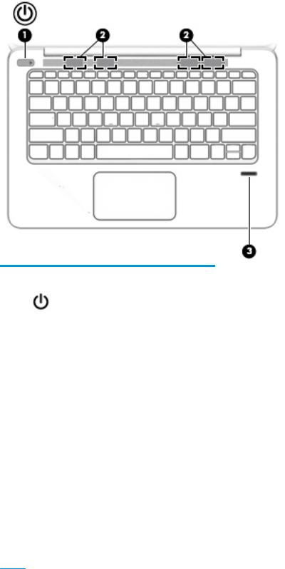
Buttons, speakers, and n erpr nt reader
Component |
|
Description |
|
|
|
|
|
(1) |
Power button |
● |
When the computer is o , press the button to turn on the |
|
|
|
computer. |
|
|
● |
When the computer is on, press the button briefly to initiate |
|
|
|
Sleep. |
|
|
● |
When the computer is in the Sleep state, press the button |
|
|
|
briefly to exit Sleep. |
|
|
● |
When the computer is in Hibernation, press the button |
|
|
|
briefly to exit Hibernation. |
|
|
CAUTION: Pressing and holding down the power button results |
|
|
|
in the loss of unsaved information. |
|
|
|
If the computer has stopped responding and Windows® shutdown |
|
|
|
procedures are ine ective, press and hold the power button for at |
|
|
|
least 5 seconds to turn o the computer. |
|
|
|
To learn more about your power settings in Windows 10, see your |
|
|
|
power options. |
|
|
|
▲ |
Type power in the taskbar search box, and then select |
Power and sleep settings.
‒ or –
Right-click the Start button, and then select Power
Options.
To learn more about your power settings in Windows 7, select
Start > Control Panel > System and Security > Power Options.
Top 7
Component |
|
Description |
|
|
|
(2) |
Speakers (4) |
Produce sound. |
|
|
|
(3) |
Fingerprint reader |
Allows a ngerprint logon to Windows, instead of a password |
|
|
logon. |
|
|
|
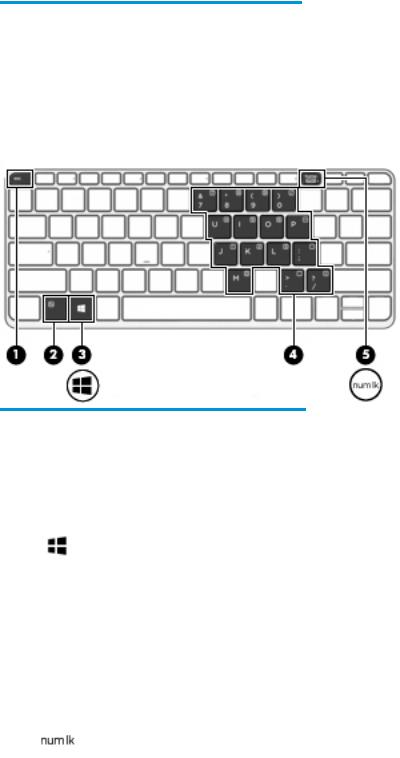
Keys
Component |
|
Description |
|
|
|
(1) |
esc key |
Displays system information when pressed in combination with |
|
|
the fn key. |
|
|
|
(2) |
fn key |
Executes frequently used system functions when pressed in |
|
|
combination with a function key, the num lock key, or the esc |
|
|
key. |
|
|
|
(3) |
Windows key |
Windows 10: |
|
|
Opens the Start menu. |
|
|
NOTE: Pressing the Windows key again will close the Start |
|
|
menu. |
|
|
Windows 7: |
|
|
Displays the Windows Start menu. |
|
|
|
(4) |
Embedded numeric keypad |
A numeric keypad superimposed over the keyboard alphabet |
|
|
keys that enables you to add, subtract, and perform other |
|
|
numeric tasks. When num lock is on, the keypad can be used like |
|
|
an external numeric keypad. |
|
|
|
(5) |
num lock key |
Turns the embedded numeric keypad on and o . |
|
|
|
8 Chapter 2 External component identi cation

Left
Component |
|
Description |
|
|
|
(1) |
Security cable slot |
Attaches an optional security cable to the computer. |
|
|
NOTE: The security cable is designed to act as a deterrent, but |
|
|
it may not prevent the computer from being mishandled or |
|
|
stolen. |
|
|
|
(2) |
HDMI port |
Connects an optional video or audio device, such as a high- |
|
|
de nition television, any compatible digital or audio component, |
|
|
or a high-speed High De nition Multimedia Interface (HDMI) |
|
|
device. |
|
|
|
(3) |
USB 3.0 charging (powered) port |
Connects an optional USB device, such as a keyboard, mouse, |
|
|
external drive, printer, scanner or USB hub. Standard USB ports |
|
|
will not charge all USB devices or will charge using a low current. |
|
|
Some USB devices require power and require you to use a |
|
|
powered port. |
|
|
NOTE: USB charging ports can also charge select models of |
|
|
cell phones and MP3 players, even when the computer is o . |
|
|
NOTE: The battery can be depleted quickly if you charge |
|
|
multiple devices while operating on battery power. |
|
|
|
(4) |
USB Type-C (charging) port |
Connects any USB device with a Type-C connector. |
|
|
NOTE: USB Type-C ports charge products such as cell phones, |
|
|
laptops, tablets, and MP3 players, even when the computer is |
|
|
o . Also, some USB Type-C ports connect DisplayPort, VGA, |
|
|
HDMI, Thunderbolt and other video devices to provide video |
|
|
output. |
NOTE: Adapters (purchased separately) may be required.
Left 9

Right
Component |
|
Description |
|
|
|
|
|
(1) |
Audio-out (headphone)/Audio-in (microphone) |
Connects optional powered stereo speakers, headphones, |
|
|
combo jack |
earbuds, a headset, or a television audio cable. Also connects an |
|
|
|
optional headset microphone. This jack does not support |
|
|
|
optional microphone-only devices. |
|
|
|
WARNING! To reduce the risk of personal injury, adjust the |
|
|
|
volume before putting on headphones, earbuds, or a headset. |
|
|
|
For additional safety information, refer to the Regulatory, |
|
|
|
Safety, and Environmental Notices. |
|
|
|
To access this guide in Windows 10: |
|
|
|
1. |
Type support in the taskbar search box, and then select |
|
|
|
the HP Support Assistant app. |
|
|
|
‒ or – |
|
|
|
Click the question mark icon in the taskbar. |
|
|
2. |
Select My PC, select the pec c t ons tab, and then |
|
|
|
select User Guides. |
|
|
To access the user guides, select Start > All Programs > HP Help |
|
|
|
and Support > HP Documentation. |
|
|
|
NOTE: When a device is connected to the jack, the computer |
|
|
|
speakers are disabled. |
|
|
|
|
|
(2) |
USB 3.0 charging (powered) port |
Connects an optional USB device, such as a keyboard, mouse, |
|
|
|
external drive, printer, scanner or USB hub. Standard USB ports |
|
|
|
will not charge all USB devices or will charge using a low |
|
|
|
current. Some USB devices require power and require you to use |
|
|
|
a powered port. |
|
|
|
NOTE: USB charging ports can also charge select models of |
|
|
|
cell phones and MP3 players, even when the computer is o . |
|
|
|
NOTE: The battery can be depleted quickly if you charge |
|
|
|
multiple devices while operating on battery power. |
|
|
|
|
|
(3) |
Docking connector |
Connects an optional docking device. |
|
|
|
|
|
(4) |
Battery light |
When AC power is connected: |
|
|
|
● |
White: The battery charge is greater than 90 percent. |
|
|
● |
Amber: The battery charge is from 0 to 90 percent. |
|
|
● |
The battery is not charging. |
When AC power is disconnected (battery not charging):
10 Chapter 2 External component identi cation
Component |
|
Description |
|
|
|
|
|
|
|
● |
Blinking amber: The battery has reached a low battery |
|
|
|
level. When the battery has reached a critical battery level, |
|
|
|
the battery light begins blinking rapidly. |
|
|
● |
The battery is not charging. |
|
|
|
|
(5) |
Power connector |
Connects an AC adapter. |
|
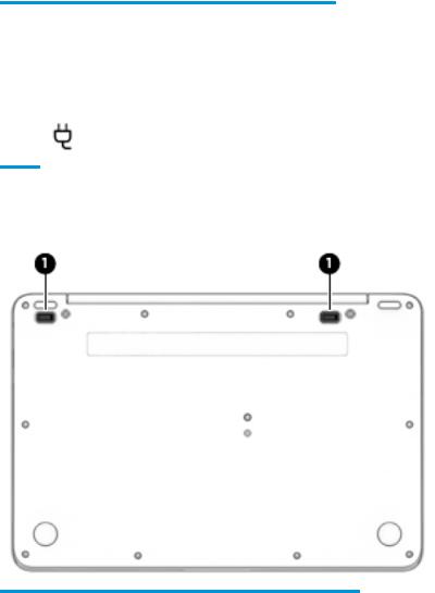
Bottom
Component |
|
Description |
|
|
|
(1) |
Docking device receptors (2) |
Connects an optional docking device. |
|
|
|
Bottom 11

Service tag
When ordering parts or requesting information, provide the computer serial number and model number provided on the service tag.
Item |
Description |
Function |
|
|
|
(1) |
Product name |
This is the product name affixed to the front of |
|
|
the computer. |
|
|
|
(2) |
Serial number (s/n) |
This is an alphanumeric identi er that is unique to |
|
|
each product. |
|
|
|
(3) |
Part number/Product number (p/n) |
This number provides speci c information about |
|
|
the product's hardware components. The part number helps |
|
|
a service technician to determine what components |
|
|
and parts are needed. |
|
|
|
(4) |
Warranty period |
This number describes the duration of the warranty period |
|
|
for the computer. |
|
|
|
12 Chapter 2 External component identi cation

3Illustrated parts catalog
Computer major components
Computer major components 13

Item |
Component |
Spare part number |
|
|
|
(1) |
Display assembly, touch screen, QHD+ |
842280-001 |
|
NOTE: Touch displays are only spared as full hinge-ups. Individual components are not |
|
|
spared for touch screen displays. |
|
|
|
|
(2) |
Display assembly, non-touch screen, FHD |
850931-001 |
|
NOTE: Non-touch displays are only spared as full hinge-ups. Individual components are |
|
|
not spared for non-touch screen displays. |
|
|
|
|
(3) |
Keyboard (backlit; includes keyboard cable and backlight cable): |
842324-xx1 |
|
NOTE: For a detailed list of keyboard country codes, see Keyboard on page 27. |
|
|
|
|
(4) |
Top cover (includes power button) |
842284-001 |
|
|
|
(5) |
ForcePad (Touchpad) |
842287-001 |
|
The ForcePad cable is available in the Cable Kit using spare part number 842293-001. |
|
|
|
|
(6) |
Fingerprint reader board (includes bracket and cable) |
790074-001 |
|
|
|
(7) |
NFC module |
790069-001 |
|
|
|
|
NFC Cable Kit, includes: |
842323-001 |
|
|
|
|
NFC module antenna |
|
|
|
|
|
NFC module cable |
|
|
|
|
(8) |
Speakers (includes cable) |
837352-001 |
(9)System board (includes processor and replacement thermal material): All system boards use the following part numbers:
xxxxxx-001: Windows 7 or non-Windows operating systems xxxxxx-601: Windows 10 operating system
|
Equipped with 16 GB of system memory and an Intel Core M7-6Y75 processor |
842326-xxx |
|
|
|
|
Equipped with 16 GB of system memory and an Intel Core M5-6Y57 processor |
842328-xxx |
|
|
|
|
Equipped with 8 GB of system memory and an Intel Core M5-6Y57 processor |
842327-xxx |
|
|
|
|
Equipped with 8 GB of system memory and an Intel Core M5-6Y54 processor |
842325-xxx |
|
|
|
(10) |
Solid-state drive, M.2 |
|
|
|
|
|
512-GB, MLC |
842300-001 |
|
|
|
|
256-GB, SED, OPAL2 |
842298-001 |
|
|
|
|
256-GB, TLC |
842610-001 |
|
|
|
|
256-GB, PCIe, NVMe, MLC |
842299-001 |
|
|
|
|
240-GB, MLC |
842611-001 |
|
|
|
|
180-GB, MLC |
842296-001 |
|
|
|
|
180-GB, SED, OPAL2 |
842297-001 |
|
|
|
|
128-GB, TLC |
842295-001 |
|
|
|
(11) |
WLAN module |
|
|
|
|
14 Chapter 3 Illustrated parts catalog

Item |
Component |
Spare part number |
|
|
|
|
Intel Dual Band Wireless-AC 8260; 802.11ac, 2x2 + Bluetooth 4.2 |
806721-005 |
|
|
|
(12) |
RTC battery (includes double-sided tape) |
702853-001 |
|
|
|
(13) |
Heat sink/thermal module (includes replacement thermal material): |
842301-001 |
|
|
|
(14) |
Battery (4-cell, 40-Wh, 2.6-Ah, li ion) |
826038-005 |
|
|
|
(15) |
Bottom cover |
842283-001 |
|
|
|
Bracket Kit
Item |
Component |
Spare part number |
|
|
|
|
Bracket Kit |
842302-001 |
|
|
|
(1) |
Fingerprint reader bracket |
|
|
|
|
(2) |
Left display (QHD) bracket |
|
|
|
|
(3) |
Right display (QHD) bracket/clip |
|
|
|
|
|
Top cable clip (left and right; not illustrated) |
|
|
|
|
Bracket Kit 15

NFC Cable Kit
Item |
Component |
Spare part number |
|
|
|
|
NFC Cable Kit |
842323-001 |
|
|
|
(1) |
NFC cable |
|
|
|
|
(2) |
NFC antenna |
|
|
|
|
16 Chapter 3 Illustrated parts catalog

Mass storage devices
Description |
Spare part number |
|
|
Solid-State Drive M.2 |
|
|
|
512-GB, MLC |
842300-001 |
|
|
256-GB, SED, OPAL2 |
842298-001 |
|
|
256-GB, TLC |
842610-001 |
|
|
256-GB, PCIe, NVMe, MLC |
842299-001 |
|
|
240-GB, MLC |
842611-001 |
|
|
180-GB, MLC |
842296-001 |
|
|
180-GB, SED, SED, OPAL2 |
842297-001 |
|
|
128-GB, TLC |
842295-001 |
|
|
External optical drive (DVD±RW Double Layer Drive) |
747080-001 |
|
|
Miscellaneous parts
Component |
Spare part number |
|
|
AC adapter: |
|
|
|
45-W HP Smart AC adapter (non-PFC) – non-slim |
741727-001 |
|
|
45-W AC adapter (non-PFC), 2-prong |
742436-001 |
|
|
65-W HP Smart AC adapter, 4.5 mm, EM |
714657-001 |
|
|
65-W HP Smart AC travel adapter |
693716-001 |
Use spare part number 736697-001,“Cable, detachable, with tips (4.5 mm and 7.4 mm tips)” with this |
|
adapter. |
|
|
|
Smart AC adapter dongle, 7.4mm |
734734-001 |
|
|
Power cord (3-pin, C5, black, 1.83-m), for use in: |
|
|
|
Argentina |
401300-001 |
|
|
Australia |
213356-001 |
|
|
Brazil |
438722-001 |
|
|
Denmark |
213353-001 |
|
|
Europe (Austria, Belgium, Finland, France, Germany, the Netherlands, Norway and Sweden) |
213350-001 |
|
|
India |
404827-001 |
|
|
Israel |
398063-001 |
|
|
Italy |
213352-001 |
|
|
Japan |
349756-001 |
|
|
North America |
213349-001 |
|
|
Mass storage devices 17

Component |
Spare part number |
|
|
People’s Republic of China |
286497-001 |
|
|
South Africa |
361240-001 |
|
|
South Korea |
267836-001 |
|
|
Switzerland |
213354-001 |
|
|
Taiwan |
393313-001 |
|
|
United Kingdom and Singapore |
213351-001 |
|
|
Power cord (3-pin, C5, black, 1.00-m), for use in: |
|
|
|
Argentina |
401300-007 |
|
|
Australia |
213356-008 |
|
|
Brazil |
438722-004 |
|
|
Denmark |
213353-008 |
|
|
Europe (Austria, Belgium, Finland, France, Germany, the Netherlands, Norway and Sweden) |
213350-009 |
|
|
India |
404827-003 |
|
|
Israel |
398063-003 |
|
|
Italy |
213352-008 |
|
|
Japan |
349756-002 |
|
|
North America |
213349-009 |
|
|
People’s Republic of China |
286497-008 |
|
|
South Africa |
361240-002 |
|
|
South Korea |
267836-008 |
|
|
Switzerland |
213354-008 |
|
|
Taiwan |
393313-003 |
|
|
Thailand |
285096-006 |
|
|
United Kingdom and Singapore |
213351-008 |
|
|
Power cord (C7, black, 1.00-m), for use in: |
|
|
|
Japan |
190548-003 |
|
|
Screw Kit |
842285-001 |
|
|
Plastics Kit (includes system board clip) |
860705-001 |
|
|
Cable, detachable, with tips (4.5 mm and 7.4 mm tips) |
736697-001 |
For use with 65-W HP Smart AC travel adapter, spare part number 693716-001. |
|
|
|
Docking station cable lock |
575921-001 |
|
|
Lock, HP Ultraslim Keyed Cable Lock |
703372-001 |
|
|
Mouse: |
|
|
|
HP USB optical travel mouse |
757770-001 |
|
|
18 Chapter 3 Illustrated parts catalog

Component |
Spare part number |
|
|
HP Comfort Grip wireless mouse |
691922-001 |
|
|
HP USB laser mouse |
674318-001 |
|
|
Top load case |
679921-001 |
|
|
HP professional slim top load case |
703888-001 |
|
|
HP business backpack |
718548-001 |
|
|
Adapters |
|
|
|
HDMI to DVI-D adapter |
691227-001 |
|
|
Docking connector to ethernet (RJ-45)/VGA |
797848-001 |
|
|
HDMI to VGA |
701943-001 |
|
|
HP USB-C to USB 3.0 adapter |
814618-001 |
|
|
Miscellaneous parts 19

4Removal and replacement procedures preliminary requirements
Tools required
You will need the following tools to complete the removal and replacement procedures:
●Flat-bladed screw driver
●Torx T8 screw driver
●Phillips P0 and P1 screw drivers
●Non-marking pry tool
Service considerations
The following sections include some of the considerations that you must keep in mind during disassembly and assembly procedures.
 NOTE: As you remove each subassembly from the computer, place the subassembly (and all accompanying screws) away from the work area to prevent damage.
Plastic parts
 CAUTION: Using excessive force during disassembly and reassembly can damage plastic parts. Use care when handling the plastic parts. Apply pressure only at the points designated in the
maintenance instructions.
Cables and connectors
 CAUTION: When servicing the computer, be sure that cables are placed in their proper locations during the reassembly process. Improper cable placement can damage the computer.
Cables must be handled with extreme care to avoid damage. Apply only the tension required to unseat or seat the cables during removal and insertion. Handle cables by the connector whenever possible. In all cases, avoid bending, twisting, or tearing cables. Be sure that cables are routed in such a way that they cannot be caught or snagged by parts being removed or replaced. Handle flex cables with extreme care; these cables
tear easily.
Grounding guidelines
Electrostatic discharge damage
Electronic components are sensitive to electrostatic discharge (ESD). Circuitry design and structure determine the degree of sensitivity. Networks built into many integrated circuits provide some protection, but in many cases, ESD contains enough power to alter device parameters or melt silicon junctions.
A discharge of static electricity from a nger or other conductor can destroy static-sensitive devices or microcircuitry. Even if the spark is neither felt nor heard, damage may have occurred.
20 Chapter 4 Removal and replacement procedures preliminary requirements

An electronic device exposed to ESD may not be a ected at all and can work perfectly throughout a normal cycle. Or the device may function normally for a while, then degrade in the internal layers, reducing its
life expectancy.
 CAUTION: To prevent damage to the computer when you are removing or installing internal components, observe these precautions:
Keep components in their electrostatic-safe containers until you are ready to install them.
Before touching an electronic component, discharge static electricity by using the guidelines described in this section.
Avoid touching pins, leads, and circuitry. Handle electronic components as little as possible. If you remove a component, place it in an electrostatic-safe container.
The following table shows how humidity a ects the electrostatic voltage levels generated by di erent activities.
 CAUTION: A product can be degraded by as little as 700 V.
Typical electrostatic voltage levels
|
|
Relative humidity |
|
|
|
|
|
Event |
10% |
40% |
55% |
|
|
|
|
Walking across carpet |
35,000 V |
15,000 V |
7,500 V |
|
|
|
|
Walking across vinyl floor |
12,000 V |
5,000 V |
3,000 V |
|
|
|
|
Motions of bench worker |
6,000 V |
800 V |
400 V |
|
|
|
|
Removing DIPS from plastic tube |
2,000 V |
700 V |
400 V |
|
|
|
|
Removing DIPS from vinyl tray |
11,500 V |
4,000 V |
2,000 V |
|
|
|
|
Removing DIPS from Styrofoam |
14,500 V |
5,000 V |
3,500 V |
|
|
|
|
Removing bubble pack from PCB |
26,500 V |
20,000 V |
7,000 V |
|
|
|
|
Packing PCBs in foam-lined box |
21,000 V |
11,000 V |
5,000 V |
|
|
|
|
Packaging and transporting guidelines
Follow these grounding guidelines when packaging and transporting equipment:
●To avoid hand contact, transport products in static-safe tubes, bags, or boxes.
●Protect ESD-sensitive parts and assemblies with conductive or approved containers or packaging.
●Keep ESD-sensitive parts in their containers until the parts arrive at static-free workstations.
●Place items on a grounded surface before removing items from their containers.
●Always be properly grounded when touching a component or assembly.
●Store reusable ESD-sensitive parts from assemblies in protective packaging or nonconductive foam.
●Use transporters and conveyors made of antistatic belts and roller bushings. Be sure that mechanized equipment used for moving materials is wired to ground and that proper materials are selected to avoid static charging. When grounding is not possible, use an ionizer to dissipate electric charges.
Grounding guidelines 21
Loading...