


 Loading...
HP EliteBook Folio 9480m Notebook PC
Maintenance and Service Guide
© Copyright 2014–2016 HP Development
Company, L.P.
AMD is a trademark of Advanced Micro Devices, Inc. Bluetooth is a trademark owned by its proprietor and used by HP Inc. under license. Intel, Celeron, and Pentium are trademarks of Intel Corporation in the U.S. and other countries. Microsoft and Windows are trademarks of the Microsoft group of companies.
The information contained herein is subject to change without notice. The only warranties for HP products and services are set forth in the express warranty statements accompanying such products and services. Nothing herein should be construed as constituting an additional warranty. HP shall not be liable for technical or editorial errors or omissions contained herein.
Third Edition: August 2016
Second Edition: August 2015
First Edition: July 2014
Document Part Number: 768849-003
Product notice
This user guide describes features that are common to most models. Some features may not be available on your computer.
Not all features are available in all editions of Windows. This computer may require upgraded and/or separately purchased hardware, drivers and/or software to take full advantage of Windows functionality. Go to http://www.microsoft.com for details.
Software terms
By installing, copying, downloading, or otherwise using any software product preinstalled on this computer, you agree to be bound by the terms of the HP End User License Agreement (EULA). If you do not accept these license terms, your sole remedy is to return the entire unused product (hardware and software) within 14 days for a full refund subject to the refund policy of your seller.
For any further information or to request a full refund of the price of the computer, please contact your seller.

Important Notice about Customer Self-Repair Parts
 CAUTION: Your computer includes Customer Self-Repair parts and parts that should only be accessed by an authorized service provider. See Chapter 5, "Removal and replacement procedures for Customer Self-Repair parts," for details. Accessing parts described in Chapter 6, "Removal and replacement procedures for Authorized Service Provider only parts," can damage the computer or void your warranty.
iii
iv Important Notice about Customer Self-Repair Parts

Safety warning notice
 WARNING! To reduce the possibility of heat-related injuries or of overheating the device, do not place the device directly on your lap or obstruct the device air vents. Use the device only on a hard, flat surface. Do not allow another hard surface, such as an adjoining optional printer, or a soft surface, such as pillows or rugs or clothing, to block airflow. Also, do not allow the AC adapter to contact the skin or a soft surface, such as pillows or rugs or clothing, during operation. The device and the AC adapter comply with the user-accessible surface temperature limits de ned by the International Standard for Safety of Information Technology Equipment (IEC 60950-1).
v
vi Safety warning notice

Table of contents
1 Product description ....................................................................................................................................... |
1 |
2 External component identi c tion .................................................................................................................. |
5 |
Display .................................................................................................................................................................... |
5 |
Top .......................................................................................................................................................................... |
6 |
TouchPad ............................................................................................................................................. |
6 |
Lights ................................................................................................................................................... |
7 |
Buttons, speakers, and ngerprint reader (select models only) ........................................................ |
8 |
Keys ..................................................................................................................................................... |
9 |
Front ..................................................................................................................................................................... |
10 |
Left ....................................................................................................................................................................... |
11 |
Right ..................................................................................................................................................................... |
12 |
Bottom ................................................................................................................................................................. |
13 |
Labels ................................................................................................................................................................... |
15 |
3 Illustrated parts catalog .............................................................................................................................. |
16 |
Computer major components .............................................................................................................................. |
17 |
Display assembly subcomponents ...................................................................................................................... |
20 |
Mass storage devices ........................................................................................................................................... |
21 |
Miscellaneous parts ............................................................................................................................................. |
22 |
4 Removal and replacement procedures preliminary requirements .................................................................... |
24 |
Tools required ...................................................................................................................................................... |
24 |
Service considerations ......................................................................................................................................... |
24 |
Plastic parts ....................................................................................................................................... |
24 |
Cables and connectors ...................................................................................................................... |
24 |
Drive handling ................................................................................................................................... |
25 |
Grounding guidelines ........................................................................................................................................... |
25 |
Electrostatic discharge damage ........................................................................................................ |
25 |
Packaging and transporting guidelines .......................................................................... |
27 |
Workstation guidelines ................................................................................ |
27 |
5 Removal and replacement procedures for Customer Self-Repair parts ............................................................. |
29 |
Component replacement procedures .................................................................................................................. |
29 |
Battery ............................................................................................................................................... |
29 |
SIM ..................................................................................................................................................... |
30 |
vii
Hard drive cover ................................................................................................................................ |
32 |
Hard drive/SSD drive ......................................................................................................................... |
33 |
mSATA drive ....................................................................................................................................... |
35 |
RTC battery ........................................................................................................................................ |
37 |
Service cover ..................................................................................................................................... |
38 |
Memory module ................................................................................................................................ |
39 |
WWAN module ................................................................................................................................... |
41 |
WLAN module .................................................................................................................................... |
43 |
Keyboard ........................................................................................................................................... |
45 |
6 Removal and replacement procedures for Authorized Service Provider parts ................................................... |
49 |
Component replacement procedures .................................................................................................................. |
49 |
Display assembly components (panel, bezel, webcam, microphone) ............................................. |
50 |
Base enclosure .................................................................................................................................. |
53 |
Touchpad ........................................................................................................................................... |
55 |
Power connector ............................................................................................................................... |
57 |
Fan ..................................................................................................................................................... |
58 |
System board .................................................................................................................................... |
59 |
Heat sink ............................................................................................................................................ |
62 |
Speaker assembly ............................................................................................................................. |
64 |
Smart card board ............................................................................................................................... |
65 |
Fingerprint reader board ................................................................................................................... |
66 |
Display assembly ............................................................................................................................... |
67 |
7 Computer Setup (BIOS) and MultiBoot in Windows 7 ....................................................................................... |
73 |
Using Computer Setup ......................................................................................................................................... |
73 |
Starting Computer Setup .................................................................................................................. |
73 |
Navigating and selecting in Computer Setup ................................................................................... |
73 |
Restoring factory settings in Computer Setup ................................................................................. |
74 |
Updating the BIOS ............................................................................................................................. |
74 |
Determining the BIOS version ......................................................................................... |
74 |
Downloading a BIOS update ........................................................................................... |
75 |
Using MultiBoot ................................................................................................................................................... |
75 |
About the boot device order ............................................................................................................. |
75 |
Choosing MultiBoot preferences ....................................................................................................... |
76 |
Setting a new boot order in Computer Setup ................................................................. |
76 |
Dynamically choosing a boot device using the f9 prompt ............................................. |
76 |
Setting a MultiBoot Express prompt .............................................................................. |
77 |
Entering MultiBoot Express preferences ........................................................................ |
77 |
viii
8 Computer Setup (BIOS) and MultiBoot in Windows 8 ....................................................................................... |
78 |
Using Computer Setup ......................................................................................................................................... |
78 |
Starting Computer Setup .................................................................................................................. |
78 |
Navigating and selecting in Computer Setup ................................................................................... |
78 |
Restoring factory settings in Computer Setup ................................................................................. |
79 |
Updating the BIOS ............................................................................................................................. |
79 |
Determining the BIOS version ......................................................................................... |
79 |
Downloading a BIOS update ........................................................................................... |
80 |
Using MultiBoot ................................................................................................................................................... |
81 |
About the boot device order ............................................................................................................. |
81 |
Choosing MultiBoot preferences ....................................................................................................... |
81 |
Setting a new boot order in Computer Setup ................................................................. |
81 |
Dynamically choosing a boot device using the f9 prompt ............................................. |
82 |
Setting a MultiBoot Express prompt .............................................................................. |
82 |
Entering MultiBoot Express preferences ........................................................................ |
82 |
9 Computer Setup (BIOS), TPM, and HP Sure Start in Windows 10 ........................................................................ |
83 |
Using Computer Setup ......................................................................................................................................... |
83 |
Starting Computer Setup .................................................................................................................. |
83 |
Navigating and selecting in Computer Setup ................................................................................... |
83 |
Restoring factory settings in Computer Setup ................................................................................. |
84 |
Updating the BIOS ............................................................................................................................. |
85 |
Determining the BIOS version ......................................................................................... |
85 |
Downloading a BIOS update ........................................................................................... |
85 |
Changing the boot order using the f9 prompt .................................................................................. |
86 |
TPM BIOS settings (select products only) ........................................................................................................... |
86 |
Using HP Sure Start (select products only) ......................................................................................................... |
87 |
10 HP PC Hardware Diagnostics (UEFI) .............................................................................................................. |
88 |
Downloading HP PC Hardware Diagnostics (UEFI) to a USB device .................................................................... |
88 |
11 Backup and recovery in Windows 7 .............................................................................................................. |
90 |
Creating recovery media and backups ................................................................................................................ |
90 |
Guidelines .......................................................................................................................................... |
90 |
Creating recovery media with HP Recovery Disc Creator ................................................................. |
90 |
Creating recovery media ................................................................................................. |
91 |
Backing up your information ............................................................................................................. |
91 |
Performing a system recovery ............................................................................................................................ |
92 |
Using the Windows recovery tools .................................................................................................... |
92 |
Using f11 recovery tools (select models only) ................................................................................. |
93 |
ix
Using Windows 7 operating system media ....................................................................................... |
93 |
12 Backup and recovery in Windows 8 .............................................................................................................. |
95 |
Backing up your information ............................................................................................................................... |
95 |
Performing a system recovery ............................................................................................................................ |
95 |
Using the Windows recovery tools .................................................................................................... |
95 |
Using f11 recovery tools ................................................................................................................... |
96 |
Using Windows operating system media (purchased separately) ................................................... |
97 |
Using Windows Refresh or Windows Reset ...................................................................................... |
97 |
Using HP Software Setup .................................................................................................................. |
97 |
13 Backup and recovery in Windows 10 ............................................................................................................ |
98 |
Creating recovery media and backups ................................................................................................................ |
98 |
Creating HP Recovery media (select products only) ......................................................................... |
98 |
Using Windows tools ........................................................................................................................................... |
99 |
Restore and recovery ......................................................................................................................................... |
100 |
Recovering using HP Recovery Manager ........................................................................................ |
100 |
What you need to know before you get started ........................................................... |
100 |
Using the HP Recovery partition (select products only) .............................................. |
101 |
Using HP Recovery media to recover ............................................................................ |
101 |
Changing the computer boot order .............................................................................. |
102 |
Removing the HP Recovery partition (select products only) ....................................... |
103 |
14 peci c tions .......................................................................................................................................... |
104 |
Computer speci cations .................................................................................................................................... |
104 |
35.6-cm (14.0-in) display speci cations .......................................................................................................... |
105 |
Hard drive speci cations ................................................................................................................................... |
106 |
Solid-state drive speci cations ......................................................................................................................... |
107 |
mSATA drive speci cations ................................................................................................................................ |
108 |
15 Statement of Volatility ............................................................................................................................. |
109 |
Non-volatile memory usage .............................................................................................................................. |
110 |
Questions and answers ..................................................................................................................................... |
112 |
16 Power cord set requirements .................................................................................................................... |
113 |
Requirements for all countries .......................................................................................................................... |
113 |
Requirements for speci c countries and regions ............................................................................................. |
113 |
17 Recycling ................................................................................................................................................ |
115 |
Battery ............................................................................................................................................................... |
115 |
x
Display ............................................................................................................................................................... |
115 |
Index ........................................................................................................................................................... |
121 |
xi
xii

1Product description
Category |
Description |
|
|
|
|
Product Name |
HP EliteBook Folio 9480m Notebook PC |
|
|
|
|
Processors |
Intel® Core® processors: |
|
|
● i7-4650U 1.7-GHz (max turbo frequency 3.3-GHz), 4-MB L3 Cache, 15W |
|
|
● i7-4600U 2.1-GHz (max turbo frequency 3.3-GHz), 4-MB L3 Cache, 15W |
|
|
● i5-4310U 2.0-GHz (max turbo frequency 3.0-GHz), 3-MB L3 Cache, 15W |
|
|
● i5-4210U 1.7-GHz (max turbo frequency 2.7-GHz), 3-MB L3 Cache, 15W |
|
|
|
|
Chipset |
Integrated with processor |
|
|
|
|
Graphics |
Intel UMA Graphics with shared video memory: Intel HD Graphics 5000 (i7-4650U) |
|
|
Intel UMA Graphics with shared video memory: Intel HD Graphics 4400 (i7-46000U, |
|
|
i5-4310U, i5-4210U)) |
|
|
|
|
Panels |
35.6-cm (14.0-in), 3.0-mm, flat/thin backlit, light-emitting diode (LED), high- |
|
|
de |
nition+ (HD+), AntiGlare (AG), SVA (1600×900) display with and without webcam |
|
35.6-cm (14.0-in), 3.0-mm, flat/thin backlit, LED, HD, AG, SVA (1366×768) display |
|
|
with and without webcam |
|
|
|
|
Memory |
Two customer-accessible/upgradable memory module slots |
|
|
DDR3L PC3-1600-MHz dual channel support |
|
|
Supports 16384-MB of system RAM in the following con gurations |
|
|
● |
16384-MB (8192-MB×2) |
|
● |
8192-MB (8192-MB×1) |
|
● |
4096-MB (4096-MB×1) |
|
|
|
Flash cache |
32-GB MLC mSATA module, not available on computer models equipped with SSD or |
|
|
SED. |
|
|
Supports no Flash cache module con guration. |
|
|
|
|
Hard drive |
Supports 7.0-mm (.28-in), 6.35-cm (2.5-in) SATA hard drives and solid-state drives |
|
|
● 500-GB, 7200-rpm, self-encrypting drive (SED) |
|
|
● |
500-GB, 7200-rpm |
|
|
|
Solid-state drive |
Supports the following SATA III SSDs: |
|
|
● |
256-GB SED |
|
● |
240-GB |
|
● |
180-GB |
|
● |
128-GB |
|
|
|
MiniCard SSD |
Supports 120-GB M.2 solid-state drive |
|
|
No available with flash cache module |
|
|
|
|
1

Category |
Description |
|
|
|
|
Audio and video |
Two stereo speakers |
|
|
|
|
|
HD audio with DTS Studio Sound |
|
|
|
|
|
Integrated 720p HD webcam (supports no camera option) |
|
|
|
|
|
Integrated dual-array microphone |
|
|
|
|
Ethernet |
Intel I1218LM 10/100/1000 Ethernet network interface card (NIC) with iAMT |
|
|
NIC Power Down technology |
|
|
S3/S4/S5 wake on LAN |
|
|
|
|
Wireless |
Integrated wireless local area network (WLAN) options by way of wireless module |
|
|
Two WLAN antennas built into display assembly |
|
|
Support for the following WLAN formats: |
|
|
● |
Intel Dual Band Wireless-AC 7260 802.11 AC 2x2 WiFi + BT 4.0 Combo Adapter |
|
● |
HP Intel Dual Band Wireless-N 7260AN 802.11 a/b/g/n (2x2) combination WiFi |
|
|
and Bluetooth 4.0 WLAN module |
|
● |
Intel Dual Band Wireless-N 7260AN 802.11 a/b/g/n (2x2) combination WiFi and |
|
|
Bluetooth 4.0 WLAN module for use in Indonesia |
|
Supports no WLAN option |
|
|
|
|
|
Integrated wireless wide area network (WWAN) options by way of wireless module |
|
|
Two world-wide/5-band WWAN antennas built into display assembly |
|
|
Secured by subscriber identity module (SIM, user-accessible behind battery) |
|
|
Support for the following WWAN formats: |
|
|
● |
HP lt4112 LTE/HSPA+ Mobile Broadband Module |
|
● |
HP lt4211 LTE/EV-DO/HSPA+ Gobi 4G Module |
|
● |
HP hs3110 HSPA+ Mobile Broadband Module |
|
Supports no WWAN option |
|
|
Supports WWAN after market option |
|
|
|
|
External media cards |
Secure Digital (SD) flash media slot supporting the following digital card formats: |
|
|
● |
Secure Digital (SD) Memory Card |
|
● |
SDHC |
|
● |
SDXC |
|
|
|
Ports |
Headphone/Microphone combo |
|
|
Battery connector |
|
|
DisplayPort 1.2a |
|
|
Docking connector |
|
|
Multi-Pin AC Port |
|
|
RJ-45 (Ethernet) |
|
|
USB 3.0 ports (2) |
|
|
USB 3.0 charging/powered port (1) |
|
2Chapter 1 Product description

Category |
Description |
|
|
|
|
|
VGA (Dsub 15 pin) supporting: 1920×1200 external resolution @ 60 Hz, hot plug and |
|
|
unplug and auto-detection for correct output to wide-aspect vs. standard aspect |
|
|
video |
|
|
|
|
Keyboard/pointing devices |
Full chiclet keyboard, backlit, dual-point, spill-resistant with durakeys |
|
|
|
|
|
Gesture support: MultiTouch gestures enabled, twonger scrolling, and pinch-zoom |
|
|
as default |
|
|
|
|
|
Taps enabled by default |
|
|
|
|
|
Touchpad on/o button |
|
|
|
|
|
Touchpad supports 2-way scroll with legend |
|
|
|
|
Power requirements |
Supports the following AC adapters: |
|
|
|
|
|
65-W Smart EM adapter |
|
|
45-W Smart AC adapter |
|
|
45-W AC adapter (2-prong) for use in Japan |
|
|
|
|
|
Supports the following batteries: |
|
|
● |
Primary: 4-cell, 52-Wh, 3.55-Ah battery |
|
● |
Secondary: 6-cell, 60-Wh, 2.7-Ah battery |
|
|
|
|
Supports the following power cords: |
|
|
● |
2 wire plug (1.0 m) |
|
● |
3 wire plug with ground pin (1.0 m) |
|
● |
3 wire plug with ground pin (1.8 m) |
|
|
|
Security |
Supports security cable lock |
|
|
|
|
|
Supports ngerprint reader and no ngerprint reader option |
|
|
|
|
|
Supports Trusted Platform Module (TPM) 1.2 n neon, soldered down) |
|
|
|
|
|
Integrated Smart Card reader (active) |
|
|
|
|
|
Full volume encryption |
|
|
|
|
|
HP ProtectTools |
|
|
|
|
Operating system |
Preinstalled: |
|
|
● |
Windows 10 |
|
● |
Windows 10 Professional |
|
● |
Windows 8.1 Professional 64 DPK with Windows 7 Professional 64 image |
|
● |
Windows 8.1 Professional 64 DPK with Windows 7 Professional 64 image – |
|
|
MSNA |
|
● |
Windows 8.1 EM 64 |
|
● |
Windows 8.1 CH 64 |
|
● |
Windows 8.1 ML 64 |
|
● |
Windows 8.1 Professional 64 |
|
● |
Windows 8.1 Professional 64 – MSNA |
3

Category |
Description |
|
|
|
|
|
● |
FreeDOS |
|
● |
Ubuntu Linux |
|
|
|
|
Restore media |
|
|
● |
DRDVD Windows 7 |
|
● |
DRDVD Windows 8.1 |
|
● |
SRDVD Ubuntu |
|
● Windows 7 Professional 64 |
|
|
● Windows 8.1 Professional 64 |
|
|
● |
Windows 8.1 64-bit |
|
● |
Windows 8.1 Country peci c 64-bit |
|
● Windows 8.1 Emerging Market 64-bit |
|
|
|
|
|
Web-only support: |
|
|
● |
Windows 10 |
|
● |
Windows 10 Professional |
|
● Windows 8.1 Enterprise 64 |
|
|
● Windows 7 Professional 64and 32-bit |
|
|
● Windows 7 Enterprise 64and 32-bit |
|
|
|
|
Serviceability |
End user replaceable parts: |
|
|
● |
AC adapter |
|
● |
Battery |
|
● |
Hard drive |
|
● Solid-state drive |
|
|
● |
Keyboard |
|
● |
Memory module |
|
● |
mSATA flash cache |
|
● |
WLAN module |
|
● |
WWAN module |
|
|
|
4Chapter 1 Product description
2External component identi c tion
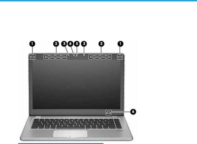
Display
Component |
Description |
|
|
|
|
(1) |
WLAN antennas (2)* (select models only) |
Send and receive wireless signals to communicate with wireless local |
|
|
area networks (WLAN). |
|
|
|
(2) |
WWAN antennas (2)* (select models only) |
Send and receive wireless signals to communicate with wireless wide |
|
|
area networks (WWAN). |
|
|
|
(3) |
Internal microphones (2) |
Record sound. |
|
|
|
(4) |
Webcam light (select models only) |
On: The webcam is in use. |
|
|
|
(5) |
Webcam (select models only) |
Records video and captures photographs. Some models allow you to |
|
|
video conference and chat online using streaming video. |
|
|
To use the webcam: |
|
|
Windows 7: Select Start > All Programs > Communication and Chat |
|
|
> CyberLink YouCam. |
|
|
Windows 8.1: Access HP Support Assistant. To access HP Support |
|
|
Assistant, from the Start screen, select the HP Support Assistant |
|
|
app. |
|
|
Windows 10: Type camera in the taskbar search box, and then |
|
|
select Camera. |
|
|
|
(6) |
Internal display switch |
Turns o the display or initiates Sleep if the display is closed while |
|
|
the power is on. |
Display 5
Component |
Description |
|
|
|
NOTE: The display switch is not visible from the outside of the |
|
computer. |
*The antennas are not visible from the outside of the computer. For optimal transmission, keep the areas immediately around the antennas free from obstructions. For wireless regulatory notices, see the section of the Regulatory, Safety, and Environmental Notices that applies to your country or region. To access this guide:
Windows 7: Select Start > Help and Support > User Guides.
Windows 8.1: From the Start screen, type support, and then select the HP Support Assistant app.
Windows 10: Select Start, select All apps, select HP Help and Support, and then select HP Documentation.
Top
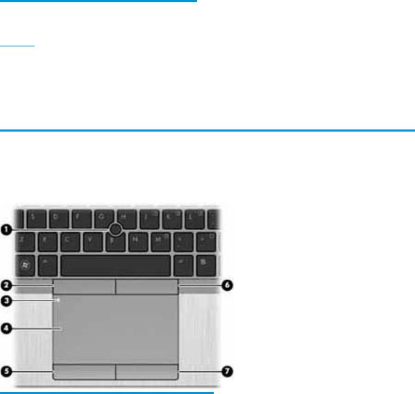
TouchPad
Component |
|
Description |
|
|
|
(1) |
Pointing stick |
Moves the pointer and selects or activates items on the screen. |
|
|
|
(2) |
Left pointing stick button |
Functions like the left button on an external mouse. |
|
|
|
(3) |
TouchPad on/o button |
Turns the TouchPad on and o . |
|
|
|
(4) |
TouchPad zone |
Moves the pointer and selects or activates items on the screen. |
|
|
|
(5) |
Left TouchPad button |
Functions like the left button on an external mouse. |
|
|
|
(6) |
Right pointing stick button |
Functions like the right button on an external mouse. |
|
|
|
(7) |
Right TouchPad button |
Functions like the right button on an external mouse. |
|
|
|
6 Chapter 2 External component identi cation
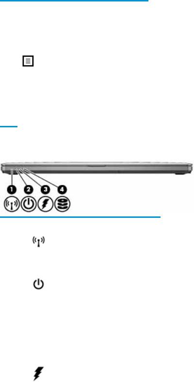
Lights
Component |
|
Description |
|
|
|
|
|
(1) |
Power light |
● |
On: The computer is on. |
|
|
● |
Blinking: The computer is in the Sleep state, a power-saving |
|
|
|
state. The computer shuts o power to the display and |
|
|
|
other unneeded components. |
|
|
● |
The computer is o or in Hibernation. Hibernation is a |
|
|
|
power-saving state that uses the least amount of power. |
|
|
NOTE: For select models, the Intel® Rapid Start Technology |
|
|
|
feature is enabled at the factory. Rapid Start Technology allows |
|
|
|
your computer to resume quickly from inactivity. |
|
|
|
|
|
(2) |
Microphone mute light |
● |
Amber: microphone sound is o . |
|
|
● |
microphone sound is on. |
|
|
|
|
(3) |
Num lock light |
On: Num lock is on. |
|
|
|
|
|
(4) |
Wireless light |
White: An integrated wireless device, such as a wireless local area |
|
|
|
network (WLAN) device and/or a Bluetooth® device, is on. |
|
|
|
NOTE: On some models, the wireless light is amber when all |
|
|
|
wireless devices are o . |
|
|
|
|
|
(5) |
Mute light |
● |
Amber: Computer sound is o . |
|
|
● |
White: Computer sound is on. |
|
|
|
|
(6) |
Caps lock light |
White: Caps lock is on, which switches the keys to all capital |
|
|
|
letters. |
|
|
|
|
|
(7) |
TouchPad light |
● |
Amber: The TouchPad is o . |
|
|
● |
The TouchPad is on. |
|
|
|
|
Top 7
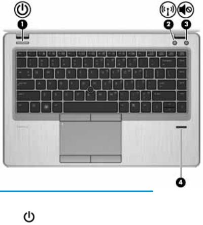
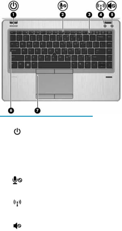
Buttons, speakers, and ngerprint reader (select models only)
Component |
|
Description |
|
|
|
|
|
(1) |
Power button |
● |
When the computer is o , press the button to turn on the |
|
|
|
computer. |
|
|
● |
When the computer is on, press the button briefly to initiate |
|
|
|
Sleep. |
|
|
● |
When the computer is in the Sleep state, press the button |
|
|
|
briefly to exit Sleep. |
|
|
● |
When the computer is in Hibernation, press the button |
|
|
|
briefly to exit Hibernation. |
CAUTION: Pressing and holding down the power button will result in the loss of unsaved information.
If the computer has stopped responding and Windows shutdown procedures are ine ective, press and hold the power button for at least 5 seconds to turn o the computer.
NOTE: For select models, the Intel® Rapid Start Technology feature is enabled at the factory. Rapid Start Technology allows your computer to resume quickly from inactivity.
To learn more about your power settings, see your power options:
Windows 7: Select Start > Control Panel > System and Security
> Power Options.
Windows 8.1: From the Start screen, type power, select Power and sleep settings, and then select Power and sleep from the list of applications.
Windows 10: Type power in the taskbar search box, and then select Power and sleep settings.
8 Chapter 2 External component identi cation
Component |
|
Description |
|
|
|
|
|
– or – |
|
|
Right-click the Start button, and then select Power Options. |
|
|
|
(2) |
Wireless button |
Turns the wireless feature on or o but does not establish a |
|
|
wireless connection. |
|
|
|
(3) |
Volume mute button |
Mutes and restores speaker sound. |
|
|
|
(4) |
Fingerprint reader (select models only) |
Allows a ngerprint logon to Windows, instead of a password |
|
|
logon. |
|
|
|
Keys
Component |
|
Description |
|
|
|
(1) |
esc key |
Displays system information when pressed in combination with |
|
|
the fn key. |
|
|
|
(2) |
fn key |
Executes frequently used system functions when pressed in |
|
|
combination with a function key, the num lk key, the esc key, or |
|
|
the b key. |
|
|
|
(3) |
Windows key |
Windows 7: Displays the Windows Start menu. |
|
|
Windows 8.1: Returns you to the Start screen from an open app |
|
|
or the Windows desktop. |
|
|
NOTE: Pressing the Windows key again will return you to the |
|
|
previous screen. |
|
|
Windows 10: Opens the Windows Start menu. |
|
|
NOTE: Pressing the Windows key again will close the Start |
|
|
menu. |
|
|
|
(4) |
Function keys |
Execute frequently used system functions when pressed in |
|
|
combination with the fn key. |
|
|
|
Top 9
Component |
|
Description |
|
|
|
(5) |
Embedded numeric keypad |
When the keypad is turned on, it can be used like an external |
|
|
numeric keypad. |
|
|
Each key on the keypad performs the function indicated by the |
|
|
icon in the upper-right corner of the key. |
|
|
|
(6) |
Windows applications key |
Windows 7: Displays a shortcut menu for items beneath the |
|
|
cursor. |
|
|
Windows 8.1: Displays options for a selected object. |
|
|
Windows 10: Displays options for a selected object. |
|
|
|
(7) |
num lk key |
Turns the embedded numeric keypad on and o when pressed in |
|
|
combination with the fn key. |
Alternates between the navigational and numeric functions on the integrated numeric keypad.
Front
Component |
|
Description |
|
|
|
|
|
(1) |
Wireless light |
White: An integrated wireless device, such as a wireless |
|
|
|
local area network (WLAN) device and/or a Bluetooth® |
|
|
|
device, is on. |
|
|
|
NOTE: On some models, the wireless light is amber when |
|
|
|
all wireless devices are o . |
|
|
|
|
|
(2) |
Power light |
● |
On: The computer is on. |
|
|
● |
Blinking: The computer is in the Sleep state, a power- |
|
|
|
saving state. The computer shuts o power to the |
|
|
|
display and other unneeded components. |
|
|
● |
The computer is o or in Hibernation. |
|
|
|
Hibernation is a power-saving state that uses the |
|
|
|
least amount of power. |
|
|
NOTE: For select models, the Intel® Rapid Start |
|
|
|
Technology feature is enabled at the factory. Rapid Start |
|
|
|
Technology allows your computer to resume quickly from |
|
|
|
inactivity. |
|
|
|
|
|
(3) |
AC adapter/Battery light |
● |
White: The computer is connected to external power |
|
|
|
and the battery is charged from 90 to 99 percent. |
|
|
● |
Amber: The computer is connected to external power |
|
|
|
and the battery is charged from 0 to 89 percent. |
|
|
● |
Blinking amber: A battery that is the only available |
|
|
|
power source has reached a low battery level. When |
10 Chapter 2 External component identi cation

Component |
|
Description |
|
|
|
|
|
|
|
|
the battery reaches a critical battery level, the |
|
|
|
battery light begins blinking rapidly. |
|
|
● |
The battery is fully charged. |
|
|
|
|
(4) |
Hard drive light |
● |
Blinking white: The hard drive is being accessed. |
|
|
● |
Amber: HP 3D DriveGuard has temporarily parked the |
|
|
|
hard drive. |
|
|
|
|
Left
Component |
|
Description |
|
|
|
(1) |
Power connector |
Connects an AC adapter. |
|
|
|
(2) |
Vent |
Enables airflow to cool internal components. |
|
|
NOTE: The computer fan starts up automatically to cool |
|
|
internal components and prevent overheating. It is normal for |
|
|
the internal fan to cycle on and o during routine operation. |
|
|
|
(3) |
Security cable slot |
Attaches an optional security cable to the computer. |
|
|
NOTE: The security cable is designed to act as a deterrent, but |
|
|
it may not prevent the computer from being mishandled or |
|
|
stolen. |
|
|
|
(4) |
USB 3.0 charging (powered) port |
Connects an optional USB device, such as a keyboard, mouse, |
|
|
external drive, printer, scanner or USB hub. Standard USB ports |
|
|
will not charge all USB devices or will charge using a low current. |
|
|
Some USB devices require power and require you to use a |
|
|
powered port. |
|
|
NOTE: USB charging ports can also charge select models of |
|
|
cell phones and MP3 players, even when the computer is o . |
|
|
|
(5) |
Audio-out (headphone)/Audio-in (microphone) |
Connects optional powered stereo speakers, headphones, |
|
jack |
earbuds, a headset, or a television audio cable. Also connects an |
|
|
optional headset microphone. This jack does not support |
|
|
optional microphone-only devices. |
WARNING! To reduce the risk of personal injury, adjust the volume before putting on headphones, earbuds, or a headset. For additional safety information, see the Regulatory, Safety, and Environmental Notices. To access this guide:
Left 11
Component |
Description |
NOTE: Windows 7: Select Start > Help and Support > User
Guides.
Windows 8.1:
From the Start screen, type support, and then select the HP
Support Assistant app.
‒ or –
From the Windows desktop, click the question mark icon in the noti cation area, at the far right of the taskbar.
Windows 10:
Select Start, select All apps, select HP Help and Support, and then select HP Documentation.
NOTE: When a device is connected to the jack, the computer speakers are disabled.
Be sure that the device cable has a 4-conductor connector that supports both audio-out (headphone) and audio-in (microphone).
(6) |
Smart card reader |
Supports optional Smart cards. |
|
|
|
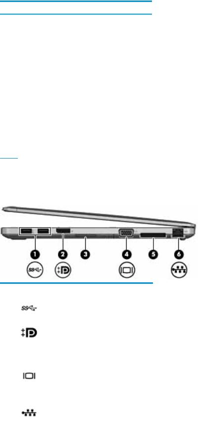
Right
Component |
|
Description |
|
|
|
|
|
(1) |
USB 3.0 ports (2) |
Each USB 3.0 port connects an optional USB device, such as a |
|
|
|
keyboard, mouse, external drive, printer, scanner or USB hub. |
|
|
|
|
|
(2) |
DisplayPort |
Connects an optional digital display device, such as a high- |
|
|
|
performance monitor or projector. |
|
|
|
|
|
(3) |
Memory card reader |
Reads optional memory cards that store, manage, share, or |
|
|
|
access information. |
|
|
|
|
|
(4) |
External monitor port |
Connects an external VGA monitor or projector. |
|
|
|
|
|
(5) |
Docking connector |
Connects an optional docking device. |
|
|
|
|
|
(6) |
RJ-45 (network) jack/lights |
Connects a network cable. |
|
|
|
● |
Green (right): The network is connected. |
|
|
● |
Amber (left): The network is showing activity. |
|
|
|
|
12 Chapter 2 External component identi cation
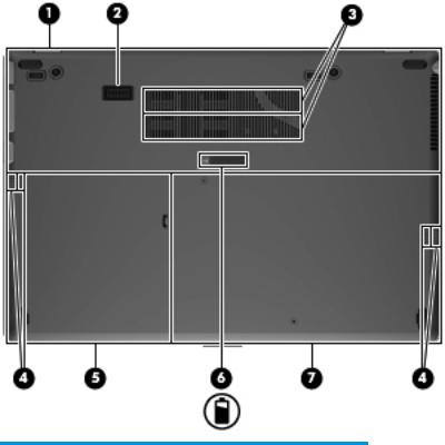
Bottom
Component |
|
Description |
|
|
|
(1) |
Wireless and memory module |
Contains the wireless and memory modules. |
|
compartment |
CAUTION: To prevent an unresponsive system, replace |
|
|
|
|
|
the wireless module only with a wireless module |
|
|
authorized for use in the computer by the governmental |
|
|
agency that regulates wireless devices in your country or |
|
|
region. If you replace the module and then receive a |
|
|
warning message, remove the module to restore computer |
|
|
functionality, and then contact support through HP |
|
|
Support Assistant. |
|
|
To access Help and Support in Windows 7, select Start > |
|
|
Help and Support. |
|
|
To access HP Support Assistant in Windows 8.1, from the |
|
|
Start screen, select the HP Support Assistant app. |
|
|
Windows 10: Type support in the taskbar search box, |
|
|
and then select the HP Support Assistant app. |
|
|
– or – |
|
|
Click the question mark icon in the taskbar. |
|
|
|
(2) |
Travel battery connector |
Connects an optional travel battery. |
|
|
|
(3) |
Vents (2) |
Enable airflow to cool internal components. |
|
|
NOTE: The computer fan starts up automatically to cool |
|
|
internal components and prevent overheating. It is normal |
|
|
for the internal fan to cycle on and o during routine |
|
|
operation. |
|
|
|
Bottom 13

Component |
|
Description |
|
|
|
(4) |
Speakers (2) |
Produce sound. |
|
|
|
(5) |
Hard drive bay |
Contains the hard drive. |
|
|
|
(6) |
Battery release latch |
Releases the battery from the battery bay. |
|
|
|
(7) |
Battery bay and SIM slot |
Holds the battery. Supports a wireless subscriber identity |
|
|
module (SIM). The SIM slot is located inside the battery |
|
|
bay. |
|
|
|
14 Chapter 2 External component identi cation
Labels
The labels affixed to the computer provide information you may need when you troubleshoot system problems or travel internationally with the computer.
 IMPORTANT: Check the following locations for the labels described in this section: the bottom of the computer, inside the battery bay, under the service door, or on the back of the display.
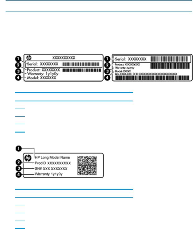
●Service label—Provides important information to identify your computer. When contacting support, you will probably be asked for the serial number, and possibly for the product number or the model number. Locate these numbers before you contact support.
Your service label will resemble one of the examples shown below. Refer to the illustration that most closely matches the service label on your computer.
Component
(1)Serial number
(2)Product number
(3)Warranty period
(4)Model number (select products only)
Component
(1)Model name (select products only)
(2)Product number
(3)Serial number
(4)Warranty period
●Regulatory label(s)—Provide(s) regulatory information about the computer.
●Wireless certi cation label(s)—Provide(s) information about optional wireless devices and the approval markings for the countries or regions in which the devices have been approved for use.
Labels 15

3Illustrated parts catalog
 NOTE: HP continually improves and changes product parts. For complete and current information on supported parts for your computer, go to http://partsurfer.hp.com, select your country or region, and then follow the on-screen instructions.


 NOTE: Details about your computer, including model, serial number, product key, and length of warranty, are on the service tag at the bottom of your computer. See Illustrated parts catalog on page 16 for details.
16 Chapter 3 Illustrated parts catalog

Computer major components
Computer major components 17

Item |
Component |
Spare part number |
(1)Display assembly: The display assembly is spared at the subcomponent level only. For more display assembly spare part information, see Display assembly subcomponents on page 20.
(2) |
Keyboard (backlit; includes keyboard cable and pointing stick cable): |
785648-xx1 |
|
NOTE: For a list of keyboard country codes, see Keyboard on page 45. |
|
|
|
|
(3) |
Top cover |
|
|
|
|
|
With ngerprint reader board |
748352-001 |
|
|
|
|
Without ngerprint reader board |
748353-001 |
|
|
|
|
Touchpad assembly (not illustrated) |
822825-001 |
|
|
|
(4) |
Speakers (right and left; include cables) |
702869-001 |
|
|
|
(5) |
AC power connector |
702875-001 |
|
|
|
(6) |
Smart Card reader (includes cable) |
769707-001 |
|
|
|
(7) |
Fan (includes cable) |
702859-001 |
(8)System board (includes processor and replacement thermal material): All system boards use the following part numbers:
xxxxxx-001: Windows 7 or non-Windows operating systems xxxxxx-501: Windows 8.1 Standard operating system xxxxxx-601: Windows 8.1 or Windows 10 operating system
|
● |
Intel Core i7-4650U processor |
769720-xxx |
|
|
|
|
|
● |
Intel Core i7-4600U processor |
769719-xxx |
|
|
|
|
|
● |
Intel Core i5-4310U processor |
769718-xxx |
|
|
|
|
|
● |
Intel Core i5-4210U processor |
769717-xxx |
|
|
|
|
|
Plastics Kit, includes: |
702877-001 |
|
|
|
|
|
(9a) |
SD card insert |
|
|
|
|
|
|
(9b) |
Hard drive cover |
|
|
|
|
|
|
(10) |
Heat sink (includes replacement thermal material): |
769708-001 |
|
|
|
|
|
(11) |
RTC battery |
702853-001 |
|
|
|
|
|
(12) |
Fingerprint reader board (includes cable) |
702845-001 |
|
|
|
|
|
(13) |
Base enclosure |
702863-001 |
|
|
|
|
|
(14) |
Service cover |
704441-001 |
|
|
|
|
|
|
Service cover, RCTO |
713547-001 |
|
|
|
|
|
(15) |
Memory modules (PC3L-12800, 1600-MHz): |
|
|
|
|
|
|
|
4-GB |
|
691740-001 |
|
|
|
|
|
8-GB |
|
693374-001 |
|
|
|
|
(16) |
WLAN module: |
|
|
|
|
|
|
|
Intel Dual Band Wireless-AC 7260 802.11 AC 2x2 WiFi + BT 4.0 Combo Adapter |
710663-001 |
|
|
|
|
|
18 Chapter 3 Illustrated parts catalog
Loading...