


HP EliteBook Folio 1040 G1 Notebook PC
Maintenance and Service Guide
© Copyright 2013 Hewlett-Packard
Development Company, L.P.
Bluetooth is a trademark owned by its proprietor and used by Hewlett-Packard Company under license. Intel and Core are U.S. registered trademarks of Intel Corporation. Microsoft and Windows are U.S. registered trademarks of the Microsoft group of companies.SD Logo is a trademark of
its proprietor.
The information contained herein is subject to change without notice. The only warranties for HP products and services are set forth in the express warranty statements accompanying such products and services. Nothing herein should be construed as constituting an additional warranty. HP shall not be liable for technical or editorial errors or omissions contained herein.
First Edition: December 2013
Document Part Number: 738834-001
Product notice
This guide describes features that are common to most models. Some features may not be available on your computer.
Not all features are available on all editions of Windows 8. This computer may require upgraded and/or separately purchased hardware, drivers, and/or software to take full advantage of Windows 8 functionality. See http://www.microsoft.com for details.
This computer may require upgraded and/ or separately purchased hardware and/or a DVD drive to install the Windows 7 software and take full advantage of Windows 7 functionality. See http://windows.microsoft.com/en-us/ windows7/get-know-windows-7 for details.

Safety warning notice
WARNING! To reduce the possibility of heat-related injuries or of overheating the device, do not place the device directly on your lap or obstruct the device air vents. Use the device only on a hard, flat surface. Do not allow another hard surface, such as an adjoining optional printer, or a soft surface, such as pillows or rugs or clothing, to block airflow. Also, do not allow the AC adapter to contact the skin or a soft surface, such as pillows or rugs or clothing, during operation. The device and the AC adapter comply with the user-accessible surface temperature limits defined by the International Standard for Safety of Information Technology Equipment (IEC 60950).
iii
iv Safety warning notice

Table of contents
1 Product description ....................................................................................................................................... |
1 |
2 External component identification ................................................................................................................. |
5 |
Display ................................................................................................................................................................... |
5 |
Top ......................................................................................................................................................................... |
6 |
ForcePad .............................................................................................................................................. |
6 |
Lights ................................................................................................................................................... |
7 |
Buttons and fingerprint reader ........................................................................................................... |
8 |
Keys ..................................................................................................................................................... |
9 |
Windows models ............................................................................................................... |
9 |
Linux models ................................................................................................................... |
10 |
Left ....................................................................................................................................................................... |
11 |
Right ..................................................................................................................................................................... |
12 |
Bottom ................................................................................................................................................................. |
13 |
Service tag and PCID label ................................................................................................................................... |
14 |
Service tag ......................................................................................................................................... |
14 |
PCID label ........................................................................................................................................... |
15 |
3 Illustrated parts catalog .............................................................................................................................. |
16 |
Computer major components ............................................................................................................................. |
16 |
Display assembly subcomponents ..................................................................................................................... |
19 |
Plastics Kit ........................................................................................................................................................... |
20 |
Mass storage devices .......................................................................................................................................... |
20 |
Miscellaneous parts ............................................................................................................................................. |
21 |
Sequential part number listing ........................................................................................................................... |
22 |
4 Removal and replacement procedures preliminary requirements .................................................................... |
26 |
Tools required ...................................................................................................................................................... |
26 |
Service considerations ........................................................................................................................................ |
26 |
Plastic parts ....................................................................................................................................... |
26 |
Cables and connectors ...................................................................................................................... |
26 |
Drive handling ................................................................................................................................... |
27 |
Grounding guidelines ........................................................................................................................................... |
27 |
Electrostatic discharge damage ....................................................................................................... |
27 |
Packaging and transporting guidelines ......................................................................... |
28 |
Workstation guidelines ................................................................................ |
28 |
v
5 Removal and replacement procedures for Authorized Service Provider parts ................................................... |
30 |
Component replacement procedures ................................................................................................................. |
30 |
Display assembly components (panel, bezel, webcam, microphone) ............................................. |
31 |
Bottom cover ..................................................................................................................................... |
35 |
Display assembly .............................................................................................................................. |
37 |
RTC battery ........................................................................................................................................ |
40 |
Battery ............................................................................................................................................... |
41 |
SSD drive ........................................................................................................................................... |
43 |
Memory module ................................................................................................................................ |
44 |
WWAN module ................................................................................................................................... |
46 |
WLAN module .................................................................................................................................... |
48 |
Keyboard ........................................................................................................................................... |
50 |
ForcePad (Touchpad) ........................................................................................................................ |
53 |
NFC module ....................................................................................................................................... |
55 |
Smart card reader ............................................................................................................................. |
56 |
Power connector ............................................................................................................................... |
58 |
Heat sink/fan assembly .................................................................................................................... |
59 |
System board .................................................................................................................................... |
61 |
Multi-function board ......................................................................................................................... |
64 |
Fingerprint reader board ................................................................................................................... |
65 |
Speaker assembly ............................................................................................................................. |
66 |
SIM slot .............................................................................................................................................. |
67 |
6 Computer Setup (BIOS), MultiBoot, and HP PC Hardware Diagnostics (UEFI) in Windows 8 .................................. |
69 |
Using Computer Setup ......................................................................................................................................... |
69 |
Starting Computer Setup .................................................................................................................. |
69 |
Navigating and selecting in Computer Setup ................................................................................... |
69 |
Restoring factory settings in Computer Setup ................................................................................. |
70 |
Updating the BIOS ............................................................................................................................. |
70 |
Determining the BIOS version ........................................................................................ |
70 |
Downloading a BIOS update ........................................................................................... |
71 |
Using MultiBoot ................................................................................................................................................... |
72 |
About the boot device order ............................................................................................................. |
72 |
Choosing MultiBoot preferences ...................................................................................................... |
72 |
Setting a new boot order in Computer Setup ................................................................. |
72 |
Dynamically choosing a boot device using the f9 prompt ............................................. |
73 |
Setting a MultiBoot Express prompt .............................................................................. |
73 |
Entering MultiBoot Express preferences ....................................................................... |
73 |
Using HP PC Hardware Diagnostics (UEFI) (select models only) ........................................................................ |
73 |
Downloading HP PC Hardware Diagnostics (UEFI) to a USB device .................................................. |
74 |
vi
7 Computer Setup (BIOS), MultiBoot, and HP PC Hardware Diagnostics (UEFI) in Windows 7 .................................. |
75 |
Using Computer Setup ......................................................................................................................................... |
75 |
Starting Computer Setup .................................................................................................................. |
75 |
Navigating and selecting in Computer Setup ................................................................................... |
75 |
Restoring factory settings in Computer Setup ................................................................................. |
76 |
Updating the BIOS ............................................................................................................................. |
76 |
Determining the BIOS version ........................................................................................ |
76 |
Downloading a BIOS update ........................................................................................... |
77 |
Using MultiBoot ................................................................................................................................................... |
78 |
About the boot device order ............................................................................................................. |
78 |
Choosing MultiBoot preferences ...................................................................................................... |
78 |
Setting a new boot order in Computer Setup ................................................................. |
78 |
Dynamically choosing a boot device using the f9 prompt ............................................. |
79 |
Setting a MultiBoot Express prompt .............................................................................. |
79 |
Entering MultiBoot Express preferences ....................................................................... |
79 |
Using HP PC Hardware Diagnostics (UEFI) (select models only) ........................................................................ |
79 |
Downloading HP PC Hardware Diagnostics (UEFI) to a USB device .................................................. |
74 |
8 Computer Setup (BIOS) and Advanced System Diagnostics in Linux .................................................................. |
81 |
Starting Computer Setup ..................................................................................................................................... |
81 |
Using Computer Setup ......................................................................................................................................... |
81 |
Navigating and selecting in Computer Setup ................................................................................... |
81 |
Restoring factory settings in Computer Setup ................................................................................. |
82 |
Updating the BIOS ................................................................................................................................................ |
82 |
Determining the BIOS version ........................................................................................................... |
82 |
Downloading a BIOS update .............................................................................................................. |
83 |
Using Advanced System Diagnostics .................................................................................................................. |
83 |
9 Specifications ............................................................................................................................................. |
85 |
Computer specifications ...................................................................................................................................... |
85 |
35.6-cm (14.0-in) HD+ display specifications ..................................................................................................... |
86 |
35.6-cm (14.0-in) FHD display specifications ..................................................................................................... |
86 |
M.2 solid-state drive specifications .................................................................................................................... |
88 |
10 Backup and recovery in Windows 8 .............................................................................................................. |
89 |
Backing up your information ............................................................................................................................... |
89 |
Performing a system recovery ............................................................................................................................ |
89 |
Using the Windows recovery tools ................................................................................................... |
89 |
Using f11 recovery tools ................................................................................................................... |
90 |
Using Windows operating system media (purchased separately) ................................................... |
91 |
vii
Using Windows Refresh or Windows Reset ...................................................................................... |
91 |
Using HP Software Setup .................................................................................................................. |
91 |
11 Backup and recovery in Windows 7 .............................................................................................................. |
92 |
Creating recovery media and backups ................................................................................................................ |
92 |
Guidelines .......................................................................................................................................... |
92 |
Creating recovery media with HP Recovery Disc Creator ................................................................. |
92 |
Creating recovery media ................................................................................................. |
93 |
Backing up your information ............................................................................................................ |
93 |
Performing a system recovery ............................................................................................................................ |
94 |
Using the Windows recovery tools ................................................................................................... |
94 |
Using f11 recovery tools (select models only) ................................................................................. |
95 |
Using Windows 7 operating system media ...................................................................................... |
95 |
12 Backup and Recovery in Linux ..................................................................................................................... |
97 |
Creating backups ................................................................................................................................................. |
97 |
Backing up your information ............................................................................................................................... |
97 |
Performing a system recovery ............................................................................................................................ |
98 |
USB Recovery option (select models only) ......................................................................................................... |
98 |
Remove everything and reinstall SLED ............................................................................................................... |
99 |
13 Statement of Volatility ............................................................................................................................ |
101 |
Non-volatile memory usage ............................................................................................................................. |
102 |
Questions and answers ..................................................................................................................................... |
104 |
14 Power cord set requirements .................................................................................................................... |
106 |
Requirements for all countries ......................................................................................................................... |
106 |
Requirements for specific countries and regions ............................................................................................. |
106 |
15 Recycling ................................................................................................................................................ |
108 |
Battery ............................................................................................................................................................... |
108 |
Display ............................................................................................................................................................... |
108 |
Index ........................................................................................................................................................... |
114 |
viii

1 Product description
Category |
Description |
|
|
|
|
Product Name |
HP EliteBook 1040 G1 Notebook PC |
|
|
|
|
Processors |
Intel® Core® processors: |
|
|
● i7-4650U 1.7-GHz (max turbo frequency 3.3-GHz), 4-MB L3 Cache, 15W |
|
|
● i7-4600U 2.1-GHz (max turbo frequency 3.3-GHz), 4-MB L3 Cache, 15W |
|
|
● i5-4300U 1.9-GHz (max turbo frequency 2.9-GHz), 3-MB L3 Cache, 15W |
|
|
● i5-4200U 1.6-GHz (max turbo frequency 2.6-GHz), 3-MB L3 Cache, 15W |
|
|
|
|
Chipset |
Mobile Intel QM87 |
|
|
|
|
Graphics |
Intel HD Graphics 4400 (i5-4200U, i5-4300U, i7-4600U) |
|
|
Intel HD Graphics 5000 (i7-4650U) |
|
|
|
|
Panels |
35.6-cm (14.0-in), DP 1.2 slim, high-definition+ (HD+), AntiGlare (AG), SVA |
|
|
(1600×900) display with and without webcam and WWAN |
|
|
35.6-cm (14.0-in), 3.0-mm, FHD, AG, UWVA (1600×900) display with and without |
|
|
webcam and WWAN |
|
|
All display assemblies include two wireless local area network (WLAN) antenna |
|
|
cables and NFC antenna |
|
|
WWAN models include two wireless wide area network (WWAN) antenna cables |
|
|
|
|
Memory |
One service provider-accessible/upgradable memory module slot |
|
|
4-GB memory integrated into system board |
|
|
DDR3L PC3L-12800-(1600 MHz) dual channel support |
|
|
NOTE: DDR3 memory is not supported. Only DDR3L memory is supported. |
|
|
Supports 8-GB of system RAM in the following configurations: |
|
|
● 8-GB (4-GB integrated + 4-GB SODIMM) |
|
|
● |
4-GB (4-GB integrated) |
|
|
|
Primary storage |
Supports M.2 SSD SS 2280 |
|
|
Serial ATA III |
|
|
Supports the following M.2 SSDs: |
|
|
● |
256-GB |
|
● |
180-GB |
|
● |
128-GB |
|
|
|
Audio and video |
Two stereo speakers |
|
|
|
|
|
HD audio with DTS Studio Sound |
|
|
|
|
|
Integrated 720p webcam (supports no camera option) |
|
|
|
|
|
Integrated dual-array microphone |
|
|
|
|
1

Category |
Description |
|
|
|
|
Ethernet |
Intel I218LM Gigabit Network Connection |
|
|
S3/S4/S5 wake on LAN |
|
|
|
|
Wireless |
WLAN |
|
|
Integrated wireless local area network (WLAN) options by way of wireless module |
|
|
Two WLAN antennas built into display assembly |
|
|
Support for the following WLAN formats: |
|
|
● |
Intel Dual Band Wireless-N 7260AN 802.11 a/b/g/n 2x2 WiFi + BT4.0 |
|
● |
Intel Dual Band Wireless-AC 7260 802.11 ac 2x2 WiFi + BT 4.0 |
|
● |
Intel Dual Band Wireless-N 7260NB 802.11 a/b/g/n 2x2 WiFi |
|
Supports no WLAN option |
|
|
|
|
|
WWAN |
|
|
Integrated wireless wide area network (WWAN) options by way of wireless module |
|
|
Two world-wide/5-band WWAN antennas built into display assembly only |
|
|
configured on WWAN models |
|
|
Secured by subscriber identity module (SIM, user-accessible on the side of the |
|
|
computer) |
|
|
Support for the following WWAN formats: |
|
|
● |
HP lt4111 LTE/EV-DO/HSPA+ Mobile Broadband Module |
|
● |
HP lt4112 LTE/HSPA+ Gobi 4G Module |
|
● |
HP hs3110 HSPA+ Mobile Broadband Module |
|
Supports no WWAN option |
|
|
|
|
|
NFC |
|
|
Integrated NFC module |
|
|
NFC antenna 100% attached to all models |
|
|
Supports no NFC option |
|
|
|
|
External media cards |
Micro SD Media Reader Slot - supports SD, SDHC, SDXC |
|
|
|
|
Ports |
Headphone/Microphone Combo |
|
|
DisplayPort 1.2 |
|
|
Docking connector |
|
|
Multi-Pin AC port |
|
|
USB 3.0 port (1) |
|
|
USB 3.0 charging/powered port (1) |
|
|
|
|
Keyboard/pointing devices |
Keyboard |
|
|
Dura keys, backlit, spill-resistant with drain |
|
ForcePad
Gestures enabled by default: two-finger scrolling, two-finger pinch-zoom
Taps enabled by default
2 Chapter 1 Product description
Category |
Description |
|
|
|
|
|
ForcePad supports 2-way scroll |
|
|
Glass with chemical etched surface |
|
|
|
|
Power requirements |
AC adapters: |
|
|
45-W HP Smart AC adapter |
|
|
45-W HP Smart AC adapter |
|
|
65-W HP Smart AC adapter |
|
|
65-W Slim AC adapter |
|
|
|
|
|
Battery: |
|
|
Supports a 6-cell, 42-Whr battery |
|
|
|
|
Security |
Security lock |
|
|
Fingerprint reader |
|
|
Supports Trusted Platform Module (TPM) 1.2 (Infineon, soldered down) |
|
|
Integrated Smart Card reader (active) |
|
|
Full volume encryption |
|
|
Preboot authentication (password, smart card) |
|
|
|
|
Operating system |
Preinstalled: |
|
|
● |
Windows® 7 Home Premium 64and 32-bit |
|
● |
Windows 7 Professional 64and 32-bit |
|
● |
Windows 7 Professional MSNA 64and 32-bit (only for China and Asia/Pacific) |
|
● |
Windows 7 Home Basic 32 |
|
● |
Windows 8.1 Professional 64 DPK with Windows 7 Professional 32 or 64 image |
|
● |
Windows 8.1 Professional 64 DPK with Windows 7 Professional MSNA 32 or 64 |
|
|
image (only for China and Asia/Pacific) |
|
● |
Windows 8.1 China 64 |
|
● |
Windows 8.1 Emerging Markets 64 |
|
● |
Windows 8.1 Multilingual 64 |
|
● |
Windows 8.1 Professional 64 |
|
● |
Windows 8.1 Professional 64 MSNA |
|
● |
FreeDOS 2.0 |
|
● |
SUSE Linux SLED 11 64-bit, Service Pack 2 (not available with WWAN) |
|
|
|
|
Restore media–DR-DVD: |
|
|
● |
Windows 7 |
|
● |
Windows 8.1 |
|
|
|
|
Restore media–SR-DVD: |
|
|
● |
SuSE Linux Enterprise (SLED) 64-bit, Service Pack 2 |
|
|
|
|
Restore media–OS-DVD: |
|
|
● |
Windows 8.1 Professional 64-bit |
3

Category |
Description |
|
|
|
|
|
● |
Windows 8.1 64-bit |
|
● |
Windows 8.1 Country Specific 64-bit |
|
● |
Windows 8.1 Emerging Market 64-bit |
|
● |
Windows 7 Home Premium 64and 32-bit |
|
● |
Windows 7 Professional 64and 32-bit |
|
|
|
|
Certified: |
|
|
● |
SuSE Linux Enterprise (SLED) 64-bit Service Pack 2 |
|
● |
Microsoft WHQL |
|
|
|
|
Web-only support: |
|
|
● |
Windows 8.1 Enterprise 64 |
|
● |
Windows 7 Enterprise 64 and 32 |
|
● |
Windows 7 Ultimate 64 and 32 |
|
|
|
Serviceability |
End user replaceable parts: |
|
|
● |
AC adapter |
|
|
|
4 Chapter 1 Product description
2 External component identification
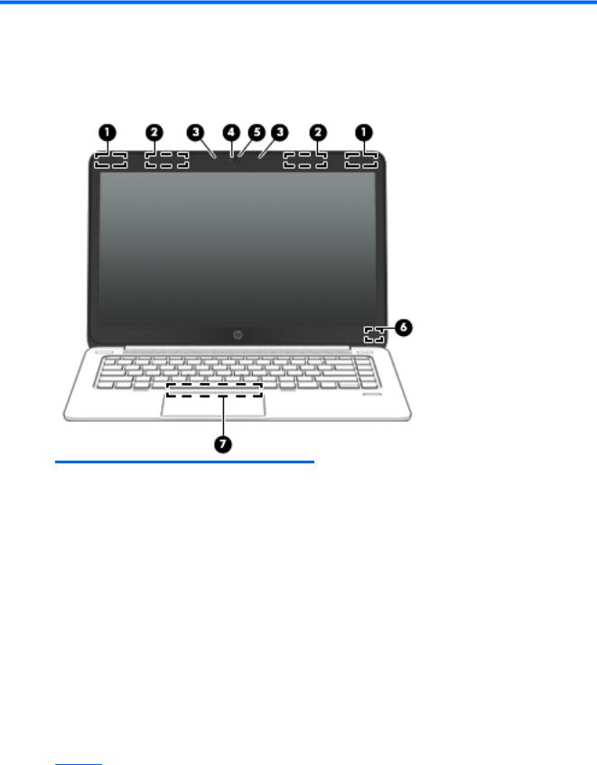
Display
Component |
Description |
|
|
|
|
(1) |
WLAN antennas (2)* (select models only) |
Send and receive wireless signals to communicate with wireless local |
|
|
area networks (WLAN). |
|
|
|
(2) |
WWAN antennas (2)* (select models only) |
Send and receive wireless signals to communicate with wireless wide |
|
|
area networks (WWAN). |
|
|
|
(3) |
Internal microphones (2) |
Record sound. |
|
|
|
(4) |
Webcam light (select models only) |
On: The webcam is in use. |
|
|
|
(5) |
Webcam (select models only) |
Records video and captures still photographs. |
|
|
For information on using the webcam in Windows 8, access HP |
|
|
Support Assistant. To access HP Support Assistant on the Start |
|
|
screen, select the HP Support Assistant app. |
|
|
For information on using the webcam in Windows 7, select Start > All |
|
|
Programs > Communication and Chat > Cyberlink YouCam. |
|
|
|
(6) |
Internal display switch |
Turns off the display or initiates Sleep if the display is closed while |
|
|
the power is on. |
NOTE: The display switch is not visible on the outside of the computer.
Display 5
Component |
Description |
|
|
|
|
(7) |
Near Field Communication (NFC) antenna* (select |
Send and receive wireless signals to communicate and transfer data/ |
|
models only) |
info to and from your Near Field Communication (NFC)-compatible |
|
|
devices. |
*The antennas are not visible on the outside of the computer. For optimal transmission, keep the areas immediately around the antennas free from obstructions. To see wireless regulatory notices, see the section of the Regulatory, Safety, and Environmental Notices that applies to your country or region. To access the user guides, select the HP Support Assistant app on the Start screen, select My computer, and then select User guides. To access the user guides in Windows 7, select Start > Help and Support > User Guides.
Top
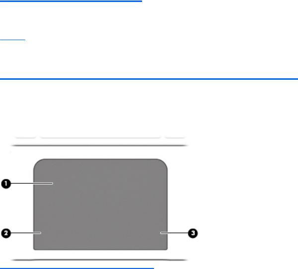
ForcePad
Component |
|
Description |
|
|
|
(1) |
ForcePad zone |
Moves the pointer and selects or activates items on the screen. |
|
|
|
(2) |
Left ForcePad zone |
Functions like the left button on an external mouse. |
|
|
|
(3) |
Right ForcePad zone |
Functions like the right button on an external mouse. |
|
|
|
6 Chapter 2 External component identification
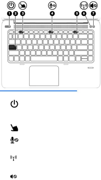
Lights
Component |
|
Description |
|
|
|
|
|
(1) |
Power light |
● |
On: The computer is on. |
|
|
● |
Blinking: The computer is in the Sleep state. |
|
|
● |
Off: The computer is off. |
|
|
|
|
(2) |
Caps lock light |
On: Caps lock is on. |
|
|
|
|
|
(3) |
ForcePad light |
● |
Amber: The ForcePad is off. |
|
|
● |
Off: The ForcePad is on. |
|
|
|
|
(4) |
Microphone mute light |
● |
Amber: Microphone sound is off. |
|
|
● |
Off: Microphone sound is on. |
|
|
|
|
(5) |
Num lock light |
On: Num lock is on. |
|
|
|
|
|
(6) |
Wireless light |
● |
White: An integrated wireless device, such as a wireless |
|
|
|
local area network (WLAN) device and/or a Bluetooth® |
|
|
|
device, is on. |
|
|
● |
Amber: All wireless devices are off. |
|
|
|
|
(7) |
Mute light |
● |
Amber: Computer sound is off. |
|
|
● |
Off: Computer sound is on. |
|
|
|
|
Top 7
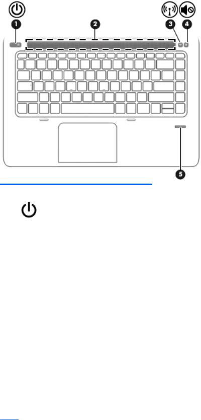
Buttons and fingerprint reader
Component |
|
Description |
|
|
|
|
|
(1) |
Power button |
● |
When the computer is off, press the button to turn on the |
|
|
|
computer. |
|
|
● |
When the computer is on, press the button briefly to initiate |
|
|
|
Sleep. |
|
|
● |
When the computer is in the Sleep state, press the button |
|
|
|
briefly to exit Sleep. |
|
|
● |
When the computer is in Hibernation, press the button |
|
|
|
briefly to exit Hibernation. |
CAUTION: Pressing and holding down the power button will result in the loss of unsaved information.
If the computer has stopped responding and Windows® shutdown procedures are ineffective, press and hold the power button for at least 5 seconds to turn off the computer.
If the computer has stopped responding and the previous shutdown procedures are ineffective, press and hold the power button + volume mute button for at least 5 seconds to perform a hardware reset turning off the computer.
To learn more about your power settings in Windows 8, see your power options. From the Start screen, type power, select Power and sleep settings, and then select Power and sleep from the list of applications.
To learn more about your power settings in Windows 7: Select
Start > Control Panel > System and Security > Power Options.
To learn more about your power settings in Linux: Select
Computer > Control Center. In the left pane, click System, and then click Power Management in the right pane.
8 Chapter 2 External component identification
Component |
|
Description |
|
|
|
(2) |
Speaker grill |
Produce sound. |
|
|
|
(3) |
Wireless button |
Turns the wireless feature on or off but does not establish a |
|
|
wireless connection. |
|
|
|
(4) |
Volume mute button |
Mutes and restores speaker sound. |
|
|
|
(5) |
Fingerprint reader |
Allows a fingerprint logon to Windows, instead of a password |
|
|
logon. |
|
|
|
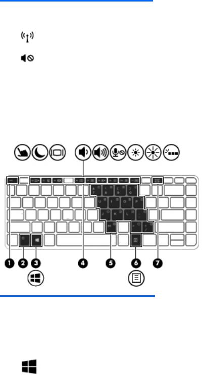
Keys
Windows models
Component |
|
Description |
|
|
|
(1) |
esc key |
Displays system information when pressed in combination with |
|
|
the fn key. |
|
|
|
(2) |
fn key |
Executes frequently used system functions when pressed in |
|
|
combination with a function key, the num lk key, the esc key, or |
|
|
the b key. |
|
|
|
(3) |
Windows button |
Windows 8: Returns you to the Start screen from an open app or |
|
|
the Windows desktop. |
|
|
NOTE: Pressing the Windows button again will return you to |
|
|
the previous screen. |
|
|
Windows 7: Displays the Windows Start menu. |
|
|
|
(4) |
Function keys |
Execute frequently used system functions when pressed in |
|
|
combination with the fn key. |
|
|
|
(5) |
Embedded numeric keypad |
When the keypad is turned on, it can be used like an external |
|
|
numeric keypad. |
Top |
9 |
Component |
|
Description |
|
|
|
|
|
Each key on the keypad performs the function indicated by the |
|
|
icon in the upper-right corner of the key. |
|
|
|
(6) |
Operating system applications key |
Windows 8: Displays options for a selected object. |
|
|
Windows 7 and Linux: Displays a shortcut menu for items |
|
|
beneath the cursor. |
|
|
|
(7) |
num lk key |
Turns the embedded numeric keypad on and off when pressed |
|
|
in combination with the fn key. |
Alternates between the navigational and numeric functions on the integrated numeric keypad.
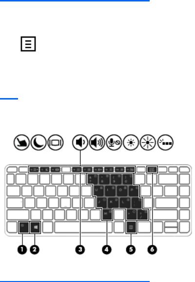
Linux models
Component |
|
Description |
|
|
|
(1) |
esc key |
Displays system information when pressed in combination with |
|
|
the fn key. |
|
|
|
(2) |
fn key |
Executes frequently used system functions when pressed in |
|
|
combination with a function key, the num lk key, the esc key, or |
|
|
the b key. |
|
|
|
(3) |
Function keys |
Execute frequently used system functions when pressed in |
|
|
combination with the fn key. |
|
|
|
(4) |
Embedded numeric keypad |
When the keypad is turned on, it can be used like an external |
|
|
numeric keypad. |
|
|
Each key on the keypad performs the function indicated by the |
|
|
icon in the upper-right corner of the key. |
|
|
|
(5) |
Operating system applications key |
Windows 8: Displays options for a selected object. |
10 Chapter 2 External component identification

Component |
|
Description |
|
|
|
|
|
Displays a shortcut menu for items beneath the cursor. |
|
|
|
(6) |
num lk key |
Turns the embedded numeric keypad on and off when pressed |
|
|
in combination with the fn key. |
|
|
Alternates between the navigational and numeric functions on |
|
|
the integrated numeric keypad. |
|
|
|
Left
Component |
|
Description |
|
|
|
(1) |
Security cable slot |
Attaches an optional security cable to the computer. |
|
|
NOTE: The security cable is designed to act as a deterrent, but |
|
|
it may not prevent the computer from being mishandled or |
|
|
stolen. |
|
|
|
(2) |
Vent |
Enables airflow to cool internal components. |
|
|
NOTE: The computer fan starts up automatically to cool |
|
|
internal components and prevent overheating. It is normal for |
|
|
the internal fan to cycle on and off during routine operation. |
|
|
|
(3) |
USB 3.0 charging port |
Connects an optional USB device. The USB charging port can |
|
|
also charge select models of cell phones and MP3 players, even |
|
|
when the computer is off. |
|
|
|
(4) |
Micro SD memory card reader |
Supports micro Secure Digital (SD) memory cards. |
|
|
|
(5) |
Smart card reader |
Supports optional Smart cards. |
|
|
|
Left 11
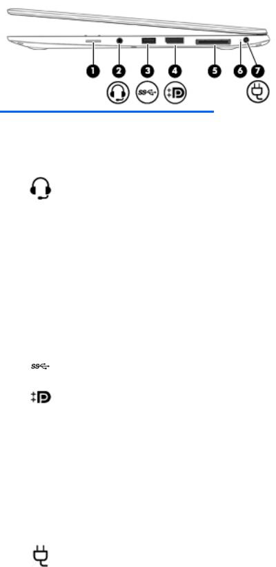
Right
Component |
|
Description |
|
|
|
|
|
(1) |
SIM slot plug (select models only) |
Supports a wireless subscriber identity module (SIM). |
|
|
|
For more information about SIM slot inserts and covers, see SIM |
|
|
|
slot on page 67. |
|
|
|
|
|
(2) |
Audio-out (headphone) jack/Audio-in |
Produces sound when connected to optional powered stereo |
|
|
(microphone) jack |
speakers, headphones, earbuds, a headset, or television audio. |
|
|
|
Also connects an optional headset microphone. |
|
|
|
WARNING! To reduce the risk of personal injury, adjust the |
|
|
|
volume before putting on headphones, earbuds, or a headset. |
|
|
|
For additional safety information, see the Regulatory, Safety, |
|
|
|
and Environmental Notices. To access the user guides in |
|
|
|
Windows 8, select the HP Support Assistant app on the Start |
|
|
|
screen, select My computer, and then select User guides. |
|
|
|
To access the user guides in Windows 7, select Start > Help and |
|
|
|
Support > User Guides. |
|
|
|
NOTE: When a device is connected to the jack, the computer |
|
|
|
speakers are disabled. |
|
|
|
NOTE: Be sure that the device cable has a 4-conductor |
|
|
|
connector that supports both audio-out (headphone) and |
|
|
|
audio-in (microphone). |
|
|
|
|
|
(3) |
USB 3.0 port |
Connect optional USB 3.0 devices and provide enhanced USB |
|
|
|
power performance. |
|
|
|
|
|
(4) |
DisplayPort |
Connects an optional digital display device, such as a high- |
|
|
|
performance monitor or projector. |
|
|
|
|
|
(5) |
Docking connector |
Connects an optional docking device or mini docking station. |
|
|
|
|
|
(6) |
AC adapter/Battery light |
● |
White: The computer is connected to external power and |
|
|
|
the battery is charged from 90 to 99 percent. |
|
|
● |
Amber: The computer is connected to external power and |
|
|
|
the battery is charged from 0 to 90 percent. |
|
|
● |
Blinking amber: A battery that is the only available power |
|
|
|
source has reached a low battery level. When the battery |
|
|
|
reaches a critical battery level, the battery light begins |
|
|
|
blinking rapidly. |
|
|
● |
Off: The battery is fully charged. |
|
|
|
|
(7) |
Power connector |
Connects an AC adapter. |
|
|
|
|
|
12 Chapter 2 External component identification
Bottom
Component |
|
Description |
|
|
|
(1) |
Docking device receptors (2) |
Connects an optional docking device. |
|
|
|
(2) |
Vents (2) |
Enable airflow to cool internal components. |
|
|
NOTE: The computer fan starts up automatically to cool |
internal components and prevent overheating. It is normal for the internal fan to cycle on and off during routine operation.
Bottom 13
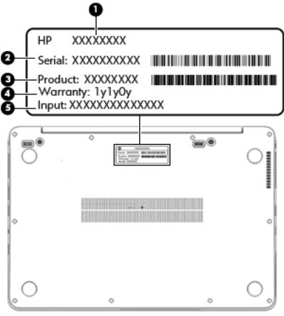
Service tag and PCID label
Service tag
When ordering parts or requesting information, provide the computer serial number and model description provided on the service tag.
●Product name (1). This is the product name affixed to the front of the computer.
●Serial number (s/n) (2). This is an alphanumeric identifier that is unique to each product.
●Part number/Product number (p/n) (3). This number provides specific information about the product's hardware components. The part number helps a service technician to determine what components and parts are needed.
●Warranty period (4). This number describes the duration (in years) of the warranty period for the computer.
●Power ratings (5). This is the power information for the computer.
14 Chapter 2 External component identification
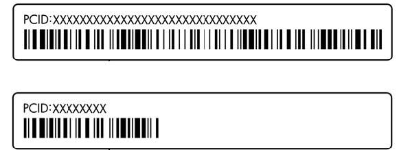
PCID label
The PCID label provides the information required to properly reset the notebook firmware (BIOS) back to factory shipped specifications when replacing the system board. The label may have a different number of characters depending on the operating system on the computer.
Windows 8 models
Non-Windows 8 models
Service tag and PCID label 15

3 Illustrated parts catalog
Computer major components
16 Chapter 3 Illustrated parts catalog

Item |
Component |
Spare part number |
(1)Display assembly: The display assembly is spared at the subcomponent level only. For more display assembly spare part information, see Display assembly subcomponents on page 19.
(2) |
Keyboard (backlit; includes keyboard cable and backlight cable): |
739563-xx1 |
|
|
NOTE: For a detailed list of available keyboards, see Sequential part number listing |
|
|
|
on page 22. |
|
|
|
|
|
|
(3) |
Top cover (with buttons) |
739576-001 |
|
|
|
|
|
(4) |
ForcePad (Touchpad) |
739565-001 |
|
|
|
|
|
(5) |
Smart Card reader (includes cable) |
739566-001 |
|
|
|
|
|
(6) |
Fingerprint reader board (includes bracket and cable) |
739567-001 |
|
|
|
|
|
(7) |
Speakers (includes cable) |
739577-001 |
|
|
|
|
|
(8) |
AC power connector |
749612-001 |
|
|
|
|
|
(9) |
Function board |
739574-001 |
|
|
|
|
|
(10) |
Heat sink/thermal module with fans (includes replacement thermal material): |
739561-001 |
|
|
|
|
|
(11) |
System board (includes processor and replacement thermal material): |
|
|
|
|
|
|
|
For use in models without Windows 8: |
|
|
|
|
|
|
|
● |
Intel Core i7-4650U processor (1.70 GHz [3.3-GHz max turbo frequency], 4-MB cache) |
739583-001 |
|
|
|
|
|
● |
Intel Core i7-4600U processor (2.10 GHz [2.8-GHz max turbo frequency], 4-MB cache) |
748354-001 |
|
|
|
|
|
● |
Intel Core i5-4300U processor (1.90 GHz [2.9-GHz max turbo frequency], 3-MB cache) |
739580-001 |
|
|
|
|
|
● |
Intel Core i5-4200U processor (1.60 GHz [2.6-GHz max turbo frequency], 3-MB cache) |
739579-001 |
|
|
|
|
|
For use in models with Windows 8 Standard: |
|
|
|
|
|
|
|
● |
Intel Core i7-4650U processor (1.70 GHz [3.3-GHz max turbo frequency], 4-MB cache) |
739583-501 |
|
|
|
|
|
● |
Intel Core i7-4600U processor (2.10 GHz [2.8-GHz max turbo frequency], 4-MB cache) |
748354-501 |
|
|
|
|
|
● |
Intel Core i5-4300U processor (1.90 GHz [2.9-GHz max turbo frequency], 3-MB cache) |
739580-501 |
|
|
|
|
|
● |
Intel Core i5-4200U processor (1.60 GHz [2.6-GHz max turbo frequency], 3-MB cache) |
739579-501 |
|
|
|
|
|
For use in models with Windows 8 Professional: |
|
|
|
|
|
|
|
● |
Intel Core i7-4650U processor (1.70 GHz [3.3-GHz max turbo frequency], 4-MB cache) |
739583-601 |
|
|
|
|
|
● |
Intel Core i7-4600U processor (2.10 GHz [2.8-GHz max turbo frequency], 4-MB cache) |
748354-601 |
|
|
|
|
|
● |
Intel Core i5-4300U processor (1.90 GHz [2.9-GHz max turbo frequency], 3-MB cache) |
739580-601 |
|
|
|
|
|
● |
Intel Core i5-4200U processor (1.60 GHz [2.6-GHz max turbo frequency], 3-MB cache) |
739579-601 |
|
|
|
|
(12) |
NFC module |
739578-001 |
|
(13)Memory module (DDR3L-12800, 1600-MHz, DDR3):
NOTE: Only DDR3L memory is supported. DDR3 memory is not supported.
|
4-GB |
747221-005 |
|
|
|
(14) |
Battery (6-cell, 42-Wh, 1.93-Ah, Li ion): |
722297-005 |
|
|
|
(15) |
WLAN module: |
|
|
|
|
Computer major components 17

Item |
Component |
Spare part number |
|
|
|
|
Intel Dual Band Wireless-N 7260AN 802.11 a/b/g/n 2x2 WiFi + BT 4.0 |
717379-005 |
|
|
|
|
Intel Dual Band Wireless-AC 7260 802.11 ac 2x2 WiFi + BT 4.0 |
717380-005 |
|
|
|
|
Intel Wireless-N 7260BN 802.11 b/g/n 2x2 WiFi + BT 4.0 |
735532-005 |
|
|
|
|
Intel Dual Band Wireless-N 7260AN BT 4.0 combo adapter |
747833-005 |
|
|
|
(16) |
RTC battery (includes double-sided tape) |
739562-001 |
|
|
|
(17) |
WWAN module: |
|
|
|
|
|
HP lt4111 LTE/EV-DO/HSPA+ Mobile Broadband Module |
704030-005 |
|
|
|
|
HP lt4112 LTE/HSPA+ Gobi 4G Module |
704031-005 |
|
|
|
|
HP hs3110 HSPA+ Mobile Broadband Module |
723895-005 |
|
|
|
(18) |
Solid-state drive |
|
|
|
|
|
256-GB, SATA III |
746906-001 |
|
|
|
|
180-GB, SATA III |
746908-001 |
|
|
|
|
128-GB, SATA III |
746907-001 |
|
|
|
(19) |
Base enclosure (includes feet) |
739560-001 |
|
|
|
|
Cable Kit (not illustrated) |
739564-001 |
|
|
|
|
NFC module antenna |
|
NFC module cable
Function board cable
18 Chapter 3 Illustrated parts catalog
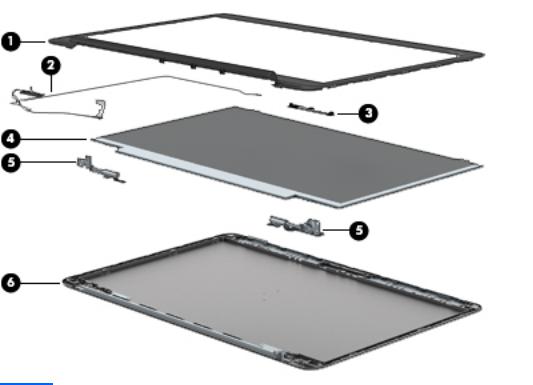
Display assembly subcomponents
Item |
Component |
Spare part number |
|
|
|
(1) |
Display bezel: |
|
|
|
|
|
For use on models with a webcam |
739568-001 |
|
|
|
|
For use on models without a webcam |
748015-001 |
|
|
|
(2) |
Display cable |
739573-001 |
|
|
|
(3) |
Webcam/microphone module |
739570-001 |
|
|
|
|
Microphone module |
739571-001 |
|
|
|
(4) |
35.6-cm (14.0-in), LED, AntiGlare display panel: |
|
|
|
|
|
SVA HD+ |
739581-001 |
|
|
|
|
UWVA |
739582-001 |
|
|
|
(5) |
Display Hinge Kit (includes left and right display hinges) |
739572-001 |
|
|
|
(6) |
Display enclosure (includes wireless antenna) |
739569-001 |
|
|
|
Display assembly subcomponents 19
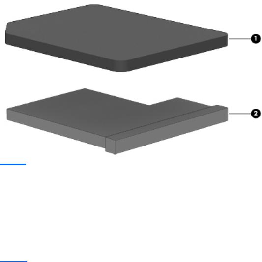
Plastics Kit
Item |
Component |
Spare part number |
|
|
|
|
Plastics Kit |
739575-001 |
|
|
|
(1) |
SIM card slot cover (for WWAN SKU) |
|
|
|
|
(2) |
SIM card insert (for non-WWAN SKU – customer non-removable) |
|
|
|
|
|
Rubber antenna cover (not illustrated) |
|
|
|
|
Mass storage devices
Item |
Description |
Spare part number |
|
|
|
(1) |
Solid-State Drive (SATA III) |
|
|
|
|
|
256-GB |
746906-001 |
|
|
|
|
180-GB |
746908-001 |
|
|
|
|
128-GB |
746907-001 |
|
|
|
20 Chapter 3 Illustrated parts catalog

Miscellaneous parts
Component |
Spare part number |
|
|
AC adapter: |
|
|
|
45-W HP Smart AC adapter (non-PFC) |
721092-001 |
|
|
65-W HP Smart AC adapter |
714657-001 |
|
|
65-W HP Smart AC travel adapter |
693716-001 |
|
|
Mouse: |
|
|
|
HP USB optical travel mouse |
434594-001 |
|
|
HP USB Laser |
674318-001 |
|
|
HP Comfort Grip Wireless Mouse |
691922-001 |
|
|
Power cord (3-pin, black, 1.83-m): |
|
|
|
For use in Argentina |
490371-D01 |
|
|
For use in Australia |
490371-011 |
|
|
For use in Brazil |
490371-202 |
|
|
For use in the Denmark |
490371-081 |
|
|
For use in Europe |
490371-021 |
|
|
For use in India |
490371-D61 |
|
|
For use in Israel |
490371-BB1 |
|
|
For use in Italy |
490371-061 |
|
|
For use in Japan |
490371-291 |
|
|
For use in North America |
490371-001 |
|
|
For use in the People's Republic of China |
490371-AA1 |
|
|
For use in South Africa |
490371-AR1 |
|
|
For use in South Korea |
490371-AD1 |
|
|
For use in Switzerland |
490371-111 |
|
|
For use in Taiwan |
490371-AB1 |
|
|
For use in Thailand |
490371-201 |
|
|
For use in the United Kingdom |
490371-031 |
|
|
Screw Kit |
746909-001 |
|
|
Docking station |
732252-001 |
|
|
Cable lock docking station |
575921-001 |
|
|
Adapter, RJ-45 to VGA |
747488-001 |
|
|
Lock, combination |
591699-001 |
|
|
Miscellaneous parts 21

Component |
Spare part number |
|
|
HP Business Slim Top Load Case |
718549-001 |
|
|
HP Business Backpack |
718548-001 |
|
|
Sequential part number listing
CSR flag designations:
A = Mandatory
B = Optional
C = Service technician recommended
N = Non-user replaceable
Spare part |
CSR |
Description |
number |
flag |
|
|
|
|
434594-001 |
A |
HP USB optical travel mouse |
|
|
|
490371-001 |
A |
Power cord for use in North America (3-pin, black, 1.83-m) |
|
|
|
490371-011 |
A |
Power cord for use in Australia (3-pin, black, 1.83-m) |
|
|
|
490371-021 |
A |
Power cord for use in Europe (3-pin, black, 1.83-m) |
|
|
|
490371-031 |
A |
Power cord for use in the United Kingdom (3-pin, black, 1.83-m) |
|
|
|
490371-061 |
A |
Power cord for use in the Italy (3-pin, black, 1.83-m) |
|
|
|
490371-081 |
A |
Power cord for use in Denmark (3-pin, black, 1.83-m) |
|
|
|
490371-111 |
A |
Power cord for use in Switzerland (3-pin, black, 1.83-m) |
|
|
|
490371-201 |
A |
Power cord for use in Thailand (3-pin, black, 1.83-m) |
|
|
|
490371-202 |
A |
Power cord for use in Brazil (3-pin, black, 1.83-m) |
|
|
|
490371-291 |
A |
Power cord for use in Japan (3-pin, black, 1.83-m) |
|
|
|
490371-AA1 |
A |
Power cord for use in the People's Republic of China (3-pin, black, 1.83-m) |
|
|
|
490371-AB1 |
A |
Power cord for use in Taiwan (3-pin, black, 1.83-m) |
|
|
|
490371-AD1 |
A |
Power cord for use in South Korea (3-pin, black, 1.83-m) |
|
|
|
490371-AR1 |
A |
Power cord for use in South Africa (3-pin, black, 1.83-m) |
|
|
|
490371-BB1 |
A |
Power cord for use in Israel (3-pin, black, 1.83-m) |
|
|
|
490371-D01 |
A |
Power cord for use in Argentina (3-pin, black, 1.83-m) |
|
|
|
490371-D61 |
A |
Power cord for use in India (3-pin, black, 1.83-m) |
|
|
|
575921-001 |
A |
Cable lock docking station |
|
|
|
591699-001 |
A |
Lock, combination |
|
|
|
674318-001 |
A |
HP USB Laser |
|
|
|
691922-001 |
A |
HP Comfort Grip Wireless Mouse |
|
|
|
22 Chapter 3 Illustrated parts catalog
 Loading...