


System
Installation
Guide
2-wire Prestige® IAQ and RF EIM
With wireless accessories
Control for up to 4 Heat/2 Cool heat pump systems or up to 3 Heat/2 Cool conventional systems.
Installation guide for:
• |
THX9000 Prestige IAQ thermostat |
• |
Portable |
Comfort Control |
• |
Equipment Interface Module |
• |
Wireless |
Outdoor Air Sensor |
DISCONNECT POWER BEFORE BEGINNING INSTALLATION. Can cause electrical shock or equipment damage.
MERCURY NOTICE: If this product is replacing a control that contains mercury in a sealed tube, do not place the old control in the trash. Contact your local waste management authority for instructions regarding recycling and proper disposal.
Must be installed by a trained, experienced technician. Read these instructions carefully. Failure to follow these instructions can damage the product or cause a hazardous condition.
Need Help?
For assistance with this product please visit http://customer.honeywell.com or call Honeywell Customer Care toll-free at 1-800-468-1502
® U.S. Registered Trademark. |
|
Copyright © 2011 Honeywell International Inc. |
69-2445EFS-03 |
All rights reserved. |

2-wire Prestige® IAQ and RF EIM
1Mount and wire thermostat
Pull wiring through hole in wall plate and install as shown below. Strip 1/4" insulation and connect wires to screw terminals as shown.
Wall anchor
Drywall: 3/16" hole |
Mounting |
|
Plaster: 7/32" hole |
||
screw |
||
|
MCR29241
MCR32386
MCR32387 |
Connect the two wires from the thermostat to the Equipment Interface Module R and C terminals or to a separate 24 volt transformer (not provided).
Wiring must comply with local electrical codes.
2Mount and wire Equipment Interface Module
Use screws & anchors (not included) as appropriate for mounting surface. Mount Equipment Interface Module on wall near HVAC equipment, or on the equipment itself.
Do not install inside HVAC equipment.
Strip 1/4” insulation, then insert wires as shown.
R
C
WB
O/
 W2AUX1
W3AUX2
Y
Y2
G
L
MCR32389
MCR32388
69-2445EFS—03 |
2 |
|
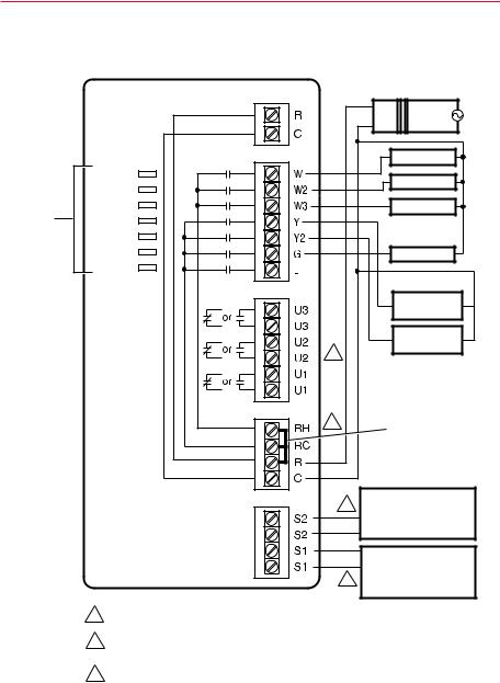
2-wire Prestige® IAQ and RF EIM
Wiring guide
Typical hookup of conventional system with up to three-stage heat and two-stage cool with single transformer.
STATUS
LEDS
|
|
FURNACE |
|
TO THERMOSTAT |
R |
TRANSFORMER |
|
|
24 |
120 |
|
|
C |
VAC |
VAC |
POWER |
CONV |
W |
STAGE 1 HEAT |
|
|
||
|
W2 |
STAGE 2 HEAT |
|
HEAT |
|
||
|
W3 |
|
|
COOL |
|
STAGE 3 HEAT |
|
FAN |
|
|
|
U1 |
|
G |
|
U2 |
|
FAN |
|
|
|
||
U3 |
|
|
|
|
|
Y |
COMPRESSOR |
|
|
|
(STAGE 1) |
|
|
Y2 |
COMPRESSOR |
|
|
1 |
(STAGE 2) |
|
|
|
3 JUMPERS
RETURN AIR SENSOR 2 DISHARGE AIR SENSOR
INDOOR SENSOR
OUTDOOR SENSOR
SENSORS
RETURN AIR SENSOR
DISHARGE AIR SENSOR 2 INDOOR SENSOR
OUTDOOR SENSOR
1 SEE WIRING GUIDE—EQUIPMENT SECTION FOR IAQ EQUIPMENT WIRING.
2 WIRE A MAXIMUM OF TWO SENSORS USING THE S1, S1, S2, S2 TERMINALS.
3 REMOVE JUMPER(S) FOR SEPARATE TRANSFORMERS.
M32390
3 |
69-2445EFS—03 |
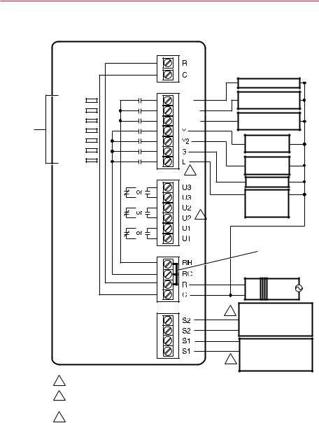
2-wire Prestige® IAQ and RF EIM
Wiring guide
Typical hookup of heat pump system with up to four-stage heat and two-stage cool with single transformer.
STATUS
LEDS
|
TO THERMOSTAT |
|
|
|
|
HEAT PUMP |
O/B |
CHANGEOVER VALVE |
|
|
|
|
BACKUP HEAT |
|
POWER |
O/B |
|
|
|
AUX1 |
|
STAGE 1 |
||
HEAT |
AUX1 |
|
||
|
|
|||
AUX2 |
|
BACKUP HEAT |
||
COOL |
AUX2 |
|
||
|
|
STAGE 2 |
||
FAN |
|
|
|
|
|
|
|
COMPRESSOR |
|
U1 |
|
|
Y |
|
U2 |
|
|
|
(STAGE 1) |
|
|
|
|
|
U3 |
|
Y2 |
COMPRESSOR |
|
|
3 |
|
G |
(STAGE 2) |
|
|
|
||
|
|
|
FAN RELAY |
|
|
|
|
|
|
|
L COMPRESSOR |
|
MONITOR OR |
1 |
ZONE PANEL |
|
JUMPERS
AIR HANDLER
TRANSFORMER
R |
24 |
120 |
|
C |
|||
VAC |
VAC |
|
2 |
RETURN AIR SENSOR |
|
DISHARGE AIR SENSOR |
|
|
|
|
|
|
INDOOR SENSOR |
SENSORS |
|
OUTDOOR SENSOR |
|
|
RETURN AIR SENSOR
DISHARGE AIR SENSOR 2 INDOOR SENSOR
OUTDOOR SENSOR
1 SEE WIRING GUIDE—EQUIPMENT SECTION FOR IAQ EQUIPMENT WIRING.
2 WIRE AT MAXIMUM OF TWO SENSORS USING THE S1, S1, S2, S2 TERMINALS.
3 L TERMINAL SENDS CONTINUOUS OUTPUT WHEN THERMOSTAT IS SET TO
EM. HEAT MODE.
M32391
69-2445EFS—03 |
4 |
|
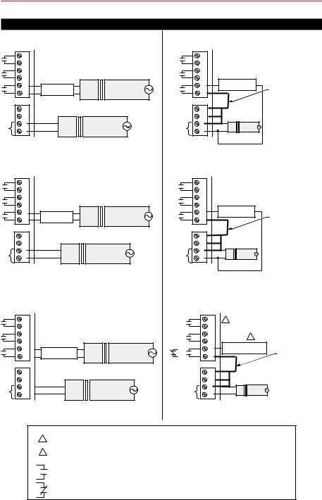
2-wire Prestige® IAQ and RF EIM
Wiring guide—equipment
Any combination of Universal relays (U1, U2, U3) can be used.
|
|
With power supply |
|
|
Without power supply |
||||
Typical hookup of powered humidifier. |
Typical hookup of non-powered humidifier. |
||||||||
|
U3 |
|
|
|
|
U3 |
|
|
|
|
U3 |
|
|
|
|
U3 |
|
|
|
|
U2 |
|
|
|
|
U2 |
|
|
|
|
U2 |
|
|
|
|
U2 |
NON-POWERED |
|
|
|
U1 |
|
|
|
|
U1 |
|
||
|
POWERED |
24 |
120 |
|
HUMIDIFIER |
FIELD INSTALLED |
|||
|
U1 |
HUMIDIFIER |
VAC |
VAC |
|
U1 |
|
|
|
|
|
|
|
JUMPER BETWEEN |
|||||
|
|
|
|
|
|
|
|
|
R AND U1 |
|
RH |
|
|
|
|
RH |
|
|
|
|
RC |
|
|
|
|
RC |
|
|
|
24 |
R |
24 |
120 |
|
24 VAC |
R |
24 |
120 |
|
VAC |
C |
VAC |
VAC |
|
C |
VAC |
VAC |
|
|
|
|
|
M32393 |
|
|
|
|||
|
|
|
|
|
|
|
|
|
|
|
|
|
|
|
|
|
|
|
M32394 |
Typical hookup of powered ventilation. |
Typical hookup of non-powered ventilation. |
||||||||
|
U3 |
|
|
|
|
U3 |
|
|
|
|
U3 |
|
|
|
|
U3 |
|
|
|
|
U2 |
|
|
|
|
U2 |
|
|
|
|
U2 |
|
|
|
|
U2 |
NON-POWERED |
|
|
|
U1 |
|
|
|
|
U1 |
|
||
|
POWERED |
24 |
120 |
|
VENTILATOR |
FIELD INSTALLED |
|||
|
U1 |
VENTILATOR |
VAC |
VAC |
|
U1 |
|
|
|
|
|
|
|
|
|
|
JUMPER BETWEEN |
||
|
|
|
|
|
|
|
|
|
R AND U1 |
|
RH |
|
|
|
|
RH |
|
|
|
|
RC |
|
|
|
|
RC |
|
|
|
24 |
R |
24 |
120 |
|
24 VAC |
R |
24 |
120 |
|
VAC |
C |
VAC |
VAC |
|
C |
VAC |
VAC |
|
|
|
|
|
|
|
|
|
|||
|
|
|
|
|
M32396 |
|
|
|
|
|
|
|
|
|
|
|
|
|
M32397 |
Typical hookup of powered dehumidifier |
Typical hookup of variable speed blower for |
||||||||
(whole house dehumidifier). |
|
dehumidification in low speed. |
|
||||||
|
U3 |
|
|
|
|
U3 |
1 |
|
|
|
|
|
|
|
|
|
|
|
|
|
U3 |
|
|
|
|
U3 |
|
|
|
|
U2 |
|
|
|
|
U2 |
|
2 |
|
|
U2 |
|
|
|
|
U2 |
|
|
|
|
|
|
|
|
DEHUMIDIFICATION |
|
|||
|
U1 |
|
|
|
|
U1 |
|
||
|
POWERED |
24 |
120 |
OR |
WITH LOW SPEED FAN |
FIELD INSTALLED |
|||
|
U1 |
DEHUMIDIFIER |
VAC |
VAC |
U1 |
|
|
||
|
|
|
|
|
|
|
JUMPER BETWEEN |
||
|
|
|
|
|
|
|
|
|
R AND U1 |
|
RH |
|
|
|
|
RH |
|
|
|
|
RC |
|
|
|
|
RC |
|
|
|
24 |
R |
24 |
|
120 |
24 VAC |
R |
24 |
120 |
|
|
VAC |
|
VAC |
|
VAC |
VAC |
|
||
VAC |
C |
|
C |
|
|||||
|
|
|
M32398 |
|
|
|
|||
|
|
|
|
|
|
|
|
|
|
|
|
|
|
|
|
|
|
|
M32392 |
KEY
1ANY COMBINATION OF UNIVERSAL RELAYS (U1, U2, U3) CAN BE USED. THEY ARE SET IN THE THERMOSTAT INSTALLER SETUP.
2WIRE THE EIM’S UNIVERSAL RELAY TO THE LOW SPEED FAN FOR DEHUMIDIFICATION CONTROL AT THE EQUIPMENT. THE EIM’S RELAY CAN BE SET TO NORMALLY OPEN OR NORMALLY CLOSED IN THE THERMOSTAT INSTALLER SEUP.
=NORMALLY OPEN, DRY CONTACTS
=NORMALLY CLOSED, DRY CONTACTS
M32409
5 |
69-2445EFS—03 |
2-wire Prestige® IAQ and RF EIM
3Link all devices to wireless network
The following instructions detail the connection process of the Prestige IAQ thermostat, Equipment Interface Module (EIM), and wireless RedLINK™ accessories.
NOTE: If the system is zoned using a TrueZONE™ panel with RedLINK™, the thermostat and accessories are connected to the Wireless Adapter. For more information, follow the connection process in the TrueZONE™ instructions.
Connection of Prestige IAQ Thermostat to the Equipment Interface Module
CONNECTE |
D |
|
|
CONNECT |
|
S2 S2 S1 S1
Next
MCR32400
Next
MCR32401
Next
MCR32402
CONNECT
LED
CONNECT
BUTTON
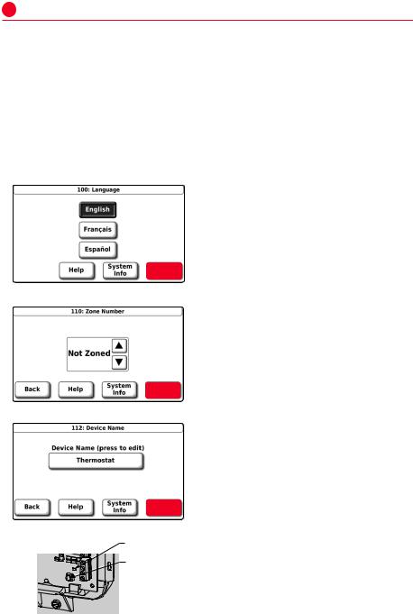
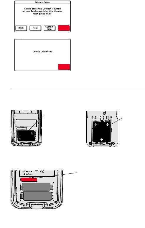
1.Connect 24 V power to the Prestige IAQ and EIM.
2.Select language and press NEXT.
3.If zoned, select zone number and press NEXT; If not zoned, select Not Zoned and press NEXT.
4.Name thermostat and press NEXT.
5.Press and release the CONNECT button at the Equipment Interface Module (EIM). The CONNECT LED on EIM will flash green.
M32399
69-2445EFS—03 |
6 |
|
2-wire Prestige® IAQ and RF EIM
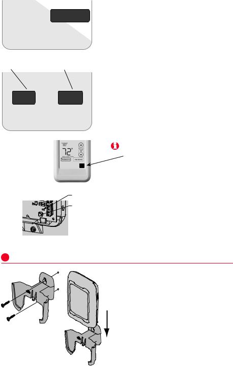
6. Press NEXT to connect the Prestige IAQ thermostat to the Equipment Interface Module (EIM).
Next
MCR32403
7. Press Done. Thermostat will advance to the Home Screen.
Done
MCR32404
Install batteries in wireless accessories
If no wireless accessories are being connected, skip to step 13.
Outdoor air sensor |
Portable Comfort Control |
(optional; steps 8–9) |
(optional; steps 10–12) |
Install 2 fresh AA |
Install 3 fresh AA |
lithium batteries |
batteries |
M28800 |
M29863 |
|
Connect Wireless Accessories: Outdoor Sensor and Portable Comfort
Control
8. Press and release the CONNECT button on the Wireless Outdoor Sensor.
9. Check thermostat to verify that the outdoor sensor is working. After about 15 seconds, the thermostat should display outdoor temperature and humidity.
MCR28847A
7 |
69-2445EFS—03 |
2-wire Prestige® IAQ and RF EIM
|
CONNECT |
WIRELESS SETUP |
|
|
M28481 |
Press to link to |
Press to save |
another thermostat |
and exit |
YES NO
CONNECT MORE?
M28482
|
|
|
M28846 |
|
|
|
CONNECT |
|
|
S2 |
LED |
|
|
CONNECT |
|
CONNECTE |
D |
S2 |
|
|
S1 |
BUTTON |
|
CONNECT |
|
||
|
S1 |
|
|
|
|
|
M32399 |
4Install outdoor sensor
M28491
M28849A
10.Press the CONNECT button on the Portable Comfort Control.
11.When the screen displays "Connected," press DONE.
12.Press NO at the next screen to save and exit. (Or press YES and repeat steps 3-5 to link another thermostat.)
The linking procedure at the Portable Comfort Control may time out if there is no keypress within 30 minutes. To begin again, press and hold the blank space (or arrow, if present) in the lower right corner of the screen until the display changes (about 3 seconds).
13.Press and release the CONNECT button at the EIM to exit (CONNECT LED on Equipment Interface Module [EIM] will be steady green). NOTE: The connection will time out automatically in 15 minutes.
1.Mount the sensor on a vertical exterior wall, at least 6 inches below any overhang. Choose a location protected from direct sunlight.
2.Place sensor securely in bracket, facing away from wall.
69-2445EFS—03 |
8 |
|
2-wire Prestige® IAQ and RF EIM
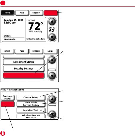
5Customize thermostat (installer options)
MENU
MCR29794
Installer Options
MCR28998
Press MENU.
Press τ to scroll down, then press INSTALLER OPTIONS. Enter security code when prompted.
Security code is the thermostat date code (printed on back of thermostat). Or press MENU > EQUIPMENT STATUS to find code.
Press CREATE SETUP to set all system settings one by one.
Press VIEW/EDIT to select a specific HELP function and make quick changes.
(See complete list of system settings on pages 10-11.)
MCR28799 Press INSTALLER TEST to run system tests. You should always test the sys-
tem after making changes to settings.
Note: Press HELP for more information on these and other options.
9 |
69-2445EFS—03 |

2-wire Prestige® IAQ and RF EIM
Installer setup tables
Setup functions |
|
|
(factory default setting listed, other options available) |
||||||
100 |
Language |
|
|
|
English |
|
|
|
|
110 |
Zone Number |
|
Not Zoned |
|
|
|
|||
112 |
Device name |
|
Thermostat |
|
|
|
|||
130 |
Date |
|
|
|
|
Month, Date, Year |
|
|
|
160 |
Schedule options |
|
Programmable |
|
|
||||
172 |
System |
selection |
|
Conventional |
|
|
|||
173 |
Heat Pump Type |
|
Air To Air |
|
|
|
|||
174 |
Stages |
|
|
|
|
1 Heat/1 Cool |
|
|
|
175 |
Series 20 Control |
|
No |
|
|
|
|||
180 |
Fan operation |
|
System (gas/oil/heat) |
||||||
190 |
Reversing valve |
|
O/B on Cool |
|
|
||||
200 |
Backup |
heat |
|
Electric |
|
|
|
||
210 |
External |
fossil fuel |
Yes |
|
|
|
|||
220 |
Compressor |
cycle |
rate(s) |
3 |
|
|
|
||
240 |
Heat stage |
cycle |
rate(s) |
5 |
|
|
|
||
300 |
Changeover |
|
|
Manual |
|
|
|
||
310 |
Deadband |
|
|
|
2° F |
|
|
|
|
320 |
Temperature display |
Fahrenheit |
|
|
|
||||
330 |
Daylight savings time |
Auto change: On |
|
|
|||||
1350 |
Configurable S1 Sensor Input |
None |
|
|
|
||||
1355 |
Configurable S2 Sensor Input |
None |
|
|
|
||||
342 |
Outdoor temperature sensor? |
No |
|
|
|
||||
346 |
Upstage timer |
|
Off |
|
|
|
|||
347 |
Droop Temperature |
2 |
|
|
|
||||
349 |
Backup Heat Control |
Comfort |
|
|
|
||||
350 |
Compressor |
lockout (balance point) |
Off |
|
|
|
|||
360 |
Auxiliary |
lockout |
|
Off |
|
|
|
||
365 |
Discharge Air Temperature Sensor |
No |
|
|
|
||||
1400 |
Configurable U1 Relay |
None |
|
|
|
||||
1405 |
Configurable U2 Relay |
None |
|
|
|
||||
1410 |
Configurable U3 Relay |
None |
|
|
|
||||
371 |
Humidification equipment |
None |
|
|
|
||||
372 |
Indoor humidity control |
Off |
|
|
|
||||
374 |
Humidifier |
fan action |
Humidify only with |
fan |
|||||
379 |
Dehumidification equipment |
None |
|
|
|
||||
1500 |
Low Speed Fan Position |
Normally Closed |
|
|
|||||
383 |
Overcooling |
limit |
|
3° F (1.5° |
C) |
|
|
||
384 |
Dehumidification fan control |
Forces fan |
on |
|
|
||||
386 |
Whole house Dehumidification Lockout |
Off |
|
|
|
||||
390 |
Dehumidification away mode |
Off |
|
|
|
||||
391 |
Away mode fan operation |
Automatic |
|
|
|
||||
392 |
Away mode low temp. setting |
76° F (24.5° C) |
|
|
|||||
393 |
Away mode high temp. setting |
85° F (29.5° C) |
|
|
|||||
394 |
Away mode dehumidification |
65% relative humidity |
|||||||
400 |
Ventilation |
Control |
|
Off |
|
|
|
||
401 |
Number of Bedrooms/Size of home |
2 (1000 sq. ft.) |
|
|
|||||
403 |
Ventilation |
levels |
|
160 cfm (50%) |
|
|
|||
405 |
Ventilation |
Fan Action |
Ventilation |
Forces |
Fan On |
||||
406 |
Ventilation |
in High Humidity |
On |
|
|
|
|||
69-2445EFS—03 |
10 |
|
|
|
|
2-wire Prestige® IAQ and RF EIM |
|
Installer setup tables |
|
|
||
|
|
|||
Setup functions |
(factory default setting listed, other options available) |
|||
431 |
Ventilation Lockout Temperatures |
None |
|
|
433 |
Ventilation Lockout High Outdoor Humidity |
Off; 75° dewpoint if On |
|
|
450 |
A-Coil Low Temperature Cutoff |
None |
|
|
500 |
Replacement reminders |
Off |
|
|
502 |
Furnace filter |
runtime counter |
Count heat and cool |
|
525 |
Installer Custom Reminders |
Add Customer Reminder |
|
|
530 |
Adaptive Intelligent Recovery |
On |
||
540 |
Number of schedule periods |
4 |
|
|
580 |
Minimum compressor off time |
5 minutes |
|
|
600 |
Temperature range stops |
90° F (32° C); 60° F (15.5° C) |
|
|
640 |
Clock format |
|
12-hour |
|
650 |
Extended fan |
on time(s) |
Off |
|
670 |
Keypad lock |
|
Unlocked |
|
680 |
Temp. control |
(heat) |
Standard |
|
690 |
Temp. control |
(cool) |
Standard |
|
695 |
Finish on High Heat Stage |
No |
|
|
696 |
Finish on High Cool Stage |
No |
|
|
700 |
Indoor display |
offsets |
No offset |
|
Customer contact information (optional, but recommended) |
||||
1100 |
Dealer name |
|
Your company name |
|
1150 |
Dealer phone number |
Your telephone contact |
|
|
1200 |
Dealer email address |
Your email address |
|
|
1250 |
Dealer website |
Your web site |
|
|
1300 |
Dealer Message |
Edit |
|
|
Note: All installer options, including Dealer name, contact information and message can be set up as a file and downloaded via the USB port on the thermostat.
Restore Factory Defaults
Under the Menu, Installer Options and Advanced Options is a button to “restore factory defaults.”
If pressed, it will reset the program schedule and most installer setup options (exceptions: 1350, 1355, 1400, 1405, 1410, 1500 and 450) and disconnect the thermostat from the Equipment Interface Module.
11 |
69-2445EFS—03 |

2-wire Prestige® IAQ and RF EIM
Accessories
Wireless Outdoor Sensor – Displays outdoor temperature and outdoor humidity on other RedLINK devices. Use for temperature lockouts in heat pump applications, condensation protection with humidification control and temperature and/or dewpoint lockouts for ventilation control.
Portable Comfort Control – Senses temperature; use to change thermostat settings.
Discharge Air Temperature Sensor – Use for desert humidification control to help prevent condensation in duct system. Also used to control coil freeze protection: it will cut off condenser and keep the blower fan running to prevent freezing the coil. If used with a Return Air Temperature Sensor the Delta T can be viewed in thermostat’s installer test.
Return Air Temperature Sensor – Use for backup control. If power is lost at thermostat, the Equipment Interface Module sets temperature to 62° F (16.7° C) in Heat and 82° F (27.8° C) in Cool until power is restored to the thermostat. If used with a Discharge Air Temperature Sensor the Delta T can be viewed in thermostat’s installer test.
Wired Indoor Temperature Sensor – Use to sense and control temperature at remote location(s); can be averaged between the thermostat and sensor location(s). See sensor instructions for installation details.
Wired Outdoor Temperature Sensor – Sends outdoor temperature for display on thermostat. Use for temperature lockouts in heat pump applications, condensation protection with humidification control and temperature lockouts for ventilation systems.
69-2445EFS—03 |
12 |
|
2-wire Prestige® IAQ and RF EIM
Replacing system components
Equipment Interface Module
After installing a new Equipment Interface Module, you must re-link all devices to the new EIM, as described below:
1.Install and wire new Equipment Interface Module.
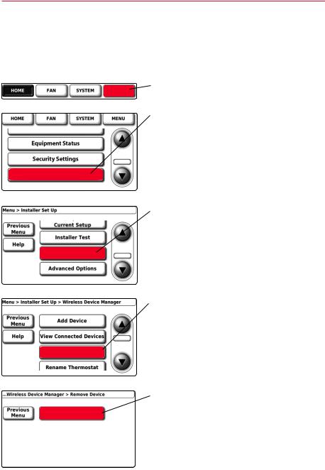
2.Disconnect thermostat from the old Equipment Interface Module.
Press MENU.
MENU
MCR28801
Installer Options
Press τ to scroll down, then press INSTALLER OPTIONS. Enter security code when prompted.
Security code is the thermostat date code (printed on back of wallplate). Or press MENU > EQUIPMENT STATUS to find code.
MCR28998
Press τ to scroll down, then press
WIRELESS DEVICE MANAGER.
Wireless Device
Manager
MCR28802
Press REMOVE DEVICE.
Remove Device
MCR32405
Press REMOVE THIS THERMOSTAT.
Remove This
Thermostat
MCR32406
13 |
69-2445EFS—03 |

2-wire Prestige® IAQ and RF EIM
Replacing system components
Equipment Interface Module (Continued)
Press YES.
Yes
MCR32407 |
M32408 |
3.Link thermostat to the new Equipment Interface Module (see pages 6–7)
Thermostat
After installing a new thermostat, you must link the new thermostat to the Equipment Interface Module, as described below.
1.Install and wire new thermostat (see pages 3-7).
2.Link thermostat to Equipment Interface Module (see pages 6–7).
Portable Comfort Control
1.Press and hold the blank space (or arrow if present) in the lower right corner of the screen until the display changes (see page 8).
2.Press REMOVE, then yes to disconnect from old Equipment Interface Module.
3.Follow the procedure on pages 7–8 to link to new Equipment Interface Module.
Outdoor air sensor
1.Press the connect button to link to the new Equipment Interface Module (see page 7).
How to disconnect all devices from the wireless network at the same time
CONNECTE |
D |
S2 |
|
S2 |
|
CONNECT |
|
S1 |
|
S1 |
M28846
CONNECT
LED
CONNECT BUTTON
M32399
Press and hold the Connect button at the Equipment Interface Module until the LED flashes amber (about 10 seconds).
NOTE: To get the Portable Comfort Control back to the connect screen, follow the instructions below.
Portable Comfort Control
Press and hold the blank space (or arrow, if present) in the lower right corner of the screen until the display changes (about 3 seconds).
69-2445EFS—03 |
14 |
|

2-wire Prestige® IAQ and RF EIM
Specifications & replacement parts
Operating Ambient Temperature
Thermostat: 32 to 120° F (0 to 48.9° C)
Portable Comfort Control: 32 to 120° F (0 to 48.9° C)
Wireless Outdoor Air Sensor: -40 to 140° F (-40 to 60° C)
Equipment Interface Module: -40 to 165° F (-40 to 73.9° C)
Return Air Sensor: 0 to 200° F (-17.8 to 93.3° C)
Discharge Air Sensor: 0 to 200° F (-17.8 to 93.3° C)
Operating Relative Humidity
Thermostat: 5% to 90% (non-condensing)
Portable Comfort Control: 5% to 90% (non-condensing)
Wireless Outdoor Air Sensor: 0% to 100% (condensing)
Equipment Interface Module: 5% to 95% (non-condensing)
Physical Dimensions (height, width, depth)
Thermostat: 3-9/16 x 5-13/16 x 1-1/2 inches (91 x 147 x 38 mm)
Wireless Outdoor Air Sensor: 5 x 3-1/2 x 1-11/16 inches (127 x 89 x 43 mm) Equipment Interface Module: 9-5/16 x 4-13/16 x 1-19/32 inches (91 x 147 x 38 mm)
Electrical Ratings
Terminal |
Voltage (50/60 Hz) |
Max. Current Rating |
|||
W - O/B |
18 |
to 30 VAC |
1.00A |
||
Y (cooling) |
18 |
to 30 |
VAC |
1.00A |
|
G (fan) |
18 |
to 30 VAC |
0.60A |
||
W2 - Aux 1 (heating) |
18 |
to 30 VAC |
0.60A |
||
Y2 |
(cooling) |
18 |
to 30 |
VAC |
0.60A |
W3 - Aux 2 |
18 |
to 30 |
VAC |
1.00A |
|
L (Output) |
18 |
to 30 |
VAC |
0.60A |
|
U1 |
|
30 |
VAC max. |
0.50A |
|
U1 |
|
30 |
VAC max. |
0.50A |
|
U2 |
|
30 |
VAC max. |
0.50A |
|
U2 |
|
30 |
VAC max. |
0.50A |
|
U3 |
|
30 |
VAC max. |
0.50A |
|
U3 |
|
30 |
VAC max. |
0.50A |
|
S1 |
|
30 |
VAC max. |
0.50A |
|
S1 |
|
30 |
VAC max. |
0.50A |
|
S2 |
|
30 |
VAC max. |
0.50A |
|
S2 |
|
30 |
VAC max. |
0.50A |
|
Accessories & Replacement Parts
Item |
Part Number |
Portable Comfort Control |
REM5000R1001 |
Wireless Outdoor Air Sensor |
C7089R1013 |
Cover Plate (covers marks left by old thermostats) |
50028399-001 |
Wired Indoor Sensor |
C7089U1005 |
Discharge Air Sensor |
C7735A1000 |
Return Air Sensor |
C7735A1000 |
Wired Outdoor Temperature Sensor |
C7089U1006 |
15 |
69-2445EFS—03 |
 Loading...