


MCR 200 - SERVICE INSTRUCTIONS
CONTENTS |
|
HEATING CONTROL |
|
HEAT CONSUMERS........................................................................................................................................................... |
3 |
Time program ........................................................................................................... |
3 |
Outside temperature controlled cut-off ..................................................................... |
3 |
Room temperature controlled cut-off ........................................................................ |
4 |
Optimization.............................................................................................................. |
4 |
HEATING CIRCUIT CONTROL........................................................................................................................................... |
5 |
Outside temperature controlled flow temperature control......................................... |
5 |
Heating characteristic .......................................................................................... |
5 |
Automatic adaptation of the heating characteristic .............................................. |
7 |
Room temperature control...................................................................................... |
13 |
Limitation of the heating up speed ..................................................................... |
14 |
Maximum limitation of the room temperature..................................................... |
14 |
Minimum limitation of the room temperature...................................................... |
14 |
Overtime compensation with TF 26 ................................................................... |
14 |
Overtime compensation via room sensor input.................................................. |
15 |
Statistics ................................................................................................................. |
15 |
Determining the number of degree days............................................................ |
15 |
Counter for operating hours ............................................................................... |
15 |
External temperature demand ................................................................................ |
16 |
Overlapping mixing circuit functions, sensors, device connections ................... |
17 |
Passing on the outside temperature sensor value through the C bus ............... |
17 |
Signal: Hot water priority switching and system overheating, |
|
corrosion protection .............................................................................. |
17 |
Janitor function, heating limits ................................................................................ |
18 |
Flow temperature control........................................................................................ |
19 |
Setpoint ramp (flow temperature)....................................................................... |
19 |
Limitations, special functions.................................................................................. |
20 |
Limitation of the heating flow temperature - minimum and maximum................ |
20 |
Pump logic ......................................................................................................... |
20 |
Boiler excess...................................................................................................... |
20 |
Screed drying heating function according to DIN 4725/T4................................. |
20 |
Protective functions ................................................................................................ |
21 |
Frost protection .................................................................................................. |
21 |
Pump actuation .................................................................................................. |
21 |
Mixing valve and pump forced operation ........................................................... |
21 |
Domestic hot water control ..................................................................................... |
22 |
Standard control................................................................................................. |
22 |
Domestic hot water priority settings ................................................................... |
22 |
Domestic hot water charging pump.................................................................... |
22 |
Pump forced operation....................................................................................... |
23 |
BOILER / BOILER SEQUENCE CONTROL ..................................................................................................................... |
24 |
Setpoint setting....................................................................................................... |
24 |
1. Flow temperature demand from other MCR 200 controllers |
|
through the LC or C bus................................................................................. |
24 |
2. Flow temperature demand through analog voltage signal |
|
(only for MCR 200-71).................................................................................... |
24 |
3. Flow temperature demand by floating normally open contact |
|
(only for MCR 200-71).................................................................................... |
25 |
4. Minimum demand (only MCR 200-71) ........................................................... |
27 |
5. Flow demand by EXCEL 5000 system.......................................................... |
27 |
6. Flow demand by an internal heating circuit program HKZ ............................ |
27 |
Setpoint formation .................................................................................................. |
28 |
Excess................................................................................................................ |
28 |
Limitations.......................................................................................................... |
28 |
Minimum limitation / Boiler corrosion protection ................................................ |
28 |
Maximum limitation / Boiler overheating (for single boiler)................................. |
28 |
Boiler overheating for boiler sequence (MCR 200-71 only ................................ |
28 |
Return temperature limitation control ..................................................................... |
29 |
Minimum switch-on time of the burner (Code 706 / 806) ................................... |
29 |
Minimum switch-off time of the burner (Code 707 / 807) ................................... |
29 |
(EN\2R\EN2R1120.DOC) 01.04.98 |
1 |
EN 2R-1120 |

MCR 200 - SERVICE INSTRUCTIONS
Total shutdown of the boiler (Code 703 / 802) ................................................... |
29 |
Boiler sequence exchange (only MCR 200-71).................................................. |
29 |
Leading boiler .................................................................................................... |
30 |
Parallel / sequential boiler sequence ................................................................. |
30 |
Outside temperature blockage of the 2nd boiler ................................................ |
30 |
Strategy function (only MCR 200-71) ..................................................................... |
31 |
Heating up time (Code 921)............................................................................... |
31 |
Gradient waiting time (Code 708 / 808) ............................................................. |
31 |
Overheating of strategy temperature ................................................................. |
31 |
Control range strategy (Code 914)..................................................................... |
32 |
PID method (only MCR 200-71) ............................................................................. |
34 |
Starting circuit for modulating burner (MCR 200-71/22)......................................... |
34 |
Boiler control for single-boiler systems:.................................................................. |
35 |
Boiler sensor / Sensor detection: ....................................................................... |
35 |
Outside sensor:.................................................................................................. |
35 |
Pump run-on time (only MCR 200-71) ............................................................... |
35 |
Using a heating controller as boiler return temperature controller ..................... |
35 |
Alarms / Faults........................................................................................................ |
36 |
Burner fault ........................................................................................................ |
36 |
Boiler pump fault ................................................................................................ |
36 |
Status displays in the.............................................................................................. |
36 |
operating sequence................................................................................................ |
36 |
WE (total heat generator / strategy) only for MCR 200-71................................. |
36 |
WE1 / WE2 ........................................................................................................ |
36 |
DISTRICT HEATING CONTROLLER................................................................................................................................ |
37 |
Return temperature limitation ................................................................................. |
37 |
Return interval flushing........................................................................................... |
38 |
100 % function........................................................................................................ |
38 |
Control parameters for district heating valve .......................................................... |
39 |
Unmixed domestic hot water storage tank control.................................................. |
39 |
Manuelle Warmwasserladung............................................................................ |
39 |
Switch on conditions for the secondary loading pump....................................... |
39 |
Sollwertbegrenzung Warmwasserladung........................................................... |
39 |
Protection against calcification........................................................................... |
40 |
Boiler or flow temperature requirement of the hot water control ....................... |
40 |
Minimum valve lift for incidental amount suppression........................................ |
40 |
Heat meter connection ........................................................................................... |
41 |
Electrical connection .......................................................................................... |
41 |
Computing the heat power and the volume flow.................................................... |
42 |
AIR CONDITION CONTROL........................................................................................................................................................ |
43 |
HARDWARE ................................................................................................................................................................................ |
44 |
COMMUNICATION |
|
CONTROLLER TO CONTROLLER SIGNALS .................................................................................................................. |
45 |
MCR 200 Fax – Controller ...................................................................................... |
46 |
MCR 200 Voice – Controller ................................................................................... |
47 |
MCR 200 – EXCEL................................................................................................. |
47 |
C-Bus ................................................................................................................. |
47 |
Outside temperature indications............................................................................. |
48 |
INSTALLATION CHECKLIST ...................................................................................................................................................... |
49 |
CODE TABLES ............................................................................................................................................................................ |
50 |
EN 2R-1120 |
2 |
01.04.98 (EN\2R\EN2R1120.DOC) |

MCR 200 - SERVICE INSTRUCTIONS
HEATING CONTROL
Heat consumers
Time program
Different room temperatures can be selected in the time program of the MCR 200. According to setting, one refers to heating operation (normal operation), temperature reduction (reduced operation) or cut-off. MCR 200 has time programs for every mixing circuit for the switching points of which an individual setpoint can be set.
Example: A room temperature of 21 °C should be guaranteed in the senior citizens gymnastics hour in a multipurpose building (heating operation). In school sports events on the other hand, a setpoint of 18 °C can be set. The heating is then operated reduced.
The corresponding time program looks like the following:
09:00 Setpoint 21 °C
10:00 Setpoint 18 °C
The heating can also be switched off with the time program for optimizing the energy consumption. The heating circuit pump is switched off and the mixing valve closed for this purpose. If the heating is switched off, only frost protection functions which prevent the heating system freezing are active.
So that the heating is switched off, the optimization for heating up must be switched on in the time program.
Example: after the school sports, the heating is switched off completely.
09:00 |
Setpoint 21 |
°C |
Opt: yes |
optimized heating up, |
|
|
|
|
so that 21°C are reached |
|
|
|
|
by 9.00 am |
10:00 |
Setpoint 18 |
°C |
Opt: no |
only reducing the room |
|
|
|
|
setpoint to 18 °C |
12:00 |
Setpoint 15 |
°C |
Opt: yes |
early cut-off |
According to the temperature sensors present, the controller switches off outside temperature controlled or room temperature controlled.
So that the residual heat of the building is utilized optimally, the heating switches on or off already before the switching points. Naturally the time period for optimization with room temperature sensor is calculated depending upon the momentary temperatures. In the case of optimization without room temperature sensor, the time period is calculated only depending upon the outside temperature.
Outside temperature controlled cut-off
The outside temperature controlled cut-off function is activated if no room temperature sensor is present and "Opt: yes" is selected.
If the outside temperature drops below the frost protection limit of 2 °C, for instance, the heating circuit pump is switched on. The flow temperature is controlled so that the heating system does not freeze.
(EN\2R\EN2R1120.DOC) 01.04.98 |
3 |
EN 2R-1120 |

MCR 200 - SERVICE INSTRUCTIONS
Room temperature controlled cut-off
The room temperature controlled cut-off function is activated automatically if a room temperature sensor is connected to the corresponding heating circuit and
"Opt:yes" is selected. (The Code No. 133, 233, 333, 433 must also stand at 1).
If the time program switches the heating off, the control is switched over to room temperature control. In this way the heating is switched off in the night until the temperature has dropped to the corresponding setpoint. To avoid the room cooling down too much, the pump is switched on and the mixing valve opened.
If the outside temperature drops below the frost protection limit of 0 °C, for instance, the heating circuit pump is switched on continuously.
Optimization
The switching times of the time program can be shifted corresponding to the temperatures to opimize the energy consumption. Since there can be heating circuits without room temperature sensors, a distinction is made between optimization with room temperature sensor and optimization without room temperature sensor.
CODE - 133 - 233 - 333 - 433 |
||
Room temperature sensor for optimization |
||
= 1 |
→ |
Optimization with room temperature sensor |
= 0 |
→ |
Optimization without room temperature sensor |
|
|
|
EN 2R-1120 |
4 |
01.04.98 (EN\2R\EN2R1120.DOC) |

MCR 200 - SERVICE INSTRUCTIONS
Heating circuit control
The heating circuits serve for temperature control with a mixing valve. The following controls can be implemented by setting code values:
CODE 117 - 217 - 317 - 417
Type of control |
|
|
= 2 |
→ |
Outside temperature controlled flow temperature control |
= 1 |
→ |
Room temperature control |
= 3 |
→ |
Constant flow temperature control, |
|
|
internal 0...10 V signal |
= 4 |
→ |
External requirement with switching contact, outside |
|
|
temperature controlled |
= 5 |
→ |
External requirement with switching contact, independent of |
outside temperature
Outside temperature controlled flow temperature control
The MCR 200 control units are set in the factory as outside temperature controlled flow temperature control, i.e. a certain flow temperature is assigned to each outside temperature by the heating characteristic. If a room temperature sensor is connected in addition, then the controller can automatically set (adapt) its heating characteristic. The room temperature can be set for different requirements with a time program. The night cut-off and optimizing the switching times enables energy to be utilized optimally.
In addition, the maximum room temperature can be limited by connecting a room temperature sensor. This adjustable limiting function ensures that heating energy is not consumed unnecessarily.
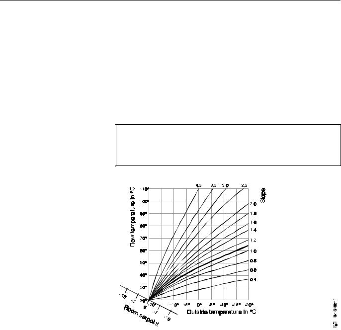
Heating characteristic
The outside temperature controlled flow temperature controller requires a heating characteristic according to which it can provide the correct flow temperature for the mixing circuit concerned corresponding to the outside temperature.
The heating characteristic shows the relationship between the outside temperature and the associated flow temperature.
Fig.
Heating characteristic
Basic setting for heating circuit 1
Slope 1.6, curvature 1.33
(EN\2R\EN2R1120.DOC) 01.04.98 |
5 |
EN 2R-1120 |
MCR 200 - SERVICE INSTRUCTIONS
Basic setting
After start-up, the controller works initially with a basic setting made in the factory.
The slope of this characteristics is 1.6.
The curvature of this characteristic is 1.33 and applies for DIN radiators.
The selected room temperature of this heating characteristic is 20 °C
Setting recommendation
Both the slope and the curvature can be changed in the settings menu with the index key.
The room temperature can be changed in the time program or through the external remote control.
IMPORTANT NOTE:
The basic factory setting must be changed for a part of the system which is designed as floor heating. Otherwise damage due to too high flow temperatures could arise at low outside temperatures. We therefore basically recommend a limiting thermostat which switches off the mixing valve at too high flow temperatures.
Fig. |
|
Heating characteristic |
|
Curvature |
|
for floor heating |
approx. 1.1 |
DIN radiators or plate heaters |
approx. 1.3 |
Convectors |
approx. 1.5 |
Setting recommendation for floor heating:
∙ |
Slope of the heating characteristic: |
0.8 |
∙ |
Curvature of the heating characteristic: |
1.1 |
∙Maximum limitation of the flow temperature to design value, e.g. 50 °C.
This maximum limitation does not replace any safety measures such as the safety temperature limiter required for floor heating systems
(CODE No. 102, 202, 302 and 402).
EN 2R-1120 |
6 |
01.04.98 (EN\2R\EN2R1120.DOC) |

MCR 200 - SERVICE INSTRUCTIONS
The basic setting does not have to be changed for all other types of system in which higher flow temperatures are permitted. The controller corrects the heating characteristic by the adaptation automatically.
The curvature depends exclusively upon the type of heating system or upon the type of the radiators. The larger the numerical value, the more is the heating characteristic curved.
CODE 102 - 202 - 302 - 402
Maximum limitation [°C]
Automatic adaptation of the heating characteristic
The ability of the controller to adapt the default heating characteristic (heating curve) step by step automatically to the building heating characteristic is called adaptation. The mean values of the room temperature, of the outside and flow temperature are the working variables for the adaptation.
Adaptation with room temperature sensor
If a room temperature sensor is connected, then the adaptation for the control loop concerned is automatic. The temperature is measured during the entire daily operation.
The correction of the heating characteristic by adaptation is not made until the 3rd day. If the basic setting (1.6) is too high, it can be that too high flow temperatures occur in the first days. If the adaptation has already been running over a longer period, a well adapted heating characteristic has become established.
No thermostatic valve may be effective in the room (test room) in which the room sensor is installed. The radiator in the test room must always be fully opened, otherwise the automatic adaptation cannot work or leads to faulty interpretations. Open fire places, tile stoves and too frequent airing in the initial phase after starting the application can lead to faulty interpretations.
Prerequisites for each mixing circuit are:
∙A room sensor must be connected.
∙The room temperature setpoint must be higher than 18 °C and the heating circuit pump running time must be at least 6 hours per day.
∙The outside temperature averaged during the heating circuit pump running time must be below 15 °C.
∙The adaptation must be allowed (CODE No. 131, 231, 331, 431).
If these conditions are fulfilled, then automatic adaptation takes place.
Adaptation must have taken place at least three times before the basic setting of the heating characteristic can be changed.
The controller corrects the heating characteristic around midnight. In this case the corrections for each following adaptation day are always weaker.
Note |
The curvature can be changed only manually through the operating |
|
unit and is preallocated with 1.33 for all heating circuits |
|
(DIN radiators). |
The curvature depends exclusively upon the type of the heating system or upon the type of the radiators. The larger the numerical value, the more is the heating characteristic curved.
CODE 131 - 231 - 331 - 431 |
||
Allow / prevent adaptation |
||
= 0 |
→ |
Adaptation not allowed |
= 1 |
→ |
Adaptation allowed |
= 2 |
→ |
New start of the adaptation |
|
|
|
(EN\2R\EN2R1120.DOC) 01.04.98 |
7 |
EN 2R-1120 |
MCR 200 - SERVICE INSTRUCTIONS
Optimization without room sensor (floor heating, ...)
(Code 133 = 0)
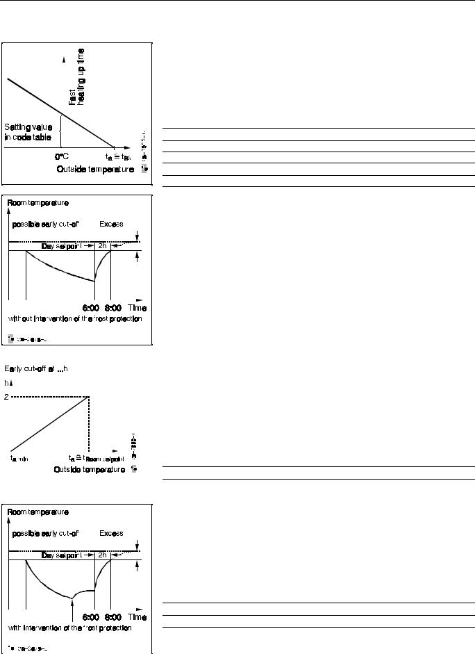
Heating up
The controller works in the heating up process with a fixed adjustable room temperature excess (CODE No. 136, 236, 336, 436) and varies the heating up time with the outside temperature.
The heating time at 0 °C outside temperature (Fig. on the left) can be set in the Code Table (CODE No. 137, 237, 337, 437).
CODE 136 - 236 - 336 - 436
Room temperature excess [°C]
CODE 137 - 237 - 337 - 437
Heating up time at 0 °C [min]
The flow temperature for heating up is established according to the heating characteristic plus the set room temperature excess. The settings of the time constants and dead times are not relevant for this heating up optimization. If the target time is reached (as in the example diagram 8.00 am), then the controller switches back to normal control.
This type of optimization is recommended for floor heating systems, for instance. Large dead times, as are customary in floor heating systems, have no influence on the switch-on time in this method.
Cut-off
On cut-off, the outside temperature influences the cut-off time. Thus all relationships are determined by the diagram without it being possible to take account of the room temperature. The maximum early cut-off is 2 hours. The switching point must always be set at the latest possible cut-off.
The limiting value of the outside temperature, ta min can be used for the early cut-off in the Code Table (CODE No. 138, 238, 338, 438).
This means that the controller cuts off the heating earlier between this limiting value and the current room setpoint.
CODE 138 - 238 - 338 - 438
Minimum outside temperature for early cut-off [°C]
If the outside temperature is below the set limiting value, there is no early cut-off.
The heating is switched off during the set back period (pump off, mixing valve closed). A minimum limitation which may be set (CODE No. 101, 201, 301, 401) has higher priority on the other hand and remains valid during the cut-off.
The controller switches the pumps on and the control circuit works with the current night setpoint from the time program (supporting mode) only if the temperature drops below the frost protection limit (CODE No. 109, 209, 309, 409).
CODE 109 - 209 - 309 - 409
Frost protection limit [°C]
|
|
|
|
|
|
|
|
|
|
EN 2R-1120 |
8 |
01.04.98 (EN\2R\EN2R1120.DOC) |
||

MCR 200 - SERVICE INSTRUCTIONS
Optimization with room sensor
(Code 133 = 1)
It is possible to record the residual heat in a building only if a room sensor is installed.
Thus the controller can determine the heating up time with the additional information of dead time and time constant and the values of outside temperature, maximum flow temperature and room temperature. There are two possibilities of heating up the system optimally in heating up optimization with room sensor.
Temperature-variable heating up
The heating up time is constant in this case (CODE No. 134, 234, 334, 434).
The flow temperature is calculated depending upon the required energy.
CODE 134 - 234 - 334 - 434
Heating up time [min]
Time-variable heating up
If the maximum flow temperature is required for heating up, then with growing heat demand the controller can only shift the heating up time towards earlier times. This transition is influenced by a setting in the Code Table (CODE No. 134, 234, 334, 434 and 135, 235, 335, 435).
Here the minimum heating up time and the maximum flow temperature available are determined for heating up. The heating up process starts at the calculated time with the maximum flow temperature for heating up (CODE No. 135, 235, 335, 435).
CODE 134 - 234 - 334 - 434
Heating up time [min]
CODE 135 - 235 - 335 - 435
max. flow temperature for heating up [°C]
The heating system is switched off before heating up (pump off, mixing valve closed). A minimum limitation which may be set (CODE No. 101, 201, 301, 401) has on the other hand higher priority and remains valid during the cut-off. If the room temperature drops below the set night setpoint during the temperature reduction time, then the controller switches automatically over to room temperature control.
If the room temperature reaches the setpoint before the target time, then the system switches over to room control.
If the target time is reached, the controller works basically for a further 30 minutes as room temperature controller. It then switches back to outside temperature control.
CODE 101 - 201 - 301 - 401
Minimum limitation [°C]
(EN\2R\EN2R1120.DOC) 01.04.98 |
9 |
EN 2R-1120 |
MCR 200 - SERVICE INSTRUCTIONS
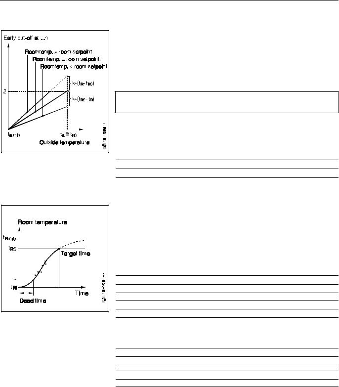
Cut-off with room sensor
In the cut-off with room sensor, the current room temperature is included in the
calculation of the early cut-off.
∙ If the room temperature tR is equal to the setpoint tRS, then the early cut-off
applies as in the case without room sensor.
∙ If the room temperature tR is greater than the setpoint tRS (solar radiation, per-
sonal heat, then the set characteristic becomes steeper, i.e. the heating switches off earlier (max. 2 hours).
NOTE: If the room temperature tR is smaller than the setpoint tRS, then the set characteristic becomes flatter. The heating remains switched on longer, as a maximum up to the programmed cut-off point.
In the code Table, the limiting value of the outer temperature ta min can be set via the early cut-off (CODE No. 138, 238, 338, 438).
This means that at this limiting value, the controller cuts off the heating earlier. If the outside temperature is below the set limiting value, then there is no early cutoff.
CODE 138 - 238 - 338 - 438
Minimum outside temperature for early cut-off [°C]
Identification of time constant and dead time
The program identifies the necessary time constants and dead times for heating up optimization with room sensor.
Two parameter set are identified:
∙ Dead time 1 (CODE No. 140, 240, 340, 440) and time constant 1
(CODE No. 141, 241, 341, 441) of the room model for short temperature reductions
(shorter than 24 hours).
CODE 140 - 240 - 340 - 440
Dead time for short temperature reduction [min]
CODE 141 - 241 - 341 - 441
Time constant for short temperature reduction [min]
∙Dead time 2 (CODE No. 142, 242, 342, 442) and time constant 2 (CODE No. 143, 243, 343, 443) for temperature reductions lasting longer than 24 hours.
CODE 142 - 242 - 342 - 442
Dead time for long temperature reduction [min]
CODE 143 - 243 - 343 - 443
Time constant for long temperature reduction [min]
Dead times and time constants are determined in the heating up process. Proceeding from the basic settings, the parameters are corrected automatically in each heating up process.
After the end of the dead time, the room temperature is measured every 15 minutes and the new time constant is estimated.
The identification is completed when the room temperature controller starts. Before the newly determined parameter set is made use of, there is a plausibility check. The value present in the memory is then replaced by a mean value formed from the old and new value.
EN 2R-1120 |
10 |
01.04.98 (EN\2R\EN2R1120.DOC) |
MCR 200 - SERVICE INSTRUCTIONS
Depending upon the cut-off time of the heating system, the controller uses in each case the first or second parameter set for calculating the heating up time.
The parameters can be identified only if the following conditions are fulfilled:
∙ The identification is not disabled (CODE No. 132, 232, 332, 432).
CODE 132 - 232 - 332 - 432
Identification |
|
|
= 0 |
→ |
disabled |
= 1 |
→ |
enabled |
= 2 |
→ |
New start |
∙A room sensor is connected.
∙The temperature difference between room temperature on switching on the heating and room temperature setpoint at the target time is greater than 2 K.
∙The outside temperature is less than 10 °C.
The basic setting values for the two parameter sets (dead time, time constant) represent the starting point of the identification.
Solar compensation
The solar radiation influences the value of the damped outside temperature through the SAF20. A radiation power of 500 W/m2 has around the same effects as an outside temperature which is 20 K warmer.
The influence of the compensation can be adjusted between 0 and -1 for all heating circuits (CODE No. 116, 216, 316, 416).
CODE 116 - 216 - 316 - 416
Solar compensation
= 0 → off = -1 → on
|
|
|
|
|
|
|
|
|
|
|
|
|
|
|
|
|
|
|
|
|
|
|
|
|
|
|
|
|
|
|
|
|
|
|
|
|
|
|
|
|
|
|
|
|
|
|
|
|
|
|
|
|
|
|
|
|
|
|
|
|
|
|
|
|
|
|
|
|
|
|
|
|
|
|
|
|
|
|
|
|
|
|
|
|
|
|
|
|
|
|
|
|
|
|
|
|
|
|
|
|
|
|
|
|
|
|
|
|
|
|
|
|
|
|
|
|
|
|
|
|
|
|
|
|
|
|
|
|
|
|
|
|
|
|
|
|
|
|
|
|
|
|
|
|
|
|
|
|
|
|
|
|
|
|
|
|
|
|
|
|
|
|
|
|
|
|
|
|
|
|
|
|
|
|
|
|
|
|
|
|
|
|
|
|
|
|
|
|
|
|
|
|
|
|
|
|
|
|
|
|
|
|
|
|
|
|
|
|
|
|
|
|
|
|
|
|
|
|
|
|
|
|
|
|
|
|
|
|
|
|
|
|
|
|
|
|
|
|
|
|
|
|
|
|
|
|
|
|
|
|
|
|
|
|
|
|
|
|
|
|
|
|
|
|
|
|
|
|
|
|
|
|
|
|
|
|
|
|
|
|
|
|
|
|
|
|
|
|
|
|
|
|
|
|
|
|
|
|
|
|
|
|
|
|
|
|
|
|
|
|
|
|
|
|
|
|
|
|
|
|
|
|
|
|
|
|
|
|
|
|
|
|
|
|
|
|
|
|
|
|
|
|
|
|
|
|
|
|
|
|
|
|
|
|
|
|
|
|
|
|
|
|
|
|
|
|
|
|
|
|
|
|
|
|
|
|
|
|
|
|
|
|
|
|
|
|
|
|
|
|
|
|
|
|
|
|
|
|
|
|
|
|
|
|
|
|
|
|
|
|
|
|
|
|
|
|
|
|
|
|
|
|
|
|
|
|
|
|
|
|
|
|
|
|
|
|
|
|
|
|
|
|
|
|
|
|
|
|
|
|
|
|
|
|
|
|
|
|
|
|
|
|
|
|
|
|
|
|
|
|
|
|
|
|
|
|
(EN\2R\EN2R1120.DOC) 01.04.98 |
11 |
|
|
|
|
|
|
|
|
|
|
|
|
|
|
|
|
EN 2R-1120 |
||||||||||||||||||||||||||||||||||
MCR 200 - SERVICE INSTRUCTIONS
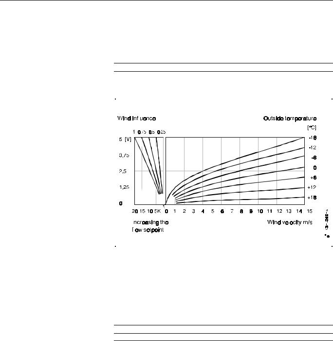
Wind compensation
The wind compensation acts exactly in the opposite way as the solar compensation. At maximum wind loading (15 m/sec.), the value of the outside temperature is reduced by max. 20 K.
The influence of the wind compensation can be set between 0 and +1 for all three heating circuits (CODE No. 116, 216, 316, 416).
CODE 116 - 216 - 316 - 416
|
Wind compensation |
|
|
|
|
|
|
|
|
|
|
|
|
|
|
|
|
|
|
|
|
|
|
|
|
|
|
|
|
|
|
|
|
|
|
|||||||||||||||||||||||||||
= 0 |
|
|
|
|
|
|
|
|
|
|
|
|
|
|
|
|
|
|
|
|
|
|
|
|
→ |
off |
||||||||||||||||||||||||||||||||||||
= +1 |
|
|
|
|
|
|
|
|
|
|
|
|
|
|
|
|
|
|
|
|
|
|
|
|
→ |
on |
||||||||||||||||||||||||||||||||||||
|
|
|
|
|
|
|
|
|
|
|
|
|
|
|
|
|
|
|
|
|
|
|
|
|
|
|
|
|
|
|
|
|
|
|
|
|
|
|
|
|
|
|
|
|
|
|
|
|
|
|
|
|
|
|
|
|
|
|
|
|
|
|
|
|
|
|
|
|
|
|
|
|
|
|
|
|
|
|
|
|
|
|
|
|
|
|
|
|
|
|
|
|
|
|
|
|
|
|
|
|
|
|
|
|
|
|
|
|
|
|
|
|
|
|
|
|
|
|
|
|
|
|
|
|
|
|
|
|
|
|
|
|
|
|
|
|
|
|
|
|
|
|
|
|
|
|
|
|
|
|
|
|
|
|
|
|
|
|
|
|
|
|
|
|
|
|
|
|
|
|
|
|
|
|
|
|
|
|
|
|
|
|
|
|
|
|
|
|
|
|
|
|
|
|
|
|
|
|
|
|
|
|
|
|
|
|
|
|
|
|
|
|
|
|
|
|
|
|
|
|
|
|
|
|
|
|
|
|
|
|
|
|
|
|
|
|
|
|
|
|
|
|
|
|
|
|
|
|
|
|
|
|
|
|
|
|
|
|
|
|
|
|
|
|
|
|
|
|
|
|
|
|
|
|
|
|
|
|
|
|
|
|
|
|
|
|
|
|
|
|
|
|
|
|
|
|
|
|
|
|
|
|
|
|
|
|
|
|
|
|
|
|
|
|
|
|
|
|
|
|
|
|
|
|
|
|
|
|
|
|
|
|
|
|
|
|
|
|
|
|
|
|
|
|
|
|
|
|
|
|
|
|
|
|
|
|
|
|
|
|
|
|
|
|
|
|
|
|
|
|
|
|
|
|
|
|
|
|
|
|
|
|
|
|
|
|
|
|
|
|
|
|
|
|
|
|
|
|
|
|
|
|
|
|
|
|
|
|
|
|
|
|
|
|
|
|
|
|
|
|
|
|
|
|
|
|
|
|
|
|
|
|
|
|
|
|
|
|
|
|
|
|
|
|
|
|
|
|
|
|
|
|
|
|
|
|
|
|
|
|
|
|
|
|
|
|
|
|
|
|
|
|
|
|
|
|
|
|
|
|
|
|
|
|
|
|
|
|
|
|
|
|
|
|
|
|
|
|
|
|
|
|
|
|
|
|
|
|
|
|
|
|
|
|
|
|
|
|
|
|
|
|
|
|
|
|
|
|
|
|
|
|
|
|
|
|
|
|
|
|
|
|
|
|
|
|
|
|
|
|
|
|
|
|
|
|
|
|
|
|
|
|
|
|
|
|
|
|
|
|
|
|
|
|
|
|
|
|
|
|
|
|
|
|
|
|
|
|
|
|
|
|
|
|
|
|
|
|
|
|
|
|
|
|
|
|
|
|
|
|
|
|
|
|
|
|
|
|
|
|
|
|
|
|
|
|
|
|
|
|
|
|
|
|
|
|
|
|
|
|
|
|
|
|
|
|
|
|
|
|
|
|
|
|
|
|
|
|
|
|
|
|
|
|
|
|
|
|
|
|
|
|
|
|
|
|
|
|
|
|
|
|
|
|
|
|
|
|
|
|
|
|
|
|
|
|
|
|
|
|
|
|
|
|
|
|
|
|
|
|
|
|
|
|
|
|
|
|
|
|
|
|
|
|
|
|
|
|
|
|
|
|
|
|
|
|
|
|
|
|
|
|
|
|
|
|
|
|
|
|
|
|
|
|
|
|
|
|
|
|
|
|
|
|
|
|
|
|
|
|
|
|
|
|
|
|
|
|
|
|
|
|
|
|
|
|
|
|
|
|
|
|
|
|
|
|
|
|
|
|
|
|
|
|
|
|
|
|
|
|
|
|
|
|
|
|
|
|
|
|
|
|
|
|
|
|
|
|
|
|
|
|
|
|
|
|
|
|
|
|
|
|
|
|
|
|
|
|
|
|
|
|
|
|
|
|
|
|
|
|
|
|
|
|
|
|
|
|
|
|
|
|
|
|
|
|
|
|
|
|
|
|
|
|
|
|
|
|
|
|
|
|
|
|
|
|
|
|
|
|
|
|
|
|
|
|
|
|
|
|
|
|
|
|
|
|
|
|
|
|
|
|
|
|
|
|
|
|
|
|
|
|
|
|
|
|
|
|
|
|
|
|
|
|
Dynamic outside temperature adaptation
To take account of residual heat in the building, the outside temperature control does not work with the current outside temperature, but with a delayed outside temperature.
The effect of this is that the delayed outside temperature passes on fast outside temperature changes later and also weaker to the controller, just as in the case of the wind influence.
The building parameter T (CODE No. 112, 212, 312, 412) is a direct measure for the delay.
CODE 113 - 213 - 313 - 413
Building parameter T [h]
Typical values: |
|
very light construction |
approx. 0.5 h |
light construction |
approx. 2 h |
medium heavy construction approx. 5 h heavy construction approx. 10 h
EN 2R-1120 |
12 |
01.04.98 (EN\2R\EN2R1120.DOC) |
MCR 200 - SERVICE INSTRUCTIONS
Room temperature control
If wanted, the controller can also work as room temperature controller. Set the CODE No. 117, 217, 317, 417 to "1" for this purpose.
In room temperature control, the controller decides by reference to the actual room temperature and the room temperature set point the flow temperature which the mixing valve must set. If room temperature control is wanted, no thermostatic valve may be attached to the radiator in the room in which the room sensor is installed. All radiator valves must be fully opened.
The room temperature controller is designed as cascade controller, whereby the main controller is the room temperature controller and the auxiliary controller is the flow temperature controller.
The sensitivity of the room temperature controller is set with the proportional band. The proportional band changes the flow temperature setpoint immediately if the room temperature changes.
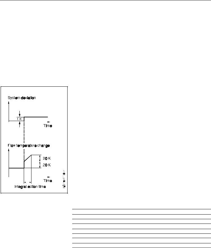
A change of the room temperature by 1 K results (at P band Xp = 5 K; CODE No. 122, 222, 322, 422) in a change of the flow setpoint by 20 K.
At Xp = 2 K, the flow setpoint changes by 50 K.
It applies that: 1 / XP x 100 K = tflow
The working point of the room temperature controller is determined by the heating characteristic (heating curve).
An outside temperature sensor is also required for the room temperature control.
The integral action time (CODE No. 123, 223, 323, 423) states the time after which, with unchanging system deviation, the controller increases the flow setpoint by the same amount as it reaches due to the P component. The control circuit works as pure P controller with integral action times < 15 s.
In most cases, the P controller is sufficient for the room temperature control, since the working point is determined by the heating characteristic and thus a low P deviation can be expected.
So that not too high setpoint temperature requirements are placed on the boiler during the morning heating up, the P controller is set as basic setting for the room control.
A response threshold (CODE No. 124, 224, 324, 424) prevents continuous intervention for small changes.
CODE 122 - 222 - 322 - 422
Proportional band of the room temperature control [K/K]
CODE 123 - 223 - 323 - 423
Integral action time [sec]
CODE 124 - 224 - 324 - 424
Response threshold [K]
(EN\2R\EN2R1120.DOC) 01.04.98 |
13 |
EN 2R-1120 |
MCR 200 - SERVICE INSTRUCTIONS
Limitation of the heating up speed
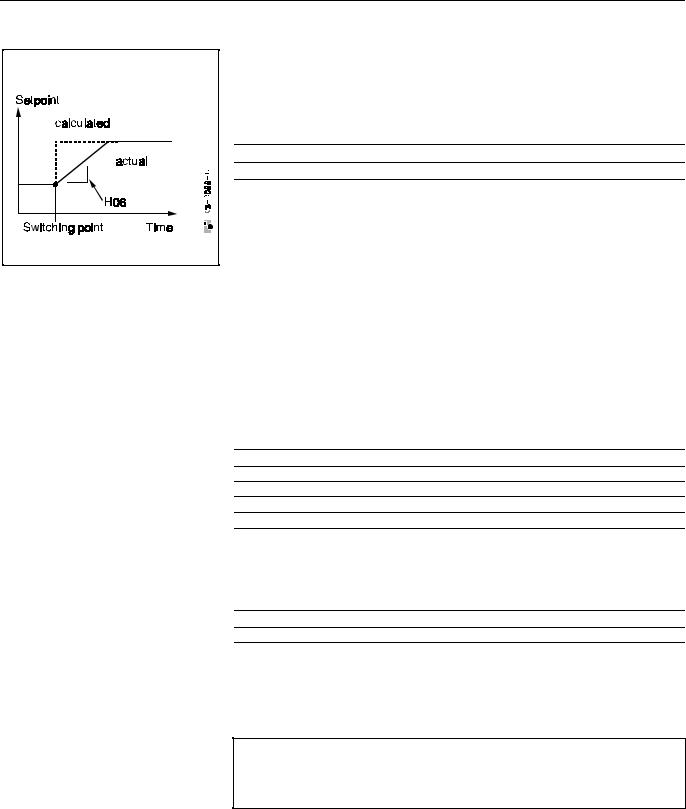
The user can reduce the heating up speed for special applications. By setting a room temperature setpoint ramp (CODE No. 106, 206, 306,406) it is possible to let the room setpoint rise slowly. The cooling down speed is limited correspondingly.
The room equipment and building are conserved by limiting the heating up speed
(application e.g. in church buildings, museums etc.).
The switching point is always the starting point of the ramp.
CODE 106 - 206 - 306 - 406
Room temperature setpoint ramp [K/h]
This function requires a room sensor!
Maximum limitation of the room temperature
With connected room sensor and if an adjustable room temperature limitation is exceeded, the flow temperature setpoint is lowered.
Example:
Room temperature setpoint 20 °C, maximum limitation of the room temperature to 22 °C. It results from this that starting from a room temperature of 22 °C, the flow temperature of the heating circuit constantly starts to decrease. The maximum permissible room limitation setpoint must be set under the CODE No. 105, 205, 305, 405. If the room temperature (actual value) exceeds the room limitation setpoint, then the heating flow temperature setpoint is decreased via the shift factor (CODE No. 122, 222, 322, 422) and the momentary deviation (actual value of the room temperature - room limitation setpoint).
CODE 105 - 205 - 305 - 405
Maximum limitation of the room temperature [°C]
CODE 122 - 222 - 322 - 422
Proportional band of the room temperature control [K/K]
Minimum limitation of the room temperature
If the flow temperature does not reach the room setpoint with connected room sensor and if this is below the set room temperature limit, the flow temperature setpoint is set to 0 °C.
CODE 104 - 204 - 304 - 404
Minimum limitation of the room temperature [°C]
Overtime compensation with TF 26
The set overtime setpoint (CODE No. 107, 207, 307, 407) is active if the TF 26 belonging to the mixing circuit stands at the "Sun" symbol. "TW day" then appears on the operating unit, since the timer no longer has any influence. The night setpoint (CODE No. 108, 208, 308, 408) is used if the TF 26 stands at "NIGHT".
Note: The maximum permissible room temperature always has priority, i.e. overtime setpoints which are larger than the max. permissible room temperature (CODE No. 105, 205, 305, 405) cannot be maintained.
The minimum limitation of the room temperature has the same function. The minimum room temperature is set in CODE 104, 204, 304, 404.
CODE 107 - 207 - 307 - 407 |
→ |
Overtime setpoint for TW intervention |
|
|
[°C] |
CODE 108 - 208 - 308 - 408 |
→ |
Night setpoint for TW intervention |
|
|
|
CODE 104 - 204 - 304 - 404 |
→ |
Minimum room temperature |
|
|
|
CODE 105 - 205 - 305 - 405 |
→ |
Maximum room temperature |
|
|
|
EN 2R-1120 |
14 |
01.04.98 (EN\2R\EN2R1120.DOC) |

MCR 200 - SERVICE INSTRUCTIONS
Overtime compensation via room sensor input
In order to start the overtime function, the room sensor input of the control circuit has to be short circuited for at least 10 seconds. This will start a timer, starts counting back to zero from the time set under
CODE 129 - 229 - 329 - 429
time for overtime function
During this period of time the overtime setpoint under Code 107 - 207 - 307 - 407 is activated.
Statistics
Determining the number of degree days
The number of degree days is required for determining the energy consumption of an appliance for a heating period. The MCR200 controllers can determine the real, system-specific number of degree days. The number of degree days is the product of the heating days of a heating period and the temperature difference between the fixed room setpoint of 18 °C and the mean outside temperature (the base temperature is adjustable, Code 1650).
The calculations required for this are performed by the controller. The corresponding information can be called up in the text field of the operating unit. For this purpose the computer measures the outside temperature every five minutes and averages these measurements at the end of the day.
These measurements are made in the time window from September 1 to May 31, provided the outside temperature is below +15 °C (time window according to VDI 2067 BL 1).
In code 1650 the basic outdoor temperature for the degree day calculation can be set:
CODE 1650
degree day calculation: basic temperature [°C]
Counter for operating hours
One counter each is available in the MCR200 for recording the operating hours of the individual control circuits. The counter registers all times in which the pumps or burners are in operation.
(EN\2R\EN2R1120.DOC) 01.04.98 |
15 |
EN 2R-1120 |
MCR 200 - SERVICE INSTRUCTIONS
External temperature demand
The heating circuit control system also offers the possibility of reacting to external setpoint demand. This external setpoint demand can be triggered by different functions:
1.by a temperature selector
2.by a 0...10 V signal
3.by a switching contact (e.g. of a ventilation device) The settings for the relevant function must be made in Code 117.
External room setpoint
(Code 117, 217, 317, 417 = 1 or 2)
The room setpoint setting of the time program can be overwritten by a temperature selector (TF 26).
The TF 26 has a selector switch with the following functions:
auto |
automatic operation according to time program |
Day |
constant day setpoint (overtime) |
Night |
constant night setpoint |
The setpoints for "Day" and "Night" can be set in the Code Table. The setpoint of the time program and the overtime setpoint can be changed in 1 °C steps with the setting knob of the TF 26.
The TF 26 can be used only for room controlled and outside temperature controlled control.
External temperature demand by 0...10V signal
(Code 117, 217, 317, 417 = 3)
The MCR 200 can be used as pre-control for arbitrary heat consumers. For this purpose a flow setpoint is calculated from a 0...10 V signal (117, 217, 317, 417 = 3) or queried by a contact (117, 217, 317, 417 = 4).
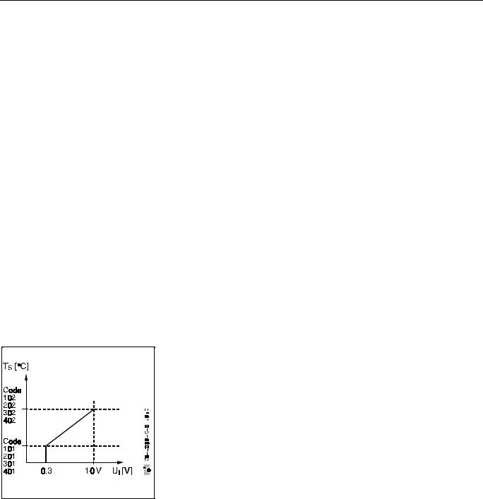
It applies for this that the flow setpoint varies between min. and max. limitation according to the level of the input signal. There is a switch-on threshold of 0.3V. The switching program is not in operation here.
On connection of the 0...10 V signal, the voltage signal of 0.3 to 10 V is converted to minimum flow temperature (101, 201, 301, 401) up to maximum flow temperature (102, 202, 302, 402) (see adjacent Fig.).
The heating circuit pump always runs if the flow setpoint is > 20°C. The janitor function is in operation.
External switching contact mode 1
(Code 117, 217, 317, 417 = 4)
On connection of a contact, the setpoint is calculated by a heating characteristic. With a closed contact, the heating characteristic is calculated according to 107, 207, 307, 407 according to the room setpoint. The temperature limitations 101, 201, 301, 401 and 102, 202, 302, 402 always apply.
The external switching contact has the following meaning:
Closed contact |
The controller works without switching program with the |
|
setpoint from Code No. 107, 207, 307, 407 |
|
as outside temperature controlled controller |
Open contact |
The controller works without switching program with the |
|
setpoint from Code 108 , 208, 308, 408 |
|
as outside temperature controlled controller. |
External switching contact mode 2
(Code 117, 217, 317, 417 = 5)
The external switching contact has the following meaning:
Closed contact |
The controller works without switching program |
|
with the setpoint from Code No. 102 |
Open contact |
The controller works without switching program |
|
with the setpoint from Code 101 |
EN 2R-1120 |
16 |
01.04.98 (EN\2R\EN2R1120.DOC) |
 Loading...