


X4 Series
Operating Instructions and
Maintenance Manual

Alternative language versions are available for download from the Honeywell Analytics website www.honeywellanalytics.com
Alternatieve talen versies zijn electronisch beschikbaar via onze web pagina van Honeywell Analytics: www.honeywellanalytics.com
Les versions alternatives de langue sont disponibles pour le téléchargement du website www.honeywellanalytics.com de Honeywell Analytics
Las versions alternativas de la lengua están disponibles para la transferencia directa del website www.honeywellanalytics.com de Honeywell Analytics
Versioni in alter lingue, incluso l'italiano, sono disponibili e possono essere scaricate dal sito web della Honeywell Analytics www.honeywellanalytics.com
Zusätzliche Sprachen stehen zum Download auf folgender Webseite zur Verfügung. www.honeywellanalytics.com
|
X4 Series |

Important Notice
System configurations of the detector are available with 4, 3, 2, and 1 gas sensor(s) installed in order to provide specific protection for most major industrial applications and compliance requirements. Though this operating manual is provided for the detector with 4 gas sensors installed, the information in the manual also applies to other system configurations of the detector with 3, 2, and 1 gas sensor(s) installed as well (See Section 8 System Configurations Options).
To ensure proper functioning of this product, do not use it until you read and completely understand this operating manual. It contains operating and maintenance procedures to ensure proper detector function. For your safety, it is required to calibrate the detector periodically (See Section 4 Calibration).
Honeywell Analytics can take no responsibility for use of its equipment if it is not used in accordance with the instructions stated in the relevant manual. If further details are required but not provided in this manual, contact Honeywell Analytics or their agent.
Honeywell Analytics shall not be liable for any incidental or consequential damages in connection with any modifications, errors or omissions in this manual.
While every effort has been made to ensure accuracy in this publication, no responsibility can be accepted for errors or omissions.This publication is not intended to form the basis of a contract, and the company reserves the right to amend the design and specifications of the detectors without notice. Note too that data may change as well as legislation, and you are advised to obtain copies of the most recently issued regulations, standards and guidelines.
 Warnings and Cautions
•Substitution of any components may impair intrinsic safety.
•Use only approved memory cards, part # 2566-0435, which are available from Honeywell Analytics. Use of any other manufacturer or type will violate intrinsic safety requirements.
•Activation of the detector after the date on the packaging means less usable life and shorter warranty period.
•Use only approved ‘AA’ Alkaline Batteries, Energizer® E91 or EN91: or use only approved 'AA' NiMH recharchable cells. Quest 1500mAh, order part number 2566-0454 (Quest part number HL-AAC1500). Use of any other manufacturer or type will violate intrinsic safety requirements.
•Use only two new batteries of the same type, when replacing the batteries.
•The optional NiMH rechargeable batteries must be in fully charged condition and replaced as a new pair. Do not attempt to charge the optional NiMH cells in potentially hazardous areas
•Replace batteries as soon as the detector emits a low battery alarm.
•Battery life will be reduced at low temperatures.
•Replace batteries only in an area known to be NON-HAZARDOUS.
•Instrumentcontainsnouserserviceableparts.ContactHoneywellAnalyticsforany servicing requirements.
(cont’d)
X4 Series |
|

•Perform a Self-Test prior to each day’s use (See Section 3-1 Performing a Self-Test).
•Periodicallytestthesensors’responsetogasbyexposingthemonitortoatargetgas concentrationthatexceedsthealarmsetpoints.Verifyproperoperationofaudible, visual and vibrating alarms during this test.
•Use only factory supplied calibration gas for calibration. Accurate calibration can be achieved only if specific concentrations of the correct gases are used.
•Calibration should be carried out in a well-ventilated area to avoid contaminants.
•Calibration cannot be carried out when the detector emits a low battery alarm.
•Do not use the detector in oxygen-enriched atmospheres.
•The flammable sensor’s sensitivity can be adversely affected by exposure to certain substances called “poisons”. Sulfur compounds, phosphorus containing compounds, halogens, silicone or lead containing compounds are examples of such poisons. Every effort should be made to avoid exposure to these substances. When the detector is exposed to such substances, a gas test should be performed on the flammable sensor to verify its accuracy and a calibration performed if necessary.
•Extended exposure of the detector to certain high concentrations of flammable gases and air may stress the flammable detector element, which can seriously affect its performance. If an alarm occurs due to high concentration of flammable gases, recalibration should be performed, or if needed, the sensor replaced.
•Do not use solvents, soap, polishes or any product containing silicon compounds to clean the detector as these can cause damage to the sensors.
•Do not expose the detector to electrical shock and/or severe mechanical shock. When the detector is exposed to such shocks, a check should be performed on the sensors to verify its accuracy and a calibration performed if necessary.
•Disabling one or more installed sensors configures the detector to a 1, 2, or 3-gas unit. No protection is provided for the gas targeted by the disabled sensor(s).
•Do not install or remove the memory card in the detector or attempt to read, download or write to the memory card using a memory card reader and/or computer in potentially hazardous atmospheres.
•Do not remove the batteries from the detector while the power is on.This can cause fatal damage to the optional memory card if installed.
•No gas will be detected while in the set-up mode or the gas exposure status review mode.
•The desktop USB memory card reader and data logging kit are not certified intrinsically safe and must not be used in potentially hazardous atmospheres.
X4 Series

Contacting Honeywell Analytics Customer Business Centers
Americas (Minimax4 series)
400 Sawgrass Corporate Parkway
Suite 100
Sunrise, Florida 33325
Tel: +1 954 514 2700
Toll free: +1 800 538 0363
Fax: +1 954 514 2784
sales@honeywellanalytics.com
Europe and ROW (ImpulseX4 series)
Wilstrasse 11-U11
Ch-8610 Uster
Switzerland
Tel: +41 (0)1 943 4300
Fax: +41 (0) 1 943 4398
sales@honeywellanalytics.co.uk
Or visit our web site at www.honeywellanalytics.com
X4 Series

Additional Warnings and Cautions for Canadian Certification and Other Global Certification Bodies
 WARNING
Substitution of any components may impair intrinsic safety.
 AVERTISSEMENT
La substitution de composants peut compromettre la sécurité intrinsèque.
 CAUTION
For safety reasons this equipment must be operated and serviced by qualified personnel only. Read and understand instruction manual completely before operating or servicing.
 ATTENTION
Pour des raisons de sécurité, cet équipement doit être utilisé, entretenu et réparé uniquement par un personnel qualifié. Étudier le manuel d’instructions en entier avant d’utiliser, ’entretenir ou de réparer l’équipement.
 CAUTION
High off-scale reading may indicate explosive concentration.
 ATTENTION
Des lectures supérieures à l’échellepeuvent indiquer des concentrations explosives.
 CAUTION
Before each day’s usage sensitivity must be tested on a known concentration of methane equivalent to 25-50%LEL. Accuracy must be within +/-20% of actual concentration. Accuracy may be corrected by performing proper calibration on the detector.
 ATTENTION
Chaque jour, avant toute utilisation, tester la sensibilité sur une concentration connue de méthane équivalente à 25-50% LEL. La précision doit être comprise dans une plage de +/-20% de concentration réelle. A précision peut être corrigée en effectuant un étalonnage approprié du détecteur.
X4 Series

 WARNING
Under proper calibration procedures, repetitive calibration failures could indicate that the sensor is either approaching its end of life, or it has been seriously contaminated, or both.
 AVERTISSEMENT
Si Les Procédures D’étalonnage Sont Bien Respectées, Des Défauts D’étalonnage Répétitifs Peuvent Indiquer Que Le Capteur Arrive En Fin De Vie Ou Qu’il A Été Sérieusement Contaminé, Ou Les Deux.
 WARNING
The detector must not be removed from its rubber boot during transportation or use, and if the rubber boot is removed for servicing or any other reason, it must be replaced before the instrument is placed back in service.
 AVERTISSEMENT
Le support en caoutchouc du détecteur ne doit jamais être retiré pendant son utilisation ou son transport. Si pour un quelconque motif, d’entretien ou
autre, cette protection a été retirée, elle doit toujours être remise en place avant d’utiliser l’instrument.
Only the combustible gas detection portion of this instrument has been assessed for performance.
S e u l l e f o n c t i o n n e m e n t d e l a p a r t i e d é t e c t i o n d e g a z combustible de cet instrument a été évalué
The csa symbol, “exia”, represents intrinsically safe, or in french, sécurité intrinsèque.
Le symbole csa “exia” signifie “sécurité intrinsèque”
 WARNING
Use only the approved Honeywell Analytics charger (part number 2566-0484) when charging the sealed rechargeable battery pack (part number 2566-0482 for Minimax4 series and part number 2566-0462 for Impulse X4 series). Use of any other charger will void the intrinsic safety certification of the instrument.
 AVERTISSEMENT
Utiliser uniquement le chargeur Honeywell Analytics homologué (référence 25660484) lors de la mise en charge du kit batterie étanche rechargeable (référence 2566-0482 pour la série Minimax4 et référence 2566-0462 pour la série Impulse X4). En cas d’utilisation de tout autre chargeur, la certification de sécurité intrinsèque de l’instrument sera nulle et non avenue.
X4 Series |
|

 WARNING
Use only the Honeywell Analytics supplied ac adapter (part number 2566-0483) to connect to the cradle charger (part number 2566-0484).
 AVERTISSEMENT
Utiliser uniquement l’adaptateur à courant alternatif Honeywell Analytics fourni (référence 2566-0483) pour connecter l’instrument au chargeur socle (référence 2566-0484).
 WARNING
The charger units contain no user serviceable parts. No attempt should be made to alter or repair the charger.
 AVERTISSEMENT
Les chargeurs ne comportent pas de pièces d’entretien sur lesquelles l’utilisateur peut intervenir. Ne pas essayer de modifier ni de réparer le chargeur.
X4 Series

Table of Contents
1. Introduction 11
1-1. Product Overview 11
1-2. Basic Button Operation 12
1-3. LCD Display 12
1-4. Standard Accessories 13
2. Turning the Detector On and Off 13
2-1. Turning the Detector On 13
2-1-1. Displaying the Firmware Version 13 2-1-2. Clearing the STEL and TWA Values 14 2-1-3. Checking the Memory Card 14 2-1-4. Power-Up Self-Test 15 2-1-5. Checking the Calibration Due Date 15
2-2. Turning the Detector Off 15
3. Operation 16 3-1. Performing a Self-Test 16 3-2. Measuring Mode 17
3-2-1. Flipping the Display 18
3-3. Testing Sensors and Alarms (Bump Testing) 18 3-4. Gas Alarms 18
3-4-1. Gas Alarms for the Minimax4 series 19 3-4-2. Gas Alarms for the ImpulseX4 series 19
3-5. Gas Exposure Status Review 21
3-6. Confidence Flash/Beep 22
3-7. Low Battery 22
3-8. Data Logging 22
4. Calibration 24
4-1. Calibration Prompt 24 4-2. Zero Calibration (Span Calibration for Oxygen) 24
4-3. Span Calibration (for Flammable and Toxic Sensors Only) 25
4-3-1. Pass Code Input 26 4-3-2. Span Gas Information 26 4-3-3. Span Gas Setting 27 4-3-4. Gas Search and Countdown 27 4-3-5. Span Calibration Result 28
5. Set-Up Mode 29 5-1. Entering the Set-Up Mode 30 5-2. Changing the Detector Set-Up 31 5-3. Exiting the Set-Up Mode 31
X4 Series

6. Maintenance 32
6-1. Replacing the Batteries 32 6-2. Installing or Removing the Memory Card 33 6-4. Replacing the Expired Sensor 34 7. Optional Accessories 35
8. System Configuration Options 36 8-1. System Configurations for the Minimax4 series 36 8-2. System Configurations for the ImpulseX4 series 36 Appendix A 37 A-1. Calibration Mode Menu Structure 1/2 37 A-2. Calibration Mode Menu Structure 2/2 38 A-3. Set-up Mode Menu Structure 1/4 39 A-4. Set-up Mode Menu Structure 2/4 40 A-5. Set-up Mode Menu Structure 3/4 41 A-6. Set-up Mode Menu Structure 4/4 42 Appendix B 43 B-1. Sensor Cross-Sensitivity 43
B-1-1. H2S and CO SureCell Cross-Sensitivity 43 B-1-2. O2 Cross-Sensitivity 43 B-1-3. Flammable Cross-Sensitivity 44
B-2. Flammable Lower Explosive Limit 45 Appendix C 46 C-1. Warranty 46 C-2. Accuracy Statement 47 C-3. Declaration 48
C-3-1. Declaration for the Minimax4 series 48 C-3-2. Declaration for the ImpulseX4 series 49
Appendix D 50 D-1. Specifications 50
D-1-1. Specifications for the Minimax4 series 50 D-1-2. Specifications for the ImpulseX4 series 51
10 |
X4 Series |
1. Introduction
The X4 series is an easy to use personal gas detector, designed for monitoring the atmosphere for potentially hazardous levels of flammables, oxygen, carbon monoxide, and hydrogen sulfide. It uses a front-mounted LCD display to show readings of the gases being measured and other useful information. A loud audible alarm and bright visual alarm are used to warn users when the concentrations of measured gases exceed the alarm set points. It has built-in cell decay compensation, thermal shock protection, and Reflex™, a patented cell check technique, for maximum reliability.
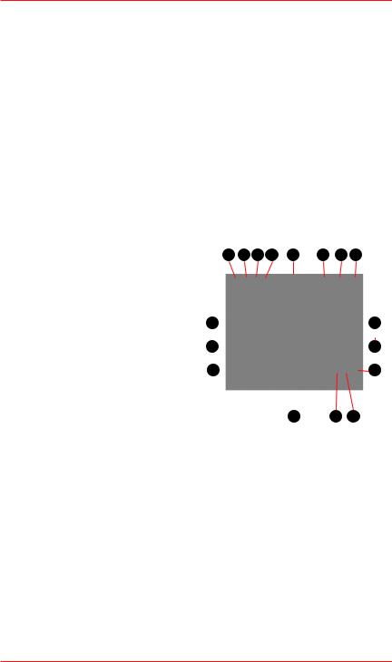
1-1. Product Overview
Threaded Hole for
Flow Adaptor
Visual Alarm
Sensor Grille
ON/OFF Button 
Audible Alarm
LCD Display
Left |
Front |
Crocodile Clip
UP Button 
Locking Tab
DOWN Button
Battery Holder
Right |
Bottom |
X4 Series |
11 |
1-2. Basic Button Operation
ON/OFF button
•Turn on the detector
•Turn off the detector
•Self-Test
•ZERO calibration
•SPAN calibration
•Accept a user set-up change
•Latched Alarm acknowledgement
1-3. LCD Display
1. Test Pass Icon
. Test Fail Icon
. High Peak Icon
4.Low Peak Icon (for O2 only)
5.Alarm Icon
6.Data Logging Icon
. Battery Icon
8.Pass Code Protection Icon
9.%Vol Unit Icon
10.%LEL Unit Icon
11.STEL Icon
1 .TWA Icon
1 .Alarm Level 1 Icon 
Alarm Level 2 Icon 
(for flammable and toxic)
14.Zero Calibration Icon  Span Calibration Icon
15.Gas Label Icon
16.O2 Deficiency Alarm Icon 1 .O2 Excess Alarm Icon
UP button
•Scroll through status or menu options
•Increase value
•Activate/deactivate flipped display
•Activate backlight
DOWN button
•Scroll through status or menu options
•Decrease value
•Activate backlight
1 |
2 |
3 |
4 |
5 |
6 |
7 |
8 |
17 |
|
|
|
|
|
9 |
||||
|
|
|
|
|
|
|
|
|
|
|
|
|
|
|
|
|
|
|
|
|
|
|
|
|
|
|
|
|
|
|
|
|
16 |
|
|
|
|
|
10 |
||||
15 |
|
|
|
|
|
11 |
||||
|
|
|
|
|
||||||
|
|
13 12 |
|
|||||||
14 |
||||||||||
The LCD display has a backlight that will operate automatically whenever an alarm occurs, and also whenever any button is pressed. To turn on the backlight while staying in the measuring mode in a low light area, press the UP or DOWN button once.
12 |
X4 Series |

1-4. Standard Accessories
The items listed below are included with the X4 series. For damaged or missing parts, contact Honeywell Analytics or their agent.
Part No. |
Description |
Qty |
|
|
|
2566-0424 |
Calibration Certificate |
1 |
|
|
|
2566-0422 |
Quick Start Guide |
1 |
|
|
|
2566-0433 |
Alkaline Batteries (1.5V AA), Energizer® E91 or EN91 |
2 |
2566-0426N |
Flow Adaptor (Neotronics) |
1 |
|
|
|
2566-0426L |
Flow Adaptor (Lumidor) |
1 |
|
|
|
2566-0480 |
Protective Rubber Boot (Neotronics) |
1 |
|
|
|
2566-0445 |
Protective Rubber Boot (Lumidor) |
1 |
|
|
|
2566-0443 |
Tubing (45 cm/18”) |
1 |
|
|
|
2566K0130 |
Crocodile Clip Kit |
1 |
|
|
|
2566-0420 |
Manual |
1 |
|
|
|
2. Turning the Detector On and Off
Before turning the detector on for the first time, you will need to install two “AA” alkaline (Energizer® E91 or EN91) batteries (See Section 6-1 Replacing the Batteries).
A sealed rechargeable battery pack (part number 2566-0482 for the Minimax, and 2566-0462 for the Impulse) is also available (See Section 7 Optional Accessories)
If you plan on logging data and have a memory card, now is also a good time to install the card (See Section 6-2 Installing or Removing the Memory Card).
2-1. Turning the Detector On
Press and hold the ON/OFF button for 2 seconds and the detector will turn on.
2-1-1. Displaying the Firmware Version
The detector will display the version of the firmware.
X4 Series |
13 |

2-1-2. Clearing the STEL and TWA Values
When the non-zero STEL and/or TWA values are carried over from the previous measurement, a “Delete no” prompt will be displayed with the gas labels and the STEL and TWA icons. (When the STEL and TWA values are zero, the “Delete no” prompt will not be displayed.)
Press the UP or DOWN buttons to scroll to “no” or “YES” and press the ON/OFF button to select.
or
When “no” is selected, the recorded STEL and TWA values will be used as initial STEL and TWA values for the current session. When “YES” is selected, the STEL and TWA values will be cleared.
2-1-3. Checking the Memory Card
The detector will check the memory card in the memory card slot. When a properly formatted FAT16 memory card with a data full condition is detected, a“Data Fu”message will be displayed followed by a “Delete no” prompt. (When a properly formatted FAT16 memory card is not full of data, the “Data Fu” message and the “Delete no” prompt will not be displayed).
Press the UP or DOWN buttons to scroll to “no” or “YES” and press the ON/OFF button to select.
or
14 |
X4 Series |

When “no” is selected, the detector keeps the current data file and the Data Logging icon  will not be displayed in the measuring mode which indicates that no data is being logged. When “Yes” is selected, the detector deletes the current data file and creates a new file for data logging. The Data Logging icon
  will be displayed in the measuring mode which indicates that data is being logged.
The detector does not support either FAT32 or NTFS format for the memory card. When a memory card with non-FAT16 format is detected, a “Card Er” message will be displayed with a single beep. (When a properly formatted FAT16 memory card is detected, a “Card Er” message will not be displayed.)
The Data Logging icon  will not be displayed in the measuring mode which indicates that no data is being logged.
2-1-4. Power-Up Self-Test
The detector will beep and perform a power-up Self-Test. If the detector passes the Self-Test, the Test Pass icon  is displayed. If the Test Fail icon
  is displayed and the Test Pass icon
  blinks with 1 beep and 1 flash every 5 seconds, then the detector has failed the Self-Test (See Section 3-1 Performing a Self-Test).
2-1-5. Checking the Calibration Due Date
The detector checks the calibration due date stored in the detector after the Power-Up Self-Test. When the number of days remaining until calibration is due reaches zero, a "CAL dUE dAY 0" message will be displayed to remind the user that a calibration needs to be performed.
To perform the calibration, see Section 4 Calibration.
2-2. Turning the Detector Off
To turn off the detector, press and hold the ON/OFF button while in the measuring mode. A countdown will be displayed for 5 seconds, and then the detector will beep and turn off.
X4 Series |
15 |

3. Operation
3-1. Performing a Self-Test
When the ON/OFF button is pressed, the detector checks the sensor, circuit, batteries, and audible, visual, and vibrating alarms.
The detector will do the following:
=Turn on all the display elements
=Test the audible, visual, and vibrating alarms
=Check the battery, electronic circuit and sensors
aa
•Display the level 1 (flammable and toxic low, O2 excess) and level 2 (flammable and toxic high, O2 deficiency) alarm set points
•Display the STEL and TWA alarm set points (for CO & H2S only).
|
a |
a |
a |
Level 1 |
Level 2 |
|
STEL |
TWA
*Examples shown for default settings of each gas for the Minimax4 series.
16 |
X4 Series |
 Loading...