


Gas Detection
Tubes and Sampling
Handbook

Table Of Contents
1. |
INTRODUCTION |
.................................................................................... |
3 |
|
2. QUALITY ASSURANCE ...................................PROCEDURES |
5 |
|||
3. |
OPERATION OF ............................DETECTION TUBES AND PUMPS |
7 |
||
|
3.1 |
Hand Pump Description................................................................... |
8 |
|
|
3.2 |
Tube Measurements………………………………………….............. 8 |
||
|
|
3.2.1 Tube .....................................Description and Packaging |
8 |
|
|
|
3.2.2 Testing ........................................Hand Pump for Leaks |
10 |
|
|
|
3.2.3 Measurement ...............................................Procedure |
10 |
|
|
|
3.2.4 Reading Tubes……………………………………............ 13 |
||
|
3.3 |
Maintenance ..........................of the LP-1200 Piston Hand Pump |
14 |
|
|
3.4 |
Selection of Sampling .........................................................Pump |
15 |
|
|
3.5 |
Operation and ..........................Maintenance of Remote Sampler |
15 |
|
4. |
TECHNICAL INFORMATION................................................................ |
19 |
||
|
4.1 |
Theory of Operation....................................................................... |
19 |
|
|
4.2 |
Explanation of ...........................................................Data Sheets |
20 |
|
|
4.3 |
Humidity, Temperature, .....................Pressure and Matrix Effects |
22 |
|
5. |
DATA SHEETS FOR .................................GAS DETECTION TUBES |
26 |
||
6. |
SPECIALTY TUBES............................................................................ |
103 |
||
|
6.1 |
Smoke Generating ............................................................Tubes |
103 |
|
7. |
APPENDICES..................................................................................... |
|
105 |
|
|
7.1 |
Appendix 1. .............................................Alphabetical Tube List |
105 |
|
|
7.2 |
Appendix 2. .......................................Tube List by Part Number |
107 |
|
|
7.3 |
Appendix 3. ..........................................Detectable Compounds |
109 |
|
|
7.4 |
Appendix 4. .............. |
Equivalent Tubes of Other Manufacturers |
114 |
|
7.5 |
Appendix 5. ........... |
Conversion Factors for Gas Concentrations |
117 |
|
7.6 |
Appendix 6. ................................... |
Humidity Conversion Tables |
118 |
|
7.7 |
Appendix 7. ................................................................. |
Warranty |
119 |
|
7.8 |
Appendix 8. ................................. |
Honeywell Analytics Contacts |
120 |
CONTENTS OF TABLE
www.honeywellanalytics.com |
1 |
INTRODUCTION
WARNING
The products described herein will perform as designed only if they are used, maintained, and serviced in accordance with the manufacturer’s instructions. Failure to use, maintain, and operate products properly can result in dangerously inaccurate readings.
CAUTION: For safety reasons, the equipment described herein must be operated and serviced by qualified personnel only.
Read and understand this instruction manual completely before operating or servicing.
ATTENTION: Pour des raisons de sécurité, ces équipments Doivent être utilisés, entretenus et réparés uniquement par un personnel qualifié. Étudier le manuel d’instructions en entier avant d’utiliser, d’entretenir ou de réparer l’équipement.
Custom Tubes
Please contact Honeywell about the availability of custom tubes not included in this handbook. Contact information is included on page 128.
Application & Technical Notes
Honeywell’s web site includes the Application Notes and Technical Notes cited in this handbook, as well as many others. Visit our web site at: www. honeywellanalytics.com.
© 2014 by Honeywell International. This handbook is fully protected by copyright, and no part of it may be reproduced in any form without the express written consent of Honeywell, 3775 N. First St., San Jose, CA 95134-1708 USA.
2 |
www.honeywellanalytics.com |

1. INTRODUCTION
This handbook describes the use and performance of gas detection tubes and sampling pumps manufactured by Honeywell. Honeywell began manufacturing gas detection tubes in 1997 and is adding many new tubes to its product line each year. Modern production facilities and techniques allow us to offer high-quality tubes at a highly competitive price.
Gas detection tubes operate in the following manner: An air sample is drawn through a tube containing a reagent, causing a color change. The concentration is then read from the length of the color stain in the reagent. The advantages of detection tubes over other analytical methods are simplicity of use, rapid response, low cost, and very low maintenance. Because each batch of Honeywell tubes is pre-calibrated, no calibration equipment is necessary. Errors are prevented by directly marking the calibration information on each tube, and accuracy is further ensured by controlling the volume of air sampled. Honeywell tubes are primarily of the narrow bore type and are designed for use with a Honeywell handoperated piston pump.
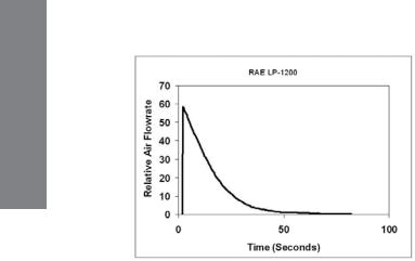
Air sampling can also be performed using piston pumps, which latch into a precisely defined position to fix the volume. These pumps pull a strong vacuum initially and thus create substantially higher flowrate than the bellows pumps. Piston pumps generate a high flow initially followed by an approximately exponential decay, whereas bellows pumps provide a more steady flow initially followed by the slow decay. The difference in flow patterns means that the pumps cannot be interchanged between types. For example, piston pumps sometime cause a smearing of the color stain when used on tubes originally developed for bellows pumps. This occurs because the higher flow rates do not allow enough contact time to give sharp endpoints when a piston pump is used.
For a period of time, attempts were made to improve accuracy by stabilizing the flow rate using rate-limiting orifices. Some manufacturers supplied as many as four different orifice sizes to match the particular tube being used. However, exchanging limiting orifices proved to be cumbersome and unnecessary as long as enough contact time was allowed to avoid smearing the stain. Therefore, limiting orifices have fallen out of use and it has now become standard practice to build the flow restriction into the tube itself. This is done by selecting the particle size of the support material and type of end plug that give a sampling time appropriate for the particular chemical reaction of the tube.
INTRODUCTION
www.honeywellanalytics.com |
3 |

INTRODUCTION
As a result of these developments, modern tube/pump systems have stabilized into two categories: (1) low-vacuum bellows pumps with less flow resistance in the tubes, by virtue of being wider (~7 mm o.d.) and having larger particles, and (2) high-vacuum piston pumps with greater resistance in the tubes by being narrower (~5 mm) and having smaller particles. The bellows pump/tube systems tend to have faster sampling but require more pump strokes to complete a measurement, whereas the piston pump systems generally need fewer strokes but longer sampling time per stroke. Honeywell tubes are primarily of the narrow-bore type and are designed for use with a piston sampling pump.
4 |
www.honeywellanalytics.com |
2. QUALITY ASSURANCE PROCEDURES FOR GAS DETECTION TUBE MANUFACTURE
All Honeywell gas detection tubes are developed in an ISO 9001 certified facility and manufactured in an ISO 9001 certified factory. All procedures, work instructions, and quality records are documented and maintained to ensure tube quality. The procedures are outlined below.
A. |
Tube Selection. Glass tubing is selected to fit a standard bore size to |
|
|
|
ensure uniform length of color change. |
|
|
B. |
Support Preparation. Silica, alumina, and other support materials |
|
|
QUALITY |
|||
|
are chosen from the highest quality available and sieved to yield a |
||
|
requirements of the tube reactions. |
||
|
narrow particle size distribution. The supports are then further purified |
|
|
|
as necessary and dried to well-defined levels depending on the |
ASSURANCE |
|
C. Reagent Loading. Chemicals are chosen according to strict purity |
|||
|
|||
|
standards and loaded onto the support materials. Deposition of the |
|
|
|
chemicals onto the support follows a protocol developed specifically |
|
|
|
for each tube type. The loaded support material is then dried as |
|
|
|
needed for the reaction. |
|
|
D. |
Tube Filling and Sealing. End plugs are selected of materials that |
|
|
|
|||
|
do not react with the reagent. The tubes are filled under conditions |
|
|
|
that minimize exposure to air, water vapor, or other gases that may |
|
|
|
affect the quality of the tubes. The tubes are then packed tightly by |
|
|
|
a combination of shaking and physical compression. The ends of the |
|
|
|
tubes are then melted closed using an automated flame sealer. Any |
|
|
|
necessary inert atmosphere is maintained through the tube-sealing |
|
|
|
process. |
|
|
E. |
Calibration. Each batch of tubes is calibrated independently of other |
|
|
|
batches. A series of standard gases are purchased or prepared by a |
|
|
|
variety of methods, including flow dilution of gas primary standards, |
|
|
|
permeation tubes, and diffusion tubes, or static dilution from liquid or |
|
|
|
gas primary standards. Multiple tubes are used to determine each |
|
|
|
calibration position, and these are then printed onto each tube in the |
|
|
|
batch with an automated printing machine. |
|
|
www.honeywellanalytics.com |
5 |
F.Packaging. The tubes and their technical data sheets are packed into labeled boxes with protective corrugated cardboard.
G.Quality Control Sampling Plan. A portion of each batch is sent to the Honeywell's Quality Assurance Laboratory for independent QA testing. The most widely used tubes pass the accuracy criterion of ≤±15% of length of stain. A separate set of tubes is stored in the QA laboratory and the manufacturing facility for evaluation at later dates, if necessary.
H.Accuracy and Precision. The accuracy is measured by testing at least five tubes and calculating the average deviation from the standard gas value. The precision is calculated as the standard deviation from the average value of the five measurements. All tubes meet the accuracy and precision criteria listed in Table 2-1:
Table 2-1. Honeywell Tube Accuracy and Precision Specifications
|
|
|
Conc. |
|
Accuracy |
|
|
|
Tube Type |
Range |
Precision |
|
|
|
>20-100% |
≤20% Full |
||||
|
|
|
|
|
||
|
|
|
|
|
Full Scale |
Scale |
|
|
CO, CO2, H2O , H2S, NH3, |
>50 ppm |
10% |
10% |
12% |
|
||||||
|
|
PH3, SO2 |
|
|
|
|
|
|
CO, H2O , H2S, NH3, PH3, |
<50 ppm |
12% |
15% |
20% |
OPERATION |
|
SO2 |
|
|
|
|
|
CO, Acetone, Benzene, |
All |
12% |
15% |
20% |
|
|
|
|||||
|
|
MEK, Toluene, Xylene |
|
|
|
|
|
|
Cl2, ClO2, HCN, HCl, HF, |
|
|
|
|
|
|
NOx, NO2, RSH, RNH2, |
|
|
|
|
|
|
Butane, Diesel, Ethanol, |
All |
20% |
20% |
25% |
|
|
Formaldehyde, Gasoline, |
||||
|
|
Methyl Bromide, Ozone, |
|
|
|
|
|
|
Phenol, Trichloroethylene, |
|
|
|
|
|
|
Vinyl Chloride, others |
|
|
|
|
I.Interim Storage. Only batches that pass all quality assurance procedures are sent to interim storage, where they are maintained at 3-7°C (37 - 45°F) in darkness until shipment.
6 |
www.honeywellanalytics.com |

3. OPERATION OF DETECTION TUBES & PUMPS
CAUTION:
Wear safety glasses and gloves when opening tubes or handling open tubes with sharp edges. Failure to wear protective equipment may lead to cuts and other severe injuries to eyes and hands.
Always test the pump for leaks immediately before using it for a series of measurements. Failure to test the pump for leakage may lead to dangerously inaccurate readings.
Avoid contact with tube contents in case of accidental breakage. Exposure to tube contents can result in significant health hazards.
Dispose of spent tubes according to local regulations.
Review the reaction principle and other information listed in the Gas Detection Tube Data Sheet supplied to identify materials that may require special disposal procedures. (Data Sheets for all currently available Honeywell tubes are included in Chapter 5.)
OPERATION
www.honeywellanalytics.com |
7 |
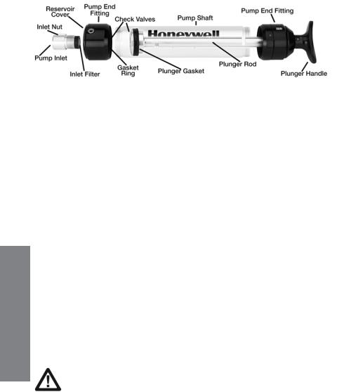
3.1Hand Pump Description
OPERATION
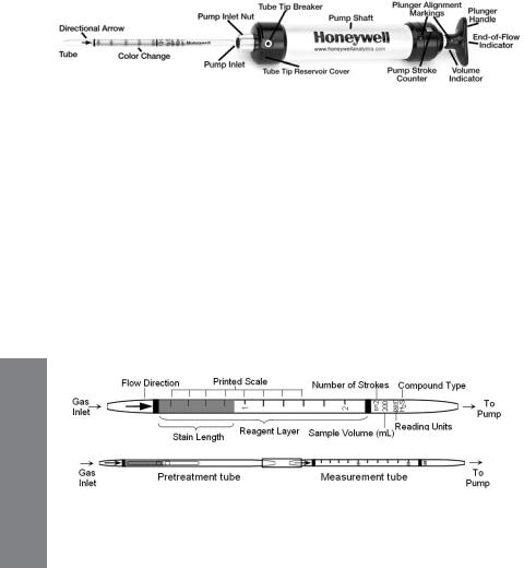
Figure 3-1. LP-1200 Hand Pump with tube inserted.
The LP-1200 is a piston-type hand pump that draws a fixed volume of gas, selectable at either 50 mL or 100 mL by rotating the handle. A tight vacuum seal is formed by a greased plunger gasket. The tapered rubber inlet accommodates a range of tube diameters for different types of tubes.
The inlet filter prevents glass pieces and dust from entering the shaft. An end-of-flow indicator in the handle turns white when the gas sampling is complete. A pump stroke counter is rotated to keep track of the number of strokes completed.
3.2Tube Measurements
3.2.1 Tube Description & Packaging
Figure 3-2. Gas detection tube parts description. Top: Standard single tube. Bottom: Pretreatment tube connected to measurement tube with rubber connector.
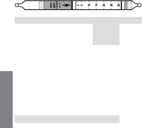
1.Tube and Box. Figure 3-2 shows the key components of a Honeywell gas detection tube. The tubes are typically packaged in a box of 10 tubes. Each box has quick instructions on the back. Some tubes require preconditioning of the gas and are packaged with 5 pretreatment tubes and 5 measurement tubes for a total of 5 measurements. The concentration scale is printed on the tube and an arrow indicates the direction in which the gas must enter. The standard number of 100 mL
8 |
www.honeywellanalytics.com |
strokes is indicated on one side, along with the total sample volume, the unit of measure, the gas type, and the batch number.
2.Data Sheet. Each box is packaged with a Data Sheet that provides detailed information on the tube performance. Figure 3-3 is an excerpt of a typical data sheet. Complete data sheets are provided in Chapter 5 and discussed in detail in Chapters 4.2 and 4.3.
Gas Detection Tube Data Sheet |
|
|
|||
Hydrogen Sulfide |
H2S |
No. H-10-103-18 |
|
||
|
|
|
|
|
|
|
Extended |
Standard |
Extended |
|
|
|
|
Range |
Range |
Range |
|
Range (ppmv) |
12.5 - 125 |
25 - 250 |
50 - 500 |
|
|
No. of Pump Strokes |
|
2 |
1 |
0.5 |
|
Sample Volume (mL) |
|
200 |
100 |
50 |
|
Sample Time (min) |
|
2 x 1 |
1 |
1 |
|
Correction Factor (CF) |
|
0.5 |
1 |
2 |
|
Figure 3-3. Excerpt of a Tube Data Sheet |
|
|
|||
3. Part Number. The 7-digit part number is indicated on the top right of |
|
||||
the data sheet. The second 3 digits indicate the tube chemical type, |
|
||||
and the last two digits number indicate the approximate range of the |
|
||||
tube. The higher the number, the higher the range. |
|
OPERATION |
|||
or larger sample volume. In such cases, the scale reading must be |
|||||
4. Sampling Volume and Time. |
Using the standard number of pump |
|
|||
strokes, the concentration of the gas is read from stain length directly matched to the printed scale after the listed sampling time has elapsed. However, the range of the tube may be extended by using a smaller
multiplied by a Correction Factor (CF) to adjust for the different sample size. For example, the Honeywell H-10-103-18 hydrogen sulfide tube has a standard range of 25-250 ppm. When used with the standard one stroke, the readings will correspond directly to the printed scale on the tube. When used with half a stroke, a Correction Factor (CF) of 2 is applied. An observed reading of 50 ppm then corresponds to an actual concentration of:
50 x 2 = 100 ppm
www.honeywellanalytics.com |
9 |
5.Cross-sensitivity. Gas detection tubes are generally quite selective, but some compounds may interfere in the measurements. The Data Sheet lists possible interfering compounds; others may also exist. In most cases these compounds increase the stain length, but in some cases they decrease the stain length. The user must be aware of potential interferences, or incorrect readings may result.
3.2.2 Testing Hand Pump For Leaks
Before a series of measurements, the pump used must be tested for leaks. Follow this procedure:
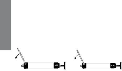
1.Insert an unopened tube snugly into the inlet of the aspirating pump.
2.Align the red dot on the plunger with the red dot on the pump shaft.
3.Pull the plunger one full stroke and wait 2 minutes.
4.Rotate the plunger dot away from the pump shaft alignment mark, and allow the plunger to be drawn back into the pump shaft. Keep your hand on the shaft to keep it from snapping back too suddenly.
There are no leaks if the plunger returns to within 3 mm of its original position. If a leak is detected, refer to Section 3.3 for maintenance procedures.
3.2.3 Measurement Procedure
OPERATION |
1. Break both ends of a new detection tube using the tip breaker on the |
|
|
|
side of the pump. Insert the tube until it stops, and then back off about 1 |
|
mm before breaking off the tip. The latter procedure allows the tip to fall |
|
into the tip reservoir at the end of the pump shaft. The reservoir can be |
|
emptied by opening the rubber cover on the opposite side of the pump. |
Break tube open at both ends.
10 |
www.honeywellanalytics.com |
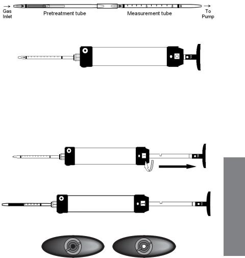
2.In cases where a pre-tube is provided (e.g., Benzene H-10-101-01 and NOx H-10-109-20), connect the pre-tube to the measurement tube using the rubber connector in the direction indicated on the tube.
3.Insert the measurement tube securely into the rubber pump inlet. Point the tube arrow towards the pump (see Figs. 3-1 and 3-2).
Insert open tube with arrow pointing towards pump.
4.Select the sample volume desired and align the red dot on the plunger with the red dot on the pump shaft. Pull the handle quickly until it latches at ½ or 1 full stroke (50 or 100 mL) and wait for the sampling time indicated on the data sheet to allow the air to be drawn through the tube. The end-of-flow indicator is dark during sampling. Flow is complete when the end-of-flow indicator returns to its white color.
Withdraw plunger sharply until it locks in place, and rotate stroke counter.
Wait for indicated sampling time when end-of-flow indicator turns white.
End-of-flow indicator is dark when sampling (left) and white when sampling is complete (right).
OPERATION
www.honeywellanalytics.com |
11 |
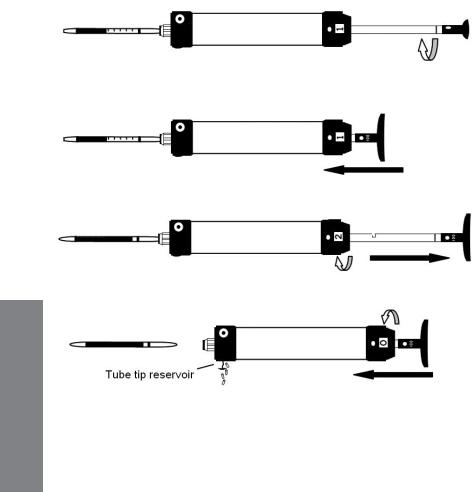
5.For additional pump strokes, rotate the handle ¼ turn clockwise or counterclockwise and push it back fully without removing the tube from the pump. Then repeat Step 4.
If additional strokes are needed, rotate plunger 90 degrees.
Push plunger back into pump shaft without removing tube.
Withdraw plunger for second stroke and repeat strokes as necessary.
OPERATION
Remove and read tube; return plunger and stroke counter to original position; empty tube tip reservoir as necessary.
12 |
www.honeywellanalytics.com |
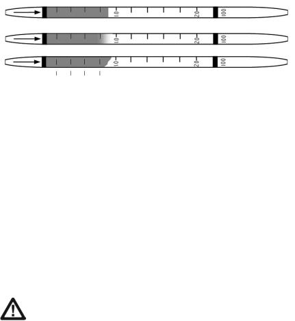
3.2.4 Reading Tubes
1.The concentration of the compound being measured is read directly from the scale printed on the tube.
2.The reading is taken as the furthest distance along the tube that the color change just becomes visible. If the leading edge is diagonal instead of perpendicular to the axis of the tube, use the average of the minimum and maximum values. The three tubes shown in Figure 3-4 are all read as 0.9.
Figure 3-4. Reading of various types of endpoints after sampling.
3. |
Read the tube immediately after gas sampling, as colors may change, |
|
|
fade, or disperse with time. |
|
|
|
|
4. |
If a non-standard number of pump strokes was used for sampling, |
|
|
multiply the reading by the Correction Factor given on the tube Data |
OPERATION |
|
Factor(s) (CF) to obtain the true concentration. For more details and a |
|
|
Sheet (Chapter 5). |
|
5. |
If humidity and temperature corrections are necessary as indicated on |
|
|
the Data Sheets, multiply the observed readings by the given Correction |
|
|
theoretical discussion, see Chapter 4.3 on the effects of humidity and |
|
|
temperature. |
|
6. |
The user must be aware of potential interfering compounds in the tube |
|
|
||
|
measurements. Interferences can be either positive or negative. |
|
CAUTION: Always examine the data sheet and other available information for possible interferences. Failure to consider interferences may lead to dangerously inaccurate readings.
www.honeywellanalytics.com |
13 |
3.3 Maintenance of the LP-1200 Piston Hand Pump
Figure 3-5. Transparent view of LP-1200 pump showing internal parts.
1. Tube Tip Reservoir
Remove the tube tip reservoir cover as needed to empty the broken glass reservoir that is in the pump end fitting.
2. Pump Inlet and Filter
The rubber pump inlet can become worn with use and result in leaks. Unscrew the pump inlet nut and replace the rubber inlet. If the inlet is not replaced, inspect the inlet filter and replace or clean the filter when it becomes visibly dirty or if the end-of-flow indicator on the pump shows that the flow takes longer than recommended on the tube box.
3. Pump Mechanism
The plunger gasket may leak if it is worn or not well lubricated. To replace the gasket:
OPERATION |
1. |
Unscrew the pump end fitting on the handle side. |
|
2. |
Pull the plunger out of the pump shaft. |
||
|
|||
|
3. |
Replace the gasket. |
|
|
4. |
Carefully push the plunger back into the shaft. Use a fine |
|
|
|
screwdriver or tweezers to help ease the gasket into the shaft. |
|
|
5. |
Lubricate the inside of the shaft with vacuum grease to ensure |
|
|
|
a good seal. |
Caution: Do not overtighten the plunger gasket. It could cause a sudden loss of vacuum.
The inlet check valve may cause leaks if worn or not lubricated.
Unscrew the end fitting on the inlet side and pull out the disk-shaped rubber-inlet check valve. Replace as necessary, adding a light coat of grease around the hole.
14 |
www.honeywellanalytics.com |

Replace the outlet check valve gasket if there is resistance on the return stroke. Using the special tool or needle-nose pliers, unscrew the plunger tip from the plunger rod. Replace the O-ring, check valve gasket as necessary, and reassemble. Inspect the gasket ring in the inlet end fitting. If it is damaged, replace before screwing the end fitting back on.
3.4 Selection Of Sampling Pump
Honeywell tubes are designed for operation with a Honeywell hand pump for drawing samples through Honeywell tubes. Pumps from different manufacturers may have different flow patterns or deliver different volumes, which can cause significant errors. For example, bellows hand pumps as supplied by MSA and Draeger have substantially different flow patterns.
Caution: Use of a sampling pump other than a Honeywell hand pump may cause serious errors. Always test any pump for leaks before use.
3.5 Operation And Maintenance Of Remote Sampler
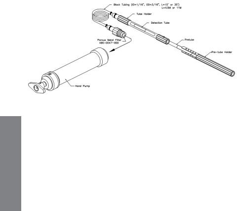
The Detection Tube Remote Sampler is designed for use with Honeywell hand pumps for gas-detection tubes and adsorption tubes. The flexible Remote
Sampler allows gases to be sampled through narrow apertures, down holes, or from other areas remotely located from the sampling pump. The sampler is available in two lengths, 15 feet (4.5 meters), p/n H-010-3009-015, and 35 feet (11 meters), p/n H-010-3009-035.
1.Installation
Refer to Figure 3.7 for installation and part descriptions. Unscrew the pump adapter nut and remove the standard rubber tube adapter from the pump. Inspect the remote sampler to ensure that the porous metal filter is in place, and screw the pump adapter nut attached to the sampler into the pump. Store the standard nut and rubber adapter in a safe place for later use.
OPERATION
www.honeywellanalytics.com |
15 |
OPERATION
2.Operation
To ensure a good seal, insert the gas detection tube into the tube holder and twist the tube while pushing in. If the tube uses a pre-tube, insert the pre-tube into the pre-tube holder and push the pre-tube into the end of the standard tube holder. Secure the pre-tube holder using the rubber buckles. Lower the extension hose to the desired position.
Figure 3-6. Installation of the remote sampling probe into the LP-1200 hand pump.
3. Correction
Caution: In order to obtain accurate readings, the following corrective procedures must be employed when using the 35-foot
(11-meter) remote sampler.
 The 35-foot (11-meter) remote sampler causes a slight delay and reduced reading because of the extra volume in the extension tubing. Increase the sample time by 30 seconds for a 2-minute tube, 20 seconds for a 1.5-minute tube, and by 15 seconds for a 1-minute tube. Then multiply the reading by 1.08 to obtain the corrected value. Corrections for the 15-foot (4.5-meter) remote sampler are unnecessary.
16 |
www.honeywellanalytics.com |

4. Routine Maintenance
a.Porous Metal Filter: The metal frit filter should be replaced when it becomes visibly dirty or if the end-of-flow indicator on the pump shows that the flow takes longer than recommended on the tube box.
b.Leak Test: If a leak is discovered with either pump, first remove the probe and check the pump for leaks. Then examine the tubing and connections for the leak source, as follows:
i.Hand Pump: Insert a sealed tube into the tube holder tightly. Pull 3 pump strokes to expel the air from inside the tubing. Pull a fourth stroke and wait for 2 minutes. Rotate the plunger dot away from the pump shaft alignment mark, and allow for the plunger to be drawn back into the pump shaft. Keep your hand on the shaft to prevent it from springing back too suddenly. If the plunger returns to within 3 mm of its original position, there are no leaks.
OPERATION
www.honeywellanalytics.com |
17 |

OPERATION
18 |
www.honeywellanalytics.com |
4. TECHNICAL INFORMATION
4.1 Gas Detection Tube Theory Of Operation
Gas detection tubes operate on a chemical reaction between the vaporphase compound and a liquid or solid detecting reagent, which is supported on an inert matrix. The most common types of reactions are the following:
•Acid-base reactions These include reactions of acidic gases like HCl and HF with bases, and reaction of alkaline vapors such as ammonia with an acid in the tube. A dye present in the tube changes color as the pH changes on exposure to the vapors.
•Reduction-oxidation(Red-ox)reactionsThese generate an oxidized or reduced compound, which has a different color. The chlorine tube uses oxidative coupling of colorless o-toluidine to form an orange azodye. White di-iodine pentoxide is reduced by CO and many organic vapors to form deep brown-colored iodine. Orange chromium (VI) is reduced by many organic compounds to form brown or green-colored Cr(III) compounds.
•Ligand-exchange reactions These generate new complexes that are more colored than the starting reagents. The most notable is the conversion of white lead acetate to brown-black lead sulfide in the
detection of H2S. In the case of phosphine, the exchange of PH3 for the chlorine ligand of HgCl2 releases HCl, which then causes a pHdependent dye-color change.
•Pre-layers or Pre-tubes These are used to condition the sample by controlling humidity, removing interferences, or transforming the analyte to another detectable compound. Examples include drying
agents in NH3 and HCl tubes, organic removal by charcoal or oxidation in selective CO tubes, and oxidation of NO to NO2 in the nitrogen oxides tube.
All Honeywell detection tubes are length-of-stain types. In these tubes, the reaction of the gas with the supported reagent is fast, compared to the transport of the bulk air sample through the tube. Therefore, all of the detected vapors are reacted within the tube. As a result, there is not a strong dependence of the readings on the rate at which the gas is sampled. However, a very high flow rate can cause some smearing to a high reading. Conversely, low flow rates are less likely to affect the stain
INFORMATION TECHNICAL
www.honeywellanalytics.com |
19 |
TECHNICAL INFORMATION
length, but can give low readings by concentrating the colored products in a shorter section of the tube. In cases of flow extremes, errors outside the standard 25% accuracy can be produced.
Honeywell tubes are calibrated using Honeywell piston hand pumps. The flow during a single pump stroke initially rises sharply and then decays exponentially (see Figure 4-1). The best accuracy is therefore obtained when the flow through the tube mimics this profile.
Figure 4-1. Piston pump internal pressure pattern. Data is offset by 2 seconds.
4.2 Explanation Of Data Sheets
The Data Sheets supplied with each box of tubes give representative information applying to all batches. The Data Sheets include:
1.Standard and extended measurement ranges, pump strokes required, gas volumes required, sampling times, and the detection limit. The standard range and strokes apply to the calibration scale printed on the tubes. The range can usually be extended to higher or lower concentrations by reducing or increasing, respectively, the number of pump strokes.
2.Correction Factors (CF) for conditions of pump stroke, temperature,
humidity, or gas type other than the standard conditions. The CF is multiplied by the observed reading to obtain the corrected concentration.
20 |
www.honeywellanalytics.com |
3. Precision. This value is determined by measuring a standard gas |
|
|
sample with at least 5 randomly chosen tubes. Precision is reported |
|
|
as the standard deviation from the average of the 5 measurements. |
|
|
Precision is typically ≤±15%. (See Section 2 for complete table.) |
|
|
4. Linearity with number of pump strokes. Multiple strokes are measured |
|
|
TECHNICAL |
||
with a gas standard with concentration at the low end of the tube. |
||
|
||
Tubes must have correlation coefficients (r2) >0.95 to be considered |
|
|
linear. |
|
|
5. Humidity. The effect on the reading as a function of humidity of the |
INFORMATION |
|
standard gas is listed. Any required Correction Factors are tabulated. |
||
|
||
6. Temperature. The effect of temperature is determined by equilibrating |
|
|
the gas sample, tube, and pump to the test temperatures, typically 0°, |
|
|
10°, 25°, and 40°C (32°, 50°, 77°, and 104°F). Any required Correction |
|
|
Factors are tabulated. If humidity has a measurable effect on the gas |
|
|
readings, the temperature tests are performed at constant relative |
|
|
humidity (not absolute humidity). Any temperature corrections should |
|
|
be multiplied by any humidity corrections to obtain true readings. |
|
|
7. Storage Life. Samples of tubes are stored for extended periods to |
|
|
evaluate their accuracy at defined time periods to determine their |
|
|
storage life. The user should store tubes in darkness at 3° to 7°C (37° |
|
|
to 45°F) to maximize their shelf life. Freezing tubes (storage below |
|
|
0°C, or 32°F) can damage some types and is not recommended. |
|
|
8. Cross-Sensitivity. Tubes are challenged with a variety of possible |
|
|
interfering gases to quantitate their relative response. Although the |
|
|
tubes are highly selective, compounds that are chemically similar to |
|
|
a target compound sometimes show a positive interference. Others |
|
|
interfere with the measurement gas without showing a response |
|
|
on their own; for example, when acidic vapors coexist with basic |
|
|
vapors. Such information is listed in a separate note or column titled |
|
|
“Interferes in Mixtures.” The user should know as much about the |
|
|
sample environment as possible in order to make sound judgments |
|
|
regarding possible interferences; otherwise inaccurate readings may |
|
|
result. In some cases, a different color or pattern of the stain can clue |
|
|
the user to the presence of an interfering compound. |
|
www.honeywellanalytics.com |
21 |
TECHNICAL INFORMATION
4.3 Humidity, Temperature, Pressure, and Matrix Effects
1. Humidity
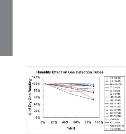
Humidity has little effect on most tubes either because the reaction is insensitive to moisture or because drying agents are added to absorb the moisture in a pre-layer (see Figure 4-2). Humidity tends to have the greatest effect on compounds that are highly water-soluble, such as acids and bases. HF (hydrofluoric acid) is a notable example that requires humidity corrections; water-adsorbing prelayers cannot be used because they tend to be reactive with HF. The humidity effect tends to be greater as the concentration range of the tube is lowered. When correcting for humidity, the CF is multiplied by the reading in addition to multiplying by any temperature correction. Any necessary Correction Factors are listed in the individual tube data sheets. Note that the relative humidity at the measurement temperature defines the correction, rather than the absolute humidity.
Figure 4-2. Effect of humidity on gas detection tube readings.
22 |
www.honeywellanalytics.com |

2. Temperature
Temperature can affect gas tube readings in at least three ways. First, as the temperature increases, the gas density decreases, causing a tendency for the reading to decrease (see pressure effects described in the next section). Second, as the temperature increases, the reaction rate increases, causing the reading to be sharper and shorter. A third, balancing effect is that adsorption is often a prerequisite for reaction. Adsorption is weaker as temperature increases, and thus the reading can become longer. The interplay of these competing effects results in some stains that are longer with increasing temperature, and others that are shorter.
Figure 4-3. Effect of temperature on gas detection tube readings.
Additional factors occur in special cases. For example, pretube or prelayer reactions are sometimes more complete at higher temperatures, causing higher readings in the measurement layer. In some cases, the color of the stain can change. In the water vapor H-10-120-20 tube, the color stain is green at room temperature and a more purple color below room temperature.
INFORMATION TECHNICAL
www.honeywellanalytics.com |
23 |

TECHNICAL INFORMATION
3. Pressure
Tubes change color in proportion to the mass of the compounds reaching the reagent (i.e, the absolute concentration). Therefore, as the pressure decreases at higher altitudes, the apparent response is reduced because there are fewer molecules per unit volume sampled. The conventional desired reading is in ppmv (parts per million by volume), which is a relative concentration, such as a mole or volume fraction (% of molecules of compound per molecules of total gas [air]), rather than an absolute concentration.
All Honeywell tubes are calibrated at 1 atmosphere (760 mm Hg) pressure at sea level.
•For tubes calibrated in absolute concentrations such as lbs./MMCF or mg/m3, no pressure corrections are needed.
•For tubes calibrated in relative concentrations (e.g., ppm), correct for pressure using one of the following equations:
Corrected reading = Observed Reading x 760 mm Hg Pressure (mm Hg)
Corrected reading = Observed Reading x 101.3 kPa
Pressure (kPa)
Corrected reading = Observed Reading x 14.7 psia
Pressure (psia)
The pressure in mm Hg can be estimated as a function of altitude using the following equation:
P (mm Hg) = 760exp(-0.1286[alt(km)]) below 2 km
Example Correction Factors are listed in the following table as a function of altitude. Weather changes may also affect the atmospheric pressure, but the necessary corrections are usually <10%.
24 |
www.honeywellanalytics.com |

Example Location |
Altitude |
Altitude |
Pressure, |
CF |
|
(km) |
(feet) |
(mm Hg) |
|
San Francisco, CA |
0 |
0 |
760 |
1.00 |
Atlanta, GA |
0.3 |
1000 |
731 |
1.04 |
Spokane, WA |
0.6 |
2000 |
703 |
1.08 |
Rapid City, SD |
0.9 |
3000 |
676 |
1.12 |
Salt Lake City, UT |
1.2 |
4000 |
650 |
1.17 |
Denver, CO |
1.5 |
5000 |
625 |
1.22 |
Colo. Spgs., CO |
1.8 |
6000 |
601 |
1.27 |
Santa Fe, NM |
2.1 |
7000 |
578 |
1.32 |
Alta, UT |
2.4 |
8000 |
555 |
1.37 |
Winter Park, CO |
2.7 |
9000 |
534 |
1.42 |
Keystone, CO |
3.0 |
10000 |
514 |
1.48 |
4. Matrix Gas
The matrix gas usually has little or no effect on the tube readings as long as the gas does not chemically react with the tube reagents or measured compound. Thus, readings in air, nitrogen, hydrogen, helium, or carbon dioxide give essentially the same results. However, the viscosity of the gas has a significant effect on the sampling time. Thus, for example, the sampling time of the CO H-10-102-18 tube is about half as long in pure hydrogen (viscosity 9.0 μPa-s) as it is in air (viscosity 18.6 μPa-s).
|
Viscosity |
Sampling Time |
Sampling Time for |
Matrix Gas |
@ 27°C |
a 90 second Tube |
|
|
(μPa-s) |
Relative to Air |
(seconds) |
Air |
18.6 |
1.00 |
90 |
n-Butane |
7.5 |
0.40 |
36 |
Propane |
8.3 |
0.45 |
40 |
Hydrogen |
9.0 |
0.48 |
44 |
Ethane |
9.5 |
0.51 |
46 |
Acetylene |
10.4 |
0.56 |
50 |
Methane |
11.2 |
0.60 |
54 |
Carbon Dioxide |
15.0 |
0.81 |
73 |
Nitrogen |
17.9 |
0.96 |
87 |
Helium |
20.0 |
1.08 |
97 |
Oxygen |
20.8 |
1.12 |
101 |
Argon |
22.9 |
1.23 |
111 |
Neon |
32.1 |
1.73 |
155 |
At a given viscosity, higher flow rates tend to give longer stains. However, this is often compensated by higher diffusion rates to the reactive surface in the less viscous gases, resulting in no significant effect on the readings.
INFORMATION TECHNICAL
www.honeywellanalytics.com |
25 |
DATA SHEETS
5. DATA SHEETS FOR GAS DETECTION TUBES
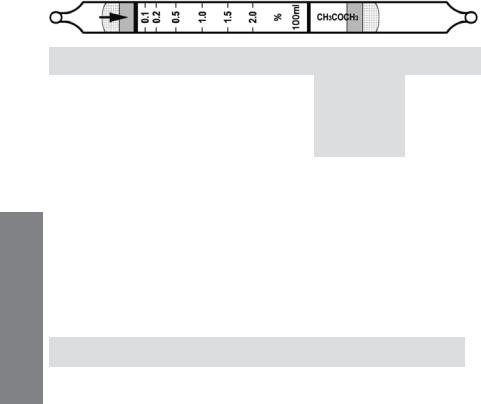
Acetone C3H6O |
|
No. H-10-111-40 |
||
|
|
|
|
|
|
|
Extended |
Standard |
Extended |
|
|
Range |
Range |
Range |
Range (ppmv) |
|
0.05 - 1% |
0.1 - 2% |
0.2 - 4% |
No. of Pump Strokes |
|
2 |
1 |
0.5 |
Sample Volume (mL) |
|
200 |
100 |
50 |
Sample Time (min) |
|
2 x 2 |
2 |
1.5 |
Correction Factor |
|
0.5 |
1 |
2 |
Precision (Relative Standard Deviation)*: ≤ ±12%
Linearity with No. of Pump Strokes: r2 = 0.992
Humidity: No effect 5 - 85% RH
Temperature Range: |
0 - 40°C (32 - 104°F) |
|||
Temp (°C/°F) |
0/32 |
10/50 |
25/77 |
40/104 |
Corr. Factor |
1.25 |
1.15 |
1.0 |
0.95 |
Storage Life: 2 years in darkness at 5 - 25°C (40 - 77°F). Refrigeration preferred. Color Change: Orange → Black
Reaction Principle: CH3COCH3 + Cr(VI) + H2SO4 → Cr(III) + Oxidation Prods.
Cross-sensitivity: |
Concentration |
Apparent |
Corr. |
Substance |
(ppmv) |
Reading* |
Factor |
Methyl ethyl ketone |
0.6% |
0.55% |
1.1 |
Methyl propyl ketone |
1.0% |
0.65% |
1.5 |
Methyl isobutyl ketone |
1.0% |
0.40% |
2.5 |
CO |
1.5% |
0 |
- |
CO2 |
1.5% |
0 |
- |
CH4 |
2.5% |
0 |
- |
NH3 |
5.0% |
1.4% brown |
3.6 |
H S |
300 |
0.5% diffuse# |
- |
2 |
1.0% |
0.85% diffuse# |
- |
Ethyl Acetate |
|||
Hexane |
0.24% |
entire tube# |
- |
Isobutylene |
0.20% |
entire tube# |
- |
Toluene |
400 |
0.3% diffuse# |
- |
* Data based on Honeywell pumps and tubes used in standard range.
#Faint black color over entire stain length. Ketones can be distinguished by their darker stains and sharp endpoints.
Other Possible Interferences: Other hydrocarbons.
26 |
www.honeywellanalytics.com |
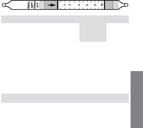
Amines RNH2 (CH3NH2) No. H-10-132-10
|
Extended |
Standard |
Extended |
|
Range |
Range |
Range |
Range (ppmv) |
0.25 - 5 |
0.5 - 10 |
1.0 - 20 |
No. of Pump Strokes |
2 |
1 |
0.5 |
Sample Volume (mL) |
200 |
100 |
50 |
Sample Time (min) |
2 x 1 |
1 |
1 |
Correction Factor |
0.5 |
1.0 |
2.0 |
Precision (Relative Standard Deviation)*: ≤ ±20% Linearity with No. of Pump Strokes: r2 = 0.997 Humidity: No effect 0 - 90% RH
Temperature Range: 0 - 40°C (32 - 104°F) @ constant 50%RH.
Temp (°C/°F) |
|
0/32 |
|
10/50 |
|
20/68 |
|
30/86 |
|
40/104 |
|
|
||
Corr. Factor |
|
1.16 |
|
1.10 |
|
1.0 |
|
0.96 |
|
0.96 |
|
|
||
Storage Life: |
1 year in darkness at 5-25°C (40-77°F). Refrigeration preferred. |
|||||||||||||
Color Change: |
Pink |
→ Yellow |
|
|
|
|
|
|
|
|
|
|||
Reaction Principle: 2RNH2 |
+ H2SO4 |
|
→ (RNH3)2SO4 |
|
|
|||||||||
|
|
|
|
|
|
|
|
|
|
|||||
Cross-sensitivity: |
|
|
|
Concentration |
|
|
Apparent |
|
Correction |
|||||
Substance |
|
|
|
|
|
(ppmv) |
|
|
Reading* |
|
Factor |
|||
Ammonia |
|
|
|
|
|
5 |
|
|
|
6.0 |
|
0.8 |
||
Methylamine |
|
|
|
|
|
10 |
|
|
|
10* |
|
1.0 |
||
Ethylamine |
|
|
|
|
|
8 |
|
|
|
7.0 |
|
1.1 |
||
Allyamine |
|
|
|
|
|
7.4 |
|
|
|
8.0 |
|
0.93 |
||
Diethylamine |
|
|
|
|
|
5 |
|
|
|
6.3 |
|
0.79 |
||
Trimethylamine |
|
|
|
|
4.5 |
|
|
|
9.8 |
|
0.46 |
|||
Triethylamine |
|
|
|
|
|
6 |
|
|
|
9.5 |
|
0.63 |
||
Methylaziridine (Propylene imine) |
|
5 |
|
|
|
6.5 |
|
0.77 |
||||||
Ethylenediamine |
|
|
|
|
7 |
|
|
|
2.0# |
|
3.5 |
|||
Ethanolamine |
|
|
|
|
|
36 |
|
|
|
4.1# |
|
8.8 |
||
Pyridine |
|
|
|
|
|
10 |
|
|
Over range† |
|
- |
|||
H2S |
|
|
|
|
|
100 |
|
|
|
0 |
|
|
||
CO |
|
|
|
|
|
500 |
|
|
|
0 |
|
|
||
Isobutylene |
|
|
|
|
|
100 |
|
|
|
0 |
|
|
||
HCl |
|
|
|
|
|
1000 |
|
|
|
0£ |
|
|
||
*Data based on Honeywell pump and tubes used in standard range. This tube is calibrated using methylamine.
# Deep purple with yellow stain at endpoint.
† Slight color change to light pink. £ Interferes in mixtures.
Other Possible Interferences: Other bases.
SHEETS DATA
www.honeywellanalytics.com |
27 |
DATA SHEETS
Ammonia NH3 |
No. H-10-100-05 |
|
|
|
|
|
|
|
|
|
|
|
|
|
|
|
|
|
|
|
|
|
|
|
|
Extended |
Standard |
Extended |
|||||
|
|
|
|
|
|
|
|
Range |
Range |
Range |
|||||
Range (ppmv) |
|
|
|
|
|
0.5 - 15 |
|
|
1 - 30 |
2 – 60 |
|||||
No. of Pump Strokes |
|
|
|
|
|
2 |
|
|
1 |
0.5 |
|||||
Sample Volume (mL) |
|
|
|
|
|
200 |
|
|
100 |
50 |
|||||
Sample Time (min) |
|
|
|
|
2 x 1.5 |
1.5 |
1 |
||||||||
Correction Factor |
|
|
|
|
|
|
0.55 |
|
|
1 |
2.4 |
||||
Precision (Relative Standard Deviation)*: ≤ ± 12% |
|
|
|
||||||||||||
Linearity with No. of Pump Strokes: r2 = 0.999 |
|
|
|
||||||||||||
Humidity: The tubes are calibrated at 50% RH @ 24 °C (75 °F) |
|
||||||||||||||
|
|
|
|
|
|
|
|
|
|
|
|
|
|
|
|
% RH |
|
< 5% |
|
10% |
|
50% |
|
80% |
|
|
95% |
|
|
||
Corr. Factor |
|
0.8 |
|
0.85 |
|
1.0 |
|
1.0 |
|
|
1.0 |
|
|
||
Temperature Range: 0 - 40°C (32 - 104°F) @ constant 50%RH |
|
||||||||||||||
|
|
|
|
|
|
|
|
|
|
|
|
||||
Temp (°C/°F) |
|
0/32 |
10/50 |
|
25/77 |
35/95 |
|
|
|
|
|
||||
Corr. Factor |
|
|
0.9 |
0.95 |
|
1.0 |
1.1 |
|
|
|
|
|
|||
Storage Life: 2 years in darkness at 5 - 25°C (40-77°F). Refrigeration preferred.
Color Change: Purple |
→ Beige |
|
||
Reaction Principle: Prelayer reduces humidity effects |
|
|||
3NH3 + H3PO4 → (NH4)3PO4 |
|
|||
|
|
|
|
|
Cross-sensitivity: |
|
Concentration |
|
Apparent |
Substance |
|
(ppmv) |
|
Reading* |
Pyridine |
|
10 |
|
15 |
Diethylamine |
|
20 |
|
18 |
Hydrazine |
|
20 |
|
2** |
Methylhydrazine |
|
20 |
|
2.3** |
CO |
|
100 |
|
0 |
CO2 |
|
20000 |
|
0# |
H2S |
|
200 |
|
0 |
Hexane |
|
100 |
|
0 |
Isobutylene |
|
100 |
|
0 |
Toluene |
|
100 |
|
0 |
* Data based on Honeywell pumps and tubes used in standard range. |
|
|
||||
** These hydrazines can be measured using 2 strokes with a CF of 5. |
|
|
||||
# 16000 ppm CO |
2 |
reduces the NH |
3 |
response by 30% in mixtures, 5000 ppm CO |
2 |
reduces |
|
|
|
|
|||
NH3 response by 10% in mixtures, and 1000 ppm CO2 has no effect. |
|
|
||||
Other Possible Interferences: Amines and other bases. |
|
|
||||
28 |
|
www.honeywellanalytics.com |
|
|
||
 Loading...