


INTRODUCTION
Dear Customer,
We thank you for having purchasedour riding mower and hope that it will fully meet all your expectations.
This manual has been compiled in order that you may get to know your machine and to be able to use it safely and efficiently.Donʼt forget that the manual forms an integral part of the machine so keep it handy so that it can be consulted at any time, and pass it on to the purchaser if you resell the machine.
Your new machine has been designed and made in line with current regulations, and is safe and reliable if used for cutting and collecting grass observing the indications given in this manual (proper usage). Using the machine in any other way or ignoring the instructions for safe usage, maintenance or repair, is considered "incorrect usage" (Chap. 5) which will invalidate the guarantee, and the manufacturer will decline all responsibility, placing the blame with the user for damage or injury to himself or others in such cases.
If you should find any slight differencesbetween the descriptionand your own machine, bear in mind that, since there are continual improvements to the product, information contained in this manual may be modified without prior warning and without the obligation to update it, although the essential safety and function characteristics will remain unaltered. In case of any doubts, do not hesitate to contact your Dealer.
After-Sales Service
This manual gives all the necessary instructions for using the machine and the basic maintenance that may be carried out by the user. For all information not contained here, contact your Dealer.
Note your machine serial number here
HOW TO READ THE MANUAL
This manual describes both mechanically and hydrostatically driven machines, as well as versions including equipment and accessories that may not be available in your area.
The symbol highlights all differences in usage and is followed by the indication of the type of drive or version to which it refers.
Some paragraphs in the manual contain information of particular importance and these are highlighted at various levels of emphasis, and signify the following:
|
|
|
|
NOTE |
or |
IMPORTANT |
These give details or further |
information on what has already been said, and are aimed at preventing |
|||
damage to the machine or causing damage. |
|||
WARNING! |
|
neself or others.Non-observance will result in the risk of injury to |
|
DANGER! |
Non-observancewill result in the risk of serious in- |
ury or death to oneself or others.
Honda France Manufacturing S.A.S.
Pôle 45 - Rue des Châtaigniers - 45140 ORMES - FRANCE
CG71505501H4
All rights reserved
|
|
|
ENGLISH |
|
ORIGINAL INSTRUCTION |
||||
OPERATORʼS MANUAL |
||||
|
||||
|
Lawn mower |
|
||
|
HF1211 |
|
||
TABLE OF CONTENTS
1. |
SAFETY .......................................................................... |
2 |
|
|
Regulations for using the machine safely |
|
|
2. |
IDENTIFICATION OF THE MACHINE AND PARTS ...... |
3 |
|
|
Explanations on how to identify the machine |
|
|
|
and its main parts |
|
|
3. |
UNPACKING AND ASSEMBLY ...................................... |
4 |
|
|
Explanations on how to remove the packing |
|
|
|
and on how to assemble separated parts |
|
|
4. |
COMMANDS AND CONTROL INSTRUMENTS ............. |
6 |
|
|
Position and functions of all the controls |
|
|
5. |
HOW TO USE THE MACHINE ....................................... |
8 |
|
|
Provides indications for working efficiently and safely |
8 |
|
|
5.1 |
Directions before starting .......................................... |
|
|
5.2 |
Starting and moving ................................................. |
9 |
|
5.3 |
Grass cutting .......................................................... |
10 |
|
5.4 |
Cleaning and storage ............................................. |
12 |
6. |
MAINTENANCE ............................................................ |
13 |
|
|
All the information for maintaining the machine |
|
|
|
in peak efficiency |
|
|
7. |
ENVIRONMENTAL PROTECTION ............................... |
19 |
|
|
It gives advice on machine use and respecting |
|
|
|
the environment |
|
|
8. |
TROUBLESHOOTING .................................................. |
19 |
|
|
A help in quickly resolving any problems |
|
|
9. |
ACCESSORIES ON REQUEST .................................... |
20 |
|
|
A description of the accessories available |
|
|
|
for particular types of work |
|
|
10. |
SPECIFICATIONS ......................................................... |
21 |
|
|
A summary of the main specifications |
|
|
|
of your machine |
|
|
|
MAJORS HONDA DISTRIBUTOR ADDRESSES ........... |
i |
|
|
“EC Declaration of Conformity” |
ii |
|
|
CONTENT OUTLINE ....................................................... |
||
1 EN

1. SAFETY
GENERAL SAFETY REGULATIONS
|
|
|
|
||
|
|
WARNING! |
|
Read carefully before using the machine. |
|
A) TRAINING |
|||||
|
|||||
1) |
Read the instructions carefully. Be familiar with the controls and the pro- |
||||
per use of the equipment. Learn how to stop the engine quickly. |
|||||
2) |
Only use the machine for the purpose for which it was made, that is, the |
||||
cutting and collection of grass. Any use not specifically indicated in the |
|||||
Operatorʼs Manual can be dangerous and result in damage to the machine, |
|||||
and will also result in the annulling of the warranty and the manufacturer |
|||||
declining all responsibility. |
|||||
3) |
Never allow children or people unfamiliar with these instructions to use |
||||
the machine. Local regulations may restrict the age of the operator. |
|||||
4) |
Never use the machine: |
||||
– |
when people, especially children, or pets are nearby. |
||||
– |
if the operator has taken medicine or substances that can affect his abili- |
||||
5) |
ty to react and concentrate. |
||||
Keep in mind that the operator or user is responsible for accidents or haz- |
|||||
ards occurring to other people or their property. |
|||||
6) |
Do not carry passengers. |
||||
7) |
The operator of a machine must carefully follow the driving instructions, |
||||
particularly: |
|
||||
– |
the need for care and concentration when using machines; |
||||
– |
that control of a machine sliding on a slope will not be regained by the ap- |
||||
|
plication of the brake. The main reasons for loss of control are: |
||||
|
– |
insufficient wheel grip; |
|||
|
– |
being driven too fast; |
|||
|
– |
inadequate braking; |
|||
|
– |
the type of machine is unsuitable for its task; |
|||
8) |
– |
lack of awareness of the effect of ground conditions, especially slopes; |
|||
The machine is equipped with a series of safety microswitches and de- |
|||||
vices which must never be removed, altered or tampered with. Removing |
|||||
these devices invalidatesthe warranty and the manufacturerdeclines any re- |
|||||
sponsability. |
|
||||
B) PREPARATION |
|
||||
1) |
While mowing, always wear substantial footwear and long trousers. Do |
||||
not operate the equipment when barefoot or wearing open sandals. |
|||||
2) |
Thoroughly inspect the area where the equipment is to be used and re- |
||||
move all objects which may be thrown by the machine (stones, sticks, metal |
|||||
wire, bones, etc.) |
|
||||
3) |
WARNING: DANGER! - Engine fuel is highly flammable: |
||||
– |
store fuel in containers specifically designed for this purpose; |
||||
– refuel using a funnel and outdoors only. Do not smoke while refuelling or |
|||||
– |
whenever handling the fuel; |
||||
add fuel before starting the engine. Never remove the cap of the fuel tank |
|||||
– |
or add fuel while the engine is running or when the engine is hot; |
||||
if fuel is spilled, do not attempt to start the engine but move the machine |
|||||
|
away from the area of spillage and avoid creating any source of ignition |
||||
– |
until the fuel has evaporated and the fumes dispersed; |
||||
replace caps of all fuel tanks and containers securely. |
|||||
4) |
Replace faulty silencers. |
||||
5) |
Before using, always carry out a visual inspection,particularlyof the blade, |
||||
seeing that the screws and cutter assembly are not worn or damaged. Re- |
|||||
place a worn or damaged blade and screws as a set to preserve balance. |
|||||
6) |
Before mowing, attach the discharge opening guards (grass-catcher or |
||||
stone-guard). |
|
||||
C) OPERATION
1)Do not operate the engine in a confined space where dangerous carbon monoxide fumes can collect.
2)Mow only in daylight or good artificial light.
3)Avoid operating the equipment in wet grass, where feasible.
4)Before starting the engine, disengage the blade, shift the gear lever
( mechanicaldrive models) or the speed change lever ( hydrostaticdrive models) into neutral and engage the parking brake.
5)Do not use on slopes of more than 10° (17%).
6)Rememberthere is no such thing as a “safe” slope. Travelon grass slopes
EN 2
requires particular care. To guard against overturning: |
|
||||||||
– do not stop or start or change directionsuddenlywhen on slopes,and keep |
|||||||||
|
to a moderate speed; |
|
|
|
|
|
|
mechanical |
|
– |
engage clutch slowly, always keep the machine in gear ( |
|
|
|
|||||
|
|
|
|||||||
|
drive models) or engage the speed change lever slowly both for forward |
||||||||
|
and reverse movement ( |
|
hydrostatic drive models), especially when |
||||||
|
|
||||||||
– |
travelling downhill; |
|
|
|
|
|
|
|
|
reduce speed before taking a slope and during tight turns; |
|
||||||||
– |
stay alert for humps and hollows and other hidden hazards; |
|
|||||||
– |
never mow across the face of the slope. |
|
|||||||
7) Stop the blade rotating and put the cutting deck into the highest posi- |
|||||||||
tion before crossing surfaces other than grass. |
|
||||||||
8) |
Never use the machine to cut grass if the guards are defective, or with- |
||||||||
out the stone-guard and/or grass-catcher in place. |
|
||||||||
9) |
Do not change the engine governor settings or overspeed the engine. |
||||||||
10) Before leaving the operatorʼs position: |
|
||||||||
– |
disengage the blade; |
mechanical drive models) or make sure that the |
|||||||
– |
change into neutral ( |
|
|||||||
|
|||||||||
|
|
|
|
|
|
|
|
hydrostatic |
|
|
speed change lever has returned to the neutral position ( |
|
|
||||||
|
|
|
|||||||
– |
drive models) and engage the parking brake; |
|
|||||||
stop the engine and remove the key. |
|
||||||||
11) Disengage the blade, stop the engine and remove key: |
|
||||||||
– |
before carrying out any work beneath the cutting deck or unclogging the |
||||||||
– |
collector channel; |
|
|
|
|
|
|
|
|
before checking, cleaning or working on machine; |
|
||||||||
– |
after striking a foreign object. Inspect the machine for damage and make |
||||||||
|
repairs before restarting and operating the machine; |
|
|||||||
– if the machine starts to vibrate abnormally (immediatelycheck and remove |
|||||||||
|
the cause of the vibration). |
|
|
|
|
|
|||
12) Disengage the blade when transporting or not in use. Disengage the |
|||||||||
blade and wait for it to stop before emptying the grass-catcher. |
|
||||||||
13) Stop the engine and disengage the blade: |
|
||||||||
– |
before refuelling; |
|
|
|
|
|
|
|
|
– |
every time the grass-catcher is removed or replaced. |
|
|||||||
14) Reduce the throttle setting before stopping the engine and turn the fuel off at the conclusion of mowing, following the instructions in the manual. 15) Do not put hands or feet near or under rotating parts. Keep clear of the discharge opening at all times.
16) The usage of accessories different from those recommended by Honda may cause damage to the machine that is not covered by the warranty.
D) MAINTENANCE AND STORAGE
1)Keep all nuts, bolts and screws tight to be sure the equipment is in safe working condition. Regular maintenance is essential for safety and for maintaining performance levels.
2)Never store the equipment with fuel in the tank inside a building where fumes may reach a flame or a spark or a source of extreme heat.
3)Allow the engine to cool before storing in an enclosed space.
4)Toreduce the fire hazard, keep the engine, exhaust silencer,battery compartment and fuel storage area free of grass, leaves, or excessive grease.
Always empty the grass-catcher and do not leave garden rubbish containers inside a room.
5)Frequentlycheck the stone-guard,the grass-catcherand the air intake grill for wear and deterioration. Replace if damaged.
6)For reasons of safety, do not use equipment with worn or damaged parts. Parts are to be replaced and not repaired. Use genuine spare parts (the blade should always bear the symbol ). Parts which are not of an equivalent quality can damage the equipment and may adversely affect your safety.
7)If the fuel tank has to be drained, this should be done outdoors and when the engine is cool.
8)Wear strong work gloves when removing and reassembling the blade.
9)Check the bladeʼs balance after sharpening.
10)When the machine is to be parked, stored or left unattended, lower the cutting deck.
11)The ignition key must never be left inserted in the machine, or where children or persons not familiar to the machine may reach it. Before any maintenance or repair, remove the ignition key.
E) TRANSPORTING
1) If the machine is transported on a truck or trailer, lower the cutting deck, engage the parking brake and fasten the machine securely with ropes, cables or chains to the hauling device.
SAFETY DECALS
Yourmachine must be used with care. Therefore, decals have been placed on the machine, to remind you pictorially of the main precautions to take during use. These decals are to be considered an integral part of the machine.
If a decal should fall off or become illegible, contact your retailer to replace it. Their meaning is explained below.
1 |
2 |
3 |
4 |
5 |
6 |
1 |
= Warning: Read Operatorʼs Manual before operating this machine. |
||
2 |
= Warning: Disconnect the ignition key and read the instructions before |
||
3 |
|
carrying out any repair or maintenance work. |
|
= Danger! Ejected objects: Do not operate without either stone-guard or |
|||
4 |
|
grass-catcher in place. |
|
= Danger! Ejected objects: Keep bystanders away. |
|||
5 |
= Danger! Machine rollover: Do not use this machine on slopes greater |
||
6 |
|
then 10°. |
|
= Danger! Dismemberment: Make sure that children stay clear of the |
|||
|
|
|
machine all the time when engine is running. |
|
|
7 = Risk of being cut. Blade in movement. Do |
|
7 |
|||
|
|
|
not insert hands or feet inside the blade |
|
|
|
housing. |
|
|
8 = Avoid injury from getting caught in belt: |
|
8 |
|||
|
|
|
Do not operate the machine without shields |
|
|
|
in place. Stay clear of belts. |
9 |
9 = Warning! Do not manipulate the microswitch |
|
10
 11
11
12
10 = Warning: Read the owner's manual before using the mower.
11 = Warning: The engine emits toxic carbon monoxide. Do not run in an enclosed area.
12 = Warning! Petrol is highly flammable. Stop the engine before refueling.
|
|
|
|
|
|
|
|
|
|
13 |
|
|
|
|
|
|
13 = Warning: he muffler becomes very hot dur- |
|
|
|
|
|
|
|
||
|
|
|
|
|
|
|
|
ing operationand remains hot for a while af- |
|
|
|
|
|
|
|
|
ter stopping the engine. |
|
|
|
|
|
|
|
|
14 = This is a recyclable product. It contains |
|
|
|
|
|
|
|
||
14 |
|
|
|
|
|
|
||
|
|
|
|
|
|
|||
|
|
|
|
|
|
|
|
lead. Do not discard it in the environment |
|
|
|
|
|
|
|
|
|
|
|
|
|
|
|
|
|
and dispose of in compliance with the laws |
|
|
|
|
|
|
|
|
in force. |
2.IDENTIFICATION OF THE MACHINE
AND PARTS
IDENTIFICATION OF THE MACHINE
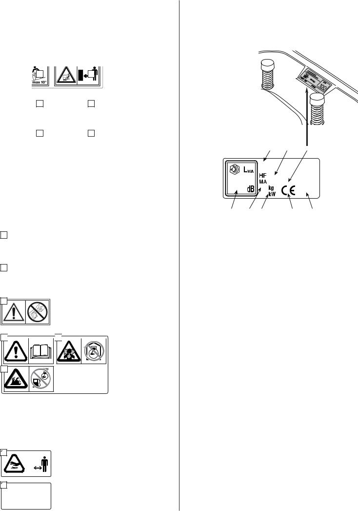
The plate located under the driverʼs seat has the essential data and serial number of each machine
(5).
This number must be quoted when you require technical assistance or spare parts.
7 |
4 |
5 |
1 |
6 |
8 |
2 |
3 |
1.Acoustic power level according to directives
2.2000/14/EC, 2005/88/EC
Conformity mark according to directives
3.2006/42/EC, 2005/88/EC, 2004/108/EC
4.Year of manufacture
5.Type of machine
6.Serial number
7.Weight in kgs
Name and adress of manufacturer are written in the "EC Declaration of Conformity" CONTENT OUTLINE
8.in this Owner's Manual. Engine nominal power
3 EN
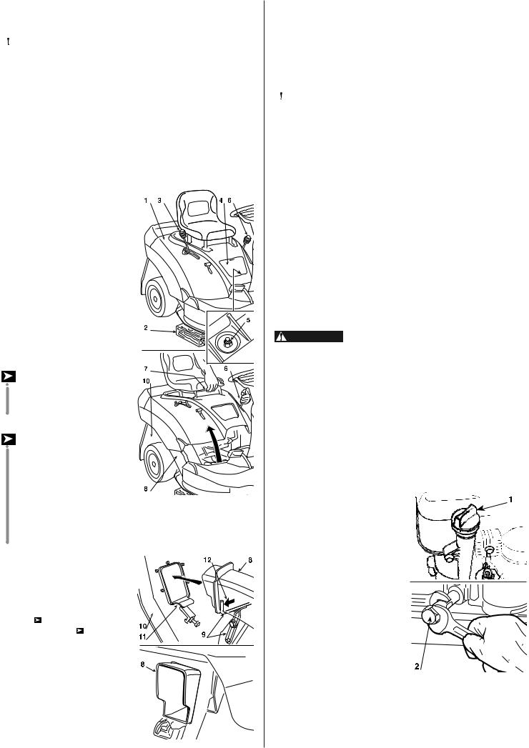
IDENTIFICATION OF MAIN COMPONENTS
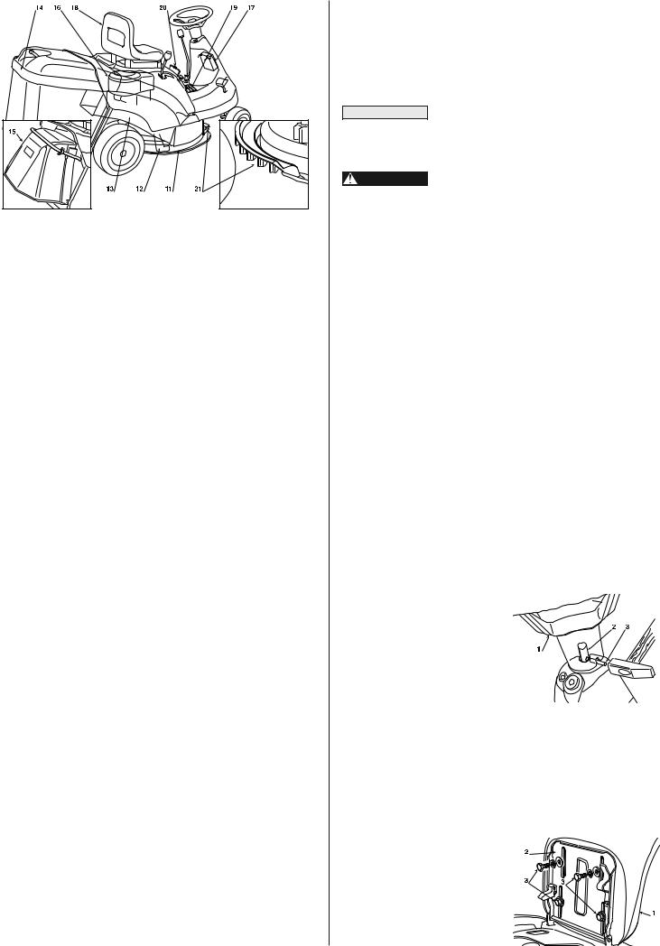
Various main components can be seen on the machine, and these have the following functions:
11.Cutting deck: this is the guard enclosing the rotating blade.
12.Blade: this is what cuts the grass. The wings at the ends help convey the cut grass towards the collector channel.
13.Collector channel: this is the part connecting the cutting deck to the grass-catcher.
14.Grass-catcher: as well as collecting the grass cuttings, this is also a safety element in that it stops any objects drawn up by the blade from being thrown outside of the machine.
15.Stone-guard or deflector: this can be fitted in place of the grass-catcher and prevents objects drawn up by the blade from being thrown outside of the machine.
16.Engine: this moves the blade and drives the wheels. It is fully described in a specific booklet.
17.Battery: provides the energy for starting the engine. It is fully described in a specific booklet.
18.Driver seat: this is where the machine operator sits. It has a sensor for detecting the presence of the operator which is a safety device.
19.Decals for regulations and safety: give reminders on the main provisions for working safely, each of which is explained in chapter 1.
20.Access hatch: gives easy access to the spark plug and the fixing nut for the engine cover.
21.Air intake grill: helps air to flow inside the cutting deck and prevents objects from being thrown out at the front.
EN 4
3. UNPACKING AND ASSEMBLY
For storage and transport reasons, some components of the machine are not directly installed in the factory, but have to be assembled after their removal from the packing. Final assembly is carried out by following these simple instructions.
IMPORTANT For transport reasons the machine is supplied without engine oil or fuel. Before starting up the engine, fill with oil and fuel following the instructions given in the engine booklet.
WARNING! Unpacking and completing the assembly should be done on a flat and stable surface, with enough space for machine handling and its packaging, always making use of suitable equipment.
UNPACKING
When unpacking the machine, take care to gather all individual parts and fittings, and do not damage the cutting deck when taking the machine off the base pallet.
The standard packing contents:
–the machine;
–steering wheel;
–seat;
–grass-catcher components;
–an envelope containing the instruction manual, documents and the nuts and bolts with two starter keys, a pin for blocking the steering wheel and a spare 6.3 Ampere fuse.
Disposal of the packaging should be done in accordance with the local regulations in force.
FITTING THE STEERING WHEEL
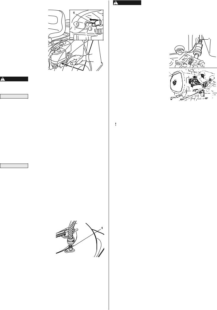
Put the machine on a flat surface and straighten up the front wheels. Fit the steering wheel (1) onto the protruding shaft (2) with the spokes directed towards the seat.
Line up the hole in the steering wheel hub with the hole in the
shaft and insert the pin supplied
(3).
Push the pin in using a hammer, ensuring that it comes completely through to the opposite side.
|
|
NOTE |
To avoid damaging the steering wheel with the |
hammer, use an awl of the same size as the pin to push it in the |
|
last part. |
|
FITTING THE SEAT
Fit the seat (1) onto the plate (2) using the screws (3).
CONNECTING THE BATTERY
The battery (1) is situated in a compartment under the steering wheel and is reached by removing the plastic cover (2) held on by two screws (3).
Insert this frame into the canvas cover, ensuring that it is correctly positioned along the base perimeter.
Hook all the plastic profiles to the frame tubes with the help of a screwdriver (7).


 7
7
CLAK
Connect the two red cables
(4) to the positive terminal
(+) and the two black cables (5) to the negative terminal (–) using the supplied screws and following the illustrated sequence.
Recharge the battery according to the manufacturer's instructions.
IMPORTANT To prevent the safety device in the electronics card from cutting in, never start the engine until the battery is fully charged!
WARNING! Follow the battery manufacturer's instrucions regarding safe handling and disposal.
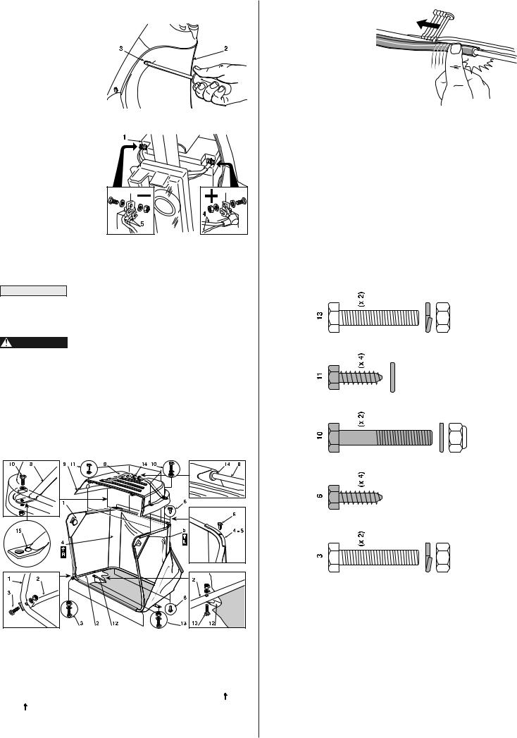
FITTING THE GRASS-CATCHER
First of all assemble the frame, joining the upper part (1), including the opening, to the lower part (2), using the supplied nuts and screws (3) and following the indicated sequence.
Position the angle supports(4) and (5), respecting the right (R ) and left (L ) sides, and attach them to the frame using the four self-tapping screws (6).
Insert the handle (8) with the grommets (14) into the holes of the can- vas (9) making sure that the end with the lump (15) is on the right. Attach this to the frame using the screws (10), following the indicated sequence, and complete the assembly screwing the four front and rear self-threading screws (11).
Position the grommets (14) in their respective holes in the canvas
(9).
Lastly, fit the stiffening bar (12) on the outside of the frame base, keeping the flat part towards the canvas and using the nuts and screws supplied (13) in the sequence indicated.
5 EN
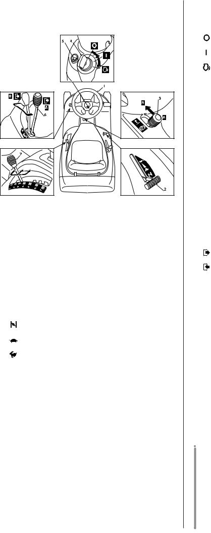
4.COMMANDS AND CONTROL
INSTRUMENTS
1.STEERING WHEEL
Turns the front wheels.
2.ACCELERATOR LEVER
Regulates the engine's r.p.m. The positions are indicated on a plate showing the following symbols:
Position «CHOKE» |
for starting up |
Position «SLOW» |
for minimum engine speed |
Position «FAST» |
for maximum engine speed |
When moving from one area to another, put the lever in a position between «SLOW» and «FAST»When cutting, go to the «FAST»position.
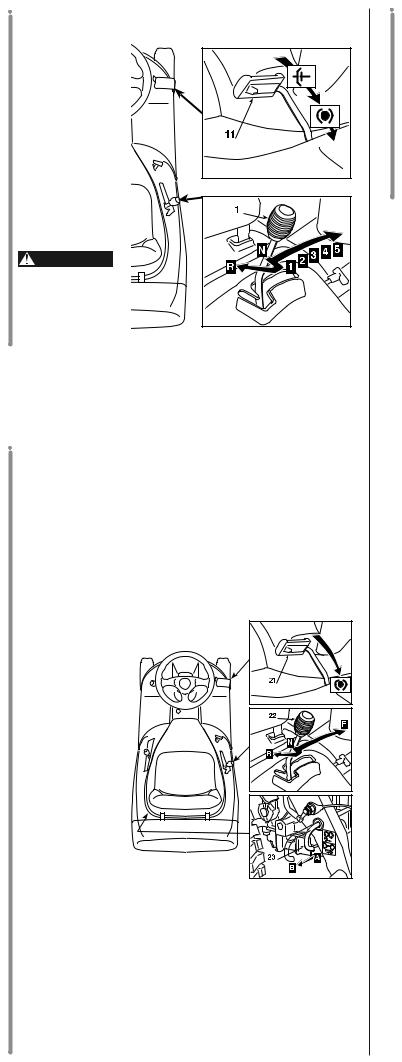
3. PARKING BRAKE LEVER
This lever is to stop the machine from moving when it has been parked, and must always be engaged before leaving the machine.
The brake is engaged by fully pressing the pedal (11 - 21) and moving the lever to position «A». When you take your foot off the pedal it will be blocked by the lever in the down position.
To disengage the parking brake, press the pedal again so that the lever returns to position «B».
EN 6
4. KEY IGNITION SWITCH
This key operated control has three positions:
«OFF» |
means everything is switched off |
«ON» |
activates all parts |
«START» |
engages the starter motor. On being |
|
released, the key will automatically |
|
return to «ON» from this position. |
5. PILOT LAMP AND SIGNAL
This light comes on when the key (4) is in the «ON» position and remains constantly lit while the machine is operating.
When it starts flashing this means that the engine is being prevented from starting (see 5.3).
The audible warning indicates that the grass-catcher is full (see 5.3).
6. BLADE ENGAGEMENT AND BRAKE LEVER
This lever has two positions, as shown on the label:
Position «A» = BLADE DISENGAGED
Position «B» = BLADE ENGAGED
If the blade is engaged when safety conditions have not been complied with, the engine shuts down (see 5.3).
On disengaging the blade (Pos. «A»), a brake is simultaneously activated which stops it rotating in five seconds.
7. CUTTING HEIGHT ADJUSTING LEVER
There are seven positions for this lever, shown as «1» to «7» on the label, which correspond to various heights of between 3 and 8 cm.
To go from one height to another, move the lever sideways and put into one of the seven notches.
 For mechanical drive models:
11. Clutch / brake pedal
This pedal has a double function - during the first part of its travel it acts as a clutch, engaging and disengaging drive to the wheels, and in the second part it acts as a brake on the rear wheels.
|
|
NOTE |
When the machine is in movement, keep your |
foot off the pedal. |
|
12. Speed change lever
This lever has seven positions for the 5 forward speeds, the neutral position «N», and reverse «R». To go from one speed to another, press the pedal (11) about half way and move the lever as per the indications on the label.
WARNING!
Reverse must only be engaged when the machine is stopped.
 For hydrostatic drive models:
21. Brake pedal
In hydrostatically driven models this pedal is solely for braking and works on the rear wheels.
22. Speed change lever
This lever engages drive to the wheels and changes the machineʼs forward and reverse speed. The machineʼs forward speed gradually increases by moving the lever towards «F». Reverse is engaged by moving the lever to «R».
When the brake pedal (21) is pressed
the lever automatically returns to the «N» (neutral) position.
It can also be moved there manually even without pressing the |
|
brake. |
|
|
|
IMPORTANT |
When the parking brake (3) is engaged the |
speed change lever is locked in the «N» position and cannot |
|
be moved until the parking brake and the pedal have been re- |
|
leased. |
|
23. Lever to release the hydrostatic drive
Position |
«A» |
= |
Drive engaged: for all operating conditions, |
Position |
«B» |
= |
when moving and during cutting; |
Drive released: considerably reduces |
|||
|
|
|
the effort required for moving the machine |
|
|
|
manually, when the engine is not running. |
|
|
IMPORTANT |
When the parking brake (3) is engaged the |
speed change lever is locked in the «N» position and cannot be moved until the parking brake and the pedal have been released.
7 EN
5. HOW TO USE
SAFETY RECOMMENDATIONS
|
The machine must only be used for the pur- |
DANGER! |
|
pose for which it was designed (cutting and collection of |
|
grass). |
|
Using the machine in any other way is considered "improper |
|
use" which will invalidate the warranty, relieve the manufac- |
|
turer from all liabilities, and the user will consequently be li- |
|
able for all and any damage or injury to himself or others. |
|
Examples of improper use may include, but are not limited to: |
|
– transport people, children or animals on the machine or on |
|
a trailer; |
|
– tow or push loads; |
|
– use of the machine for moving over unstable, slippery, |
|
icy, stony, rough, marshy ground and puddles that do not |
|
allow for evaluation of the consistency of the ground; |
|
– use of the machine for leaf or debris collection; |
|
– use of the blades on surfaces other than grass. |
|
DANGER! |
Do not tamper with or remove the safety de- |
ices fitted to the machine. REMEMBER THAT THE USER IS ALWAYS RESPONSIBLE FOR DAMAGE AND INJURIES TO OTHERS.
Before using the machine:
– read the general safety regulations (Chap. 1), paying particular attention to driving and cutting on slopes;
– carefully read the instructions for use, become familiar with the controls and on how to quickly stop the blades and engine.
– never put your hands or feet next to or beneath the rotating parts and always keep away from the discharge opening.
Do not use the machine when in a precarious state of health or under the effect of medicines or other substances that can reduce your reflex actions and your ability to concentrate.
It is the user's responsibility to assess the potentialrisk of the area where work is to be carried out, as well as to take all the necessary steps to ensure his own safety and that of others, particularly on slopes or rough, slippery and unstable ground. Do not leave the machine stopped in high grass with the engine running in order to avoid the risk of starting a fire.
|
|
This machine must not be used on slopes |
WARNING! |
|
|
greater than |
10° (17%). |
|
|
|
|
IMPORTANT |
|
All the references relating to the positions of |
controls are those described in chapter 4.
5.1 DIRECTIONS BEFORE STARTING SEAT ADJUSTMENT
The seat is held by four screws
(1) which have to be loosened for changing the position of the seat which is done by sliding it along
the slots in the base.
When you have got in a comfortable position, fully tighten the four
screws.
EN 8
OIL LEVEL AND REFUELLING
|
|
IMPORTANT |
Engine oil is a major factor affecting engine per- |
formance and service life. Non-detergent oils and vegetable oils are not recommended. Be sure to check the engine on a level surface with the engine stopped.
Use Honda 4-stroke, or an equivalent high detergent, premium quality motor oil certified to meet or exceed U.S. automobile manufacturerʼs requirements for service classification SG, SF.
Motor oils classified SG, SF will show this designation on the container.
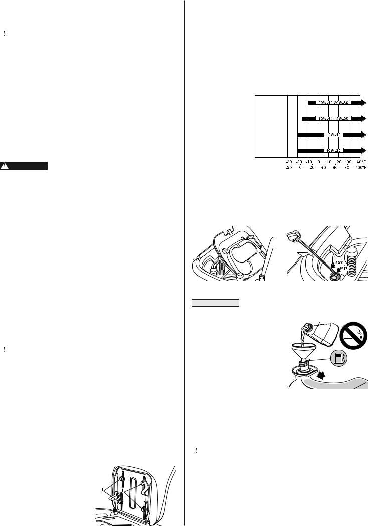
SAE 10W-30 is recommended for general, all temperature use. If single viscosity oil is used, select the appropriate viscosity for the average temperature in your
area.
Toreach the oil level dipstick, lift up the seat and open the hatchway beneath.
With engine stopped, check its oil level which must be between the MIN and MAX marks on the dipstick when not screwed in. Do not forget to screw down the dipstick when replacing it.
IMPORTANT |
|
• Never use a gas-oil mixture. |
|
• Only use unleaded petrol 95 |
|
or 98. |
|
• Do not let dirt, clippings,etc. |
|
get into the tank. |
|
• Do not use dirty or contami- |
|
nated fuel (water, durst, ...), or |
|
fuel which is too old. The qua- |
|
lity of unleaded petrol deterio- |
MAX |
rates with time. Do not keep |
|
fuel for more than one month. |
|
Refuel using a funnel, but be sure to not exceed the max level shown in the figure.
The tank's capacity is about 3.6 litres.
|
Refuelling should be carried out in an open |
DANGER! |
|
or well ventilated area with engine stopped. Always remem- |
|
ber that petrol fumes are inflammable. DO NOT TAKE |
|
FLAMES TO THE TANK MOUTH TO VERIFY ITS CONTENTS |
|
AND DO NOT SMOKE WHEN REFUELLING. |
|
|
|
IMPORTANT |
Do not drip petrol onto the plastic parts to avoid |
ruining them. In the event of accidental leaks, rinse immediately |
|
with water. |
|
• Fuel containing alcohol
IMPORTANT If you intend to use fuel with alcohol, ensure that
its octane number is at least as high as that recommended by Honda (86). There are two types of fuel/alcohol mixtures: one con- tains ethanol and the other methanol.
Do not use mixtures containing more than 10% ethanol, or fuel containing methanol (methyl or wood alcohol), which do not contain cosolvents, or corrosion inhibitors for methanol.
In the case of a mixture containing methanol with addition of cosolvents and corrosion inhibitors, limit the proportion to 5% of methanol.
The guarantee does not cover damage caused to the fuel system or engine performance problems resulting from the use of fuel containing alcohol. Honda does not give its approval to the use of fuels containing methyl alcohol since their suitability is not yet proven.
TYRE PRESSURE
Having the correct tyre pressure is essential for keeping the cutting deck horizontal and thus achieving uniform mowing.
Unscrew the valve protection cap and connect the valves to a compressed air line with a gauge.
Pressures are:
FRONT
REAR
FITTING THE PROTECTION AT THE EXIT (GRASS-CATCHER OR STONE-GUARD)
WARNING! Never use the mahine without having fitted the exit
protection!
WARNING! There is a microwitch which stops the engine or prevents starting when the blade is engaged if either the grass-catcher or stone-guard is not in position. IT IS VERY DANGEROUS TO TAMPER WITH OR LIMIT THE EFFEC-
TIVENESS OF THIS DEVICE!
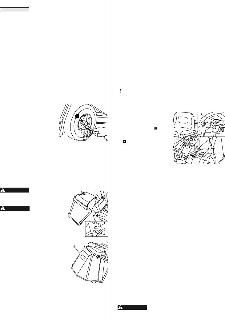
Lift the removable cover (1) and hook on the grass-catcher by inserting the two pivots (2) into the slots on the two supports
(3).
If you want to work without using the grasscatcher, a stone-guard kit (4) is available on request which is fitted as shown in the figure.
CHECKING THE SAFETY SYSTEMS
Every time before using, check that the safety systems are working properly. To do so, simulate the various situations of usage shown in the table on page 11, making sure that the correct result is a- chieved for each situation.
CHECKING THE BRAKING SYSTEM
Make sure that the machineʼs braking capacity is adequate for the conditions of usage. Avoid starting the machine if you have doubts on the brake efficiency. If necessary, adjust the brake and if you still have doubts on its efficiency, consult your dealer.
BLADE CHECK
Check that the blade is sharpened properly and firmly fixed to the hub. A badly sharpened blade pulls at the grass and causes the lawn to turn yellow.
5.2 STARTING AND MOVING
STARTING |
|
|
All starting operations have to be effected in |
DANGER! |
|
n open or well ventilated area! ALWAYSREMEMBER THAT |
|
EXHAUST GASES ARE TOXIC! |
|
Before starting the engine: |
|||
– open the fuel stop-cock (1), |
|||
|
which is reached through the |
||
– |
around the right back wheel; |
||
put the gear lever ( |
for me- |
||
|
chanical drive models) or the |
||
|
speed change lever |
pedal |
|
|
( |
for hydrostatic drive mod- |
|
|
els) into neutral («N»); |
||
– on slopes, engage the park- |
|||
|
ing brake; |
|
|
– put |
the blade engagement |
||
|
lever into the disengage posi- |
||
|
tion («A»). |
|
|
Afterwards: |
|
||
– |
put the accelerator lever to «CHOKE», as shown on the label, if |
||
|
the engine is cold. If the engine is already warm, put the lever be- |
||
– |
tween «SLOW» and «FAST»; |
||
put in the key and turn to «ON» to make electrical contact, then |
|||
|
turn to «START» to start the engine. Release once the engine has |
||
|
started. |
|
|
When the engine is running, put the accelerator into the «SLOW» |
||
position. |
|
|
|
|
|
|
NOTE |
Should you have difficulties in starting do not |
continue to use the starter motor for a long time as this can run |
||
down the battery or flood the engine. Turn the key to the «OFF» |
||
position, wait for a few seconds and then repeat the operation. If |
||
the malfunction continues, refer to chapter «8» of this manual. |
||
|
|
|
IMPORTANT |
Always bear in mind that the safety devices pre- |
|
vent the engine from starting when: |
||
– |
the blade is engaged; |
|
– |
the transmission is not in neutral («N»). |
|
– |
the operator is absent with the parking brake disengaged. |
|
While trying to start the engine in one of the above situations, the pilot lamp will start blinking.
MOVING WITHOUT MOWING
WARNING! The machine has not been approved for use on public roads. It has to be used (as indicated by the highway code) in private areas closed to traffic.
9 EN
|
|
|
|
NOTE |
When moving the machine, the blade must be |
disengaged and the cutting deck put at its highest position (posi- |
||
tion «7»). |
|
|
|
For mechanical drive models: |
|
|
||
Put the accelerator control between the «SLOW» and «FAST» positions, and the gear change lever in the 1st speed position.
Keep the pedal pressed down and disengage the parking brake. Slowly release the pedal which will turn from «brake» to «clutch», thus operating the rear wheels.
The pedal has to be released gradually as a sudden engagement may cause tipping up and loss of control of the vehicle.
The pedal must be moved in a progressive manner without hesitation in order to prevent the belt slipping too much and thus overheating.
Gradually reach the desired operatingspeed using the accelerator and gear lever. Tochange the gear speed the clutch must be used pushing the pedal down half way.
 For hydrostatic drive models:
Put the accelerator control between the «SLOW» and «FAST» positions. Press the brake pedal to disengage the parking brake and release the pedal.
Move the speed change lever in the «F» direction and go to the required speed by using the lever and the accelerator.
The lever must be moved gradually as a sudden engagement of drive to the wheels may cause tipping and loss of control of the machine.
BRAKING
 For mechanical drive models:
Tobrake, first reduce the speed on the accelerator to avoid overloading the brake assembly and then push the pedal down fully.
 For hydrostatic drive models:
To brake, press the brake pedal which will simultaneously make the speed change lever return to the «N» position.
REVERSE
 For mechanical drive models:
The machine MUST be stopped before reverse can be engaged. Push down the pedal until the machine stops and then insert reverse by moving the lever sideways and putting it into position «R». Gradually release the pedal to engage the clutch and then begin moving in reverse.
 For hydrostatic drive models:
The machine MUST be stopped before reverse can be engaged. When the machineis stopped,start the reversemovementby putting the speed change lever in the «R» direction.
EN 10
5.3 GRASS CUTTING
ENGAGING THE BLADE AND FORWARD MOVEMENT
When you have reached the area to be mowed,
– put the accelerator into the «FAST» position;
– engage the blade by putting the lever into position «B»;
– to begin moving, operate the speed regulation controls taking care to release the pedal with caution as already described.
Engage the blade with the cutting deck in the highest position, and |
||||
then gradually lower to the height required. To achieve good col- |
||||
lection and even cutting of the grass, choose a forward speed to suit |
||||
the quantity of grass to be cut (height and density) and the lawn's |
||||
humidity, in line with the following indications ( |
|
for mechanical |
||
|
||||
drive models): |
|
|
|
|
– High and dense grass - wet lawn |
1st speed |
|||
– Average condition grass |
2nd |
- 3rd speed |
||
– Low grass - dry lawn |
4th speed |
|||
|
|
|||
NOTE |
The fifth gear is solely for moving from one area |
|||
to another on horizontal surfaces |
|
|
|
|
 For hydrostatic drive models
The speed has to be adapted to the condition of the grass in a gradual and progressive way by moving the speed change lever.
A lower speed should always be selected if you note a reduction in engine speed, since a forward speed that is too fast will not cut the grass well.
Disengage the blade and put the cutting deck in the highest position whenever you need to get past an obstacle.
CUTTING HEIGHT ADJUSTMENT
The height is adjusted by moving the lever with 7 height positions.
HOW TO OBTAIN A GOOD CUT
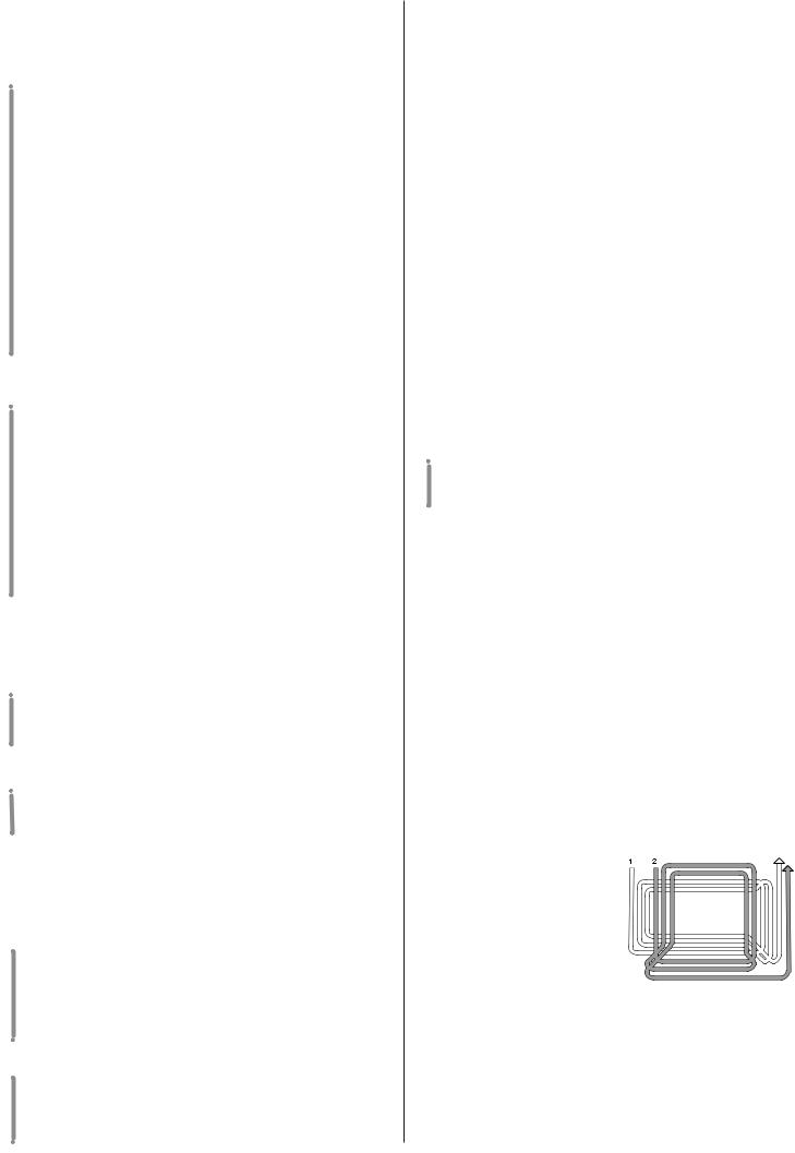
1.The lawn's appearance will be best if you cut in alternate directions, always at the same
2.height.
If the collector system blocks up you should reduce the forward speed as it could be too high for the lawn conditions.
If this does not solve the problem, it is probably due to un-
sharpened cutting edges or the wings on the blade having be-
3.come deformed (see chapter 8).
If the grass is very tall it should be mowed twice - once at the maximum cutting height, and perhaps reducing the cutting width,
4.followed by a second cut at the required height.
Be very careful when mowing near bushes or kerbs which could alter the horizontalposition of the cutting deck or damage its edge or the blade.
SLOPES |
|
|
|
Complying with the slo- |
RIGHT! |
||
pe limits already men- |
|||
tioned, lawns on a slope |
|
||
have to mowed moving |
ONG! |
||
up and down and never |
|||
across them, taking gre- |
|||
at care when changing |
R |
||
W |
|||
direction that |
the first |
|
|
wheels do not hit obsta- |
|
||
cles (such |
as |
stones, |
|
branches, |
roots, etc.), |
|
|
that may cause the machine to slide sideways, roll over or otherwise |
|||
cause loss of control. |
|
||
DANGER! |
REDUCE SPEED BEFORE ANY CHANGE OF |
||
DIRECTION ON SLOPES and always engage the parking brake before leaving the machine stopped and unattended.
WARNING! Take care when beginning forward movement on sloping ground to prevent the risk of tipping up. Reduce the forward speed before going on a slope, particularly downhill.
 For mechanical drive models:
DANGER! Never ride the machine on slopes in neural gear or with the clutch out! Always engage a low gear before leaving the machine stopped and unattended.
 For hydrostatic drive models:
Move on slopes with the speed change lever in the lowest forward speed to take advantage of the hydrostatic unit's braking effect.
DANGER! |
Never use reverse for reducing speed go- |
ng downhill. Control of the machine could be lost, par- |
|
ticularly on slippery surfaces. |
|
EMPTYING THE GRASS-CATCHER |
|
NOTE |
This operation |
can only be done with the blade |
|
disengaged, otherwise the engine |
|
stops. |
|
When the grass-catcher is full an |
|
audible warning is given. STOP |
|
FORWARD MOVEMENT, in order |
|
not to block the collector channel, |
|
and disengage the blade which will |
|
stop the audible signal. |
|
Empty the grass-catcher by lifting it |
|
using the handle. |
|
NOTE |
At times the audible warning may be heard on |
engaging the blade even when the grass-catcher has been emp- |
|
tied. This is due to grass cuttings left on the sensor of the micro- |
|
switch. To stop the signal, either remove the remaining grass or |
|
disengage the blade and then immediately engage it again. |
|
EMPTYING THE COLLECTOR CHANNEL
Cutting very tall or wet grass, particularly at too high a speed, can cause the collector channel to become blocked. Should this happen, it will be necessary to:
– stop forward movement, disengage the blade and stop the engine;
– take off the grass-catcher or stone-guard;
– remove the accumulated cuttings going in through the exit of the collector channel.
|
This must only be done when the engine is |
|
WARNING! |
||
topped. |
||
|
SUMMARY OF THE MAIN CONDITIONS
WHEREBY THE SAFETY DEVICES PERMIT OR STOP WORK
The safety devices work in two ways:
–by preventing the engine from starting if all the safety requirements have not been met;
–stopping the engine if even just one of the safety requirements is lacking.
To start the engine it will be necessary that:
–the transmission is in “neutral”;
–the blade is not engaged;
–the operator is seated or the parking brake is engaged. The engine stops when:
–the operator leaves his seat when the blades are engaged;
–the operator leaves his seat when the transmission is not in “neutral”;
–the operator leaves his seat with the transmission in “neutral” but without engaging the parking brake;
–the grass-catcher is lifted or the stone-guard is removed when the blades are engaged
The table below shows various operating conditions, highlighting why the safety device shuts down the engine.
OPERATOR |
GR.-CATCHER |
BLADES |
TRANSMISSION |
BRAKE |
ENGINE |
|
A) WHEN STARTING (Key in «START» position) |
|
|
|
|||
Sitting |
|
–/– |
Disengaged |
1… 5 F / R |
Engaged |
Does NOT start |
Sitting |
|
–/– |
Engaged |
«N» |
Engaged |
Does NOT start |
Absent |
|
–/– |
Disengaged |
«N» |
Disengaged |
Does NOT start |
B) WHEN CUTTING |
(Key in «ON» position) |
|
|
|
||
Sitting |
|
NO |
Engaged |
–/– |
Disengaged |
Stops |
Absent |
|
YES |
Disengaged |
«N» |
Disengaged |
Stops |
Absent |
|
YES |
Engaged |
–/– |
Engaged |
Stops |
CARD PROTECTION DEVICE
The electronic card has a self-resetting protector which breaks the circuit if there is a fault in the electrical system. It results in the stopping of the engine and is signalled by the pilot lamp turning off.
The circuit automatically resets after a few seconds but the cause of the fault should be ascertained and dealt with to avoid re-activating the protection device.
|
|
|
IMPORTANT |
To avoid activating the protection device: |
|
– |
do not reverse the cables on the battery terminals; |
|
– |
do not use the machine without its battery or damage may be |
|
– |
caused to the charging regulator; |
|
be careful to not cause short-circuits. |
||
|
|
11 EN |
END OF MOWING
When you have finished mowing, disengage the blade and ride the machine with the cutting deck in the highest position.
Stop the machine, engage the parking brake and turn off the engine by turning the ignition key to «OFF».
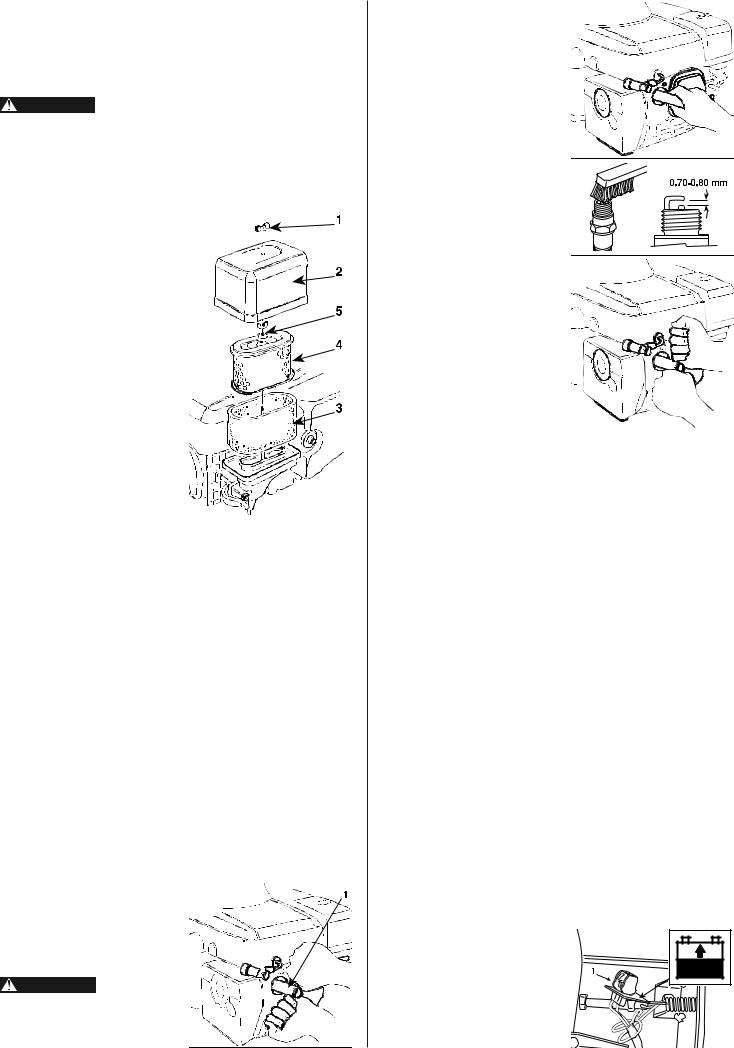
When the engine is stopped, close the fuel cock (1).
WARNING! |
Always take out the ignition key if leaving the |
machine unattended! |
|
IMPORTANT |
Tokeep the battery charged, do not leave the key |
in the «ON» position when the engine is not running.
5.4 CLEANING AND STORAGE CLEANING
After each mowing, clean the outside of the machine, empty the grass-catcher and shake it to remove residual grass and earth. Clean the plastic parts of the body with a damp sponge using water and detergent, taking care not to wet the engine, the electrical parts or the electronic card located under the dashboard.
IMPORTANT Never use hose-nozzles or harsh detergents for cleaning the body and engine!
WASHING THE INSIDE OF THE CUTTING DECK
The machine has to be put on firm ground with the stone-guard or grass-catcher in position. Washing the inside of the cutting deck and the collector channel is done by attaching a water hose to the connector (1) and running water through for a few minutes, with:
–the operator seated;
–the engine running;
–the drive in neutral;
–the parking brake on;
–the blade engaged.
When washing, the cutting deck should be in the fully lowered position. Take off the grass-catcher, empty and rinse it, and then put it in a position to assist quick drying.
STORAGE AND INACTIVITY FOR LONG PERIODS
If the machine is likely to be unused for a long period (more than 1 month). Lubricate all joints as directed in chapter 6.
EN 12
WARNING! Carefully remove any dry grass cuttings which may have been accumulated around the engine or silencer to prevent them from catching fire the next time the machine is used!
Before storing the unit for an extended period:
1. Be sure the storage area is free of excessive humidity and dust.
2. Drain the fuel tank and carburetor into a suitable gasoline con-
tainer.
– Remove the fuel tube (1) and drain the fuel tank.
– Loosen the carburetor drain screw (2) to drain the carburetor.
– Retighten the drain screw (2), connect the fuel tube (1) and
turn the fuel valve OFF.
3. Change the engine oil.
4.Remove the spark plug and pour about a tablespoon of clean engine oil into the cylinder.
|
Engine fuel is highly flammable. Store fuel in |
DANGER! |
|
ontainers specifically designed for this purpose. Replace |
|
caps of all fuel tanks and containers securely. |
|
|
|
IMPORTANT |
The battery must be kept in a cool and dry place. |
Before a long storage period (more than 1 month), always charge |
|
the battery. Recharge the battery before the next usage (chapter |
|
6). |
|
The next time the machine is used, check that there are no fuel leaks from the tubes, fuel cock or carburettor.
6.MAINTENANCE
|
Before cleaning, maintenance or repair work, |
WARNING! |
|
ake out the ignition key and read the relevant instructions. |
|
Wear suitable clothing and strong gloves. |
|
|
|
IMPORTANT |
Never get rid of used oil, fuel or other pollutants |
in unauthorised places!
ACCESS TO MECHANICAL PARTS
Lift the engine cover (1) to access the engine and mechanical parts below it.
To do so:
– put the machine on level ground, bring the cutting deck into the highest position and put blocks (2) of around 65 - 70 mm beneath the edge to hold up the deck during the following stages.
For mechanical drive models:
– engage the parking brake;
For hydrostatic drive models:
– put the drive release lever into the «ENGAGED» position (see chap. 4, n° 23), since it is necessary for the parking brake to be disengaged to ensure that the speed change lever has enough movement;
– remove the grass-catcher or stone-guard;
– unscrew the knob on the lever
(3) and put the lever into neutral «N» ( mechanical drive models), or in «R» ( hydrostatic drive models);
– open the access hatch (4) and unscrew the nut (5) with a 13 mm spanner;
– release the lever (6) so that the deck rests on the blocks and keep the lever moved sideways so that it is not in any of the notches. Hold the base of the seat (7) and tip the cover back.
On closing:
–check that the collector channel (8) is properly fitted onto its support (9) and resting on the guide as shown by the arrow (12);
–put the lever (3) into the «R» position and lower the cover (1) to the height of the levers (3) and (6);
–first put the lever (6) into its housing followed by lever (3). Lower the cover in line with the fastening screw (5).
|
|
|
When the cover (1) has been lowered check |
|
WARNING! |
|
|
|
hat the channel exit (8) is correctly lined up with the open- |
||
|
ing in the rear plate (10) and that it is resting on the support |
||
|
(11). The support (9) must never be removed or tampered |
||
|
with. What above mentioned is very important. If grass cut- |
||
|
tings get into the engine area, its performance can be seri- |
||
|
ously impaired. |
|
|
Then: |
|
||
– |
fully tighten the fixing nut (5); |
||
– |
put the lever (6) into the notch at position «7»; |
||
– |
take the blocks (2) away, and reassemble the knob on the lever |
||
|
(3) and the access hatch (4). |
||
ENGINE
The purpose of the maintenance schedule and adjustment is to keep the engine in the best operating condition. Inspect or service as scheduled in the table below.
WARNING! Shut off the engine before performing any maintenance. If the engine must be run, make sure the area is well ventilated. The exhaust contains poisonous carbon monoxide gas; exposure can cause loss of consciousness and may lead to death.
|
|
IMPORTANT |
Use only genuine Honda parts or their equiva- |
lent. The use of replacement parts which are not of equivalent |
|
quality may damage the engine. |
|
OIL CHANGE
Drain the oil while the engine is still warm to assure rapid and complete draining.
1.Remove the oil filler cap (1) and drain plug (2) to drain the oil. When refitti ng the plug (2), carefully re-position the seal.
2. Refill with the recommended oil (see page 18) and check the oil level.
ENGINE OIL CAPACITY: 1.1 liters
Wash your hands with soap and water after handling used oil.
|
|
NOTE |
Please dispose of used motor oil in a manner |
that is compatible with the environment. We suggest you take it |
|
in a sealed container to your local service station for reclamation. |
|
Do not throw it in the trash, pour it on the ground, or down a drain. |
|
|
13 EN |
AIR CLEANER SERVICE
A dirty air cleaner will restrict air flow to the carburetor. To prevent carburetor malfunction, service the air cleaner regularly. Service more frequently when operating the engine in extremely dusty areas.
WARNING! Never use gasoline or low flash point solents for cleaning the air cleaner element. A fire or explosion
could result.
|
|
IMPORTANT |
Never run the engine without the air cleaner. |
Rapid engine wear will result.
1.Remove the wing nut (1) and the air cleaner cover (2). Remove the elements and separate them. Carefully check both elements for holes or tears and replace if damaged.
2. Foam element (3): Clean in warm soapy water, rince and allow to dry thoroughly. Or clean in high flash-point solvent and allow to dry. Dip the element in clean engine oil and squeeze out all the excess.The engine will smoke during initial start-up if too much oil is felt in the foam.
3.Paper element (4): Tap the element lightly several times on a hard surface to remove excess dirt, or blow compressed air through the filter from the inside out. Never try to brush the dirt off; brushing will force dirt into the fibers. Replace the paper element if it is excessively dirty. Clean in warm, soapy water and rinse. Dry using compressed air blown from the inside out, or shake the element and allow it to air dry thoroughly. (Or clean in high flash point solvent, remove immediately, and allow to dry.).
|
|
NOTE |
Remember to reinstall the air cleaner grommet |
(5), replace the grommet if necessary. |
|
SPARK PLUG SERVICE
RECOMMENDED SPARK PLUG: BPR5ES (NGK)
Toensure proper engine operation, the spark plug must be properly gapped and free of deposits.
1.Remove the spark plug cap and use the proper size spark plug wrench (1) to remove the spark plug.
WARNING! If the engine has been running, the muffler will be very hot. Be careful not to touch the muffler.
EN 14
2.Visually inspect the spark plug. Discard it if the insulator is cracked or chipped. Clean the spark plug with a wire brush if it is to be reused.
3. Measure the plug gap with a feeler gauge. Correct as necessary by bending the side electrode. The gap should be: 0.70 - 0.80 mm.
4. Check that the spark plug washer is in good condition and thread the spark plug in by hand to prevent cross-thread- ing.
5.When installing a new spark plug, tighten 1/2 turn after the spark plug seats to compress the washer. When reinstalling a used spark plug, tighten 1/8 1/4 turn after the spark plug seats to compress the washer.
|
|
IMPORTANT |
The spark plug |
must be securely tightened. An improperly tightened spark plug |
|
can become very hot and may damage the engine. |
|
REAR AXLE
These are permanently lubricated with grease that does not need changing.
BATTERY
To ensure long life to the battery it is essential to keep it carefully maintained.
The machine battery must always be charged:
– before using the machine for the first time after purchase;
– before leaving the machine for a prolonged period of disuse;
– before starting up the machine after a prolonged period of disuse.
Carefully read and comply with the procedure for recharging described in the booklet coming with the battery.If the procedure is not followed or the battery is not charged, irreparable damage could be caused to the elements inside the battery. A flat battery must be recharged as soon as possible.
|
|
|
IMPORTANT |
Recharging must be done by using the “CB01” |
|
battery charger supplied wiith your machine. Other recharging sys- |
||
tems can irreversibly damage the battery. |
||
– |
follow the instructions given in the relative instruction booklet, |
|
– |
follow the instructions given in the battery booklet. |
|
The machine has a connector (1) for recharging, to be connected to the corresponding connector of the special “CB01” maintenance bat- tery-charger.
|
|
IMPORTANT |
Do not connect any other device than the “CB01” |
charger to this connector. |
|
ELECTRICAL SYSTEM
The electronic card and the electrical system are protected by:
– a self-resetting device which |
|
||||
breaks |
the |
circuit |
when |
2 |
|
there is a function fault, and |
|||||
(15 Amp) |
|||||
is accompanied by an audi- |
|
||||
ble signal which continues |
|
||||
until the key is removed. |
|
||||
When the problem has been |
|
||||
resolved |
the system auto- |
|
|||
matically resets after a few |
|
||||
seconds; |
|
|
|
||
– a 6.3 A delayed fuse (1) for |
|
||||
the protection of the general |
|
||||
and power |
circuits |
of the |
1 |
||
system. This must |
be re- |
||||
(6.3 Amp) |
|||||
placed after having elimi- |
|
||||
nated the fault. |
|
|
|||
A 15 A fuse (2) is also provided for protecting the recharge circuit.
When any of these devices are activated, the machine stops.
IMPORTANT A blown fuse must always be replaced by one of the same type and ampere rating, and never one of a different rating.
If you cannot find the cause of the protection device's activation, consult your Dealer.
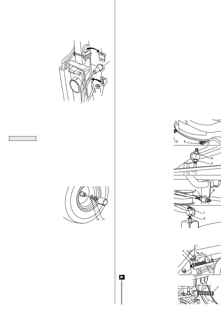
CHANGING WHEELS
Stop the machine on a flat surface and put blocks under a load-bear- ing part of the frame on the side that the wheel is to be changed.
The wheels are held by a snap ring (1) which can be taken off with a screwdriver.
The rear wheels are directly coupled to the axle shafts and fas-
tened by a key that forms part of the wheel's hub.
Before re-fitting a wheel, smear some grease on the axle and carefully re-fit the snap ring and washer (2).
|
|
NOTE |
Should you substitute one or both rear wheels, |
ensure that they are of the same diameter, and check that cutting |
|
deck is horizontal to prevent an uneven cut. |
|
CHANGING AND REPAIRING TYRES
Tyres are of the «Tubeless» type and therefore all puncture repairs will have to be carried out by a tyre-repair expert in accordance with the methods for this kind of tyres.
CHANGING BELTS
The motion from the engine to the rear axle and from the motor to the blade is obtained by two “V” belts, whose duration largely depends on how the machine is used.
Replacing belts is quite complicated because of dismantling and adjustments and must only be carried out by your Dealer.
|
|
NOTE |
Belts must always be replaced as soon as they |
are seen to be worn! ALWAYS USE MANUFACTURERʼS GENUINE SPARE BELTS!
CUTTING DECK ADJUSTMENT
The cutting deck should be properly adjusted to obtain a good cut. Height adjustments to the cutting deck are made through three linkages. Such adjustments are to be made on a flat surface after having ensured that the tyre pressures are correct.
|
|
NOTE |
For achieving good results from cutting, the front |
part should always be 2 - 4 mm lower than the rear.
To adjust the cutting deck so that it is parallel with the ground:
–put one 26 mm block (1) under the edge of the deck and one 32 mm block (2) under the rear edge, then put the lifting lever into the notch at position «1»;
– loosen the nuts (3 - 5 - 7) and the locknuts (4 - 6 - 8) so that
the deck is resting firmly on the blocks;
– turn the nut (3) until the righthand rear part of the deck starts to rise, and then tighten the relative locknut (4);
– screw down the nut (5) on the rod until the right-hand front part of the deck begins to rise, and then tighten the relative locknut (6);
– screw the nut (7) on the front left support until the deck in that
area begins to rise, and then
tighten the nut (8).
If you are unable to get the cutting deck parallel, consult your Dealer.
BRAKE ADJUSTMENT
The adjustment will need to be made while the parking brake is engaged.
For mechanical drive models:
Loosen the nut (1) which holds on the bracket (2) and turn the
nut (3) until the length of the
15 EN
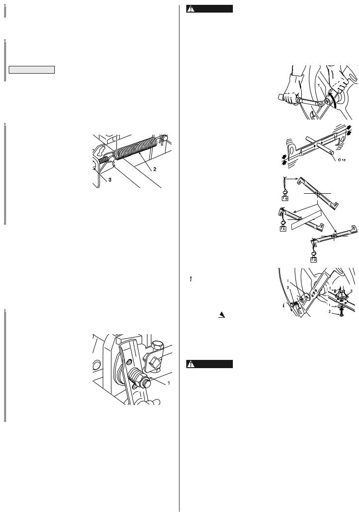
spring (4) is 46 - 48 mm inside the washers. When the adjustment has been made, tighten the nut (1).
 For hydrostatic drive models:
Turn the nut (5) until the length of the spring (6) is 45 - 47 mm in- |
|
side the washers. |
|
IMPORTANT |
Do not screw to below these values to avoid |
overloading the brake unit.
ADJUSTING DRIVE ENGAGEMENT
 For mechanical drive models:
If you should notice that forward drive power has dropped, you can adjust the regulating screw
(1) which is accessible through the hatchway beneath the seat. Undoing the screw and then lengthening the spring (2) will increase the drive ability. The best length for the spring is 86
mm measured from the outer ends of the spring. Once the adjustment has been made, tighten the locknuts (3). Excessive spring tension may cause too sudden engagement of the clutch, resulting in the machine tipping up.
ADJUSTMENT TO BLADE ENGAGEMENT AND BRAKE
If there seem to be problems in engaging the blade or the time for stopping when it has been disengaged is over 5 seconds, ask your Dealer for adjustment.
 For hydrostatic drive models:
ADJUSTING THE SPEED CHANGE LEVER
The speed change lever has a clutch device which keeps it in the position selected during forward movement and which returns the lever to neutral when brake is operated.
If the lever does not stay in position during working and has difficulty in returning to neutral,
the adjuster nut (1) will need to
be registered to restore normal functioning.
SHARPENING THE BLADE
Check that the blade is sharpened properly and firmly fixed to the bracket.
–A badly sharpened blade pulls at the grass and causes the lawn to turn yellow.
–A loose blade causes unusual vibrations and can be dangerous.
EN 16
WARNING! All operations on the blade (dismantling, harpening, balancing, remounting and/or replacing) require a certain familiarity and special tools. For safety reasons, go to a specialized centre if you do not have the right tools or ex-
perience.
To remove the blade, hold it firmly wearing strong gloves and undo the central screw (1).
Sharpen the two cutting edges using a medium grade grindi ng wheel and check the balance by holding the blade up with a round 18 mm diameter bar inserted in the central hole.
To ensure that it works properly without unusual vibrations any imbalance between the two parts of the blade must be below one gram.
This can be easily ascertained by putting a one gram weight on the lightest end of the blade. If it tends to go below the balanced position it means that the balance is correct, while if it stays up then the other end will have to be made lighter.
|
|
|
|
! |
|
|
|
|
G |
|
|
|
|
N |
|
|
|
|
O |
|
|
|
|
R |
|
|
|
|
|
W |
|
|
|
|
|
|
|
|
|
RIHT |
|
|
|
|
|
G |
! |
|
|
A damaged or |
|
|
|
|
|
|
WARNING! |
|
|
|
|
|
|
|
|
bent blade must always be |
|
|
|
|
|
|
||
|
|
|
|
|
|
|||
replaced; never try to repair |
|
|
|
|
|
|
||
|
|
|
|
|
|
|||
it! ALWAYS USE MANUFAC- |
|
|
|
|
|
|
||
TURER'S GENUINE SPARE |
|
|
|
|
|
|
||
BLADES |
! |
|
|
|
|
|
|
|
|
|
|
|
|
|
|
||
Only blades with the following codes must be used on this machine:
84109503/0
WARNING! When re-fitting the blade, always follow the ndicated sequence, making sure that the bladeʼs wings are facing towards the interior of the cutting deck and that the concave part of the cup spring (1) is pressing against the blade. Tighten the fixing screw (2) using a torque wrench set to 45-50 Nm. If the shaft hub (3) came off when dismantling the blade, make sure that the key (4) is firmly in its right position.
GUIDE TO SCHEDULED MAINTENANCE
This table is to help you maintain your machineʼs safety and performance. It shows the main maintenance and lubrication work, indicating the frequency with which it should be carried out.
To the right of each one there is a box where you can write the date or after how many hours of operation the work was carried out.
|
|
|
|
|
|
|
|
|
|
|
1. |
|
MACHINE |
|
|
|
|
|
|
|
|
1.1 |
Check of tight fixing and |
25 |
|
|
|
|
|
|
|
|
|
sharpness of blade |
|
|
|
|
|
|
|
||
|
|
|
|
|
|
|
|
|
||
1.2 |
|
Blade replacement |
100 |
|
|
|
|
|
|
|
|
|
|
|
|
|
|
|
|
|
|
1.3 |
Check of the |
25 |
|
|
|
|
|
|
|
|
|
transmission belt 1) |
|
|
|
|
|
|
|
||
1.4 |
Transmission belt |
– |
|
|
|
|
|
|
|
|
|
replacement 1) |
|
|
|
|
|
|
|
||
1.5 |
Checking the |
25 |
|
|
|
|
|
|
|
|
|
blade drive belt 1) |
|
|
|
|
|
|
|
||
1.6 |
Blade drive belt |
– |
|
|
|
|
|
|
|
|
|
replacement 1) |
|
|
|
|
|
|
|
||
1.7 |
Check and adjustment |
10 |
|
|
|
|
|
|
|
|
|
of brake |
|
|
|
|
|
|
|
||
|
|
|
|
|
|
|
|
|
||
1.8 |
Check and adjustment |
10 |
|
|
|
|
|
|
|
|
|
of drive |
|
|
|
|
|
|
|
||
|
|
|
|
|
|
|
|
|
||
1.9 |
Check blade |
10 |
|
|
|
|
|
|
|
|
|
engagement and brake |
|
|
|
|
|
|
|
||
|
|
|
|
|
|
|
|
|
||
1.10 |
Check of tight fixing |
25 |
|
|
|
|
|
|
|
|
|
|
of all the elements |
|
|
|
|
|
|
|
|
|
|
|
|
|
|
|
|
|
|
|
1.11 |
General lubrication 1) 2) |
25 |
|
|
|
|
|
|
|
|
2. |
|
ENGINE |
|
|
|
|
|
|
|
|
2.1 |
|
Check oil level 3) |
– |
|
|
|
|
|
|
|
2.2 |
Engine oil change 4) |
100 |
|
|
|
|
|
|
|
|
2.3 |
Oil filter replacement 4) |
– |
|
|
|
|
|
|
|
|
2.4 |
Check 3) and cleaning |
50 |
|
|
|
|
|
|
|
|
|
of air filter 5) 6) |
|
|
|
|
|
|
|
||
2.5 |
Air filter replacement 6) |
200 |
|
|
|
|
|
|
|
|
2.6 |
Check fuel filter 1) |
200 |
|
|
|
|
|
|
|
|
2.7 |
|
Fuel filter replacement 1) |
– |
|
|
|
|
|
|
|
2.8 |
Check and cleaning |
100 |
|
|
|
|
|
|
|
|
|
of spark plug points |
|
|
|
|
|
|
|
||
|
|
|
|
|
|
|
|
|
||
2.9 |
Replacement of spark |
200 |
|
|
|
|
|
|
|
|
|
plug |
|
|
|
|
|
|
|
||
|
|
|
|
|
|
|
|
|
||
1)Contact your Dealer.
2)General lubrication should be carried out whenever the machine is to be left unused for a long period.
3)Check each time used.
4)Operation to be performed also after the first 20 hours of operation.
5)Carry out maintenance of the air filter more frequently in the case of use on dusty ground.
6)Replace the paper element only.
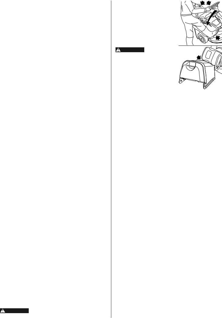
LAYING ON ITS SIDE
In order to easily reach beneath the machine, it can be turned onto its side after having removed the grass-catcher and completely emptied the fuel tank.
WARNING! This operation is to be performed with the ssistance of another person.
Having put the machine onto a firm and flat surface, engage the parking brake, put the cutting deck into position «7», firmly grip the steering wheel and the seat, and turn the machine onto its right hand side so that it rests on the grass-catcher (as shown), taking care not to damage plastic parts.
WARNING! Make sure that he machine is stable before starting any work and do not car- ry out work that may cause it to fall.
7. ENVIRONMENTAL PROTECTION
Environmental protection should be a priority of considerable importance when using the machine, for the benefit of both social coexistence and the environment in which we live.
–Try not to cause any disturbance to the surrounding area.
–Scrupulously comply with local regulations and provisions for the disposal of waste materials after sawing.
–Scrupulously comply with local regulations and provisions for the disposal of oils, petrol, damaged parts or any elements which have a strong impact on the environment; this waste must not be disposed of as normal waste, it must be separated and taken to specified waste disposal centres where the material will be recycled.
–At the time of decommissioning, do not pollute the environment with the machine, hand it over to a disposal centre, in accordance with the local laws in force.
17 EN

8. TROUBLESHOOTING
|
|
|
|
|
|
|
|
|
|
|
|
|
PROBLEM |
SITUATION |
|
LIKELY CAUSE |
|
|
|
|
SOLUTIONS |
|
|
|
|
|
|
|
|||||||
1. |
Pilot lamp off |
Key is in «ON» |
Electronic card in safety alert, due to: |
Put the key in the «OFF» position and look for the cause |
|||||||
|
|
position, engine |
|
|
of the problem: |
|
|
|
|||
|
|
stopped |
– |
badly connected battery |
– |
check connections |
|
||||
|
|
|
|
||||||||
|
|
|
– |
completely flat battery |
– |
recharge battery |
|
|
|
||
|
|
|
|
or eroded battery plates |
|
|
|
|
|
|
|
|
|
|
– |
battery terminals crossed |
– |
connect properly |
|
||||
|
|
|
– |
fuse blown |
– |
replace fuse (6.3 A - delayed) |
|
||||
|
|
|
– |
badly earthed |
– |
check connections |
|
||||
|
|
|
– |
electronic card wet |
– |
dry by air |
|
|
|
||
|
|
|
– |
earthed micro-switches |
– |
check connections |
|
||||
|
|
|
|
|
|
|
|
|
|
|
|
2. |
Starter motor not |
Key in «START» |
– |
insufficiently charged battery |
– |
recharge battery (if the problem continues, |
|
||||
working |
position and pilot |
|
|
|
consult your Dealer) |
|
|||||
|
|
lamp on |
– |
badly earthed |
– |
check the 15 A fuse |
|
||||
|
|
|
|
||||||||
|
|
|
|
|
– |
(if the problem continues, consult your Dealer) |
|||||
|
|
|
|
|
check connections |
|
|||||
|
|
Key in «START» |
– |
you are not ready for starting |
– |
check that the blade is disengaged |
|
||||
|
|
position and pilot |
|
|
|
(if the problem continues, check relevant micro-switch) |
|||||
|
|
lamp flashing |
|
|
– |
put the gear ( |
|
|
mechanical) or the lever ( |
|
hydrostatic) |
|
|
|
|
|
|
||||||
|
|
|
|
|
|
in neutral (N) |
|
|
|
||
|
|
|
|
|
|
|
|
|
|
|
|
3. |
Engine does not |
Key in «START» |
– |
no fuel supply |
– |
check fuel level |
|
|
|
||
start |
position |
|
|
– |
open fuel stop-cock |
|
|||||
|
|
|
|
|
– |
check fuel filter |
|
|
|
||
|
|
|
– |
faulty ignition |
– |
check that spark plug cap are firmly fitted |
|
||||
|
|
|
|
|
– |
check that the electrodes is clean and have the correct |
|||||
|
|
|
|
|
|
gap |
|
|
|
||
|
|
|
– |
insufficiently charged battery |
– |
recharge battery |
|
|
|
||
|
|
|
|
|
|
(if the problem continues, consult your Dealer) |
|||||
4. |
Starting is difficult |
Key in «ON», |
– |
fuel fault |
– |
clean or replace the air filter |
|
||||
or the engine runs |
engine running |
|
|
– |
flush out the float chamber |
|
|||||
erratically |
|
|
|
– |
empty fuel tank and refill with new fuel |
|
|||||
|
|
|
|
|
– check and, if necessary, replace fuel filter |
|
|||||
|
|
|
|
|
|
|
|||||
5. |
Weak engine |
Key in «ON», |
– |
forward speed too high in relation |
– |
reduce the forward speed and/or raise the cutting deck |
|||||
performance during |
engine running |
|
to cutting height |
|
|
|
|
|
|
|
|
cutting |
|
|
|
|
|
|
|
|
|
|
|
|
|
|
|
|
|
|
|
|
|
||
6. |
Engine stops |
Key in «ON», |
– |
you are not ready to engage the blade |
– |
sit firmly on seat |
|
|
|
||
when blade is |
engine running |
|
|
– |
(if problem continues, check micro-switch) |
|
|||||
engaged |
|
|
|
check that grass-catcher or stone-guard are correctly |
|||||||
|
|
|
|
|
|
in position (if problem continues, check micro-switch) |
|||||
|
|
|
|
|
|||||||
7. |
Engine stops |
Key in «ON», |
Electronic card in safety alert, due to: |
Put the key in the «OFF» position and look for the cause |
|||||||
|
|
engine running |
|
|
of the problem: |
|
|
|
|||
|
|
|
– |
earthed micro-switches |
– |
check connections |
|
||||
|
|
|
– |
flat battery |
– |
recharge battery |
|
|
|
||
|
|
|
– |
overload caused by the charge |
– |
contact your Dealer |
|
||||
|
|
|
|
regulator |
|
|
|
|
|
|
|
|
|
|
– |
badly connected battery (poor contact) |
– |
check battery connections |
|
||||
|
|
|
– |
engine badly earthed |
– |
check engine earth connection |
|
||||
EN 18
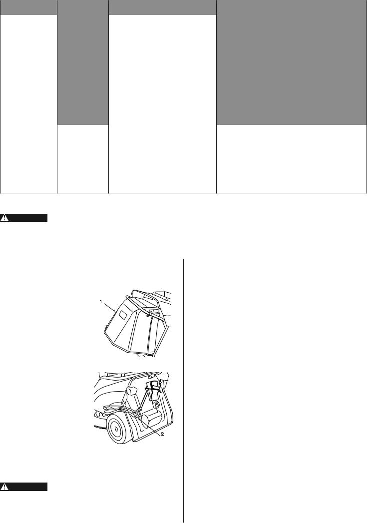
|
|
|
|
|
|
PROBLEM |
SITUATION |
|
LIKELY CAUSE |
|
SOLUTIONS |
|
|
|
|
|
|
8. Uneven cut and |
Key in «ON», |
– |
cutting deck not parallel to the ground |
– |
check tyre pressures |
poor grass collection |
engine running |
|
|
– |
re-align the cutting deck to the ground |
|
|
|
|
– |
check that the blade is fitted properly |
|
|
– |
blade cutting badly |
– |
sharpen or replace the blade |
|
|
|
|
– |
check the tension of the belt |
|
|
– |
forward speed too high compared |
– |
reduce forward speed and/or raise the cutting deck |
|
|
|
to height of grass |
– |
wait for grass to dry |
|
|
– |
collector channel is obstructed |
– |
remove the grass-catcher and empty the collector channel |
|
|
– |
cutting deck full of grass |
– |
clean the cutting deck |
|
|
|
|
|
|
9. Unusual vibrations |
Key in «ON», |
– |
the blade is imbalanced |
– |
balance or replace the damaged blade |
while working |
engine running |
– |
blade loose |
– |
check that the blade is firmly fitted |
|
|
||||
|
|
– |
fixing screws loose |
– |
check and tighten all the fixing screws of engine |
|
|
|
|
|
and the machine |
|
|
– |
cutting deck is obstructed |
– |
remove the grass-catcher, empty the collector channel |
|
|
|
|
|
and clean the inside of the cutting deck |
If problems continue after having carried out these operations, contact your Dealer.
WARNING! Do not take on complicated repair work if you don't have the necessary equipment and the technical knowledge. The guarantee is automatically revoked and the manufacturer declines all responsibility for any repairs which are badly done.
9. ACCESSORIES ON REQUEST
1. STONE-GUARD KIT
CG99900090H0
For use in place of the grass-cat- cher when the cuttings are not to be collected.
2. KIT FOR “MULCHING” CG99900036H0
It finely chops the grass cuttings and leaves them on the lawn, instead of collecting them in the grass-catcher
WARNING! For your safety it is strictly prohibited to fit ny other accessory other than those included in the above list, they have been exclusively designed for the model and
type of machine you are using.
19 EN

10. SPECIFICATIONS
MODELS |
HF1211 S |
HF1211 H |
Function |
|
|
Cutting of grass |
Electrical system |
|
12 V |
12 V |
Battery |
|
20 Ah |
20 Ah |
Engine: HONDA type |
|
GXV 340 |
GXV 340 |
Operating engine speed |
|
3100 r.p.m. |
3100 r.p.m |
Net Engine Power (*) |
|
6.6 kW / 3600 |
6.6 kW / 3600 |
Nominal Engine Power |
|
6.4 kW / 3100 |
6.4 kW / 3100 |
Front tires |
|
11 x 4-4 |
11 x 4-4 |
Rear tires |
|
15 x 6-6 |
15 x 6-6 |
Front tire pressure |
|
1.5 bar |
1.5 bar |
Rear tire pressure |
|
1.0 bar |
1.0 bar |
Fuel tank capacity |
|
3.6 liters |
3.6 liters |
Weight |
|
168 kg |
177 kg |
Speed |
|
|
|
in Forward drive |
|
— |
from 0 to 8.0 km/h |
in 1st |
|
1.6 km/h |
— |
in 2nd |
|
2.8 km/h |
— |
in 3rd |
|
4.2 km/h |
— |
in 4th |
|
4.7 km/h |
— |
in 5th |
|
7.0 km/h |
— |
in Reverse |
|
2.0 km/h |
from 0 to 3.7 km/h |
Inside turning circle (minimum diameter of uncut area), |
|
1.4 m |
1.4 m |
Left side |
|
||
|
|
|
|
Cutting height |
|
from 3 to 8 cm |
from 3 to 8 cm |
Cutting width |
|
71 cm |
71 cm |
Grass-catcher capacity |
|
170 liters |
170 liters |
Maximum noise and vibration levels |
|
|
|
MODELS |
|
HF1211 S |
HF1211 H |
Guaranteed acoustic power level (2000/14/EC, 2005/88/EC) |
dB(A) |
100 |
100 |
Measured acoustic power level (2000/14/EC, 2005/88/EC) |
dB(A) |
99.0 |
99.0 |
Measuring uncertainty |
dB(A) |
0.4 |
0.4 |
Sound pressure level at the ear (EN836:1997 / EN 836:1997+A4:2011) |
dB(A) |
83.6 |
83.6 |
Measuring uncertainty |
dB(A) |
0.4 |
0.4 |
Real measured value of acceleration on steering wheel (EN836:1997 / |
m/sec2 |
2.6 |
2.6 |
EN 836:1997+A4:2011) Measuring uncertainty |
m/sec2 |
0.4 |
0.4 |
Real measured value of acceleration on seat (EN 1032:1996) |
m/sec2 |
0.4 |
0.4 |
Measuring uncertainty |
m/sec2 |
0.2 |
0.2 |
|
(*) The power rating of the engine indicated in this document is the net po- |
||
|
wer output tested on a production engine for the engine models GX 340 and |
||
|
measured in accordance with SAE J1349 at 3600 r,p,m (Net Power) and at |
||
|
2800 r,p,m (Net Torque).Mass production engines may vary from this value. |
||
|
Actual power output for the engine installed in the final machine will vary de- |
||
|
pending on numerous factors, including the operating speed of the engine |
||
|
in application, environmental conditions, maintenance, and other variables. |
||
EN 20 |
|
|
|
PRÉSENTATION
Cher client,
Nous tenons avant tout à vous remercier de la préférence que vous avez accordée à nos produits et nous souhaitons que lʼemploi de cette nouvelle tondeuse autoportée vous réserve de grandes satisfactions et quʼelle réponde pleinement à vos attentes.
Ce manuel a été réalisé pour vous permettre de bien connaître votre machine et de l'utiliser dans les meilleures conditions de sécurité et d'efficacité. Nʼoubliez pas quʼil fait partie intégrante de la machine elle-même, conservez-le donc à portée de main pour le consulter à tout moment et assurez-vous qu'en cas de revente il accompagne bien la machine.
La machine a été conçue et fabriquée conformément aux normes en vigueur et ne sera fiable et sûre que si elle est utilisée pour la coupe et le ramassage du gazon, dans le plein respect des consignes contenues dans ce manuel (usage prévu); toute autre utilisation ou le non respect des consignes de sécurité lors de lʼutilisation, de lʼentretien et de la réparation de la machine indiquées dans le présent manuel sont considérés comme "emploi erroné" (Chap. 5): dans ce cas, la garantie perd tout effet, le fabricant décline toute responsabilité et reporte sur l'utilisateur les conséquences des dommages ou lésions causés à lui-même ou à autrui.
Au cas où vous remarqueriez une légère différence entre ce qui est décrit dans ces pages et la machine en votre possession,souvenez-vous que, compte tenu de l'amélioration technologique constante de ce produit, les informations contenues dans ce manuel peuvent être modifiées sans avis préalable ni obligation de mise à jour, étant toutefois bien entendu que les caractéristiques essentielles de sécurité et de fonctionnement restent inchangées. En cas de doute, n'hésitez pas à contacter votre concessionaire. Bon travail!
Assistance
Vous trouverez dans ce manuel toutes les indications nécessaires à la conduite de votre machine et au bon entretien de base que lʼutilisateur peut effectuer lui-même. Pour toute intervention non contenue dans ce livret, consultez votre concessionaire.
Inscrire ici le numéro de série de la machine
COMMENT CONSULTER LE MANUEL
Ce manuel décrit aussi bien la machine à transmission mécanique que celle à transmission hydrostatique ainsi que les versions dérivantde chaque équipement et la présence d'accessoires pas toujours disponibles dans les différentes zones de commercialisation.
Le symbole marque les différences à prendre en compte pour l'utilisation et est suivi de l'indication du type de transmission ou de la version à laquelle il se rapporte.
Dans le texte de ce manuel, certains paragraphes contenant des informations particulièrement importants sont marqués par différents degrés de mise en relief dont la signification est la suivante:
|
|
|
|
REMARQUE |
ou bien |
IMPORTANT |
Donne des précisions ou |
d'autres éléments à ce qui vient d'être indiqué, dans le but de ne pas endomma- |
|||
ger la machine ou de ne pas causer de dommages. |
|
||
|
|
|
|
ATTENTION! |
Possibilité de lésions à lʼutilisateur ou à autrui en cas de |
||
on respect des consignes. |
|
|
|
DANGER! |
Possibilité de lésions graves à lʼutilisateurou à autrui, et |
||
anger de mort, en cas de non respect des consignes.
Honda France Manufacturing S.A.S.
Pôle 45 - Rue des Châtaigniers - 45140 ORMES - FRANCE
All rights reserved
NOTICE ORIGINALE
MANUEL DʼUTILISATION
Tondeuse à gazon
HF1211
FRANÇAIS
SOMMAIRE
1. |
CONSIGNES DE SÉCURITÉ ..................................................... |
2 |
|
|
|
Contient les consignes dʼutilisation de la machine |
|
|
|
|
en toute sécurité |
|
|
|
2. |
IDENTIFICATION DE LA MACHINE ET DE SES PIÈCES ........ |
3 |
|
|
|
Explique comment identifier la machine ainsi que |
|
|
|
|
les principaux éléments qui la composent |
|
|
|
3. |
DÉBALLAGE ET MONTAGE ..................................................... |
4 |
|
|
|
Explique comment déballer et monter les pièces détachées |
|
|
|
4. |
COMMANDES ET OUTILS DE CONTRÔLE ............................. |
6 |
|
|
|
Indique la position et la fonction de toutes les commandes |
|
|
|
5. |
MODE D'EMPLOI ....................................................................... |
8 |
|
|
|
Contient toutes les indications pour bien travailler |
|
|
|
|
en toute sécurité |
8 |
|
|
|
5.1 |
Opérations précédant le travail ............................................ |
|
|
|
5.2 |
Mise en marche et déplacement .......................................... |
9 |
|
|
5.3 |
Tonte de la pelouse ............................................................ |
10 |
|
|
5.4 |
Nettoyage et stockage ....................................................... |
12 |
|
6. |
ENTRETIEN ............................................................................. |
13 |
|
|
|
Contient toutes les informations pour que la machine |
|
|
|
|
maintienne son efficacité |
|
|
|
7. |
PROTECTION DE LʼENVIRONNEMENT ................................ |
19 |
|
|
|
Fournit quelques conseils sur l'utilisation de la machine |
|
|
|
|
tout en respectant l'environnement |
|
|
|
8. |
PANNES ET REMÈDES ........................................................... |
19 |
|
|
|
Vous aide à résoudre rapidement tout éventuel |
|
|
|
|
problème d'utilisation |
|
|
|
9. |
ACCESSOIRES OPTIONNELS ............................................... |
20 |
|
|
|
Illustre les accessoires disponibles en cas d'exigences |
|
|
|
|
de travail particulières |
|
|
|
10. |
CARACTÉRISTIQUES TECHNIQUES ................................... |
21 |
|
|
|
Résume les principales caractéristiques de votre machine |
|
|
|
|
ADDRESSES DES PRINCIPAUX |
i |
|
|
|
CONCESSIONAIRES HONDA .................................................... |
|
||
|
“EC Declaration of Conformity” |
ii |
|
|
|
CONTENT OUTLINE .................................................................. |
|
||
|
|
|
|
1 FR |

1. CONSIGNES DE SÉCURITÉ
CONSIGNES GENERALES DE SÉCURITÉ
ATTENTION! Lire attentivement avant d'utiliser la machine.
A) FORMATION
1) Lire attentivement les instructions du présent manuel. Se familiariser avec lʼutilisation correcte et les commandes avant dʼutiliser la machine. Savoir arrêter le moteur rapidement.
2) Utiliser la machine pour lʼusage auquel elle est destinée, à savoir la tonte et le ramassage du gazon. Toute autre utilisation non expressément prévue par le manuel peut sʼavérer dangereuse et entraîner une détérioration de la machine. Dans ce cas, la garantie perd automatiquement tout effet et le constructeur décline toute responsabilité.
3) Ne jamais permettre à des enfants ou à des personnes qui ne sont pas suffisamment familiarisées avec les instructions dʼutiliser la machine. La réglementation locale peut fixer un âge minimum pour lʼutilisateur.
4) Ne jamais utiliser la machine lorsque:
– des personnes, en particulier des enfants, ou des animaux se trouvent à proximité;
– lʼutilisateur a absorbé des médicaments ou des substances réputés comme pouvant nuire à sa capacité de réflexe et de vigilance.
5) Garder à lʼesprit que lʼopérateur ou lʼutilisateur est responsable des accidents et des risques encourus par autrui ou par ses biens.
6) Ne pas transporter de passagers.
7) Le conducteur de la machine doit suivre attentivement les indications pour la conduite, à savoir:
– ne pas se laisser distraire et garder la concentration nécessaire pendant le travail;
– se rappeler quʼil nʼest pas possible de reprendre le contrôle dʼune machine qui glisse sur une pente en utilisant le frein. Les causes principales de la perte du contrôle sont:
– le manque dʼadhérence des roues;
– la vitesse excessive;
– le freinage insuffisant;
– la machine inadaptée à lʼutilisation;
– le manquede connaissance des réactionsaux conditions du terrain, surtout dans les pentes.
8) La machine est équipée dʼune série de micro-interrupteurs et de dispositifs de sécurité. La garantie et la responsabilité du constructeur tombent lorsque ceux-ci sont altérés ou éliminés.
B) PRÉPARATION
1) Toujours porter des chaussures résistantes et des pantalons longs pendant la tonte. Ne pas utiliser la machine lorsque lʼon est pieds nus ou en sandales.
2) Inspecter minutieusement la zone à tondre et éliminer tout objet étranger qui pourrait être projeté par la machine (pierres, morceaux de bois, fils de fer, os, etc.).
3) ATTENTION: DANGER ! Lʼessence est hautement inflammable.
– conserver le carburant dans des récipients spécialement prévus à cet effet;
– faire le plein à lʼaide dʼun entonnoir, uniquement à lʼextérieur, et ne pas fumer pendant cette opération ou pendant toute manipulation de carburant;
– faire le plein avant de démarrer le moteur; ne pas ajouter dʼessence et ne pas enlever le bouchon du réservoir de carburant lorsque le moteur est en marche ou tant quʼil est encore chaud;
– ne pas démarrer le moteur si de lʼessence a été répandue: éloigner la machine de la zone où le carburant a été renversé et ne provoquer aucune inflammation tant que le carburant ne sʼest pas évaporé et que les vapeurs ne se sont pas dissipées;
– refermer correctement le réservoir et le récipient en serrant convenablement les bouchons.
4) Remplacer les silencieux dʼéchappement défectueux.
5) Avant lʼutilisation, toujours procéder à une vérification générale et veiller en particulier à lʼaspect de la lame, des vis de fixation et de lʼensemble de coupe pour sʼassurer quʼils ne sont ni usés ni endommagés. Remplacer la lame et les vis endommagées ou usées par lots complets pour préserver le bon équilibrage.
6) Avant de commencer le travail,monter toujoursles protections(bac de ramassage ou déflecteur).
C) UTILISATION
1) Ne pas faire fonctionner le moteur dans un endroit confiné où les gaz nocifs contenant du monoxyde de carbone peuvent sʼaccumuler.
2) Tondre uniquement à la lumière du jour ou dans une lumière artificielle de bonne qualité.
3) Dans la mesure du possible, éviter de tondre de lʼherbe mouillée.
4) Avant de démarrer le moteur, désengager la lame, mettre le levier du changement de vitesse ( modèles à transmission mécanique) ou le levier de réglage de la vitesse ( modèles à transmission hydrostatique) au point mort et serrer le frein de stationnement.
FR 2
5)Ne pas tondre sur des pentes supérieures à 10° (17%).
6)Se rappeler quʼil nʼexiste pas de pente “sûre”. Se déplacer sur des terrains en pente demande une attention particulière. Pour éviter les renversements:
–ne pas sʼarrêter, repartir ou changer de direction brusquement dans les pentes et maintenir une vitesse modérée; modèles à
–embrayer doucement et garder toujours une vitesse engagée (
transmission mécanique) ou bien actionner doucement le levier de réglage de la vitesse aussi bien en marche avant qu'en marche arrière ( modèles à transmission hydrostatique) surtout en descente;
–réduire la vitesse avant dʼaborder les pentes et les virages serrés;
–faire attention aux dos dʼâne, aux cassis et aux dangers cachés;
–ne jamais tondre en travers de la pente.
7)Arrêter la lame en traversant des zones sans herbe et lever le plateau de coupe le plus haut possible.
8)Ne jamais utiliser la machine pour tondre lʼherbe si ses protecteurs sont endommagés ou en lʼabsence du bac de ramassage ou du déflecteur.
9)Ne jamais modifier le régulateur du moteur, ni mettre le moteur en surrégime.
10)Avant de quitter le poste de conduite:
–désengager la lame; modèles à transmission mécanique
–Mettre au point mort ( ) ou bien vérifier que le levier de réglage de la vitesse est bien retourné à la position de point mort ( modèles à transmission hydrostatique) et serrer le frein de stationnement.
–arrêter le moteur et enlever la clé de contact.
11)Débrayer la lame, arrêter le moteur et enlever la clé de contact:
–avant toute intervention sous le plateau de coupe ou dans le tunnel dʼéjection;
–avant toute opération de vérification, de nettoyage ou de réparation de la machine;
–après avoir heurté un objet étranger. Inspecter la machine pour voir si elle est endommagée et effectuer les réparations nécessaires avant toute nouvelle utilisation de la machine;
–si la machinecommence à vibrer de manière anormale, rechercher immédiatement la cause des vibrations et y remédier.
12)Désengager la lame pendant le transport et toutes les fois quʼelle nʼest pas utilisée. Désengager la lame et attendre quʼelle sʼarrête toutes les fois qu'on vide le bac de ramassage.
13)Arrêter le moteur et désengager la lame dans les cas suivants:
–avant de faire le plein de carburant;
–lors de la pose et la dépose du sac de ramassage.
14)Réduire les gaz avant dʼarrêter le moteur. Fermer le robinet dʼarrivée dʼessence après chaque utilisation, selon les indications du livret.
15)Tenir les mains et les pieds éloignés des pièces tournantes. Se tenir toujours à lʼécart de la goulotte dʼéjection.
16)Lʼutilisation dʼaccessoires autres que ceux recommandés par Honda peut occasionner des dommages sur votre tondeuse qui ne seront pas couverts par votre garantie.
D) ENTRETIEN ET REMISAGE
1)Maintenir tous les écrous et vis serrés afin dʼassurer des conditions dʼutilisation sûres. Un entretien régulier est essentiel pour la sécurité et le maintien du niveau des performances.
2)Ne jamais entreposer la machine avec du carburant dans le réservoir dans un local où les vapeurs dʼessence pourraient atteindre une flamme, une étincelle ou une forte source de chaleur.
3)Laisser le moteur refroidir avant de ranger la machine dans un local quelconque.
4)Pour réduire les risques dʼincendie, débarrasser la machine, en particulier le moteur, le pot dʼéchappement, le compartiment de la batterie ainsi que la zone de stockage du carburant, des feuilles, brins dʼherbe et des excès de graisse. Toujours vider le bac de ramassage et ne pas laisser de conteneurs de débris végétaux dans ou à proximité dʼun local.
5)Vérifier fréquemment que le déflecteur, le bac de ramassage et la grille dʼaspiration ne présentent aucune trace d'usure ou de détérioration. En cas dʼusure ou de détérioration, les remplacer.
6)Pour des raisons de sécurité, ne jamais utiliser la machine avec des pièces endommagées ou usées. Les pièces doivent être remplacées et non pas réparées. Utiliser des pièces de rechange dʼorigine (la lame doit toujours porter la marque ). Des pièces de qualité non équivalente peuvent endommager la machine et nuire à la sécurité.
7)Si le réservoir de carburant doit être vidangé, effectuer cette opération à lʼextérieur et lorsque le moteur est froid.
8)Porter des gants épais pour le démontage et le remontage de la lame.
9)Veiller au maintien de lʼéquilibrage de la lame lors de son affûtage.
10)Lorsque la machine doit être rangée ou laissée sans surveillance, abaisser le plateau de coupe.
11)Ne jamais laisser les clés sur la machine, à la portée des enfants ou de personnes non compétentes. Ne pas oublier dʼôter la clé de contact avant d'entreprendre toute opération d'entretien.
E) TRANSPORT
1) Si la machine doit être transportée sur un camion ou une remorque, abaisser le plateau de coupe, serrer le frein à main et la fixer solidement sur lʼengin de transport avec des cordes, des câbles ou des chaînes.

ÉTIQUETTES DE SÉCURITÉ
Votre machine doit être utilisée avec prudence. Dans ce but, des étiquettes destinées à vous rappelerles principales précautions dʼutilisationont été placées sur la machine sous forme de pictogrammes. Ces étiquettes sont considérées comme faisant partie intégrante de la machine.
Si une étiquette se détache ou devient illisible, contactez votre revendeur qui veillera à la remplacer.La signification des étiquettes est reportée ci-des- sous.
1 |
2 |
3 |
4 |
5 |
6 |
1 |
= |
Attention: Lire le mode dʼemploi avant dʼutiliser la machine. |
||||||||||
2 |
= Attention: Enlever la clé de contact et lire les instructions avant toute opération |
|||||||||||
3 |
|
dʼentretien ou de réparation. |
||||||||||
= Danger! Jet d'objets: Travailler après avoir monté le pare-pierres ou le bac. |
||||||||||||
4 |
= Danger! Jet d'objets:Les personnes doivent toujours se tenir loin de la machine. |
|||||||||||
5 |
= Danger! Renversement de la machine: Ne pas utiliser cette machine sur des |
|||||||||||
6 |
|
pentes supérieures à 10°. |
||||||||||
= Danger! Mutilation: S'assurer que les enfants se tiennent loin de la machine |
||||||||||||
|
|
|
lorsque le moteur est en marche. |
|||||||||
|
|
|
|
|
|
|
7 = Risque de coupures. Lame en mouvement. Ne |
|||||
7 |
||||||||||||
|
|
|
|
|
|
|
|
pas introduire les mains ou les pieds à lʼintérieur |
||||
|
|
|
|
|
|
|
|
du logement de la lame. |
||||
|
|
|
|
|
|
|
8 = Éviter dʼêtre happé par les courroies: Ne pas |
|||||
8 |
||||||||||||
|
|
|
|
|
|
|
|
faire fonctionner la machine lorsque les protections |
||||
|
|
|
|
|
|
|
|
ne sont pas en place. Rester à lʼécart des cour- |
||||
|
|
|
|
|
|
|
|
roies. |
||||
|
|
|
|
|
|
|
|
|
|
|
|
|
9 |
|
|
|
|
9 = Attention: ne pas modifier le microcontacteur. |
|||||||
|
|
|
|
|
|
|
||||||
|
|
|
|
|
|
|
|
|
|
|
||
|
10 |
|
|
11 |
|
|
|
|
|
|||
|
|
|
|
|
|
|
|
|
|
|
|
|
|
|
|
|
|
|
|
|
|
|
|
|
|
|
|
|
|
|
|
|
|
|
|
|
|
|
|
12 |
|
|
|
|
|
|
|
|
|
|
|
|
|
|
|
|
|
|
|
|
|
|
10 = |
Attention: Lire le manuel d'utilisateur avant l'utilisation de la tondeuse. |
|||||||||
11 = |
Attention: Le moteur dégage du monoxyde de carbone qui est un gaz toxique. |
|||||||||
|
|
|
|
Ne jamais le faire fonctionner dans un endroit clos. |
||||||
12 = |
Attention! Dès le démarrage, le pot d'échappement devient très chaud et le |
|||||||||
|
|
|
|
reste après l'arrêt du moteur. |
||||||
|
|
|
|
|
|
|
|
|
|
|
|
13 |
|
|
|
|
|
|
|
13 = Attention: Dès le démarrage, le pot d'échappe- |
|
|
|
|
|
|
|
|
|
|
|
ment devient très chaud et le reste après l'arrêt |
|
|
|
|
|
|
|
|
|
|
du moteur. |
|
|
|
|
|
|
|
|
|
|
14 = Produit recyclable. Contient du plomb. Ne pas |
|
|
|
|
|
|
|
|
|||
14 |
|
|
|
|
|
|
|
|||
|
|
|
|
|
|
|
|
|
|
jeter dans lʼenvironnement, et pour lʼélimination |
|
|
|
|
|
|
|
|
|
|
|
|
|
|
|
|
|
|
|
|
|
suivre les réglementations en vigueur. |
|
|
|
|
|
|
|
|
|
|
|
2.IDENTIFICATION DE LA MACHINE
ET DE SES PIÈCES
IDENTIFICATION DE LA MACHINE
Lʼétiquette appliquée sous le siège de conduite reporte les données essentielles et le numéro de série de chaque
machine (5).
Ce numéro sera indispensable toutes les fois que vous demanderez une intervention technique ou que vous commanderez des pièces détachées.
7 |
4 |
5 |
1 |
6 |
8 |
2 |
3 |
1.Niveau sonore selon les directives 2000/14/CE, 2005/88/CE
2.Marquage de conformité selon les directives 2006/42/CE,
3.2005/88/CE, 2004/108/CE
4.Année de fabrication
5.Type de machine
6.Numéro de série
7.Masse en kilogrammes
Le nom et lʼadresse du Fabricant sont reportés dans la “EC Declaration of Conformity” – CONTENT OUTLINE
8.contenue dans ce Manuel dʼInstructions. Puissance nominale du moteur
3 FR
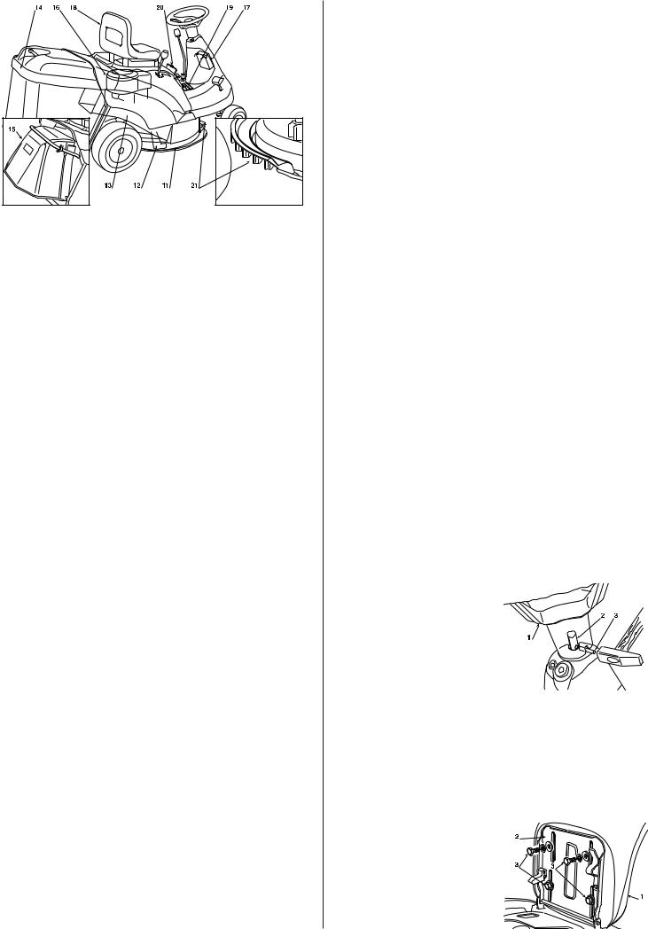
IDENTIFICATION DES PIÈCES PRINCIPALES
La machine est composée de pièces principalesdistinctes dont les fonctions sont les suivantes:
11.Plateau de coupe: carter qui renferme la lame tournante.
12.Lame: pièce servant à la tonte du gazon; les ailettes situées aux extrémités favorisent le passage de la pelouse tondue vers la goulotte d'éjection.
13.Goulotte d'éjection: pièce permettant la connexion entre le plateau de coupe et le bac de ramassage.
14.Bac de ramassage: sert d'une part à ramasser l'herbe tondue et constitue dʼautre part un élément de sécurité puisqu'il empêche les objets éventuellement pris par la lame d'être éjectés loin de la machine.
15.Pare-pierres ou déflecteur: monté à la place du bac de ramassage, il empêche les objets éventuellement pris par la lame d'être éjectés loin de la machine.
16.Moteur: met en mouvement la lame et permetla rotationdes roues; ses caractéristiques sont décrites dans un manuel à part.
17.Batterie: fournit l'énergie pour le démarrage du moteur; ses caractéristiques sont décrites dans un manuel à part.
18.Siège: c'est le poste de travail de l'opérateur; il est muni d'un capteur qui détecte sa présence pour une intervention des dispositifs de sécurité.
19.Étiquettes de prescriptions et de sécurité: rappellent les principales précautions à prendre pour opérer en toute sécurité; leur signification est fournie dans le chap. 1.
20.Porte dʼaccès: pour atteindre facilement la bougie et lʼécrou de fixage du couvercle du moteur.
21.Grille dʼaspiration: favorise le passage dʼair à lʼintérieur du plateau de coupe et empêche lʼexpulsion de corps étrangers vers lʼavant.
FR 4
3. DÉBALLAGE ET MONTAGE
Pour des raisons de stockage et de transport, certains éléments de la machine ne sont pas assemblés directement en usine mais doivent être montés après déballage. Pour leur montage, suivre ces simples consignes:
|
|
|
IMPORTANT |
Pour des raisons de transport, la machine est livrée |
|
sans huile moteur et sans essence. Avant de démarrer le moteur, effec- |
||
tuer le plein d'huile et d'essence selon les indications fournies dans le li- |
||
vret du moteur. |
|
|
|
|
Le désemballage et l'achèvement du montage doi- |
|
ATTENTION! |
|
vent être effectués sur une surface plane et solide, avec suffisamment dʼespace pour la manutention de la machine et des emballages, toujours en utilisant les outils appropriés.
DÉBALLAGE
Au moment de les déballer, veiller à bien récupérer toutes les pièces ainsi que l'équipement fournis et à ne pas endommager le plateau de coupe en faisant descendre la machine de la palette d'emballage.
L'emballage standard contient:
–la machine;
–le volant;
–le siège;
–les éléments du bac de ramassage;
–une enveloppe avec le manuel d'utilisation, les documents et l'équipement de montage qui comprend aussi 2 clés de démarrage, 1 goupille de blocage du volant et un fusible de rechange de 6,3 Ampère.
Il faut éliminer les emballages conformément aux dispositions locales en vigueur.
INSTALLATION DU VOLANT
Disposer la machine autoportée sur une surface plane et aligner les roues avant.
Engager le volant (1) sur la colonne de direction (2) de manière à ce que les rayons soient tournés vers le siège.
Faire correspondre le trou prévu dans l'axe du volant à celui de la colonne de direction pour pouvoir y introduire la goupille de blocage (3) fournie.
Pousser la goupille à l'intérieur à l'aide d'un marteau et sʼassurer qu'elle traverse bien.
|
|
REMARQUE |
Pour éviter d'abîmer le volant avec le marteau, pous- |
ser la tige à fond avec un pointeau de diamètre approprié. |
|
INSTALLATION DU SIÈGE
Monter le siège (1) sur la plaque (2) en utilisant les vis (3).
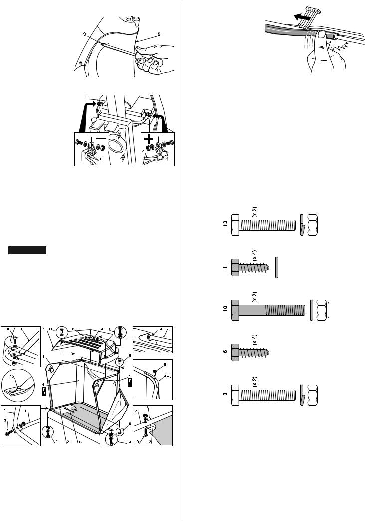
CONNEXION BATTERIE
La batterie (1) est logée dans le compartiment qui se trouve sous le volant; pour y accé- der, enlever la couverture en plastique (2) fixée par deux vis (3).
Enfiler le châssis ainsi formé dans la housse en toile en veillant à une bonne mise en place sur l'embase.
Accrocher tous les profils en plastique aux tubes du châssis à l'aide d'un tournevis (7).


 7
7
CLAK
Relier les deux fils rouges (4) au pôle positif (+) et les deux fils noirs (5) au pôle négatif (– ) à l'aide des boulons fournis et en procédant dans l'ordre indiqué.
Procéder à la recharge en suivant les indications du constructeur de la batterie.
|
|
IMPORTANT |
Afin d'éviter l'intervention de la protection de la carte |
électrique, il est impératif de ne pas mettre le moteur en marche avant |
|
la recharge complète! |
|
ATTENTION! Suivre les consignes de sécurité du constructeur de la batterie au cours de la manipulation et de la mise au rebut.
INSTALLATION DU BAC DE RAMASSAGE
Installer avant tout le châssis: fixer la partie supérieure (1), comprenant l'ouverture, à la partie inférieure (2) à l'aide des vis et des écrous fournis (3) et dans l'ordre dessiné.
Disposer les plaques d'angle (4) et (5) d'après le marquagede la droite (R ) et de la gauche (L ), les fixer au châssis à l'aide de quatre vis autotaraudeuses (6).
Introduire la poignée (8) à lʼaide des capsules en caoutchouc (14) dans les trous du couvercle (9) en veillant à positionner du côté droit lʼextrémité avec le coup de pointeau (15), fixer le tout au châssis à lʼaide des vis (10) dans lʼordre indiqué et achever lʼinstallation à lʼaide des quatre vis autotaraudeuses avant et arrière (11).
Placer les capsules en caoutchouc (14) dans les trous du couvercle (9) correspondants.
Pour finir, appliquer lʼentretoise de renforcement (12) sous le châssis en tournant la partie plate vers la toile et en utilisant les vis et les écrous fournis (13) dans lʼordre indiqué.
5 FR
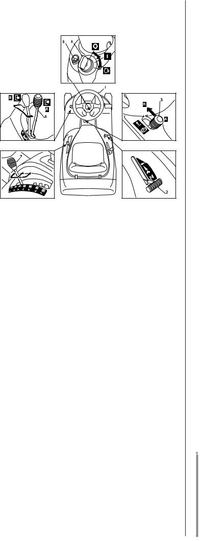
4.COMMANDES ET OUTILS
DE CONTRÔLE
1.VOLANT DE DIRECTION
Commande le braquage des roues avant.
2.LEVIER DʼACCÉLÉRATEUR
Règle la vitesse de rotation du moteur. Les positions sont indiquées sur une étiquette reportant les symboles suivants:
Position «STARTER» |
pour le démarrage |
|
Position |
«LENT» |
correspondant à la vitesse |
|
|
minimum |
Position |
«RAPIDE» |
correspondant à la vitesse |
|
|
maximum |
Au cours du déplacement, choisir une position intermédiaire entre «LENT» et «RAPIDE» tandis qu'il vaut mieux, durant la tonte, mettre le levier en position «RAPIDE».
3. LEVIER DE FREIN DE STATIONNEMENT
Ce levier sert à empêcher à la machine de se déplacer lorsquʼelle est à lʼarrêt: avant de descendre de la machine, ne pas oublier de lʼenclencher.
Enclencher le frein en appuyant à fond sur la pédale (11 - 21) et placer le levier sur «A»; en relâchant le pied de la pédale, le frein reste abaissé et bloqué dans cette position par le levier.
Désenclencher le frein de stationnement en appuyant à nouveau son pied sur la pédale: le levier se remettra sur «B».
FR 6
4. INTERRUPTEUR À CLÉ
Cette commande à clé compte trois positions:
«ARRÊT»
«MARCHE»
«DÉMARRAGE»
correspond à tout éteint; actionne tous les services;
met le démarreur en marche;
en relâchant la clé à partir de cette position, cette dernière se remet automatiquement sur «MARCHE».
5. VOYANT ET DISPOSITIFS DE SIGNALISATION
Ce voyant s'allume lorsque la clé (4) est placée sur «MARCHE» et reste toujours allumé au cours du travail.
Lorsqu'il clignote, cela veut dire qu'il manque une condition pour le démarrage du moteur (voir 5.3).
Lorsque la lame est embrayée, le bip sonore signale que le bac est plein (voir 5.3).
6. LEVIER DʼEMBRAYAGE ET DE FREIN LAME
Ce levier se règle sur deux positions indiquées par une étiquette et correspondant à:
Position «A» = LAME DÉBRAYÉE
Position «B» = LAME EMBRAYÉE
Si la lame est embrayée sans que les conditions de sécurité prévues soient respectées, le moteur s'arrête (voir 5.3).
Si la lame est débrayée (Pos. «A»), un frein est actionné en même temps et en bloque la rotation en cinq secondes.
7. LEVIER DE RÉGLAGE DE LA HAUTEUR DE COUPE
Ce levier se règle sur sept positions marquées de «1» à «7» sur lʼétiquette correspondante et indiquant autant de hauteurs de coupe comprises entre 3 et 8 cm.
Pour passer d'une position à lʼautre, déplacer latéralement le levier et le replacer sur lʼun des sept crans dʼarrêt.
Dans les modèles à transmission mécanique:
11. Pédale embrayage / Frein
Cette pédale exerce une double fonction: sur la première partie de sa course, elle actionne l'embrayage en activant ou en arrêtant la rotation des roues; sur la deuxième, elle agit en tant que frein sur les roues arrière.
|
|
REMARQUE |
Ne pas tenir le pied appuyé sur la pédale pendant |
la marche. |
|
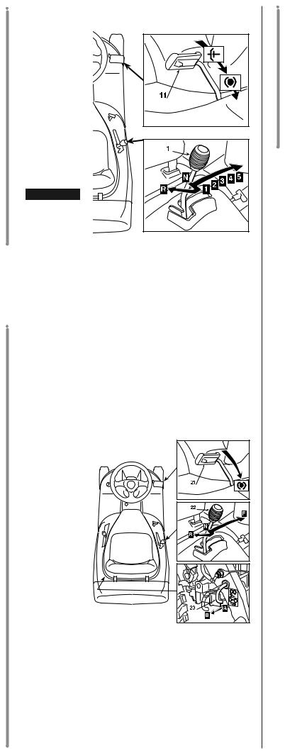
12. Levier de changement de vitesse
Ce levier se règle sur sept positions correspondant aux cinq vitesses avant, au point mort «N» et à la marche arrière «R».
Pour passer d'une vitesse à l'autre, appuyer sur la pédale (11) jusquʼà mi-course environ et déplacer le levier selon les indications reportées sur lʼé-
tiquette.
ATTENTION!
L'engagement de la marche arrière doit s'effectuer à l'arrêt.
Dans les modèles à transmission hydrostatique:
21. Pedale du frein
Dans les modèles à transmission hydrostatique, cette pédale nʼexerce quʼune fonction de frein, en agissant sur les roues arrière.
22. Levier de reglage de la vitesse
Ce levier a la fonction |
|||
dʼembrayer la traction |
|||
des roues et de mo- |
|||
duler la vitesse de la |
|||
machine, aussi |
bien |
||
en |
marche |
avant |
|
quʼen marche arrière. |
|||
On |
augmente |
gra- |
|
duellement la vitesse |
|||
de |
la machine |
en |
|
marche avant en dé- |
|||
plaçant le levier dans |
|||
la direction |
«F»; on |
||
engage la marche ar- |
|||
rière en déplaçant le |
|||
levier dans la direction |
|||
«R». |
|
|
|
Le retour en position de point mort «N» se fait |
|||
automatiquement quand on actionne la pédale du frein (21). |
|||
Le levier peut aussi être ramené manuellement au point mort sans ac- |
|
tionner la pédale. |
|
|
|
IMPORTANT |
Quand on enclenche le frein de stationnement (3), |
le levier se bloque en position «N» et ne peut être déplacé que |
|
lorsquʼon dégage le frein et relâche la pédale. |
|
23. Levier de deblocage de la transmission hydrostatique
Ce levier a deux positions, indiquées par une étiquette:
Position «A» |
= |
Transmission engagée: pour toutes les conditions |
Position «B» |
= |
dʼemploi, en marche et pendant la coupe de lʼherbe; |
Transmission débloquée: réduit beaucoup lʼeffort |
||
|
|
requis pour déplacer la machine à la main, lorsque |
|
|
le moteur est éteint. |
|
|
IMPORTANT |
Pour éviter d'endommager le groupe de trans- |
mission, cette opération ne doit être effectuée qu'à moteur arrêté avec le levier (22) en position «N».
7 FR
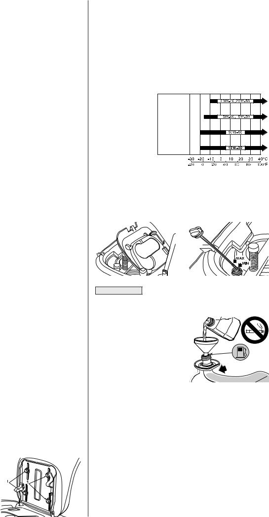
5. MODE DʼEMPLOI
RECOMMANDATIONS POUR LA SÉCURITÉ
|
|
Nʼutiliser la machine que pour effectuer ce à quoi |
|
DANGER! |
|
elle est destinée (tonte et ramassage de lʼherbe). |
||
Toute autre utilisation est considérée comme un "emploi impropre": |
||
dans ce cas, la garantie perd tout effet et le Fabricant décline toute |
||
responsabilité, en laissant à la charge de l'utilisateur les consé- |
||
quences des dommages ou des lésions causés à lui-même ou à au- |
||
trui. |
|
|
Font partie de lʼemploi impropre (à titre dʼexemple non exclusif): |
||
– transporter sur la machine ou sur une remorque dʼautres per- |
||
|
sonnes, enfants ou animaux; |
|
– remorquer ou pousser des charges; |
||
– |
utiliser la machine pour passer sur des terrains instables, glis- |
|
|
sants, glacés, rocailleux ou inégaux, des flaques ou des mares ne |
|
– |
permettant pas dʼévaluer la consistance du terrain; |
|
utiliser la machine pour ramasser des feuilles ou des détritus; |
||
– actionner la lame sur des terrains sans herbe. |
||
|
|
Ne pas modifier ou enlever les dispositifs de sé- |
|
DANGER! |
|
curité dont la machine est équipée. NE PAS OUBLIER QUE L'UTILI- |
||
SATEUR EST TOUJOURS RESPONSABLE DES DOMMAGES CAU- |
||
SÉS À AUTRUI. |
|
|
Avant d'utiliser la machine: |
||
– |
lire les consignes générales de sécurité (Chap. 1), en accordant |
|
|
une attention toute particulière à la marche et à la tonte sur des |
|
– |
terrains en pente; |
|
lire attentivement les instructions, se familiariser avec les com- |
||
mandes et apprendre à arrêter rapidement les lames et le moteur;
– tenir les mains et les pieds éloignés des pièces tournantes. Se tenir toujours à lʼécart de la goulotte dʼéjection.
Ne pas utiliser la machine en cas de mauvaises conditions physiques ou sous lʼeffet de médicaments ou de substances pouvant nuire à la capacité de réflexe et de vigilance.
Il est de responsabilité de lʼutilisateur dʼévaluer les risques potentiels du terrain à travailler et de prendre toutes les précautions nécessaires pour assurer sa sécurité, et celle dʼautrui, en particulier dans les pentes, sur les sols accidentés, glissants ou instables.
Ne pas laisser la machine arrêtée dans lʼherbe haute avec le moteur en marche afin dʼéviter de provoquer des incendies.
|
|
Cette machine ne doit pas être utilisée sur des |
|
ATTENTION! |
|
pentes supérieures à 10° (17%). |
||
|
|
|
IMPORTANT |
Toutesles références relatives aux positions des com- |
|
mandes sont celles illustrées dans le chapitre 4.
5.1 OPÉRATIONS PRÉCÉDANT LE TRAVAIL
RÉGLAGE DU SIÈGE
Le siège est fixé par quatre vis (1) quʼil faudra desserrer pour changer la position du siège en le faisant glisser le long des guides du support.
Une fois la position du siège réglée, serrer à fond les quatre vis.
FR 8
NIVEAU DʼHUILE ET APPROVISIONNEMENT
|
|
IMPORTANT |
Lʼhuile du moteur est un facteur majeur affectant les |
performances du moteur et sa durée de service. Des huiles végetales ou non-détergentes ne sont pas recommandées. Sʼassurer de vérifier le moteur placé sur une surface horizontal, le moteur étant arrêté.
Utiliser de lʼhuile Honda 4 temps ou une huile moteur équivalente, hautement détergente et de première qualité, certifiée pour satisfaire ou dépasser les exigences des constructeurs automobiles américains pour la classification des services SG, SF.Les huiles moteur classées SG, SF porteront cette indication sur le bidon.
Lʼhuile SAE 10W-30 est recommandée pour un
usage général, toute température. Si lʼon utilise une huile monograde, choisir la viscosisté approprée pour la température moyenne
de sa région.
Pour accéder à la jauge du niveau de lʼhuile, renverser le siège et ouvrir la porte se trouvant au-dessous.
Couper le contact et contrôler le niveau d'huile du moteur; il doit se trouver entre les encoches MIN et MAX de la jauge sans la visser. Ne pas oublier de revisser la jauge après le contrôle du niveau dʼhuile.
|
IMPORTANT |
|
• |
Ne jamais utiliser de mélange essence-huile. |
|
• |
Utiliser seulement de lʼessence sans plomb NO 95 ou 98. |
|
• Ne pas permettre aux saletés, dé- |
|
|
|
bris, etc. dʼentrer dans le réser- |
|
• |
voir. |
|
Ne pas utiliser du carburant sale |
|
|
|
ou polluant (eau, poussière, …), |
|
|
ni du carburant trop vieux. La qua- |
|
|
lité de lʼessence sans plomb di- |
|
|
minue au cours du temps. Ne pas |
MAX |
|
garder du carburant pendant plus |
|
|
dʼun mois. |
|
Faire le plein de carburant à l'aide d'un entonnoir en ayant soin de ne pas dépasser le niveau illustré dans la figure ci-contre.
Le contenu du réservoir est de 3,6 litres environ.
|
|
Le ravitaillement doit s'effectuer lorsque le |
|
DANGER! |
|
contact est coupé, en plein air ou en tout lieu suffisamment aéré. Ne |
||
pas oublier que les vapeurs d'essence sont inflammables! NE JA- |
||
MAIS APPROCHER UNE FLAMME DU RÉSERVOIR POUR EN VÉRI- |
||
FIER LE CONTENU ET NE PAS FUMER PENDANT LE RAVITAILLE- |
||
MENT. |
|
|
|
|
|
IMPORTANT |
Éviter de verser de l'essence sur les parties en plas- |
|
tique afin de ne pas les endommager en cas de fuites accidentaelles, rin- |
||
cer immédiatement à l'eau. |
||
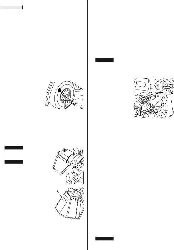
• Essence contenant de lʼalcool
IMPORTANT Si vous avez lʼintention dʼemployer de lʼessence conte-
nant de lʼalcool, assurez-vous que son indice dʼoctane est au moins aussi élevé que celui que recommande Honda (86). Il existe deux types de mé- lange essence/alcool : lʼun contenant de lʼalcooléthyliqueet lʼautre de lʼalcool méthylique.
Ne pas employer de mélange qui contienne plus de 10 % dʼalcool éthylique, ni dʼessence contenant de lʼalcool méthylique (méthyle ou alcool de bois), qui ne renferme ni cosolvants, ni inhibiteurs de corrosion pour lʼalcool méthylique.
Dans le cas dʼun mélange contenant de lʼalcool méthylique avec addition de cosolvants et dʼinhibiteurs de corrosion, limiter la proportion à 5 % dʼalcool méthylique.
La garantie ne couvre pas les dégâts causés au circuit dʼessence ou encore les problèmes de performances du moteur qui résultent de lʼemploi dʼessence contenant de lʼalcool. Honda ne saurait approuver lʼusage de carburants contenant de lʼalcool méthylique dans la mesure où leur caractère approprié nʼa pas encore été prouvé.
PRESSION DES PNEUS
Une bonne pression des pneus est la condition essentielle pour avoir un plateau de coupe parfaitement plat et une pelouse uniformément tondue.
Dévisser les capuchons de protection et brancher les valves à une prise d'air comprimé équipée d'un manomètre.
Les pressions doivent être: |
|
PNEUS AVANT |
1,5 bar |
PNEUS ARRIÈRE |
1,0 bar |
MONTAGE DES PROTECTIONS EN SORTIE (BAC DE RAMASSAGE OU PARE-PIERRES)
ATTENTION! Ne jamais utiliser la machine sans avoir installé les protections en sortie!
ATTENTION! Un microcontacteur coupe le moteur ou empêche son démarrage lorsque la lame est embrayée et que le bac ou le pare-pierres ne sont pas montés. IL EST TRÈS DANGEREUX D'ALTÉRER OU DE RÉDUIRE L'EFFICACITÉ DE CE DISPOSITIF!
Soulever la couverture mobile (1) et accrocher le bac de ramassage en introduisant les deux pivots dʼarticulation (2) dans les encoches des deux supports (3).
Un jeu pare-pierres (4) qui doit être monté en suivant les indications de la figure est fourni en option pour travailler sans bac de ramassage.
CONTRÔLE DU FONCTIONNEMENT DES SYSTÈMES DE SÉCURITÉ
Avant toute utilisation, vérifierque les systèmes de sécurité fonctionnent parfaitement; pour cela, simuler les différentes situationsdʼemploi prévues dans le tableau de la page 11 en sʼassurant de bien obtenir lʼeffet indiqué pour chaque situation.
CONTRÔLE DU SYSTÈME DE FREINAGE
Sʼassurer que la capacité de freinage de la machine est adaptée aux conditions dʼutilisation. Éviter de débuter le travail si on a des doutes sur lʼefficacités du frein. Si des doutes persistent, contacter votre concessionnaire.
CONTRÔLE DE LA LAME
Sʼassurer que la lame est bien aiguisée et solidement fixée sur son axe. Une lame mal aiguisée arrache l'herbe et fait donc jaunir la pelouse.
5.2 MISE EN MARCHE ET DÉPLACEMENT MISE EN MARCHE
DANGER! Les opérations relatives à la mise en marche doivent s'effectuer en plein air ou en tout lieu suffisamment aéré! NE PAS OUBLIER QUE LES GAZ D'ÉCHAPPEMENT DU MOTEUR SONT TOXIQUES!
Avant de démarrer le moteur:
– ouvrir le robinet d'essence(1), accessible à travers lʼouverture en correspondance de la roue postérieure droite;
– mettre le levier du changement de vitesse (( dans les modèles à transmission mécanique) ou bien le levier de réglage de la vitesse ( dans les modèles à transmission hydrostatique) au point mort («N»);
– sur les terrains en pente, enclencher le frein de stationnement;
– placer le levier d'embrayage de la lame en position de débrayage («A»).
Une fois ces opérations effectuées:
– placer le levier de l'accélérateur sur «STARTER», indiqué sur l'étiquette, en cas de démarrage à moteur froid, ou bien entre «LENT» et «RAPIDE» en cas de moteur déjà chaud;
– engager la clé dans le contacteur, la tourner sur «MARCHE» pour établir le contact électrique et la placer ensuite sur «DÉMARRAGE» pour démarrer le moteur; la relâcher dès qu'il a démarré.
Lorsque le moteur est en marche, placer l'accélérateur sur «LENT».
|
|
|
REMARQUE |
Si la mise en marche s'avère problématique, ne pas |
|
trop insister afin de ne pas décharger la batterie ou noyer le moteur. Re- |
||
placer la clé sur «ARRÊT», attendre un peu et répéter l'opération. Si le |
||
problème persiste, consulter le chapitre «8» de ce manuel. |
||
|
|
|
IMPORTANT |
Ne pas oublier que les dispositifs de sécurité empê- |
|
chent le démarrage du moteur lorsque: |
||
– |
la lame est embrayée; |
|
– |
la transmission nʼest pas au point mort (N) ; |
|
– |
lʼopérateur est absent et le frein de stationnement est déclenché. |
|
Lors dʼune tentative de «DEMARRAGE» dans lʼun des cas ci-dessus, le voyant de signalisation se mettra à clignoter.
DÉPLACEMENT
ATTENTION! La machine n'est pas homologuée pour circuler sur les voies publiques. Elle s'utilise exclusivement (conformément au Code de la Route) dans les zones privées fermées au trafic.
9 FR
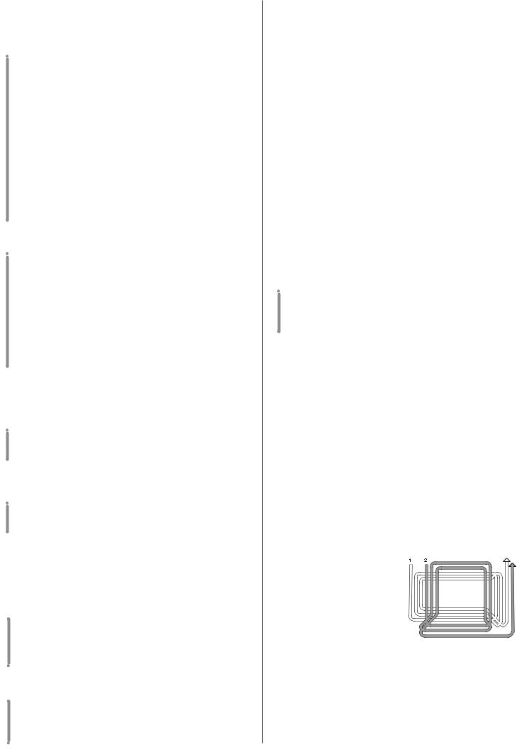
|
|
REMARQUE |
Dans les déplacements, la lame doit être débrayée et |
le plateau de coupe mis à la hauteur maximum (position «7»). |
|
Dans les modèles à transmission mécanique:
Placer la commande de l'accélérateur dans une position intermédiaire entre «LENT» et «RAPIDE» et mettre le levier de vitesse en première.
Tenir la pédale appuyée et dégager le frein de stationnement; relâcher graduellement la pédale qui passera ainsi de la fonction «frein» à la fonction «embrayage» et actionnera les roues arrière.
Relâcher la pédale graduellement pour éviter qu'un démarrage trop brusque ne cause le cabrage et la perte de contrôle du véhicule.
Le mouvement doit être continu et sans hésitation pour éviter le patinage excessif et la surchauffe de la courroie.
Atteindre graduellement la vitesse souhaitée en jouant sur l'accélérateur et le levier de vitesse; pour changer de vitesse, débrayer en utilisant la première partie de la course de la pédale.
Dans les modèles à transmission hydrostatique:
Placer la commande de l'accélérateur dans une position intermédiaire entre «LENT» et «RAPIDE»; appuyer sur la pédale du frein pour dégager le frein de stationnement, et relâcher la pédale.
Déplacer le levier de réglage de la vitesse en direction «F», et atteindre la vitesse désirée, en agissant sur le levier et sur lʼaccélérateur.
Il faut actionner le levier graduellement, pour éviter quʼun embrayage trop brusque de la traction aux roues puisse porter la machine à se cabrer et provoquer la perte de contrôle de la machine.
FREINAGE
Dans les modèles à transmission mécanique:
Pour freiner,pousser à fond sur la pédale en réduisant d'abord la vitesse à l'aide de l'accélérateur pour ne pas surcharger inutilement le frein.
Dans les modèles à transmission hydrostatique:
Pour freiner, appuyer sur la pédale du frein, qui actionnera en même temps le retour du levier de réglage de la vitesse en position «N».
MARCHE ARRIÈRE
Dans les modèles à transmission mécanique:
L'engagement de la marche arrière DOIT s'effectuer à l'arrêt. Actionner la pédale jusqu'à ce que la machine s'arrête, enclencher la marche arrière en déplaçant latéralement le levier et en le positionnant sur «R». Relâcher graduellement la pédale pour embrayer et ainsi, reculer.
Dans les modèles à transmission hydrostatique:
Lʼembrayage de la marche arrière DOIT se faire à lʼarrêt. Quand la machine est arrêtée, commencer la marche arrière en bougeant le levier de réglage de la vitesse en direction «R».
FR 10
5.3 TONTE DE LA PELOUSE
EMBRAYAGE DE LA LAME ET DÉPLACEMENT
Une fois sur la pelouse,
– placer l'accélérateur sur «RAPIDE»;
– embrayer la lame au moyen du levier en le portant sur «B»;
– le déplacement sʼobtient en agissant sur les commandes de réglage de la vitesse, en ayant soin de relâcher la pédale dʼembrayage avec les précautions décrites ci-dessus.
Embrayer toujours la lame lorsque le plateau est situé tout en haut et at- |
|||
teindre ensuite de manière graduelle la hauteur voulue. Pour avoir un bon |
|||
ramassage et une tonte uniforme, sélectionner la vitesse de déplacement |
|||
en fonction de la quantité dʼherbe à couper (hauteur et densité) et des condi- |
|||
tions dʼhumidité de la pelouse, en suivant ( |
dans les modèles à trans- |
||
mission mécanique) ces indications: |
|
|
|
– Herbe haute et touffue - pelouse humide 1ère vitesse |
|||
– Herbe moyenne |
2ème |
- 3ème vitesse |
|
– Herbe basse - pelouse sèche |
4ème |
vitesse |
|
|
|
||
REMARQUE |
La cinquième vitesse est prévue uniquement comme |
||
vitesse de déplacement sur du plat. |
|
|
|
Dans les modèles à transmission hydrostatique:
On obtient lʼadaptation de la vitesse aux conditions de la pelouse de façon graduelle et progressive, en agissant sur le levier de réglage de la vitesse.
Il est toutefois préférable de réduire la vitesse dès que le moteur peine; ne pas oublier en effet que la tonte ne sera jamais bonne si la vitesse est trop élevée.
Débrayer la lame et lever le plateau au maximum dès quʼun obstacle doit être passé.
RÉGLAGE DE LA HAUTEUR DE COUPE
Se fait au moyen du levier qui se règle sur 7 positions.
COMMENT OBTENIR UNE BONNE COUPE
1.La pelouse sera dʼautant plus belle quʼelle sera tondue alternativement en long et en large, à hauteur
2.constante.
Si la goulotte d'éjection se bouche, réduire la vitesse de déplacement car celle-ci peut être exessive par rapport aux conditions du gazon; si le problème persiste, les couteaux ne sont pas assez aiguisés ou le profil des ailettes est déformé (voir
3.chap. 8).
Lorsque l'herbe est très haute, il vaut mieux la tondre en deux fois: une première fois sur la pelouse avec le plateau à hauteur maximum et avec une largeur éventuellement réduite, une deuxième fois à la hauteur dé-
4.sirée.
Faire très attention à proximité des buissonset des bordures car ils pourraient endommager le parallélisme, le bord du plateau de coupe et le couteau.
 Loading...