

Page 1
POWER EQUIPMENT
LAWN MOWERS
*00X37 VF1 F04*
TONDEUSES À GAZON
RASENMÄHER
HRD536
HRH536
MANUEL DE L’UTILISATEUR
Honda France Manufacturing S.A.S.
Pôle 45 - Rue des Châtaigniers
45140 ORMES - FRANCE
OWNER’S MANUAL
BETRIEBSANLEITUNG
K4
Page 2

INHALTSVERZEICHNIS
INHALTSVERZEICHNIS . . . . . . . . . . . . . . . . . . . . . . . . . . . . . . . . . . . . . . . . . . . . . . . . . 2
ZUR BEACHTUNG . . . . . . . . . . . . . . . . . . . . . . . . . . . . . . . . . . . . . . . . . . . . . . . . . . . . . 5
SICHERHEITSHINWEISE. . . . . . . . . . . . . . . . . . . . . . . . . . . . . . . . . . . . . . . . . . . . . . . . 6
EINFÜHRUNG . . . . . . . . . . . . . . . . . . . . . . . . . . . . . . . . . . . . . . . . . . . . . . . . . . . . . . . 12
Erklärung der in dieser Bedienungsanleitung Verwendeten Kode . . . . . . . . . . . . . . . . 12
GRUNDLEGENDE ERKLÄRUNGEN . . . . . . . . . . . . . . . . . . . . . . . . . . . . . . . . . . . . . . 14
Bezeichnung der Bauteile . . . . . . . . . . . . . . . . . . . . . . . . . . . . . . . . . . . . . . . . . . . . . . . 14
Beschreibung der Sicherheitshinweise . . . . . . . . . . . . . . . . . . . . . . . . . . . . . . . . . . . . . 16
Erklärung der in dieser Bedienungsanleitung Verwendeten Symbole . . . . . . . . . . . . . 16
Typenschild der Maschine . . . . . . . . . . . . . . . . . . . . . . . . . . . . . . . . . . . . . . . . . . . . . . 16
VORBEITUNGEN UND KONTROLLEN VOR INBETRIEBNAHME. . . . . . . . . . . . . . . 18
Kontrolle des Grassacks . . . . . . . . . . . . . . . . . . . . . . . . . . . . . . . . . . . . . . . . . . . . . . . . 18
Befüllen des Kraftstofftanks . . . . . . . . . . . . . . . . . . . . . . . . . . . . . . . . . . . . . . . . . . . . . 20
Kraftstoffe . . . . . . . . . . . . . . . . . . . . . . . . . . . . . . . . . . . . . . . . . . . . . . . . . . . . . . . . . . . 22
Kontrolle des Luftfilters . . . . . . . . . . . . . . . . . . . . . . . . . . . . . . . . . . . . . . . . . . . . . . . . . 22
Kontrolle des Messers . . . . . . . . . . . . . . . . . . . . . . . . . . . . . . . . . . . . . . . . . . . . . . . . . 24
Einstellung der Schnitthöhe . . . . . . . . . . . . . . . . . . . . . . . . . . . . . . . . . . . . . . . . . . . . . 26
Ölstandkontrolle . . . . . . . . . . . . . . . . . . . . . . . . . . . . . . . . . . . . . . . . . . . . . . . . . . . . . . 28
Höheneinstellung des Lenkgestänges . . . . . . . . . . . . . . . . . . . . . . . . . . . . . . . . . . . . . 30
ANLASSEN UND ABSCHALTEN DES MOTORS . . . . . . . . . . . . . . . . . . . . . . . . . . . . 32
Anlassen des Motors . . . . . . . . . . . . . . . . . . . . . . . . . . . . . . . . . . . . . . . . . . . . . . . . . . 32
Abstellen des Motors . . . . . . . . . . . . . . . . . . . . . . . . . . . . . . . . . . . . . . . . . . . . . . . . . . 34
"Abgesoffener” Motor . . . . . . . . . . . . . . . . . . . . . . . . . . . . . . . . . . . . . . . . . . . . . . . . . . 34
EMPFEHLUNGEN FÜR DEN BETRIEB. . . . . . . . . . . . . . . . . . . . . . . . . . . . . . . . . . . . 36
Bedienung der Stellteile . . . . . . . . . . . . . . . . . . . . . . . . . . . . . . . . . . . . . . . . . . . . . . . . 38
Betrieb in Großen höhen . . . . . . . . . . . . . . . . . . . . . . . . . . . . . . . . . . . . . . . . . . . . . . . . 42
Ausleeren des Grasfangsacks . . . . . . . . . . . . . . . . . . . . . . . . . . . . . . . . . . . . . . . . . . . 42
WARTUNGSHINWEISE . . . . . . . . . . . . . . . . . . . . . . . . . . . . . . . . . . . . . . . . . . . . . . . . 44
Motorölwechsel . . . . . . . . . . . . . . . . . . . . . . . . . . . . . . . . . . . . . . . . . . . . . . . . . . . . . . . 46
Luftfilter . . . . . . . . . . . . . . . . . . . . . . . . . . . . . . . . . . . . . . . . . . . . . . . . . . . . . . . . . . . . . 48
Zündkerzenwechsel . . . . . . . . . . . . . . . . . . . . . . . . . . . . . . . . . . . . . . . . . . . . . . . . . . . 50
Nachstellen des Gaszugs . . . . . . . . . . . . . . . . . . . . . . . . . . . . . . . . . . . . . . . . . . . . . . . 52
Vergasereinstellung . . . . . . . . . . . . . . . . . . . . . . . . . . . . . . . . . . . . . . . . . . . . . . . . . . . 54
Einstellung des Rotostophebels . . . . . . . . . . . . . . . . . . . . . . . . . . . . . . . . . . . . . . . . . . 54
Einstellung des Fahrantriebshebels . . . . . . . . . . . . . . . . . . . . . . . . . . . . . . . . . . . . . . . 56
Messer . . . . . . . . . . . . . . . . . . . . . . . . . . . . . . . . . . . . . . . . . . . . . . . . . . . . . . . . . . . . . 60
Grassack pflege und Erneuerung . . . . . . . . . . . . . . . . . . . . . . . . . . . . . . . . . . . . . . . . . 64
Funkenfänger (Sonderzubehör) . . . . . . . . . . . . . . . . . . . . . . . . . . . . . . . . . . . . . . . . . . 66
Antriebsriemen . . . . . . . . . . . . . . . . . . . . . . . . . . . . . . . . . . . . . . . . . . . . . . . . . . . . . . . 66
Wartungsplan . . . . . . . . . . . . . . . . . . . . . . . . . . . . . . . . . . . . . . . . . . . . . . . . . . . . . . . . 68
STÖRUNGSBESEITIGUNG . . . . . . . . . . . . . . . . . . . . . . . . . . . . . . . . . . . . . . . . . . . . . 71
GERÄTETRANSPORT . . . . . . . . . . . . . . . . . . . . . . . . . . . . . . . . . . . . . . . . . . . . . . . . . 74
Zum Transport des Rasenmähers . . . . . . . . . . . . . . . . . . . . . . . . . . . . . . . . . . . . . . . . 74
Verladen des Rasenmähers . . . . . . . . . . . . . . . . . . . . . . . . . . . . . . . . . . . . . . . . . . . . . 76
LÄNGERE AUßERBETRIEBSETZUNG . . . . . . . . . . . . . . . . . . . . . . . . . . . . . . . . . . . 78
Längere Außerbetriebsetzung . . . . . . . . . . . . . . . . . . . . . . . . . . . . . . . . . . . . . . . . . . . 78
Wiederinbetriebnahme nach der Einlagerung . . . . . . . . . . . . . . . . . . . . . . . . . . . . . . . . 80
ADRESSEN . . . . . . . . . . . . . . . . . . . . . . . . . . . . . . . . . . . . . . . . . . . . . . . . . . . . . . . . . 82
TECHNISCHE DATEN . . . . . . . . . . . . . . . . . . . . . . . . . . . . . . . . . . . . . . . . . . . . . . . . . 84
2
Page 3

CONTENTS
CONTENTS . . . . . . . . . . . . . . . . . . . . . . . . . . . . . . . . . . . . . . . . . . . . . . . . . . . . . . . . . . .3
NOTE . . . . . . . . . . . . . . . . . . . . . . . . . . . . . . . . . . . . . . . . . . . . . . . . . . . . . . . . . . . . . . . .5
SAFETY INSTRUCTIONS . . . . . . . . . . . . . . . . . . . . . . . . . . . . . . . . . . . . . . . . . . . . . . . 8
INTRODUCTION . . . . . . . . . . . . . . . . . . . . . . . . . . . . . . . . . . . . . . . . . . . . . . . . . . . . . .13
Description of the codes used in this manual . . . . . . . . . . . . . . . . . . . . . . . . . . . . . . . .13
GENERAL DESCRIPTION . . . . . . . . . . . . . . . . . . . . . . . . . . . . . . . . . . . . . . . . . . . . . .15
Equipment identification . . . . . . . . . . . . . . . . . . . . . . . . . . . . . . . . . . . . . . . . . . . . . . . . .15
Safety label locations . . . . . . . . . . . . . . . . . . . . . . . . . . . . . . . . . . . . . . . . . . . . . . . . . . .17
Description of the symbols used in this manual . . . . . . . . . . . . . . . . . . . . . . . . . . . . . . .17
Identification of the machine . . . . . . . . . . . . . . . . . . . . . . . . . . . . . . . . . . . . . . . . . . . . .17
PREPARATIONS AND CHECKS BEFORE USE . . . . . . . . . . . . . . . . . . . . . . . . . . . . .19
Checking of the grass bag . . . . . . . . . . . . . . . . . . . . . . . . . . . . . . . . . . . . . . . . . . . . . . .19
Checking fuel level . . . . . . . . . . . . . . . . . . . . . . . . . . . . . . . . . . . . . . . . . . . . . . . . . . . . .21
Gasoline . . . . . . . . . . . . . . . . . . . . . . . . . . . . . . . . . . . . . . . . . . . . . . . . . . . . . . . . . . . . .23
Checking the air cleaner . . . . . . . . . . . . . . . . . . . . . . . . . . . . . . . . . . . . . . . . . . . . . . . .23
Checking blade condition . . . . . . . . . . . . . . . . . . . . . . . . . . . . . . . . . . . . . . . . . . . . . . . .25
Adjusting cutting height . . . . . . . . . . . . . . . . . . . . . . . . . . . . . . . . . . . . . . . . . . . . . . . . .27
Checking engine oil level . . . . . . . . . . . . . . . . . . . . . . . . . . . . . . . . . . . . . . . . . . . . . . . .29
Handle height adjustment system . . . . . . . . . . . . . . . . . . . . . . . . . . . . . . . . . . . . . . . . .31
STARTING AND STOPPING THE ENGINE . . . . . . . . . . . . . . . . . . . . . . . . . . . . . . . . .33
Starting the engine . . . . . . . . . . . . . . . . . . . . . . . . . . . . . . . . . . . . . . . . . . . . . . . . . . . . .33
Stopping the engine . . . . . . . . . . . . . . . . . . . . . . . . . . . . . . . . . . . . . . . . . . . . . . . . . . . .35
Flooded engine . . . . . . . . . . . . . . . . . . . . . . . . . . . . . . . . . . . . . . . . . . . . . . . . . . . . . . .35
OPERATING HINTS AND TIPS . . . . . . . . . . . . . . . . . . . . . . . . . . . . . . . . . . . . . . . . . .37
Controls and mowing procedures . . . . . . . . . . . . . . . . . . . . . . . . . . . . . . . . . . . . . . . . .39
Using the mower at high altitudes . . . . . . . . . . . . . . . . . . . . . . . . . . . . . . . . . . . . . . . . .43
Emptying the grass bag . . . . . . . . . . . . . . . . . . . . . . . . . . . . . . . . . . . . . . . . . . . . . . . . .43
MAINTENANCE . . . . . . . . . . . . . . . . . . . . . . . . . . . . . . . . . . . . . . . . . . . . . . . . . . . . . .45
Changing the engine oil . . . . . . . . . . . . . . . . . . . . . . . . . . . . . . . . . . . . . . . . . . . . . . . . .47
Air cleaner . . . . . . . . . . . . . . . . . . . . . . . . . . . . . . . . . . . . . . . . . . . . . . . . . . . . . . . . . . .49
Spark plug . . . . . . . . . . . . . . . . . . . . . . . . . . . . . . . . . . . . . . . . . . . . . . . . . . . . . . . . . . .51
Throttle control cable adjustment . . . . . . . . . . . . . . . . . . . . . . . . . . . . . . . . . . . . . . . . . .53
Carburettor adjustment . . . . . . . . . . . . . . . . . . . . . . . . . . . . . . . . . . . . . . . . . . . . . . . . .55
Rotostop safety lever clearance . . . . . . . . . . . . . . . . . . . . . . . . . . . . . . . . . . . . . . . . . .55
Drive clutch lever clearance . . . . . . . . . . . . . . . . . . . . . . . . . . . . . . . . . . . . . . . . . . . . . .57
Shift lever adjustment . . . . . . . . . . . . . . . . . . . . . . . . . . . . . . . . . . . . . . . . . . . . . . . . . .59
Cutting blade . . . . . . . . . . . . . . . . . . . . . . . . . . . . . . . . . . . . . . . . . . . . . . . . . . . . . . . . .61
Grass bag cleaning and replacement . . . . . . . . . . . . . . . . . . . . . . . . . . . . . . . . . . . . . .65
Spark arrester (optional part) . . . . . . . . . . . . . . . . . . . . . . . . . . . . . . . . . . . . . . . . . . . . .67
Drive belt . . . . . . . . . . . . . . . . . . . . . . . . . . . . . . . . . . . . . . . . . . . . . . . . . . . . . . . . . . . .67
Maintenance schedule . . . . . . . . . . . . . . . . . . . . . . . . . . . . . . . . . . . . . . . . . . . . . . . . . .69
TROUBLESHOOTING . . . . . . . . . . . . . . . . . . . . . . . . . . . . . . . . . . . . . . . . . . . . . . . . . 72
TRANSPORT . . . . . . . . . . . . . . . . . . . . . . . . . . . . . . . . . . . . . . . . . . . . . . . . . . . . . . . .75
To transport the mower . . . . . . . . . . . . . . . . . . . . . . . . . . . . . . . . . . . . . . . . . . . . . . . . .75
Loading the mower . . . . . . . . . . . . . . . . . . . . . . . . . . . . . . . . . . . . . . . . . . . . . . . . . . . .77
STORAGE . . . . . . . . . . . . . . . . . . . . . . . . . . . . . . . . . . . . . . . . . . . . . . . . . . . . . . . . . . .79
Preparations for storing the mower . . . . . . . . . . . . . . . . . . . . . . . . . . . . . . . . . . . . . . . .79
Using the mower after a storage period . . . . . . . . . . . . . . . . . . . . . . . . . . . . . . . . . . . . .81
ADDRESSES . . . . . . . . . . . . . . . . . . . . . . . . . . . . . . . . . . . . . . . . . . . . . . . . . . . . . . . .82
TECHNICAL SPECIFICATIONS . . . . . . . . . . . . . . . . . . . . . . . . . . . . . . . . . . . . . . . . . .85
3
Page 4

TABLE DES MATIÈRES
TABLE DES MATIÈRES . . . . . . . . . . . . . . . . . . . . . . . . . . . . . . . . . . . . . . . . . . . . . . . . 4
NOTE . . . . . . . . . . . . . . . . . . . . . . . . . . . . . . . . . . . . . . . . . . . . . . . . . . . . . . . . . . . . . . . 5
CONSIGNES DE SÉCURITÉ . . . . . . . . . . . . . . . . . . . . . . . . . . . . . . . . . . . . . . . . . . . . 10
INTRODUCTION . . . . . . . . . . . . . . . . . . . . . . . . . . . . . . . . . . . . . . . . . . . . . . . . . . . . . 13
Explication des codes utilisés dans ce manuel . . . . . . . . . . . . . . . . . . . . . . . . . . . . . . . 13
DESCRIPTION GÉNÉRALE . . . . . . . . . . . . . . . . . . . . . . . . . . . . . . . . . . . . . . . . . . . . 15
Identification du matériel . . . . . . . . . . . . . . . . . . . . . . . . . . . . . . . . . . . . . . . . . . . . . . . . 15
Emplacement des étiquettes de sécurité . . . . . . . . . . . . . . . . . . . . . . . . . . . . . . . . . . . 17
Explication des symboles utilisés dans le manuel . . . . . . . . . . . . . . . . . . . . . . . . . . . . 17
Identification de la machine . . . . . . . . . . . . . . . . . . . . . . . . . . . . . . . . . . . . . . . . . . . . . 17
Préparations et vérifications avant utilisation . . . . . . . . . . . . . . . . . . . . . . . . . . . . . . . . 19
Vérification du sac de ramassage . . . . . . . . . . . . . . . . . . . . . . . . . . . . . . . . . . . . . . . . . 19
Vérification du niveau d’essence . . . . . . . . . . . . . . . . . . . . . . . . . . . . . . . . . . . . . . . . . 21
Carburant . . . . . . . . . . . . . . . . . . . . . . . . . . . . . . . . . . . . . . . . . . . . . . . . . . . . . . . . . . . 23
Vérification du filtre à air . . . . . . . . . . . . . . . . . . . . . . . . . . . . . . . . . . . . . . . . . . . . . . . . 23
Vérification de l’état de la lame . . . . . . . . . . . . . . . . . . . . . . . . . . . . . . . . . . . . . . . . . . . 25
Réglage de la hauteur de coupe . . . . . . . . . . . . . . . . . . . . . . . . . . . . . . . . . . . . . . . . . . 27
Vérification du niveau de l’huile moteur . . . . . . . . . . . . . . . . . . . . . . . . . . . . . . . . . . . . 29
Système de réglage de la hauteur du guidon . . . . . . . . . . . . . . . . . . . . . . . . . . . . . . . . 31
MISE EN MARCHE ET ARRÊT DU MOTEUR . . . . . . . . . . . . . . . . . . . . . . . . . . . . . . . 33
Mise en marche du moteur . . . . . . . . . . . . . . . . . . . . . . . . . . . . . . . . . . . . . . . . . . . . . . 33
Arrêt du moteur . . . . . . . . . . . . . . . . . . . . . . . . . . . . . . . . . . . . . . . . . . . . . . . . . . . . . . . 35
Moteur noyé . . . . . . . . . . . . . . . . . . . . . . . . . . . . . . . . . . . . . . . . . . . . . . . . . . . . . . . . . 35
CONSEILS D’UTILISATION . . . . . . . . . . . . . . . . . . . . . . . . . . . . . . . . . . . . . . . . . . . . 37
Commandes et procédure de tonte . . . . . . . . . . . . . . . . . . . . . . . . . . . . . . . . . . . . . . . 39
Fonctionnement en haute altitude . . . . . . . . . . . . . . . . . . . . . . . . . . . . . . . . . . . . . . . . . 43
Vidage du sac de ramassage . . . . . . . . . . . . . . . . . . . . . . . . . . . . . . . . . . . . . . . . . . . . 43
ENTRETIEN . . . . . . . . . . . . . . . . . . . . . . . . . . . . . . . . . . . . . . . . . . . . . . . . . . . . . . . . . 45
Changement de l’huile moteur . . . . . . . . . . . . . . . . . . . . . . . . . . . . . . . . . . . . . . . . . . . 47
Filtre à air . . . . . . . . . . . . . . . . . . . . . . . . . . . . . . . . . . . . . . . . . . . . . . . . . . . . . . . . . . . 49
Bougie d’allumage . . . . . . . . . . . . . . . . . . . . . . . . . . . . . . . . . . . . . . . . . . . . . . . . . . . . 51
Réglage du câble de commande des gaz . . . . . . . . . . . . . . . . . . . . . . . . . . . . . . . . . . . 53
Réglage du carburateur . . . . . . . . . . . . . . . . . . . . . . . . . . . . . . . . . . . . . . . . . . . . . . . . 55
Jeu au levier de sécurité rotostop . . . . . . . . . . . . . . . . . . . . . . . . . . . . . . . . . . . . . . . . . 55
Jeu au levier d’embrayage d’avancement . . . . . . . . . . . . . . . . . . . . . . . . . . . . . . . . . . 57
Réglage du levier de changement de vitesse . . . . . . . . . . . . . . . . . . . . . . . . . . . . . . . . 59
Lame de coupe . . . . . . . . . . . . . . . . . . . . . . . . . . . . . . . . . . . . . . . . . . . . . . . . . . . . . . . 61
Nettoyage et changement du sac de ramassage . . . . . . . . . . . . . . . . . . . . . . . . . . . . . 65
Pare-étincelles (pièce en option) . . . . . . . . . . . . . . . . . . . . . . . . . . . . . . . . . . . . . . . . . 67
Courroie de transmission . . . . . . . . . . . . . . . . . . . . . . . . . . . . . . . . . . . . . . . . . . . . . . . 67
Calendrier d’entretien . . . . . . . . . . . . . . . . . . . . . . . . . . . . . . . . . . . . . . . . . . . . . . . . . . 70
DÉPISTAGE DES PANNES . . . . . . . . . . . . . . . . . . . . . . . . . . . . . . . . . . . . . . . . . . . . . 73
TRANSPORT . . . . . . . . . . . . . . . . . . . . . . . . . . . . . . . . . . . . . . . . . . . . . . . . . . . . . . . . 75
Pour transporter la tondeuse . . . . . . . . . . . . . . . . . . . . . . . . . . . . . . . . . . . . . . . . . . . . 75
Chargement de la tondeuse . . . . . . . . . . . . . . . . . . . . . . . . . . . . . . . . . . . . . . . . . . . . . 77
REMISAGE . . . . . . . . . . . . . . . . . . . . . . . . . . . . . . . . . . . . . . . . . . . . . . . . . . . . . . . . . . 79
Préparation pour le remisage . . . . . . . . . . . . . . . . . . . . . . . . . . . . . . . . . . . . . . . . . . . . 79
Réutilisation après remisage . . . . . . . . . . . . . . . . . . . . . . . . . . . . . . . . . . . . . . . . . . . . . 81
ADRESSES . . . . . . . . . . . . . . . . . . . . . . . . . . . . . . . . . . . . . . . . . . . . . . . . . . . . . . . . . 82
SPÉCIFICATIONS TECHNIQUES . . . . . . . . . . . . . . . . . . . . . . . . . . . . . . . . . . . . . . . . 86
4
Page 5

ZUR BEACHTUNG / NOTE / NOTE
. . . . . . . . . . . . . . . . . . . . . . . . . . . . . . . . . . . . . . . . . . . . . . . . . . . . . . . . . . . . . . . . . . . . .
. . . . . . . . . . . . . . . . . . . . . . . . . . . . . . . . . . . . . . . . . . . . . . . . . . . . . . . . . . . . . . . . . . . . .
. . . . . . . . . . . . . . . . . . . . . . . . . . . . . . . . . . . . . . . . . . . . . . . . . . . . . . . . . . . . . . . . . . . . .
. . . . . . . . . . . . . . . . . . . . . . . . . . . . . . . . . . . . . . . . . . . . . . . . . . . . . . . . . . . . . . . . . . . . .
. . . . . . . . . . . . . . . . . . . . . . . . . . . . . . . . . . . . . . . . . . . . . . . . . . . . . . . . . . . . . . . . . . . . .
. . . . . . . . . . . . . . . . . . . . . . . . . . . . . . . . . . . . . . . . . . . . . . . . . . . . . . . . . . . . . . . . . . . . .
. . . . . . . . . . . . . . . . . . . . . . . . . . . . . . . . . . . . . . . . . . . . . . . . . . . . . . . . . . . . . . . . . . . . .
. . . . . . . . . . . . . . . . . . . . . . . . . . . . . . . . . . . . . . . . . . . . . . . . . . . . . . . . . . . . . . . . . . . . .
. . . . . . . . . . . . . . . . . . . . . . . . . . . . . . . . . . . . . . . . . . . . . . . . . . . . . . . . . . . . . . . . . . . . .
. . . . . . . . . . . . . . . . . . . . . . . . . . . . . . . . . . . . . . . . . . . . . . . . . . . . . . . . . . . . . . . . . . . . .
. . . . . . . . . . . . . . . . . . . . . . . . . . . . . . . . . . . . . . . . . . . . . . . . . . . . . . . . . . . . . . . . . . . . .
. . . . . . . . . . . . . . . . . . . . . . . . . . . . . . . . . . . . . . . . . . . . . . . . . . . . . . . . . . . . . . . . . . . . .
. . . . . . . . . . . . . . . . . . . . . . . . . . . . . . . . . . . . . . . . . . . . . . . . . . . . . . . . . . . . . . . . . . . . .
. . . . . . . . . . . . . . . . . . . . . . . . . . . . . . . . . . . . . . . . . . . . . . . . . . . . . . . . . . . . . . . . . . . . .
. . . . . . . . . . . . . . . . . . . . . . . . . . . . . . . . . . . . . . . . . . . . . . . . . . . . . . . . . . . . . . . . . . . . .
. . . . . . . . . . . . . . . . . . . . . . . . . . . . . . . . . . . . . . . . . . . . . . . . . . . . . . . . . . . . . . . . . . . . .
. . . . . . . . . . . . . . . . . . . . . . . . . . . . . . . . . . . . . . . . . . . . . . . . . . . . . . . . . . . . . . . . . . . . .
. . . . . . . . . . . . . . . . . . . . . . . . . . . . . . . . . . . . . . . . . . . . . . . . . . . . . . . . . . . . . . . . . . . . .
. . . . . . . . . . . . . . . . . . . . . . . . . . . . . . . . . . . . . . . . . . . . . . . . . . . . . . . . . . . . . . . . . . . . .
. . . . . . . . . . . . . . . . . . . . . . . . . . . . . . . . . . . . . . . . . . . . . . . . . . . . . . . . . . . . . . . . . . . . .
. . . . . . . . . . . . . . . . . . . . . . . . . . . . . . . . . . . . . . . . . . . . . . . . . . . . . . . . . . . . . . . . . . . . .
. . . . . . . . . . . . . . . . . . . . . . . . . . . . . . . . . . . . . . . . . . . . . . . . . . . . . . . . . . . . . . . . . . . . .
. . . . . . . . . . . . . . . . . . . . . . . . . . . . . . . . . . . . . . . . . . . . . . . . . . . . . . . . . . . . . . . . . . . . .
. . . . . . . . . . . . . . . . . . . . . . . . . . . . . . . . . . . . . . . . . . . . . . . . . . . . . . . . . . . . . . . . . . . . .
. . . . . . . . . . . . . . . . . . . . . . . . . . . . . . . . . . . . . . . . . . . . . . . . . . . . . . . . . . . . . . . . . . . . .
. . . . . . . . . . . . . . . . . . . . . . . . . . . . . . . . . . . . . . . . . . . . . . . . . . . . . . . . . . . . . . . . . . . . .
. . . . . . . . . . . . . . . . . . . . . . . . . . . . . . . . . . . . . . . . . . . . . . . . . . . . . . . . . . . . . . . . . . . . .
. . . . . . . . . . . . . . . . . . . . . . . . . . . . . . . . . . . . . . . . . . . . . . . . . . . . . . . . . . . . . . . . . . . . .
. . . . . . . . . . . . . . . . . . . . . . . . . . . . . . . . . . . . . . . . . . . . . . . . . . . . . . . . . . . . . . . . . . . . .
. . . . . . . . . . . . . . . . . . . . . . . . . . . . . . . . . . . . . . . . . . . . . . . . . . . . . . . . . . . . . . . . . . . . .
. . . . . . . . . . . . . . . . . . . . . . . . . . . . . . . . . . . . . . . . . . . . . . . . . . . . . . . . . . . . . . . . . . . . .
. . . . . . . . . . . . . . . . . . . . . . . . . . . . . . . . . . . . . . . . . . . . . . . . . . . . . . . . . . . . . . . . . . . . .
. . . . . . . . . . . . . . . . . . . . . . . . . . . . . . . . . . . . . . . . . . . . . . . . . . . . . . . . . . . . . . . . . . . . .
. . . . . . . . . . . . . . . . . . . . . . . . . . . . . . . . . . . . . . . . . . . . . . . . . . . . . . . . . . . . . . . . . . . . .
. . . . . . . . . . . . . . . . . . . . . . . . . . . . . . . . . . . . . . . . . . . . . . . . . . . . . . . . . . . . . . . . . . . . .
. . . . . . . . . . . . . . . . . . . . . . . . . . . . . . . . . . . . . . . . . . . . . . . . . . . . . . . . . . . . . . . . . . . . .
. . . . . . . . . . . . . . . . . . . . . . . . . . . . . . . . . . . . . . . . . . . . . . . . . . . . . . . . . . . . . . . . . . . . .
. . . . . . . . . . . . . . . . . . . . . . . . . . . . . . . . . . . . . . . . . . . . . . . . . . . . . . . . . . . . . . . . . . . . .
. . . . . . . . . . . . . . . . . . . . . . . . . . . . . . . . . . . . . . . . . . . . . . . . . . . . . . . . . . . . . . . . . . . . .
. . . . . . . . . . . . . . . . . . . . . . . . . . . . . . . . . . . . . . . . . . . . . . . . . . . . . . . . . . . . . . . . . . . . .
. . . . . . . . . . . . . . . . . . . . . . . . . . . . . . . . . . . . . . . . . . . . . . . . . . . . . . . . . . . . . . . . . . . . .
. . . . . . . . . . . . . . . . . . . . . . . . . . . . . . . . . . . . . . . . . . . . . . . . . . . . . . . . . . . . . . . . . . . . .
. . . . . . . . . . . . . . . . . . . . . . . . . . . . . . . . . . . . . . . . . . . . . . . . . . . . . . . . . . . . . . . . . . . . .
. . . . . . . . . . . . . . . . . . . . . . . . . . . . . . . . . . . . . . . . . . . . . . . . . . . . . . . . . . . . . . . . . . . . .
5
Page 6

SICHERHEITSHINWEISE
VORSICHT:
SICHERHEIT
Jegliches Teil der elektrischen Ausrüstung stellt eine mögliche Gefahrenquelle dar, w enn es
nicht ordnungsgemäß genutzt und gewartet wird.Bitte beachten Sie besonders die Hinweise,
die nach den folgenden vier Zeichen stehen:
Die Nichtbeachtung der Anweisungen zieht schwere Verletzungen oder tödliche Unfälle
nach sich.
• Hinweis auf Verletzungsgefahr oder auf Beschädigungsgefahr für das Gerät.
ZUR BEACHTUNG: Nützliche, praktische Hinweise.
Dieses Zeichen mahnt zur Vorsicht bei gewissen Handgriffen. Beachte n Sie
die auf den folgenden Seiten angeführten Sicherheitsvorschriften mit dem
(den) im Quadrat angegebenen Punkt(en).
ANLEITUNG
A1. Lesen Sie das vorliegende Handbuch aufmerksam durch. Ma chen Sie sich mit d er Fu nkti onsweise und Be dienun g
des Rasenmähers vertraut, bevor Sie diesen benutzen. Sie müssen in der Lage sein, den Motor rasch
abzuschalten.
A2. Verwenden Sie den Rasenmäher ausschließlich zum vorgesehenen Zweck, d.h. zum Mähen des Rasens und
Sammeln des Schnittgutes. Der Einsatz zu anderen Zwecken kann gefährlich sein oder zu Schäden am Gerät
führen.
A3. Kinder sowie Personen, die mit den Anwendung shinweisen ni cht vert raut sind , dür fen den R asenmäh er kein esfalls
bedienen. Im Rahmen der lokalen Gesetzgebung kann ein Mindestalter für den Benutzer festgesetzt sein.
A4. Den Rasenmäher nicht benutzen, wenn:
- sich Personen, insbesondere Kinder, oder Tiere in der Nähe aufhalten;
- der Benutzer Medikamente oder Substanzen eingenommen hat, die sein Reaktionsvermögen und seine
Aufmerksamkeit einschränken können.
A5. Denken Sie immer daran, daß der Eigentümer oder Benutzer des Rasenmähers für Unfälle und Schäden haftet,
die Dritten bzw. am Eigentum von Dritten entstehen.
VORBEREITUNG
B1. Tragen Sie beim Mähen immer festes Schuhwerk und lange Hosen. Benutzen Sie den Rasenmäher keinesfalls,
wenn Sie keine Schuhe bzw. Sandalen tragen.
B2. Prüfen Sie die betreffende Rasenfläche zunächst gründlich und entfernen Sie eventuelle Fremdkörper, die durch
den Rasenmäher aufgeschleudert werden könnten (Steine, Holzstücke, Drä hte, Kn oc he n etc ...).
B3. ACHTUNG: GEFAHR! Benzin ist feuergefährlich.
- Bewahren Sie Benzin in Behältern auf, die speziell für diesen Zweck bestimmt sind.
- Betanken Sie den Rasenmäher nur im Freien bei ausgeschaltetem Motor. Rauchen Sie nicht, während Sie mit
Benzin umgehen.
- Wenn der Motor in Betrieb oder noch warm ist, darf der Deckel des Benzintanks keinesfalls geöffnet bz w. Benzin
eingefüllt werden.
- Starten Sie den Motor nicht, wenn Benzin verschüttet wurde: entfernen Sie den Rasenmäher aus dem
betreffenden Bereich und vermeiden Sie offene Flammen, solange sich das Benzin und die Dämpfe nicht
verflüchtigt haben.
- Verschließen Sie den Deckel des Tanks und Benzinbehälters wieder sorgfältig.
- Vor dem Kippen des Rasenmähers für Arbeiten am Messer oder zum Auslauf enlassen de s Öls den Kraftstof ft ank
leeren.
B4. Defekte Auspuffschalldämpfer müssen ausgetauscht werden.
B5. Vor jedem Einsatz muß der Rasenmäher einer allgemeinen Überprüfung unterzogen werden; insbesondere sind
die Schneidmesser, Befestigungsbolzen und die gesamte Schneideinheit auf Verschleiß oder Beschädigungen zu
prüfen. Sind Teile beschädigt oder abgenutzt, so ist jeweils der komplette Teilesatz auszutauschen.
BEDIENUNGSELEMENTE UND BAUGRUPPEN
C1. Schalten Sie den Motor nicht in geschlossenen Räumen ein, in denen sich schädliche Kohlenmonoxidgase
ansammeln können.
C2. Benutzen Sie den Rasenmäher nur bei Tageslicht bzw. bei guter Beleuchtung.
C3. Das Mähen von nassem Gras sollte nach Möglichkeit vermieden werden.
C4. Halten Sie während der Arbeit immer einen ausreichenden Sicherheitsabstand zum Schneidmesser ein, der durch
die Länge der Lenkstange gegeben ist.
6
Page 7

SICHERHEITSHINWEISE
C5. Achten Sie darauf, daß Sie beim Mähen gehen und nicht laufen. Lassen Sie sich vom Rasenmäher nicht
“vorwärtsziehen”.
C6. Achten Sie in abschüssigem Gelände auf eine n sichere n Sch ritt . Mähen Sie quer zum Han g un d kein esfal ls i n auf-
oder absteigender Richtung.
C7. Bei Richtungswechseln in abschüssigem Gelände ist besondere Vorsicht geboten.
C8. Bei mehr als 20° Gefälle darf der Rasenmäher nicht eingesetzt werden.
C9. Seien Sie besonders vorsichtig, wenn Sie den Rasenmäher zu sich herziehen.
C10. Das Schneidmesser muß abgeschaltet werden, w enn der Rasen mäher beim Transport oder der Verlagerung von
einer Rasenfläche zur nächsten gekippt werden muß.
C11. Der Rasenmäher darf keinesfalls benutzt werden, wenn die Schutzvorrichtungen oder das Gehäuse beschädigt
sind oder Sicherheitsteile wie das Ablenkblech oder die Fangbox fehlen.
C12. Die Einstellung des Motorreglers darf keinesfalls verändert werden. Achten Sie darauf, daß der Motor nicht
überdreht.
C13. Entblocken Sie vor dem Starten des Motors das Schneidmesser und die Vorschubkupplung .
C14. Schalten Sie den Motor vorsichtig ein; beachten Sie dabei die Anwendungshinweise und halten Sie einen
ausreichenden Sicherheitsabstand zum Schneidmesser ein.
C15. Der Rasenmäher darf beim Sta r ten nicht gekippt werden. Schalten Sie d as Gerät auf einer ebenen Fläche ein, auf
der sich weder Hindernisse noch hohes Gras befinden.
C16. Hände und Füße müssen sich in ausreichendem Abstand zu rotierenden Teilen befinden. Halten Sie immer einen
ausreichenden Sicherheitsabstand zur Auswurfrinne.
C17. Der Rasenmäher darf keinesfalls angehoben oder transportiert werden, solange der Motor in Betrieb ist.
C18. In folgenden Fällen muß der Motor abgeschaltet und der Zündkerzendraht unterbrochen werden:
- Vor jedem Eingriff unter dem Schneidgehäuse oder im Auswurfkanal.
- Vor der Reinigung, Überprüfung oder Reparatur des Rasenmähers.
- Nach dem Kontakt mit einem Fremdkörper. In diesem Fal l mu ß de r Ra senmäh er auf e v entu elle Be schä dig ungen
überprüft werden. V or dem erneuten Einsatz des Gerätes sind die erforderlichen Reparaturen auszuführen.
- Wenn der Rasenmäher in anormaler Weise vibriert. Die Ursache der Vibrationen muß sofort ermittelt und
beseitigt werden.
C19. In folgenden Fällen ist der Motor abzuscha lten:
- Immer wenn der Rasenmäher nicht beaufsichtigt ist. Bei Geräten mit elektrischer Startvorrichtung ist der
Zündschlüssel abzuziehen.
- Vor dem Betanken des Rasenmähers.
C20. Halten Sie Motor in den folgenden Fällen:
- Bei der Montage und Demontage der Grasfangsackes.
- Vor dem Einstellen der Schnitthöhe.
C21. Nehmen Sie das Gas weg, bevor Sie den Motor abschalten. Den Benzinhahn schließen.
INSTANDHALTUNG UND LAGERUNG
D1. Um si chere Einsat zbedingunge n zu gewährleisten, mü ssen sämtliche S chrauben un d Muttern an gezogen sein. Die
regelmäßige Wartung des Rasenmähers ist eine wesentliche Voraussetzung für die Erhaltung der Sicherheit und
Leistung des Gerätes.
D2. Der Rasenmäher darf keinesfalls mit gefülltem Tank in einem Raum gelagert werden, wo die Benzindämpfe mit
einer offenen Flamme, Funken oder einer starken Wärmequelle in Kontakt kommen könnten.
D3. Lassen Sie den Motor abkühlen, bevor Sie den Rasenmäher in einem Raum unterbringen.
D4. Beseitigen Sie Blätter, Grashalme und überschüssiges Fett, die sich am Rasenmäher, insbesondere am Motor, Auspufftopf
und Batterieraum, sowie im Lagerun gsbereich des Benzins befinden; so reduzieren Sie die Brandgefahr. Lagern Sie
Container mit Gartenabfällen nicht in einem geschlossenen Raum oder in unittelbarer Umgebung eines Raumes.
D5. Wenn der Kraftstofftank entleert werden muß, so darf dies nur im Freien und bei kaltem Motor geschehen.
D6. Prüfen Sie die Schnittgut-Sammeleinheit in regelmäßigen Abständen auf Verschleiß oder Be schädigungen.
D7. Verwenden Sie den Rasenmäher nicht, wenn Teile beschädigt oder abgenutzt sind. Die Teile dürfen nicht
repariert, sondern müssen ausgetauscht werden. Verwenden Sie dazu Originalteile von Honda. Die
Schneidmesser müssen immer mit der Marke Honda sowie einer Referenz gekennzeichnet sein. Teile anderer
Güte können zu Schäden am Gerät führen und Ihre Sicherheit beeinträchtigen.
D8. Tragen Sie bei der Demontage und Montage des Schneidmessers dicke Handschuhe oder beim Reinigung des
Mähewerk. Zum Festziehen und Lösen des Messers die Messerdrehung mittels eines Hol zblocks blockieren.
D9. Achten Sie beim Schärfen des Schneidmessers darauf, daß seine Gleichmäßigkeit erhalten bleibt.
7
Page 8

SAFETY INSTRUCTIONS
CAUTION:
SAFETY
Any part from the machine is a potential source of danger if the machine is used in abnormal
conditions or if the maintenance is not done correctly.
Headings preceded by the following words must be read very carefully:
Indicates that there is danger of serious bodily injur y or even death if instructions are
not followed.
• Indicates that there is a possible risk of bodily injury or equipment damage if instructions are
not followed.
NOTE: Source of useful information.
This symbol means caution during certain operations. Refer to the safety
instructions in the following pages, and to the point(s) indicated in the box.
TRAINING
A1. Read the instructions carefully. Be familiar with the controls and their proper use bef ore using the equipment. Know
how to stop the engine rapidly.
A2. Use the mower for the purpose it is intended for, that is mowing and collecting grass. Any other use could be
dangerous or damage the equipment.
A3. Never allow children or people unfamiliar with these instructions to use the lawn mower. Local regulations may
restrict the age of the operator.
A4. Never mow when:
- people, especially children or pets are nearby.
- user is under medication or has swallowed substances known to affect judgement or reactions.
A5. Keep in mind that the owner or user is responsible for accidents or hazards occurring to other people or their
property.
PREPARATION
B1. While mowing, always wear substantial footwear and long trousers. Do not operate the equipment when barefoot
or wearing sandals.
B2. Thoroughly inspect the area where the equipment is to be used and remove all objects which may be thrown by the
machine (stones, branches, wires, bones, etc...).
B3. WARNING ! Petrol is highly flammable.
- Store fuel in containers specifically designed for this purpose.
- Refuel outdoors only, before starting the engine and do not smoke while refuelling or handling fuel.
- Never remove the cap of the fuel tank or add petrol while the engine is running or when the engine is hot.
- If petrol is spilled, do not attempt to start the engine but move the machine away from the area of spillage and
avoid creating any source of ignition until petrol vapours have dissipated.
- Replace all fuel tanks and container caps securely.
- Before tipping the lawn mower to maintain the blade or drain oil, remove fuel from tank.
B4. Replace faulty silencers.
B5. Before use, always visually inspect the machine, especially to see that the blades, blade screws and cutter
assembly are not worn or damaged. Replace worn or damaged blades and screws in sets to preserve balance.
OPERATION
C1. Do not operate the engine in a confined space where dangerous carbon monoxide fumes can collect.
C2. Mow only in daylight or in good artificial light.
C3. Avoid operating the equipment in wet gr ass, where feasible.
C4. While mowing, always keep the safety distance to the blade, which is provided by the handle length.
C5. Walk, never run. Do not let yourself be pulled by the mower.
C6. Always be sure of your footing on slopes. Mow across the face of slopes, never up and down.
8
Page 9

SAFETY INSTRUCTIONS
C7. Exercise extreme caution when changing direction on slopes.
C8. Do not mow slopes of more than 20°.
C9. Use extreme caution when pulling the lawn mower towards you.
C10. Stop the blade if the lawn mower has to be tilted for transporta tion when crossing surfa ces other than grass, an d
when transporting the lawn mower to and from the area to be mowed.
C11. Never operate the lawn mower with defective guards or housings, or witho ut safety devices such a s def lectors and/
or grass catchers.
C12. Do not change the engine governor settings or overspeed the engine.
C13. Disengage all blade and drive clutches before starting the engine.
C14. Start the engine carefully accor ding to instructions and with feet well away from the blade.
C15. Do not tilt the lawn mower when starting the engine. Start the mower on a level surface, free of high grass or
obstacle.
C16. Keep hands and feet away from the rotating parts. Do not start the engine when standing in front of the discharge
opening.
C17. Never pick up or carry a lawn mower while t he engine is running.
C18. Stop the engine and disconnect the spar k plug cap in the following cases:
- Before any operation under the cutter housing or the discharge tunnel.
- Before checking, cleaning or working on the lawn mower.
- After striking a foreign object. Inspect the lawn mower for damage and make repairs before restarting and
operating the lawn mower again.
- If lawn mower starts to vibrate abnormally. Check immediately the cause of the vibration and perform the
necessary repair.
C19. Stop the engine in the following cases:
- Whenever you leave the lawn mower unattended. For the models equipped with an electric starter, remove the
switch key.
- Before refuelling.
C20. Stop the engine in the following cases:
- When installing or removing the grass bag.
- Before adjusting the cutting height.
C21. Reduce the throttle setting during engine shut-down. Close the fuel shut-off valve by turning the fuel shut-off valve.
MAINTENANCE AND STORAGE
D1. Keep all nuts, bolts and screws tight to be sure the eq uip men t is in safe working cond ition . Re gul ar ma inten ance i s
an essential aid to user’s safety and retaining a high level of performance.
D2. Never store the equipment with petrol in the tank inside a building when vapours may reach an open flame, spark
or high temperature source.
D3. Allow the engine to cool before storing in any enclosure.
D4. To reduce the fire hazard, keep the mower, especially the engine, silencer and battery compartment, the petrol
storage area as well, free of grass, leaves, or excessive gre ase. Do no t le ave conta ine rs of vege ta ble matters in or
near a building.
D5. If the fuel tank has to be drained, this should be done outdoors, with a cold engine.
D6. Check the grass collecting system frequently for wear or deterioration.
D7. Do not use the machine with worn or damaged parts. Parts must be replaced, not repaired. Replace worn or
damaged parts with Honda genuine parts. Blades must always bear the mark Honda and the reference number.
Non equivalent quality parts may damage the machine and be prejudicial to your safety.
D8. Wear thick gloves when removing or installing the blade, or when cleaning the cutter housing. When tightening or
loosening the blade screws, use a wooden block to prevent the blade from rotating.
D9. Always make sure the correct balance of the blade when sharpening.
9
Page 10

CONSIGNES DE SÉCURITÉ
PRÉCAUTION:
SECURITE
Toute pièce de la machine peut représenter une source potentielle de danger en cas
d’utilisation incorrecte ou de mauvais entretien.
Il convient de prêter une grande attention aux rubriques qui sont précédées des mots suivants :
Mise en garde contre un risque de blessures corporelles graves ou même de mort, en
cas de non-observation des instructions.
• Mise en garde contre un éventuel risque de blessures corporelles ou d’endommagement du
matériel, en cas de non-observation des instructions.
NOTE : Source d’informations utiles.
Ce signe vous appelle à la prudence lors de certaines opérations. Se reporter
aux consignes de sécurité des pages suivantes, au(x) point(s) indiqué(s) dans
le carré.
FORMATION
A1. Lire attentivement les instructions du présent manuel. Se familiariser avec l’utilisation correcte et les commandes
avant d’utiliser la tondeuse. Savoir arrêter le moteur rapidement.
A2. Utiliser la tondeuse pour l’usage auquel elle est destinée, à savoir la tonte et le ramassage du gazon. Toute autre
utilisation peut s’avérer dangereu se ou entraîner une détérioration de la machine.
A3. Ne jamais permettre d’utiliser la tondeuse à des enfants ou des personnes non familières avec les instructions. La
réglementation locale peut fixer un âge limite pour l’utilisateur.
A4. Ne pas utiliser la tondeuse lorsque :
- des personnes, particulièrement des enfants, ou des animaux se trouvent à proximité.
- l’utilisateur a absorbé des médicaments ou substances, réputés comme pouvant nuire à sa capacité de réflexe et
de vigilance.
A5. Garder à l’esprit que le propriétaire ou l’utilisateur est responsable des accidents ou des risques encourus par les
tierces personnes ou par leurs biens.
PRÉPARATION
B1. Toujours porter des chaussures résistantes et des pantalons longs pendant la tonte. Ne pas utiliser le matériel
lorsque l’on est pieds nus ou en sandales.
B2. Inspecter minutieusement la zone à tondre et éliminer tout objet étranger qui pourrait être projeté par la machine
(pierres, morceaux de bois, fil de fer, os, etc...).
B3. ATTENTION : DANGER ! L’essence est hautement inflammable.
- Conserver le carburant dans des récipients spécialement prévus à cet effet.
- Faire le plein à l’extérieur uniquement, avant de démarrer le moteur et ne pas fumer pendant cette opération ou
toute manipulation de carburant.
- Ne jamais enlever le bouchon du réservoir de carburant ou faire le plein lorsque le moteur est en fonct ion ne ment
ou tant qu’il est encore chaud.
- Ne pas démarrer le moteur si de l’essence a été répandue : él oig ner l a to nde use de l a zone o ù le car bur an t a été
renversé et ne provoquer aucune inflammation tant que le carburant ne s’est pas évaporé et que les vapeurs ne
se sont pas dissipées.
- Refermer correctement le réservoir et le récipient en serrant convenablement les bouchons.
- Avant de pencher la tondeuse afin d’intervenir sur la lame ou de vidanger l’huile, vider le réservoir de carburant.
B4. Remplacer les silencieux d’échappement défectueux.
B5. Avant chaque utilisation, toujours procéder à une vérification générale et en particulier de l’aspect des lames, des
boulons de fixation et de l’ensemble de cou pe pour s’a ssurer q u’ils ne sont ni usés n i endo mmagés. Re mplacer les
pièces endommagées ou usées par lots complets pour préserver le bon équilibrage.
UTILISATION
C1. Ne pas faire fonctionner le moteur dans un endroit confiné, où les vapeurs nocives de monoxyde de carbone
peuvent s’accumuler.
C2. Tondre uniquement à la lumière du jour ou dans une lum i èr e artificie lle de bo nn e qual it é.
10
Page 11

CONSIGNES DE SÉCURITÉ
C3. Dans la mesure du possible, éviter de tondre de l’herbe mouillée.
C4. Pendant le travail, conserver la distance de sécurité par rapport à la lame, d onnée par la longueur du guidon.
C5. Marcher, ne jamais courir. Ne pas se faire tirer par la tondeuse.
C6. Assurer ses pas dans les pentes. Tondre les pentes dans le sens transversal, jamais en montant ou en
descendant.
C7. Être particulièrement prudent lors des changements de direction sur les terrains en pente.
C8. Ne pas tondre sur des pentes supérieures à 20°.
C9. Faire particulièrement attention lorsque la machine doit être tirée vers soi.
C10. Arrêter la lame si la tondeuse doit être inclinée pour le transport et lors des déplacements entre les surfaces à
tondre.
C11. Ne jamais utiliser la tondeuse si ses protecteurs ou carters sont endommagés, ou en l’absence de dispositifs de
sécurité comme le déflecteur ou le bac de ramassage.
C12. Ne jamais modifier le réglag e du régulateur du moteur, ni mettre le moteur en surrégime.
C13. Avant de démarrer le moteur, désengager la lame et l’embrayage d’avancement.
C14. Démarrer le moteur avec précaution, en respectant les consignes d’utilisation et en tenant les pieds éloignés de la
lame.
C15. Ne pas incliner la tondeuse pour le démarrage. Effectuer la mise en marche sur une surface plane, exempte de
tout obstacle et d’herbe haute.
C16. Tenir les mains et les pieds éloignés des pièces tournantes. Toujours se tenir à l’écart de la goulotte d’éjection.
C17. Ne jamais soulever ou transporter une tondeuse dont le moteur est en fonctionnement.
C18. Arrêter le moteur et débrancher le fil de bougie dans les cas suivants :
- Avant toute intervention sous le carter de coupe ou dans le tunnel d’éjection.
- Avant toute opération de nettoyage, de vérification ou de réparation de la tondeuse.
- Après avoir heurté un objet étranger. Inspecter la tondeuse pour vérifier si elle est endommagée. Effectuer les
réparations nécessaires avant toute nouvelle utilisation de la machine.
- Si la tondeuse commence à vibrer de manière anormale. Rechercher immédiatement la cause des vibrations et
y remédier.
C19. Arrêter le moteur dans les cas suivants :
- Toutes les fois où la tondeuse doit être laissée sans surveillance. Pour les modèles équipés d’un démarrage
électrique, retirer la clé de contact.
- Avant de faire le plein de carburant.
C20. Arrêter le moteur dans les cas suivants :
- Lors de la pose et la dépose du sac de ramassage.
- Avant de régler la hauteur de coupe.
C21. Réduire les gaz avant d’arrêter le moteur. Fermer le robinet d’arrivée d’essence après chaque utilisation.
MAINTENANCE ET STOCKAGE
D1. Maintenir tous les écrous et vis serrés afin d’assurer des conditions d’utilisation sûres. Un entretien régulier est
essentiel pour la sécurité et le maintien du niveau de performances.
D2. Ne jamais entreposer la tondeuse avec du carburant dans le réservoir dans un local où les vapeurs d’essence
pourraient atteindre une flamme, une étincelle ou une forte source de chaleur.
D3. Laisser le moteur refroidir avant de ranger la machine dans un local quelconque.
D4. Pour réduire les risques d’incendie, débarrasser la tondeuse, en particulier le moteur, le pot d’échappement, et le
compartiment de batterie, ainsi que la zone de stockage de carburant, des feuilles, brins d’herbe et des excès de
graisse. Ne pas laisser de conteneurs de débris végétaux dans ou à proximité d’un local.
D5. Si le réservoir de carburant doit être vidangé, effectuer cette opération à l’extérieur et lorsque le moteur est froid.
D6. Vérifier fréquemment que l’équipement de ramassage ne présente aucune trace d’usure ou de détérioration.
D7. Ne pas utiliser la machine avec des pièces endommagées ou usées. Les pièces doivent être remplacées et non
pas réparées. Utiliser des pièces d’origine Honda. Les la mes doivent toujours porter la marque Honda ainsi que la
référence. Des pièces de qualité non équivalente peuvent endommager la machine et nuire à votre sécurité.
D8. Porter des gants épais pour le démontage et le remontage de la lame de coupe ou lors du nettoyage du carter de
coupe. Pour le serrage et desserrage de la lame, utiliser une cale en bois pour bloquer sa rotation.
D9. Veiller au maintien de l’équilibrage de la lame lors de son affûtage.
11
Page 12

EINFÜHRUNG
c
Modell
Model
Modèle
H =
Selbstangetriebene
Modelle mit
d
Typen
Types
Types
H
X
hydrostatischem Antrieb
Q =
Modell mit hinterer Rolle
X = Mit einem Rotostop
ausgerüstete Modelle
HRD536
H =
Hydrostatic drive Selfpropelled models
Q =
Rear roller models
X = Models fitted with
blade brake ckutch
(Rotostop)
H =
Modèles auto-propulsés
à transmission
hydrostatique
Q =
Modèles avec rouleau
arrière
X = Modèles équipés d’un
embrayage de la lame
(Rotostop)
e
Wahl
Option
Option
E E = Europa-Länder-
Kennzeichen
E = Destination E = Destination
Beispiel/Example/Exemple
HRD536 HX E
cde
Sie haben einen Rasenmäher von Honda erworben. Wir b edanken uns für Ihr Vertra uen und
beglückwünschen Sie zu Ihrem Kauf.Bitte lesen Sie die Anleitung vor Inbetriebnahme
aufmerksam durch. Sie wurde geschrieben, um Ihnen zahlreiche, praktische Hinweise zu
geben und damit Sie die notwendige Wartung vornehmen können, die Ih nen jene dauerhafte
Freude sichert, die Sie von einem Honda-Erzeugnis erwarten dürfen.
Beachten Sie bitte auch, daß Honda unaufhörlich an der technologischen Verbesserung seiner
Erzeugnisse arbeitet und bemüht ist, durch Einsatz neuer Materialien und ständig verbesserte
Herstellungsmethoden, Sie in den Genuß eines Spitzenerzeugnisses zu bringen. Es ist daher
möglich, das Ihr Gerät eventuell in kleinen Details nicht ganz der vorliegenden Bedi en- und
Betriebsanleitung entspricht. Wir danken für Ihr Verständnis für diesen Vorbehalt, der
technische Änderungen ohne vorherige Ankündigung betrifft und der bei hochwertigen Geräten
allgemein üblich ist.
Die Beispiele in diesem Manual basieren auf dem wichtigsten Modell.Sollten Fragen oder
Probleme auftauchen, die in der vorliegenden Schrift nicht behan delt werden, so wenden Sie
sich bitte an Ihr Honda Fachgeschäft, oder an die Kundendienst-Abteilung einer HondaVerkaufsniederlassung. Wir empfehlen diese Betriebsanleitung in der Nähe Ihres Gerätes
aufzubewahren, damit sie bei Bedarf sofort greifbar ist. Sollten Sie später ein mal Ihr Gerät
durch ein neues ersetzen, so wird Ihnen Ihr Käufer für die Überlassung dieser Anleitung
dankbar sein.Bitte lesen Sie auch die separat beiliegende Garantie-Urkunde. Sie enthält
wichtige Hinweise, die Ihre und unsere Rechte und Pflichten betreffen.Vervielfältigung oder
Nachdruck der vorliegenden Anleitung sind ohne vorherige, schriftliche Zustimmung nicht
gestattet.
ERKLÄRUNG DER IN DIESER BEDIENUNGSANLEITUNG VERWENDETEN KODE
(Sehen Sie bitte die Tabelle auf Seite 12).
12
Erste Ausgabe : 02/95
Page 13

INTRODUCTION
Dear Honda User,
You have just purchased a Honda lawn mower and we thank you for your confidence in us.
This manual has been written to familiarise you with your mower, to enable you to use it in the
best possible conditions and to carry out its maintenance.
Our aim is to make you benefit to the full from technological advances, from new equipment and
materials and from our experience. This is why we regularly make improvements to our models.
Thus, the specifications and information contained in this manual may be modified without prior
notice and without obligation to update it.
The illustrations of this manual are based on the most significant model, according to the
described subject.
If you have a problem, or if you have any questions concerning the mower, contact your
supplying dealer or approved Honda dealer.
Keep this manual handy so you can consult it at any time. If you sell the mower be sure that the
manual accompanies it.
We recommend that you read the guarantee policy to fully understand your rights and
responsibilities. The guarantee policy is a separate document provided by your dealer.
No reproduction, even partial, may be made of this publication without prior written
authorisation.
DESCRIPTION OF THE CODES USED IN THIS MANUAL
(See table on page 12).
st
1
issue: 02/95
INTRODUCTION
Madame, Monsieur,
Vous venez de faire l’acquisition d’une to ndeuse à gazo n Honda et nous vous remercions de
votre confiance.
Ce manuel a été établi pour vous familiariser avec votre tondeuse, vous permettre de l’utiliser
dans les meilleures conditions et d’effectuer son entretien.
Soucieux de vous faire profiter au maximum des évolutions technologiques, des nouveau x
équipements ou matériaux et de notre expérience, les modèles sont régulièrement améliorés ;
c’est pourquoi les caractéristiques et les renseigne ments contenus dans ce manuel peuvent
être modifiés sans avis préalable et sans obligation de mise à jour.
Les illustrations de ce manuel montrent le modèle le plus représentatif pour le sujet traité.
En cas de problème ou encore pour toute question relative à la tondeuse, adressez-vous à
votre concessionnaire ou à un revendeur agréé Honda.
Conservez ce manuel à portée de main pour le consulter à tout moment et assurez-vous, qu’en
cas de revente, il accompagne bien la tondeuse.
Nous vous recommandons de lire la police de garantie pour bien comprendre vos droits et vos
responsabilités. La police de garantie est un document séparé fourni par votre concessionnaire.
Aucune reproduction, même partielle, de la présente publication, ne peut se faire sans
autorisation écrite préalable.
EXPLICATION DES CODES UTILISÉS DANS CE MANUEL
(Voir tableau page 12).
ère
1
édition : 02/95
13
Page 14
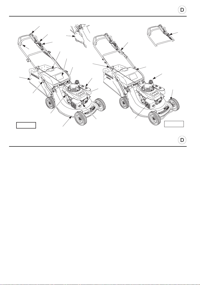
GRUNDLEGENDE ERKLÄRUNGEN
[3]
[2]
[19]
[1]
[4]
[13]
[14]
[B]
[A]
[11]
[6]
[1]
[15]
[17]
[5]
[10]
[16]
[9]
[8]
HRD536
[7]
[18]
BEZEICHNUNG DER BAUTEILE
BAUTEILE FUNKTION
1 Fahrgeschwindigkeits-Einstellhebel * . . . . . . . Zur Wahl der Fahrgeschwindigkeit
2 Gashebel . . . . . . . . . . . . . . . . . . . . . . . . . . . . . Zur Motordrehzahlregelung
3 Messerkupplungshebel (Rotostop) . . . . . . . . . Startet und bremst di e Drehung des Messers
4 Fahrantriebshebel
5 Einfüllstutzen für den Kraftstoff
6 Luftfilter
7 Zünkerzenstecker
8Auspuff
9 Öleinfüllstutzen mit Peilstab. . . . . . . . . . . . . . . Zum Auffüllen und Prüfen des Motorölpegels sowie den
10 Kraftstoffhahn . . . . . . . . . . . . . . . . . . . . . . . . . Zum Öffnen und Schließen der Bezinzufuhr
11 Griff des Starterseilzugs. . . . . . . . . . . . . . . . . . Handstarten des Motors
12 Hebel zur Einstellung der Schnitthöhe. . . . . . . Zur Wahl der gewünschten Schnitthö he
13 Grassack . . . . . . . . . . . . . . . . . . . . . . . . . . . . . Sammelt das geschnittete Gras
14 Griff des Einfüllsackes. . . . . . . . . . . . . . . . . . . Ablage und Leeren des Grassackes
15 Lenkgestänge
16 Höheneinstellung des Lenkgestänges *. . . . . . Zur Anpassung der Lenkgestängehöhe an die
17 Auswurfdeckel . . . . . . . . . . . . . . . . . . . . . . . . . Verhindert dem Austritt von Fremdkörpern
18 Messergehäuse
19 Hintere Rolle *
* Für die damit ausgerüsteten Modell e
14
Ölwechsel
Personengröße des Benutzers
[12]
HRH536
Page 15

EQUIPMENT IDENTIFICATION
CONTROLS FUNCTIONS
1 Shift lever *. . . . . . . . . . . . . . . . . . . . . . . . . . .
2 Throttle control lever. . . . . . . . . . . . . . . . . . . .
3 Cutter blade clutch lever (Rotostop safety) . .
4 Drive clutch lever
5 Fuel filler cap
6 Air cleaner
7 Spark plug cap
8 Muffler
9 Oil filler gauge-cap. . . . . . . . . . . . . . . . . . . . .
10 Fuel shut-off valve . . . . . . . . . . . . . . . . . . . . .
11 Recoil starter grip. . . . . . . . . . . . . . . . . . . . . .
12 Cutting height adjuster . . . . . . . . . . . . . . . . . .
13 Grass bag. . . . . . . . . . . . . . . . . . . . . . . . . . . .
14 Grass bag handle. . . . . . . . . . . . . . . . . . . . . .
15 Handle
16 Handle height adjustment system * . . . . . . . .
17 Discharge guard. . . . . . . . . . . . . . . . . . . . . . .
18 Cutter blade housing
19 Rear roller *
* Where fitted
GENERAL DESCRIPTION
Selects the forward speed
Adjusts the speed of the engine
Starts and stops the blade rotating
For filling and checking the engine oil levelFor draining the engine
oil
Opens and closes the fuel inlet
Manual engine starting
Selects the desired height of cut
Collects the cut grass
Removal and emptying of the grass bag
Adjusts the height of the handle to suit the height of the user
Prevents hard objects being thrown by the blade
DESCRIPTION GÉNÉRALE
IDENTIFICATION DU MATÉRIEL
COMMANDES FONCTIONS
1 Levier de changement de vitesse d’avancement * . Sélectionne la vitesse d’avancement
2 Levier de commande des gaz. . . . . . . . . . . . . . . . . Règle la vitesse du moteur
3 Levier d’embrayage de lame (sécurité Rotostop). . Démarre et freine la rotation de lame
4 Levier d’embrayage d’avancement
5 Bouchon de remplissage du carburant
6 Filtre à air
7 Capuchon de la bougie d’allumage
8 Pot d’échappement
9 Bouchon-jauge de remplissage d’huile . . . . . . . . . . Permet le remplissage et le contrôle du niveau d’huile
moteur et la vidange d’huile moteur
10 Robinet de carburant . . . . . . . . . . . . . . . . . . . . . . . Ouvre et ferme l’arrivée d’essence
11 Poignée du lanceur à retour automatique. . . . . . . . Mise en marche manuelle du moteur
12 Leviers de réglage de la hauteur de coupe. . . . . . . Sélectionne la hauteur de coupe souhaitée
13 Sac de ramassage . . . . . . . . . . . . . . . . . . . . . . . . . Collecte l’herbe coupée
14 Poignée du sac de ramassage . . . . . . . . . . . . . . . . Dépose et vidage du sac à herbe
15 Guidon
16 Système de réglage de hauteur du guidon *. . . . . . Ajuste la hauteur du guidon à la taille de l’utilisateur
17 Protecteur de décharge. . . . . . . . . . . . . . . . . . . . . . Évite les projections
18 Carter de lame
19 Rouleau arrière *
* Pour les modèles équipés
15
Page 16
GRUNDLEGENDE ERKLÄRUNGEN
B
[10]
[11] [12]
[13]
A
1 23 4 5
6
7
8
9
Honda France Manufacturing S.A.S.
Rue des Châtaigniers - Pôle 45
45140 Ormes France
[14]
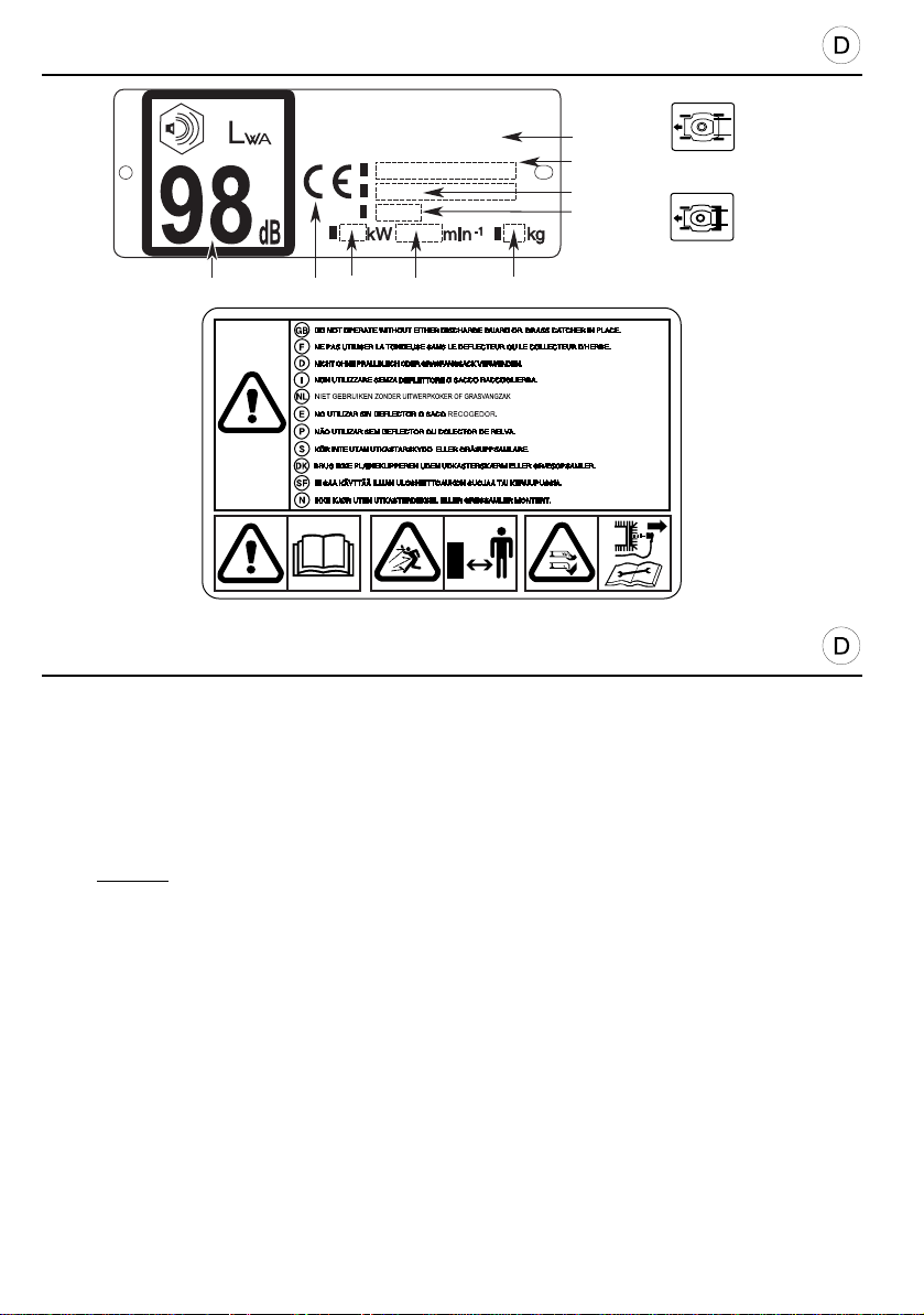
BESCHREIBUNG DER SICHERHEITSHINWEISE
Bitte seien Sie bei der Benutzung Ihres Rasenmähers vorsichtig. Aus diesem Grund haben wir
am Gerät Symbole angebracht, die Sie die au f wichtigsten Vorsichtsmaßnahmen hinweisen.
Die Bedeutung der Symbole ist unten erklärt.Diese Aufkleber sind als Teil des Mähers zu
betrachten. Sollte eines davon nicht angebracht oder nicht deutlich lesbar sein, setzen Sie sich
bitte zwecks Ersatz mit Ihrem Honda-Händler in Verbindung. Wir weisen auch noch einmal
ausdrücklich auf die Sicherheltsanweisungen hin, die Sie im nächsten Kapitel der
Bedienungsanleitung finden.
[10] Warnung: leser Sie vor dem Benutzen des Mähers die Bedienungsanlei tung genau dur ch.
[11] Gefährdung von Personen. Be Betr ieb Dritt e vom Gefa hrenbereich f ernhalt en.
[12] Verletzungsgefahr. Gefahr durch umlaufende Schneidwerkzeuge. Hände und Füße fernhalten. Entfernen Sie den
Zündkersenstecker vor allen Wartungs oder Re paratur arbeiten.
ERKLÄRUNG DER IN DIESER BEDIENUNGSANLEITUNG VERWENDETEN SYMBOLE
[13] Modelle mit vier Rädern [14] Modelle mit hinterer Rolle
TYPENSCHILD DER MASCHINE
1. Geräuschpegel nach Richtlinie 2000/14/EC 6. Herstellungsjahr
2. Konformitätskennzeichnung nach geänderter Richt linie 89/ 392/EWG 7. Seriennummer
3. Nennleistung 8. Modelle - Typenbezeichnung
4. Motordrehzahl in Umdrehungen pro Mi nute 9. Name und Anschrift des
5. Gewicht in Kilogramm Herstellers
16
Page 17

GENERAL DESCRIPTION
SAFETY LABEL LOCATIONS
Your lawn mower must be used with care. Therefore, decals have been placed on the machine,
to remind you pictorially of main precautions to take during use. Th eir meaning is explained
below.These decals are considered as a part of the mower. Sh ould one become detache d or
unreadable, contact your Honda dealer for its replacement.
[10] Warning: read the owner’s manual before using the mowe r.
[11] Risk of projections: Keep third persons away f rom the ar ea during use.
[12] Risk of cuts. Rotating blade: Do no t put hands o r feet in side the bl ade encl osure. Discon nect the spark plu g cap
before performing any operation of maintenance or repairs.
DESCRIPTION OF THE SYMBOLS USED IN THIS MANUAL
[13] Four wheels models [14] Rear roller models
IDENTIFICATION OF THE MACHINE
1. Acoustic power level according to the Directive 20 00/14/EC 6. Year of manufacture
2. Conformity mark, according to the 89/392 /EEC modif ied Directive 7. Serial number
3. Nominal power in kilowatt 8. Model - Type
4. Recommended engine speed in rpm 9. Name and address of the manufacturer
5. Mass in kilograms
DESCRIPTION GÉNÉRALE
EMPLACEMENT DES ÉTIQUETTES DE SÉCURITÉ
Votre tondeuse doit être utilisée avec prudence. Dans ce but, des étiquettes destinées à vous
rappeler les principales précautions d’utilisation ont été placées sur la machine sous forme de
pictogrammes. Leur signification est donnée ci-dessous.
Ces étiquettes sont considérées comme partie intégrante de la tondeuse. Si l’une d’entre elles
se détache ou devient difficile à lire, contactez votre concessionnaire pour la remplacer.
Nous vous recommandons également de lire attentivement les consignes de sécurité données
au chapitre suivant du présent manuel.
[10] Attention : lire le manuel d’utilisateur avant utilisation.
[11] Risque de projection. Tenir les tierces personnes en dehors de la zone pendant l’utilisation.
[12] Risque de coupure. Lame tournante. Ne pas int roduire les main s et pieds dans l’e nceinte de la me.
Débrancher le capuchon de bougie avant toute op ération d’e ntretien ou de réparati on.
EXPLICATION DES SYMBOLES UTILISÉS DANS LE MANUEL
[13] Modèles à 4 roues [14] Modèles à rouleau arrière
IDENTIFICATION DE LA MACHINE
1. Niveau sonore selon directive 2000/14/ EC 6. Année de fabrication
2. Marquage de conformité, selon directi ve 89/392 /CEE mod ifiée 7. Numéro de série
3. Puissance nominale 8. Modèle - Type
4. Vitesse d’utilisation du moteur en tours p ar minute 9. Nom et adresse du constructeur
5. Masse en kilogrammes
17
Page 18
VORBEITUNGEN UND KONTROLLEN VOR INBETRIEBNAHME
[1]
[3]
[2]
[3]
[6]
[7]
[5]
[4]
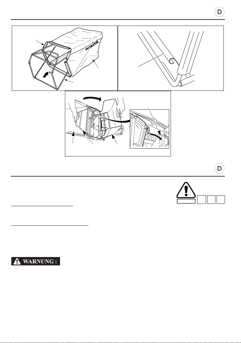
KONTROLLE DES GRASSACKS
1. Den Rahmen [1] wie gezeigt in den Grassack [2] einsetzen.
2. Die Plastikführungen [3] des Grassacks am Rahmen einhängen.
Abnehmen des Grassacks:
1. Motor stoppen.
2. Deckel [4] anheben, Sackbügel [5] greifen und Sack nach hinten abziehen.
Wiedereinhängen des Grassacks:
1. Deckel anheben und Sackvorderteil [7] in die Nocken [6] am Rasenmäher einhängen.
2. Der Rasenmäher arbeitet ähnlich wie ein Staubsauger: die Propellerform der Messerklinge
erzeugt einen Luftstrom, der das Schnittgut in den Sack bläst. Für gute Leistung ist es daher
wichtig, daß die Maschen der Sackwände nicht mit Gras und Erde verstopft sind.
Vor der Inbetriebnahme sollten.
Sie sich vergewissern, daß der Auswurfdeckel auf dem Sack richtig aufliegt. Der
Grasfangsack unterliegt auch bei normalem Betrieb einem gewissen Verschleiß. Wenn
ein Sack anfängt auszufransen oder Löcher zu bekommen, muß er durch einen neuen
Original Honda Sack ersetzt werden.
SICHERHEIT
C11 C20 D6
18
Page 19
C11 C20 D6
PREPARATIONS AND CHECKS BEFORE USE
CHECKING OF THE GRASS BAG
1. Insert the bag frame [1] into the grass bag [2], as shown.
2. Hook the plastic edges [3] of the grass bag onto the frame.
Bag removal:
1. Stop the engine.
2. Raise discharge guard [4], grasp handle [5] and remove bag while keeping it in an upright
position.
Bag fitting:
1. Raise the discharge guard and hook the front of the bag [7] on the mower’ s attachment
lugs [6].
2. Once the bag is fitted, the mower operates like a vacuum cleaner. It forces air into the bag
which traps the grass cuttings.
Before use, make sure that the discharge guard is hard against the bag.
Even in normal use, the grass bag tends to wear. Regularly check that it is not frayed or
torn. A worn out bag must be replaced. Replace a damaged bag by a Honda bag only.
SAFETY
C11 C20 D6
PRÉPARATIONS ET VÉRIFICATIONS AVANT UTILISATION
VÉRIFICATION DU SAC DE RAMASSAGE
1. Monter le sac [2] sur le cadre du sac de ramassa ge [1], comme
illustré.
2. Accrocher les rebords en plastique [3] du sac de ramassage
sur le cadre.
Retrait du sac :
1. Arrêter le moteur.
2. So ulever le protecteur de décharge [4], saisir la poignée [5] et retirer le sac, tout en le
maintenant à la verticale.
Remise en place :
1. Soulever le protecteur de décharge et accrocher la partie avant du sac [7] sur les ergots [6]
de fixation de la tondeuse.
2. Une fois le sac installé, la tondeuse à gazon fonctionne comme un aspirateur. Elle projette
de l’air dans le sac qui emprisonne les brins d’herbe.
S’assurer avant utilisation, que le protecteur de décharge est bien bloqué sur le sac.
Même dans des conditions normales d’utilisation, le sac de ram assage a tendance à
s’user. Il convient donc de vérifier régulièremen t s’il n’est pas effiloché ou déchiré. Un
sac usé doit être remplacé. Ne remplacer un sac détérioré que par un sac Honda.
SECURITE
19
Page 20
VORBEITUNGEN UND KONTROLLEN VOR INBETRIEBNAHME
B3
[2]
[1]
Zur Ausführung dieser Arbeiten stellen Sie bitte den Rasenmäher auf
horizontalen, festen und grasfreien Boden. Zur Sicherheit ziehen Sie den
Zündkerzenstecker ab.
SICHERHEIT
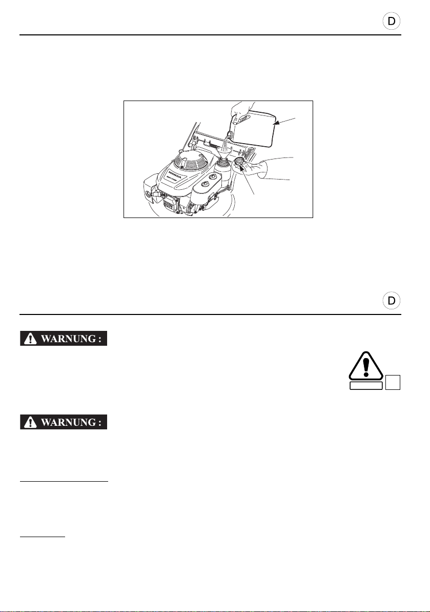
BEFÜLLEN DES KRAFTSTOFFTANKS
Kraftstofftank nie ganz vollfüllen. Im Einfüllstutzen darf sich kein Benzin befinden. Nach
dem Füllen Tankverschluß bis zum Anschlag aufschrauben.
Hände oder andere Körperteile nicht länge r mit Benzin benetzen, Benzindämpfe nicht
einatmen, Kinder fernhalten, nicht rauche n.
Benzinstandkontrolle:
1. Tankverschluß [1] abschrauben und Benzinstand kontrollieren.
2. Falls nötig, nachfüllen [2].
3. Tankverschluß [1] sorgfältig schließen.
Tankinhalt:
20
1,5 liter.
Page 21
SECURITE
B3
PREPARATIONS AND CHECKS BEFORE USE
SAFETY
B3
To carry out this series of checks, place the mowe r on stable and level
ground with engine stopped and s park plug cap removed.
CHECKING FUEL LEVEL
Do not fill the fuel tank up to the brim (there must be no fuel in the filler neck). When filling
is completed, ensure that the tank filler cap is screwed fully on.
Avoid getting fuel on the skin repeatedly or for long periods and avoid breath ing fuel
vapours. Keep fuel away from children.
To check the fuel level:
1. Remove filler cap [1] and check fuel level.
2. Fill [2] tank if level is low.
3. Screw filler cap [1] fully on after filling.
Fuel tank capacity:
1.5 litres.
PRÉPARATIONS ET VÉRIFICATIONS AVANT UTILISATION
Pour réaliser cette série de vérifications, placer la tondeuse su r un sol
stable et de niveau, le moteur étant à l’arrêt et le c apuchon de la bougie
d’allumage retiré de la bougie.
VÉRIFICATION DU NIVEAU D’ESSENCE
Ne pas remplir à ras bord le réservoir d’essence (il ne doit pas y avoir d’essence dans le
col de remplissage). Une fois le remplissage terminé, s’assurer que le bouchon du
réservoir est vissé correctement et à fond.
Éviter tout contact répété ou prolongé d’essence avec la peau ainsi que toute inhalation
de vapeurs d’essence. Ne pas laisser d’essence à la portée des enfants.
Pour vérifier le niveau d’essence :
1. Dévisser le bouchon [1] et contrôler le niveau d’essence.
2. Remplir [2] le réservoir si le niveau est bas.
3. Revisser le bouchon [1] à fond après remplissage.
Contenance du réservoir d’essence :
1,5 litres.
21
Page 22
VORBEITUNGEN UND KONTROLLEN VOR INBETRIEBNAHME
VORSICHT:
VORSICHT:
[1]
[2]
[3]
[4]
KRAFTSTOFFE
Nutzen Sie nur unverbleiten Kraftstoff (minimum 86 Oktan).
• Benutzen Sie niemals Kraftstoff der:
- verschmutzt ist,
- mehr als 30 Tage gelagert wurde,
- alkohol enthält (Ethanol oder Methanol),
- mit Öl vermischt wurde (z.B. 2-Takt Gemisch).
• Achten Sie darauf, dass weder Wasser noch Schmutz in den Kraftstofftank gelangen kann.
ZUR BEACHTUNG: Beschädigungen oder Leistungsprobleme des Motors, die auf
ungeeigneten Kraftstoff bzw. Kraftstoff von schlechter Qualität zurückzuführen sind, sind von
der Garantie ausgeschlossen.
KONTROLLE DES LUFTFILTERS
• Den Motor nie ohne Luftfilter betreiben! Dies würde zu schnellem Verschleiß von Kolben und
Zylinder führen.
Kontrolle des Luftfilters:
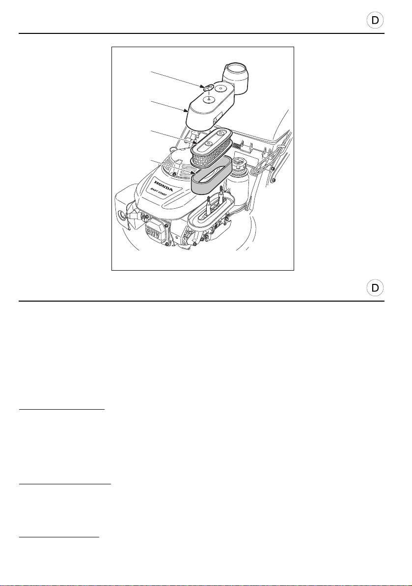
1. Entfernen Sie die Flügelmuttern [1] und die Abdeckung [2].
2. Filterelement [3] und [4] auf Sauberkeit prüfen. Schmutzige Filter säubern. (Im Kapitel
"Wartung" finden Sie dazu Hinweise).
3. Bauen Sie die Abdeckung [2] wieder an und befestigen Si die Flügelmuttern [1].
ZUR BEACHTUNG:
bleibt sie nicht in Position und das Gerät arbeitet nicht einwandfrei. Der Motor würde dann nicht
mehr korrekt funktionieren.
22
Falls die Flügelmuttern der Abdeckung nicht korrekt angezogen werden,
Page 23

PRÉCAUTION :
PRÉCAUTION :
PREPARATION AND CHECKS BEFORE USE
CAUTION:
CAUTION:
GASOLINE
Use only unleaded gasoline (octane minimum rate : 86).
• Do not use gasoline if it is:
- dirty,
- stored for more than 30 days,
- containing alcohol (ethanol or methanol),
- gasoline mixed with oil (2 stroke mixture).
• Do not allow dirt or water to enter to fuel tank.
Any damage or engine performance troubles resulting from inappropriate or bad quality
NOTE:
gasoline usage will not be covered by warranty.
CHECKING THE AIR CLEANER
• Never run the engine without the air clea ner fitted since th is could cause premature engine
wear.
To check the condition of the air cleaner:
1. Remove wing nuts [1] and cover [2].
2. Check the cleanliness of filter elements [3] and [4]. If the elements are dirty, follo w the
cleaning procedure (see Maintenance chapter).
3. Refit cover [2] and wing nuts [1].
After cleaning the air cleaner element, replace cover and push fully home. It the cover
NOTE:
wing nuts are not correctly tightened, the cover will not remain in place and the engine will not
operate correctly.
PRÉPARATION ET VÉRIFICATIONS AVANT UTILISATION
CARBURANT
Utiliser de l’essence automobile sans plomb (indice d’octane 86 minimum).
• Ne pas utiliser d’essence :
- sale,
- ayant plus de 30 jours de stockage,
- contenant de l’alcool (éthanol ou méthanol),
- Mélangée à de l’huile (mélange pour moteur 2 temps).
• Ne pas laisser pénétrer de saletés ou d’eau dans le réservoir.
NOTE : Tout dommage ou baisse de performance du moteur résultant de l’utilisation d’essence
inappropriée ou de mauvaise qualité ne sera pas couvert par la garantie de la machine.
VÉRIFICATION DU FILTRE À AIR
• Ne jamais faire tourner le moteur sans le filtre à air, car il pourrait s’ ensuivre une usure
prématurée du moteur.
Pour vérifier l’état du filtre à air :
1. Retirer les écrous papillon [1] et le couvercle [2].
2. Contrôler la propreté des éléments filtrants [3] et [4].
Si les éléments sont sales, suivre la procédure de nettoyage (voir chapitre Entretien).
3. Remonter le couvercle [2] et les écrous papillon [1].
Après avoir nettoyé l’élément du filtre à air, remettre le couvercle en place et le fermer
NOTE :
à fond. Si les écrous papillon maintenant le couvercle ne sont pas bien serrées, le couvercle
peut ne pas rester en place et provoquer un mauvais fonctionnement du moteur.
23
Page 24
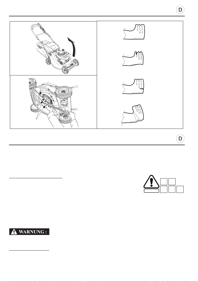
VORBEITUNGEN UND KONTROLLEN VOR INBETRIEBNAHME
VORSICHT:
SICHERHEIT
B3
B5
C18
D1 D8
[1]
[2]
[3]
[4]
[6]
[5]
[A]
KONTROLLE DES MESSERS
• Bitte kippen/legen Sie den Rasenmäher nicht auf die dem Vergaser zugewandte Seite. Dies
könnte Startschwierigkeiten verursachen, da Motoröl in den Luftfilter eindringen kann.
Zur Inspektion des Messers:
1. Stoppen Sie den Motor.
2. Ziehen Sie den Zündkerzenstecker ab.
3. Legen Sie den Mäher auf die Seite [A], so daß der Vergaser nach
oben zeigt (linke Seite).
• Das Messer [1] auf Abnutzung prüfen und falls erforderlich auswecheln.
• Befestigungsschrauben [2] des Messers auf festen Anzug prüfen.
• Für Ausbau und Erneuerung des Messers die Hinweise (im Kapitel Wartung beachten).
[3] NEUES MESSER [5] VERBOGEN MESSER
[4] ZU STARK ABGENUTZT MESSER [6] RISSIG MESSER
Rasenmäher nie mit abgenutztem oder beschädigtem Schneidwerkzeug betreiben.
Herausgeschleuderte Bruchstücke können sehr schwere Verletzungen verursachen.
ZUR BEACHTUNG:
Schneidwerkzeugkontrolle ist bei sandhaltigem Gelände angebracht.
24
Auf Sandboden ist die Messerabnutzung besonders groß, häufige
Page 25

PRÉCAUTION :
SECURITE
B3
B5
C18
D1 D8
PREPARATION AND CHECKS BEFORE USE
CAUTION:
B3
B5
C18
D1 D8
CHECKING BLADE CONDITION
• Do not tilt the mower with the carburettor facing down ; this wi ll make the mower difficul t to
start later, due to engine oil blocking the air cleaner.
To check blade condition:
1. Stop the engine.
2. Pull off the spark plug cap.
3. Place the mower on its side [A], so that the carburettor is facing
upwards (left side).
• Check if the blade [1] shows signs of wear or damage and replace it if necessary.
• Check that blade screws [2] are tightened (see Maintenance chapter).
• For blade replacement or removal/ installation, refer to the procedure descri bed in the
Maintenance chapter.
[3] NEW BLADE [5] BENT BLADE
[4] EXCESSIVELY WORN BLADE [6] CRACKED BLADE
Never operate the mower with a worn, damaged, split or dented blade.
A piece of blade which breaks off and is thrown outwards can cau se serious bodily
injuries.
Blade wear is increased when the mower is used on sandy soils. Inspect the blade more
NOTE:
often when the mower is used in these conditions.
SAFETY
PRÉPARATION ET VÉRIFICATIONS AVANT UTILISATION
VÉRIFICATION DE L’ÉTAT DE LA LAME
• Ne pas incliner la tondeuse avec le carburateur orienté ve rs le bas ; il en résulterait un
redémarrage très difficile par la suite, dû à l’obstruction du filtre à air par de l’huile moteur.
Pour vérifier l’état de la lame :
1. Arrêter le moteur.
2. Retirer le capuchon de la bougie d’allumage.
3. Mettre la tondeuse sur le côté [A], de telle sorte que le carburateur
soit orienté vers le haut (côté gauche).
• Vérifier si la lame [1] présente des signes d’usure et la remplacer, si c’est nécessaire.
• Vérifier le serrage des vis de lame [2] (voir chapitre Entretien).
• Pour remplacer la lame ou effectuer une dépose-repose, se référer à la procédure décrite
au chapitre Entretien.
[3] LAME NEUVE [5] LAME TORDUE
[4] LAME EXCESSIVEMENT USAGEE [6] LAME FENDUE
Ne jamais faire fonctionner la tondeuse avec une lame usée ou endommagée, fendue ou
entaillée.
Un morceau de lame qui se casse et se trouve projeté p eut être la cause de blessu res
graves.
NOTE :
sablonneux. Examiner très souvent la lame, en cas d’utilisation de la tondeuse dans ces
conditions.
L’usure de la lame est plus rapide, lorsque la tondeuse travaille sur des sols
25
Page 26
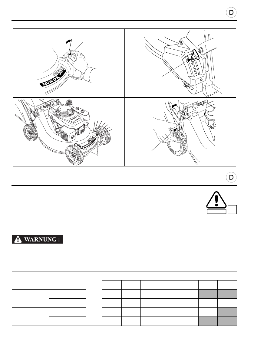
VORBEITUNGEN UND KONTROLLEN VOR INBETRIEBNAHME
[1]
[1]
QXE
HXE
[1]
[1]
HXE
SICHERHEIT
EINSTELLUNG DER SCHNITTHÖHE
Um die Höhe der Schnittebene zu verstellen:
1. Motor stoppen.
2. Die Einstellhebel [1] vorn und hinten nach aussen schieben und sie nach oben bzw. unten
drücken, um die Schnittebene höher oder tiefer einzustellen. Die Vorder- und Hinterräder
auf die gleiche Höhe einstellen.
Beim Einstellen der Höhe des rechten Vorderrades darauf achten, daß der
Schalldämpfer nicht berührt wird.
Die Höhenangaben sind Anhaltswerte. Die tatsächliche Schnitthöh e wird am besten durch
einen Mähversuch ermittelt, da sie von der Bodenbeschaffenheit und dem Rasen abhängt.
Stellung
26
Modellen Typen
HRD536
HRH536
QXE
HXE
HXE
QXE
1234567
14 21 30 41 52
14 21 30 41 52 64 76
in mm
Schnitthöhe
21 30 41 52 64 76
14 21 30 41 52
C20
Page 27
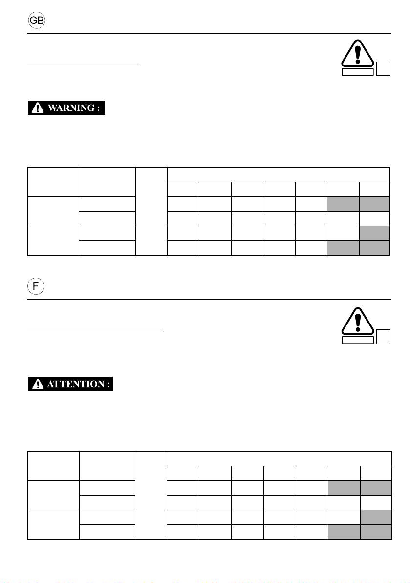
PREPARATION AND CHECKS BEFORE USE
SAFETY
SECURITE
ADJUSTING CUTTING HEIGHT
To change the cutting height:
1. Stop the engine.
2. Push the front and rear adjusting levers [1] towards the wheels and move them up or down
to raise or lower the cutting height. Adjust front and rear wheels to the same height.
Be careful not to touch the muffler when adjusting the right front wheel height.
The cutting height settings are approximate values, the actual height of the cut grass varies with
the lawn and ground condition. To choose th e cutting height, check how the lawn looks after
mowing a small area and adjust the cutting height where necessary.
C20
Models Types
Positions
1234567
HRD536
HRH536
QXE
HXE
HXE
QXE
Cutting height
14 21 30 41 52
14 21 30 41 52 64 76
in mm
21 30 41 52 64 76
14 21 30 41 52
PRÉPARATION ET VÉRIFICATIONS AVANT UTILISATION
RÉGLAGE DE LA HAUTEUR DE COUPE
Pour changer la hauteur de coupe :
1. Arrêter le moteur.
2. Pousser les manettes de réglage [1] avant et arrière vers les roues et les basculer vers le
haut ou le bas pour augmenter ou diminuer la hauteur de coupe. Régler les roues avant et
arrière à la même hauteur.
Prendre garde à ne pas toucher le pot d’échappement , lorsque l’on règle la hau teur de la
roue avant droite.
Les réglages de hauteur de coupe correspondent à des valeurs approximatives, la hauteu r
réelle de l’herbe coupée varie avec l’état de la pelouse et du sol. Pour choisir la hauteur de
coupe, vérifier l’aspect de la pelouse après avoir tondu une petite surface et, le cas échéant,
régler la hauteur de coupe.
Modèles Types
Positions
1234567
HRD536
HRH536
QXE
HXE
HXE
QXE
Hauteur de coupe
14 21 30 41 52
14 21 30 41 52 64 76
en mm
21 30 41 52 64 76
14 21 30 41 52
C20
27
Page 28
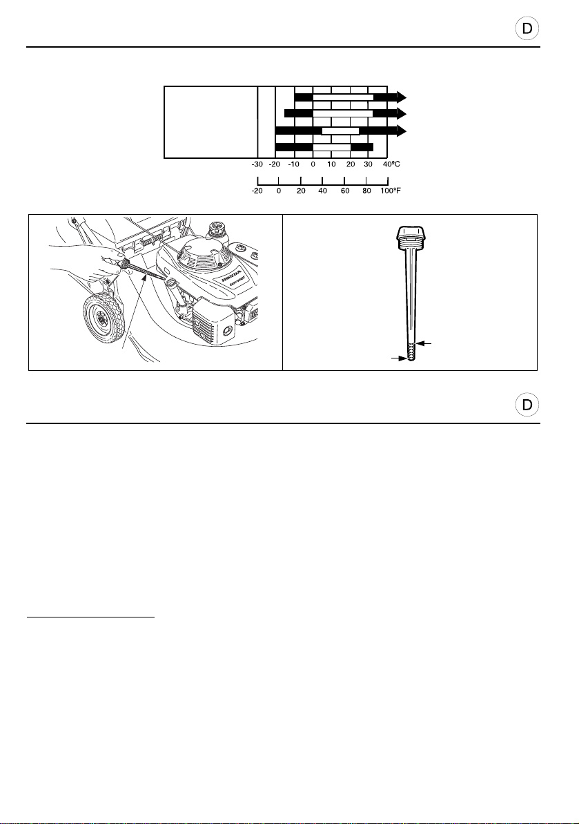
VORBEITUNGEN UND KONTROLLEN VOR INBETRIEBNAHME
VORSICHT:
15W40 15W50
10W40
20W40 20W50
10W30
[1]
[2]
[3]
[4]
[5]
ÖLSTANDKONTROLLE
• Das Motoröl beeinflußt die Leistung und Lebensdauer ihres Gerätes!
• Niemals den Motor ohne oder mit zu wenig Öl laufen lassen, dies verursacht schwere
Schäden am Motor. Verwenden Sie Original Honda Motoröl oder Markenöle für Viertakt
Motoren mit SAE-Viskosität 10W30. Den optimalen Viskositätsgrad finden Sie je nach
Lufttemperatur und Höhenlage des Rasengeländes aus vorheriger Tabelle.
[1] MEHRBEREICHSÖL
[2] UMBEDUNGSTEMPERATUR
Kontrolle des Ölstands:
1. Den Rasenmäher auf einen ebenen, horizontalen Boden stellen.
2. Öltankverschluß durch Links- drehung abschrauben, heraus- ziehen [3] und abwischen.
3. Meßstab wieder bis zum Anschlag in den Einfüllstutzen stecken, nicht einschrauben.
4. Meßstab herausziehen und in waagrechter Stellung den Ölstand ablesen. Der Ölspiegel
muß sich zwischen Maximum [4]- und Minimum [5]- Marke befinden. Vor Erreichen der
Minimummarke, Öl nachfüllen (siehe auch Wartungshinweise). Kontrolle durch
Wiederholung von 3. und 4. Nicht überfüllen!
5. Meßstab wieder in Einfüllstutzen stecken und mit Rechtsdrehung zuschrauben.
28
Page 29

PRÉCAUTION :
PREPARATION AND CHECKS BEFORE USE
CAUTION:
CHECKING ENGINE OIL LEVEL
• The engine oil is an essential element which affects the performance and lifetime of the
engine.
• The engine may be seriously damaged if run with insufficient oil. We recommend the use of
Honda 4-stroke oil or an equivalent quality engine oil which is highly detergent. Oil viscosity
must be appropriate for the average temperature in the zone where the mower is to be used.
[1] MULTIGRADE
[2] AMBIENT TEMPERATURE
To check engine oil level:
1. Put the lawn mower on flat, even ground.
2. Remove the oil filler cap and wipe the dipstick [3].
3. Replace the dipstick in the filler neck but do not screw it down.
4. Check the level of the oil left on the dipstick. If the level is near the low level mark [5], add the
recommended oil up to the high level mark [4].
5. Screw filler cap.
PRÉPARATION ET VÉRIFICATIONS AVANT UTILISATION
VÉRIFICATION DU NIVEAU DE L’HUILE MOTEUR
• L’huile moteur est un élément essentiel qui influe sur les perfo r mances du moteur ainsi que
sur sa durée de vie.
• Faire tourner le moteur avec une quantité d’huile insuffisante peut grave ment endommage r
ce dernier. Il est recommandé d’employer une huile Honda 4 temps ou encore une huile pour
moteur de qualité équivalente et ha utement détergente. Il convient de choisir la viscosité
appropriée à la température moyenne de la zone d’utilisation.
[1] MULTI GRADE
[2] TEMPERATURE AMBIANTE
Pour vérifier le niveau d’huile moteur :
1. Mettre la tondeuse sur un sol plan et horizontal.
2. Retirer le bouchon de remplissage d’huile et essuyer la jauge [3].
3. Remettre la jauge dans le goulot de remplissage, mais sans la visser.
4. Vérifier la marque du niveau d’huile laissée sur la jauge. Si cette de rnière est proche du
repère de niveau inférieur [5] rajouter l’huile préconisée jusqu’au repère de niveau
supérieur [4].
5. Revisser le bouchon de remplissage.
29
Page 30
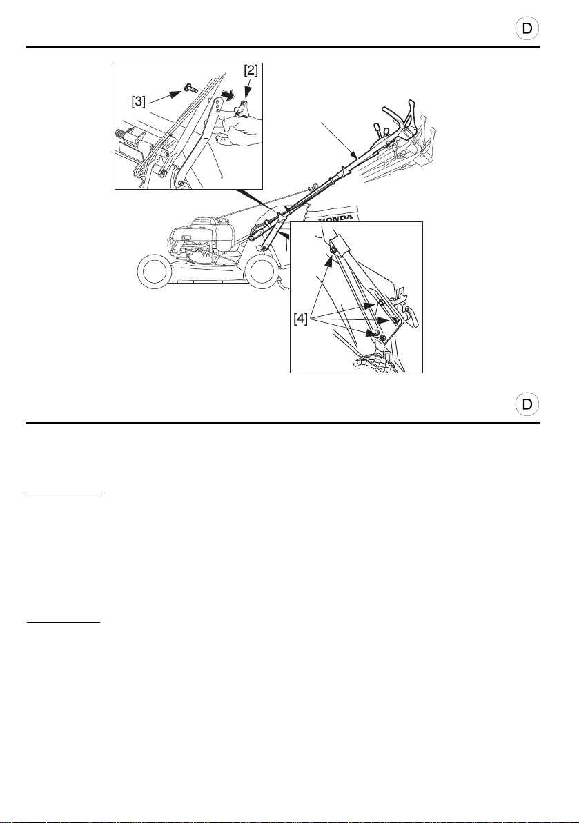
VORBEITUNGEN UND KONTROLLEN VOR INBETRIEBNAHME
HRD536
HRH536
[1]
HÖHENEINSTELLUNG DES LENKGESTÄNGES
Für HRD536:
Die Höhe des Lenkgestänges [1] kann in drei verschiedenen Positionen eingestellt
werden.Wählen Sie die Stellung, die für Sie am bequemsten ist und aufrechten,
ermüdungsfreien Gang ermöglicht.
1. Lösen Sie die Flügelmutter [2] entfernen Sie die Schraube [3] von der Höhenverstellung.
2. Stellen Sie den Handgriff auf die gewünschte Höhe ein.
3. Führen Sie die Schraube [3] in das entsprechende Loch auf d er Höhenverstellung ein.
Befestigen Sie die Flügelmutter [2].
Für HRH536:
Einstellung der Höhe des Bedlenerholmes für eine optimale Bedienung.
1. Lösen Sie die Halteschrauben [4] des Holmes auf belden Selten.
2. Stellen Sie den Holm nach lhren Bedürfnissen ein.
3. Überprüfen Sie, daß die Holm - Halteschrauben wieder korrekt angezogen wurden.
30
Page 31

PREPARATION AND CHECKS BEFORE USE
HANDLE HEIGHT ADJUSTMENT SYSTEM
For HRD536:
The height of the handle [1] can be adjusted to three positions. Choose the height which is most
comfortable for you.
1. Untighten the knob [2] remove the screw [3] from the adjustable support.
2. Present the handle at the desired height.
3. Engage the screw [3] in the corresponding hole on the adjusta ble supports. Tighten the
knob [2].
For HRH536:
Adjust handle height for convenient mowing.
1. Loosen both side of handle hook bolts [4].
2. Swing the handle up or down as required.
3. After adjusting, make sure the handle hook bolts are tightened securely.
PRÉPARATION ET VÉRIFICATIONS AVANT UTILISATION
SYSTÈME DE RÉGLAGE DE LA HAUTEUR DU GUIDON
Pour HRD536 :
La hauteur du guidon [1] est réglable suivant trois positions. Choisir la hauteur qui procure la
position la plus confortable.
1. Desserrer les poignées [2] du guidon pour dégager les vis de positionnement [3].
2. Présenter le guidon à la hauteur souhaitée.
3. Engager les vis de positionnement [3] dans le trou correspondant des supports réglages.
Resserrer les poignées [2].
Pour HRH536 :
Choisir la hauteur qui procure la position la plus confortable.
1. Desserrer les écrous [4].
2. Présenter le guidon à la hauteur souhaitée.
3. Après le réglage, s’assurer que les écrous de fixation sont suffisamment serrés.
31
Page 32
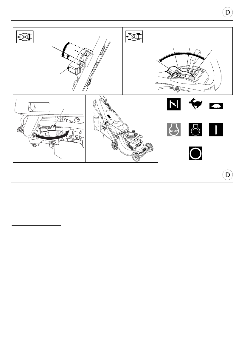
ANLASSEN UND ABSCHALTEN DES MOTORS
VORSICHT:
[2]
[9]
[4]
[5]
[7]
[3]
STOP
[4]
[1]
[5]
[6]
[5]
[4]
[1]
[6]
[6]
[8]
[10]
ANLASSEN DES MOTORS
• Motor niemals bei eingelegter Messer- oder Radkupplung starten! Zum Anlassen,
Rasenmäher auf ebene, grasfreie Fläche schieben.
1. Gashebel [1] in Stellung “CHOKE” [4] bringen.
ZUR BEACHTUNG: Bei warmem Motor (Wiederanlassen) oder an sehr heißen Tage n den
“CHOKE” nicht betätigen, sondern Gashebel gleich in Stellung “SCHNELL”[5] schieben.
[4] CHOKE: Anlassen des Kalten Motors. [7] STOPP: Motor Abstellung.
[5] SCHNELL: Anlassen des warmen Motors, Stellung für optimalen [8] STARTEN: Anstellen des Motors.
Mähbetrieb. [9] EIN: Motor läuft.
[6] LANGSAM: Für Leerlauf und zum Sackentleeren. [10] STOPP: Abstellen des Motors.
2. Den Kraftstoffhahn [2] öffnen.
3. Das Lenkgestänge fest mit einer Hand halten.
4. Ziehen Sie den Anlasserseilzug [3] langsam mit der anderen Hand, bis Sie einen
Widerstand spüren; ziehen Sie dann den Seilzug mit einem Ruck.
ZUR BEACHTUNG:
Hand zurück.
5. Wenn der Motor warmgelaufen ist, den Gashebel auf “SCHNELL” [5] stellen.
32
Lassen Sie den Seilzug nicht zurückfedern, sondern führen Sie ihn mit der
Page 33

PRÉCAUTION :
STARTING AND STOPPING THE ENGINE
CAUTION:
STARTING THE ENGINE
• Do not start the engine with the blade clutch lever or the drive clutch lever engaged.
1. Place the throttle control lever [1] in “CHOKE” position [4].
NOTE: Place the throttle control lever in “FAST” position [5] when the engine is hot or the
ambient temperature is high.
[4] CHOKE: For starting a cold engine. [8] START: Starting the engine.
[5] FAST: For restarting a hot engine and for mowing . [9] ON: Engine run.
[6] SLOW: Selects engine idling speed. [10] STOP: Engine off.
[7] STOP: Stops engine.
2. Turn the fuel shut-off valve [2].
3. Hold the handle firmly with one hand.
4. Pull the starter grip [3] slowly with the other hand until resistance is felt. Then pull the cord
rapidly.
Do not let the starter grip snap back ; return it by hand.
NOTE:
5. After the engine warms up move the throttle to “FAST” position [5].
MISE EN MARCHE ET ARRÊT DU MOTEUR
MISE EN MARCHE DU MOTEUR
• Ne pas démarrer le moteur les leviers d’embrayage de lame ou d’avancement engagés.
1. Mettre le levier de commande des gaz [1] sur la position “STARTER” [4].
NOTE :
levier de commande des gaz sur la position “RAPIDE” [5].
2. Ouvrir le robinet d’essence [2].
3. Maintenir fermement le guidon d’une main.
4. Tirer doucement le lanceur [3] de l’autre main, jusqu’à sentir une résistance ; puis tirer
NOTE :
5. Une fois que le moteur est chaud, mettre le levier de commande des gaz sur la position
Lorsque le moteur est chaud ou que la temp érature ambiante est élevée, mettre le
[4] STARTER : Démarrage à froid. [8] DEMARRAGE : Mise en marche du moteur.
[5] RAPIDE : Redémarrage d’un moteur chaud et tonte. [9] MARCHE : Marche du moteur.
[6] LENT : Mise au ralenti du moteur. [10] ARRÊT : Arrêt du moteur.
[7] ARRÊT : Arrêt du moteur.
vivement.
Ne pas laisser le lanceur revenir seul brutalement ; le ramener à la main.
“RAPIDE” [5].
33
Page 34
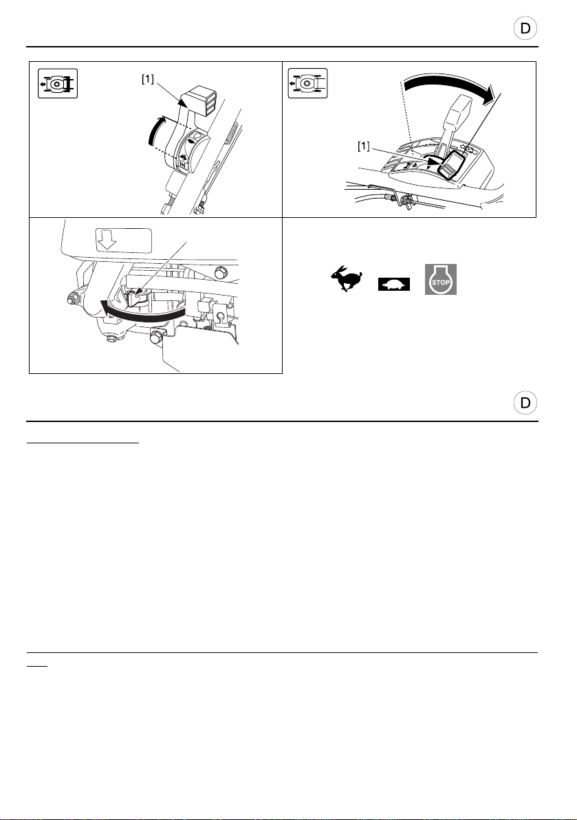
ANLASSEN UND ABSCHALTEN DES MOTORS
S
TOP
[2]
[A]
[B]
[C]
ZUR BEACHTUNG:
• Zur Drehzahlregelung kann der Gashebel in jede beliebige Stellung zwischen
“SCHNELL” [5] un d “LANGSAM” [6] gebracht werden. Für gleich- mäßigen Schnitt und bei
hohem Gras ist die Stellung “SCHNELL” [5] zu empfehlen. Bei angekoppeltem
Messerantrieb und schlecht eingestelltem Vergaser kann der Motor in Stellung
“LANGSAM” [6] eventuell stehenbleiben (Vergaser einstellen).
ABSTELLEN DES MOTORS
1. Den Gashebel [1] auf die Position “STOPP” [C] bringen.
2. Den Benzinhahn schließen [2].
“ABGESOFFENER” MOTOR
Wenn der Motor nach mehrmaligen Anlaßversuchen nicht anspringt, besteht die
Wahrscheinlichkeit, daß er infolge unverbrannten Treibstoffs in Vergaser und Zylinder
“ertrunken” ist.
In diesem Fall sieht man zuerst nach, ob nicht eventuell der Tank leer ist und geht dann wie folgt
vor:
1. Den Gashebel [1] auf die Position “STOPP” [C] bringen.
2. Kerzenstecker abziehen, Zündkerze mit Zündkerzenschlüssel ausbauen und trocknen.
Gereinigte oder neue Kerze ohne Gewalt bis zum Anschlag von Hand eindrehen, danach
mit Schlüssel 1/8 bis 1/4 Drehung festziehen, um den Kerzendichtring zu komprimieren.
Kerzenstecker aufsteken.
3. Anschließend den Gashebel auf die Position “SCHNELL” [A] bringen und die im
vorausgegangenen Abschnitt “Anstellen des Motors”, Seite 32, § 2, 3, 4 und 5, genannten
Schritte wiederholen.
34
Page 35

STARTING AND STOPPING THE ENGINE
NOTE:
• To adjust the engine speed when the mower is runnin g, the throttle control lever can be set
anywhere between the “FAST” [5] and “SLOW” [6] positions. However, the best results are
obtained in the “FAST” position [5].
• The engine may stall if the lever is in the “SLOW” [6] position when the blade clutch is
engaged.
• To facilitate starting, place the mower on a flat surface where the grass is not long.
STOPPING THE ENGINE
1. Put the throttle control lever [1] in the “STOP” position [C].
2. Close the fuel shut-off valve [2].
FLOODED ENGINE
If the engine still refuses to start after several pulls on the starter, the engine may be flooded.
To clear a flooded engine:
1. Place the throttle control lever in “STOP” position [C].
2. Remove and dry the spark plug. When refitting the spark plug, screw it up until it is finger
tight and correctly seated. Then using the plug spanner, tighten it an additional 1/8 to 1/4
turn so that the washer is correctly compressed.
3. Then put the throttle control lever in the “FAST” position [A] and repeat the previous
operations mentioned under the heading “Starting the engine”, page 33 § 2, 3, 4, and 5.
MISE EN MARCHE ET ARRÊT DU MOTEUR
NOTE :
• Pour régler la vitesse du moteur au cours du fonctionnement de la tondeuse, le levier de
commande des gaz peut être positionné n’importe où entre les positions “RAPIDE” [5] et
“LENT” [6]. On obtient cependant de meilleurs résultats sur la position “RAPIDE” [5].
• Le moteur peut caler si le levier est sur la position “LENT” [6], lors de l’engagement de
l’embrayage de lame.
• Pour faciliter le démarrage, placer la tondeuse sur une surface plane, sans he rbe haute.
ARRÊT DU MOTEUR
1. Placer le levier de commande des gaz [1] sur la position “ARRÊT” [C].
2. Fermer le robinet d’arrivée d’essence [2].
MOTEUR NOYÉ
Si le moteur refuse toujours de démarrer après plusieurs tractions exercées sur le lanceur, il se
peut alors qu’il soit noyé.
Pour désengorger un moteur noyé :
1. Placer le levier de commande des gaz sur la position “ARRÊT” [C].
2. Retirer et sécher la bougie d’allumage. Lorsque l’on remet la bougie en place, la visser à la
main jusqu’à ce qu’elle soit en appui. Puis, avec la clé à bougie, la serrer d’1/8 à 1/4 de tour
supplémentaire pour bien comprimer la rondelle.
3. Mettre ensuite le levier de commande des gaz sur la position “RAPIDE” [ A] et répéter les
opérations précédentes mentionnées à la rubrique “Mise en marche du moteur”, page 33 §
2, 3, 4 et 5.
35
Page 36
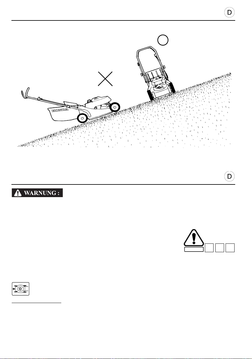
EMPFEHLUNGEN FÜR DEN BETRIEB
VORSICHT:
C8
C7C6
[1]
[2]
An Hängen ist Vorsicht geboten! Der Rasenmäher kann umkippen und die dann frei
rotierende Messerklinge kann Steine, Holzstücke u.s.w. ausschleudern.
Griffe daher fest anfassen und Gerät sicher führen.
Am Hang den Rasenmäher niemals mit dem Fuß lenken!
• Beim Umfahren von Hindernissen genügend Abstand halten. Nie
absichtlich über einen harten Gegenstand fahren.
• Beim Mähen mit Radantrieb auf hügeligem Gelände immer das
Gerät führen und sich nicht von ihm ziehen lassen!
[1] UNGÜNSTIG
[2] GUT
SICHERHEIT
ZUR BEACHTUNG: Falls die Einstellung der Geschwindigkeit für das Mähen am H ang zu
niedrig ist, kann der Schalthebel leicht in Richtung auf Position “SCHNELL” bewegt werden.
36
Page 37
PRÉCAUTION :
C8
C7C6
OPERATING HINTS AND TIPS
CAUTION:
SAFETY
C8
C7C6
Take special care when mowing on uneven or irregular ground. The mower may tip over,
thus uncovering the blade ; also, the blade may throw out objects which were previously
hidden.
Keep the four wheels firmly on the ground.
Control the direction of the mower using the hand le and not by exerting pres sure on the
blade housing with your foot.
• When mowing around an obstacle, be careful that the blade does not
hit it. Never push the mower directly over an object.
• When mowing an uneven area, do not let yourself be pulled along by
the mower. Hold the handle firmly and control its advance.
[1] WRONG
[2] RIGHT
If the lawn mower speed is too low when cutting on a slope, move the shift lever slightly
NOTE:
towards the “FAST” position.
CONSEILS D’UTILISATION
Il convient d’être particulièrement pruden t, lorsque l’on tond un sol au relief accidenté et
irrégulier. La tondeuse peut alors se renverser, metta nt ainsi la lame à découvert ; en
outre, la lame risque de projeter des objets demeurés jusqu’alors cachés.
Bien maintenir les quatre roues au sol.
Contrôler la direction de la tondeu se p ar l e guidon et non pas par une pression du pie d
sur le carter de la lame.
• Lorsque l’on doit contourner un obstacle, prendre ga rde à ne pas le
heurter avec la lame. Ne jamais passer la tondeuse délibérément sur
un objet.
• Lorsque l’on tond une surface au relief accidenté, ne pas se laisser
tirer par la tondeuse, maintenir fermement le guidon de la tondeuse
SECURITE
et surveiller sa progression.
.
[1] MAUVAIS
[2] BON
NOTE :
Si la vitesse de la tondeuse est trop réduite lorsque l’on tond sur une pente, déplacer
légèrement le levier de changement de vitesse vers la position “RAPIDE”.
37
Page 38
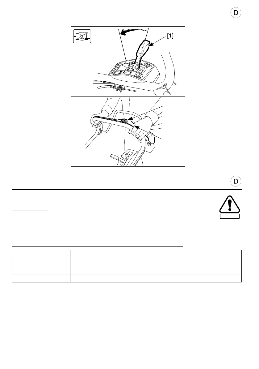
EMPFEHLUNGEN FÜR DEN BETRIEB
VORSICHT:
SICHERHEIT
[2]
[3]
BEDIENUNG DER STELLTEILE
Sicherheitsempfehlungen bitte vor Beginn der Arbeit durchlesen!
Um zu mähen:
1. Rasenmäher auf horizontales, ebenes Gelände ohne Gras bringen.
2. “STARTER” Position verlassen und Gashebel auf “SCHNELL” stellen. Bei damit
ausgerüsteten Rasenmähern, Messerkupplung einlegen.
3. Einstelle n der g ewünschte n Fahrge schwindigk e it mit Hilfe des Schaltheb els [1] (außer bei
den Ausführungen QXE).
Follgende Geschwindlgkeiten lassen sich bei Vorwärstfahrt einstellen:
Modellen Typen 1. Mini Maxi
HRD536 HXE - 0 1,4 m/s
HRD536 / HRH536 QXE 1,2 m/s - -
HRH536 HXE - 0,8 m/s 1,4 m/s
4. Das Messer einkuppeln: auf den gelben Knopf [2], der sich oberhalb des
Messerkupplungshebels [3] befindet.
• Mit einer schnellen und kräftigen Bewegung auf den Messerkupplungshebel [3] drücken,
damit das Messer immer entweder vollständig ein- oder ausgekuppelt ist. Dies verhindert, daß der
Motor abwürgt und verlängert die Lebensdauer des Messerkupplungsmechanismus. Der
Messerkupplungshebel und der Fahrantriebshebel müssen immer losgelassen werd en, bevor der
Motor gestartet wird. Sobald der Messerantrieb eingekuppelt ist, ist das Starten wenig er einfach.
Wenn der Fahrantrieb eingekuppelt ist, bewegt sich der Rasenmäher beim Starten vorwärts.
38
Page 39
PRÉCAUTION :
OPERATING HINTS AND TIPS
CAUTION:
CONTROLS AND MOWING PROCEDURES
Read the safety instructions before starting to mow.
To mow:
1. Place the mower in an obstacle free area.
2. Start the engine, allow it to reach its maximum temperature and rotation speed. (The engine
runs evenly when the throttle control lever is moved away from the “CHOKE” position).
3. Select the required forward speed using the shift lever [1] (except type QXE).
The following forward speeds are available:
Models Types 1st. Mini Maxi
HRD536 HXE - 0 1.4 m/s
HRD536 / HRH536 QXE 1.2 m/s - -
HRH536 HXE - 0.8 m/s 1.4 m/s
4. Engage the blade: press the yellow button [2] situated on the top of the blade clutch lever [3].
• Move the blade clutch lever [3] quickly and completely so that the clutch is always totally
engaged or disengaged. The purpose of this is to avoid stalling the engine and prolongs the
lifetime of the blade clutch mechanism. Always release the blade clutch lever and the drive
clutch before starting the engine. When the blade drive is engaged, starting is not as easy. If
the drive clutch is engaged, the lawn mower moves when started.
SAFETY
CONSEILS D’UTILISATION
COMMANDES ET PROCÉDURE DE TONTE
Lire les consignes de sécurité avant de commencer à tondre.
Pour tondre :
1. Placer la machine sur une zone libre de tout obstacle.
2. Démarrer le moteur, le laisser attein dre sa temp érature et son régime maxima l
(son fonctionnement est régulier lorsque l’on retire le starter).
3. Sélectionner la vitesse d’avancement voulue à l’aide du levier de changement de vitesse [1]
(sauf type QXE).
On dispose des vitesses d’avancement suivantes :
Modèles Types 1ère Mini Maxi
HRD536 HXE - 0 1,4 m/s
HRD536 / HRH536 QXE 1,2 m/s - -
HRH536 HXE - 0,8 m/s 1,4 m/s
4. Embrayer la lame : appuyer sur le bouton jaune [2] situé sur le dessus du levier
d’embrayage de lame [3].
• Exercer un mouvement rapide et complet sur le levier d’embrayage de lame [3] pou r
que l’embrayage soit toujours totalement engagé ou arrêté. Ceci a pour but d’éviter de caler
le moteur et permet de prolonger la durée de service du mécani sme d’embra yage de lame .
Toujours relâcher le levier d’embrayage de lame et l’embrayage d ’avancement avant de
démarrer le moteur. Lorsque l’entraînement de la lame est engagé, le démarrage est moins
facile. Si l’avancement est engagé, la tondeuse se déplace au démarrage.
SECURITE
39
Page 40
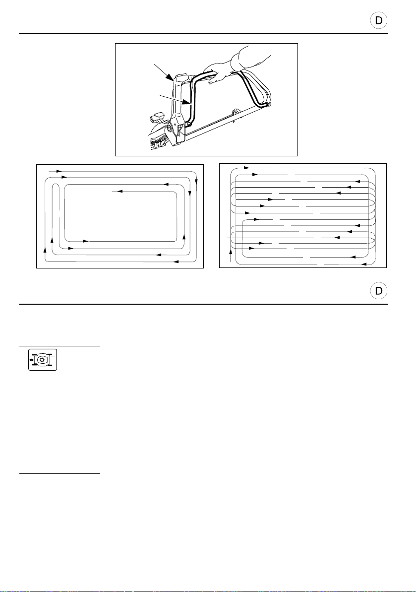
EMPFEHLUNGEN FÜR DEN BETRIEB
VORSICHT:
A
B
[3]
1
2
3
4
5
6
7
8
9
16
15
14
13
12
11
10
[4]
[2]
[1]
5. Warten Sie bis der Motor seine Normalleistung erreicht hat, bevor Sie mit dem Mähen beginnen.
6. Für das Mähen mit automatischem Antrieb, den Fahrantriebshebel [1] gegen das
Lenkgestänge des Rasenmähers drücken und in dieser Stellung beibehalten.
ZUR BEACHTUNG:
• Der Fahrantriebshebel hat die gleiche Wirkung wie ein Ge schwindigkeits- regler in
Abhängigkeit von seiner Position. Er kann die Geschwindigkeit zwischen Null und der durch
den Schalthebel vorgewählten Höchst- geschwindigkeit regeln. Die Höchstg eschwindigkeit
wird erreicht, wenn der Schalthebel auf die Höchstgeschwindigkeit eingestellt ist und der
Fahrantriebshebel gegen das Lenkgestänge festgehalten wird.
• Bitte den Hebel der Messerkupplung immer ganz ein- oder a usrücken. Dies verhi nde rt das
Abwürgen des Motors und schützt den Kupplungs- mechanismus vor übermäßigen
Verschleiß.
7. Fahrantrieb durch Loslassen des Hebels ausschalten [1].
8. Mähantrieb durch Loslassen des Messerkuplungshebels [2] abschalten.
ZUR BEACHTUNG:
• Bei hohem Gras ist es vorteilhaft, in Etappen vorzugehen, indem man die Schnitthöhe und/
oder die Fahrgeschwindigkeit bei jedem Durchgang weiter heruntersetzt. Dadurch wird
vermieden, daß sich der Auswurftunnel verstopft.
• Es ist ebenfalls möglich, kleinere Flächen ohne Fahrantrieb zu mähen.
• Bei hohem Gras ist es sinnvoll die Schnitthöhe in Stufen zu reduzieren. Dies verhindert d as
Verstopfen des Tunnels zum Grasfangsack. Beim Überwechseln auf andere Rasenflä cken,
Überfahren von Bordsteinen, Engstellen etc., Messerantrieb auskuppeln.
[3]
40
Mähweg für kleine Rasenflächen
[4]
Mähweg für große Rasenflächen
Page 41

PRÉCAUTION :
OPERATING HINTS AND TIPS
CAUTION:
5. Wait for the engine to get up to speed before starting cutting.
6. To cut in self propulsion, push the drive clutch lever [1] against the handle and hold it there.
NOTE:
• The drive clutch lever acts as a variable sp eed unit according to its position. It can
vary the speed between zero and the maximum speed preselected with the shift l ever. The
maximum speed is reached when the shift lever is put on the maximum speed and the clutch
lever is held against the handle.
• Move the lever quickly from one end of its travel to the other, so that the clutch is always either
fully engaged or fully disengaged. This avoids stalling the engine and increases the service
life of the clutch mechanism.
7. To stop the mower moving, release the clutch lever [1].
8. To stop the blade rotating, release the blade clutch control lever [2].
NOTE:
• If the grass is long, it is preferable to cut in stages, reducing the cutting height and/or forward
speed at each pass. You will thus avoid choking the discharge outlet.
• It is possible not to use the travel when cutting in restricted spaces.
• Also, the transmission may be used to move the mower without the blade being enga ged
(paths, around flower beds, etc.).
[3] How to mow a small area [4] How to mow a largel area
CONSEILS D’UTILISATION
5. Attendre que le moteur ait repris son régime avant de commencer la tonte.
6. Pour tondre en propulsion automatique, pousser le levier d’embrayage d’avancement [1]
contre le guidon et le maintenir.
NOTE :
• Le levier d’embrayage d’avancement agit comme un variateur de vitesse en
fonction de sa position. Il peut faire varier la vitesse entre zéro et la vitesse maximale
présélectionnée au levier de changement de vitesse.
La vitesse maximale est atteinte lorsque le levier de changement de vitesse est placé sur
la vitesse maximale et le levier d’embrayage e s t mai nte nu contre le guidon.
• Exercer un mouvement rapide et complet sur le levier d’embrayage d’avancement pour qu’il
soit toujours totalement engagé ou arrêté. Ceci permet de prolonger la durée de service du
mécanisme de transmission.
7. Pour arrêter l’avancement de la tondeuse, relâcher le levier d’embrayage d’avancement [1].
8. Pour stopper la rotation de la lame, relâcher le levier d’embrayage de lame [2].
NOTE :
• Si l’herbe est haute, il est préférable de tondre par étapes en réduisant la hauteur de coupe et/
ou la vitesse d’avancement à chaque passage. Vous éviterez ainsi un engorgement du tunnel
d’éjection.
• Il est possible de ne pas utiliser l’avancement lors de la tonte dans des en droits de surface
restreinte.
• De même, l’embrayage d’avancement peut être utilisé pour le déplacement de la tondeuse,
sans engager l’embrayage de lame (allées, massifs, etc...).
[3]
Modèle de tonte d’un petit terrain
[4]
Modèle de tonte d’un grand terrain
41
Page 42
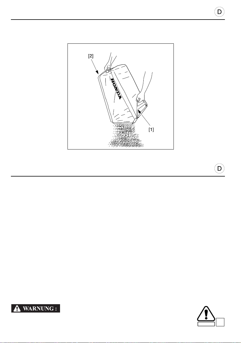
EMPFEHLUNGEN FÜR DEN BETRIEB
VORSICHT:
VORSICHT:
SICHERHEIT
BETRIEB IN GROßEN HÖHEN
In Höhenlagen über 1800 m ist das von einem normalen Rasenmähervergaser erzeugte
Gasgemisch zu fett (= benzinreich). Die Motorleistung ist schwächer und der Verbrauch sehr hoch. In
diesem Sonderfall lassen Sie bitte von Ihrem Honda-Fachgeschäft eine Vergaserdüse mit kleinerem
Durchmesser einbauen und die Regelschraube des Benzin-/Luft-Gemisches vom Fachmann am
Betriebsort neu einstellen. Ohne diese Vergaseränderungen wirken sich Höhen über 1800 m sehr
ungünstig auf die Leistung Ihres Gerätes aus. Wenn die Änderung durchgeführt wurde, n immt die
Leistung in Höhen über 1800 m nur noch um 3.5% pro 300 m ab.
• Wenn Sie einen Rasenmäher besitzen, dessen Vergaser für Höhenlagen umgerüstet wurde
und ihn, in normalen Höhen betreiben, wird der Motor infolge des zu mageren Benzin-/LuftGemisches zu heiß und kann Schaden erleiden.
AUSLEEREN DES GRASFANGSACKS
Die Füllung des Sacks macht sich der Reihe nach bemerkbar durch: Nachlassen der Aufblähung durch
den Mähwind, Geräuschänderung des Rasenmähers, Liegenbleiben von Schnittgut auf dem Mähweg.
1. Motor stoppen.
2. Deckel anheben und Sack abnehmen (siehe Seite 18).
3. Sackentleerung: Halten Sie den Grasfangsack am Griff [1]. Halten Sie den Grasfangsack an
der hinteren [2] Seite und entleeren Sie das Gras.
4. Bringen Sie den Sack wieder am Mäher an (siehe Seite 18).
• Niemals den vollen Grassack am Rasenmäher oder in geschlossenen Gebäuden belassen.
Bei heißem Wetter beginnt das Gras schnell unter Wärmeentwicklung zu gären. Brandgefahr!
Sich vergewissern, daß das Grasfangsackhalteelement sicher
geschlossen ist, bevor Sie den Rasenmäher verwenden (Auswurfdeckel).
42
C11
Page 43

PRÉCAUTION :
PRÉCAUTION :
OPERATING HINTS AND TIPS
CAUTION:
CAUTION:
USING THE MOWER AT HIGH ALTITUDES
At high altitudes, the standar d gas/air mixture in the carburettor is much too rich: t his will reduce
performance and increase fuel consumption. It is possible to improve the high altitude performance by
fitting the carburettor with a smaller diameter jet and by adjusting the pilot screw. If you use your mower
at an altitude of more than 1800 metres above sea level, we recommend that you have these
modifications made by your approved Honda dealer. Even with the appropriate modifications made to
the carburettor, engine power will be reduced by about 3.5 % for every 300 metres of altitude. However,
the altitude will have a m uch grea ter effect o n power if these m odificatio ns are no t carried ou t.
• Running the mower at an altitude less than that for which the carburetto r is adjusted may
cause overheating and seriously damage the engine, due to the gas/air mixture being far too
weak.
EMPTYING THE GRASS BAG
When the grass bag becomes too full, grass collection is no longer efficient (the sound of the
mower changes and the bag is no longer puffed up by the air from the blade).
1. Stop the engine.
2. Remove the grass bag (see page 19).
3. Empty the ba g: Hold the bag b y the handle [1]. Grasp the ba g rear side [2 ] and sha ke it to
remove the grass.
4. Reinstall the grass bag on the mower (see page 19).
• To reduce the fire risk, never leave grass cuttings or leaves in the grass bag, or in or near
buildings. Decomposing vegetable matter causes a high temperature rise.
Make sure that the grass bag fastener is securely closed before use
(discharge guard).
CONSEILS D’UTILISATION
FONCTIONNEMENT EN HAUTE ALTITUDE
En haute altitude, le mélange standard essence/air du carburateur sera beaucoup trop riche : les performances
diminueront et la consommation d’e ssence augmentera . On peut améliorer les performances en ha ute altitude,
en installant dans le carburateur un gicleur d’un plus petit diamètre et en réglant la vis de richesse. Si vous faites
fonctionner votre tondeuse à une altitude supérieure à 1800 mètres au-dessus du niveau de la mer, il est
recommandé de faire exécuter ces modifications sur le carburateur par votre concessionnaire Honda agréé.
Même avec les modifications appropriées apportées au carburateur, la puissance du moteur diminuera
d’environ 3.5 % pour chaque tranche d’augmentation d’altitude de 300 mètres. Cependant, l’incidence de
l’altitude sur la puissance se fera beaucoup plus sentir, si ces modifications n’ont pas été appo rtées.
• Faire fonctionner la tondeuse à une altitude inférie ure à celle pou r laquel le le carbur ateur a
été réglé peut provoquer une surchauffe et causer de sérieux dommages au moteur, dus à un
mélange beaucoup trop pauvre air/essence.
VIDAGE DU SAC DE RAMASSAGE
Lorsque le sac à herbe devient trop plein, le ramassage n’ est plus efficace (le bruit de la
tondeuse change et le sac n’est plus gonflé par le souffle de la lame).
1. Arrêter le moteur.
2. Retirer le sac (voir page19).
3. Vider le sac : Maintenir le sac par l’intermédiaire de la poignée [1]. Saisir le sac par l’arrière [2]
et le secouer pour évacuer l’herbe.
4. Remettre le sac en place sur la tondeuse (voir page 19).
• Afin de réduire tout risque d’incendie, ne jamais laisser d’herbe coupée ou des feuilles dans
le sac de ramassage, à proximité ou dans un bâtime nt. La décomposition des substances
végétales provoque une importante élévation de température.
S’assurer, avant utilisation, que le dispositif de fermeture du sac est bien
bloqué (protecteur de décharge).
SAFETY
SECURITE
C11
C11
43
Page 44
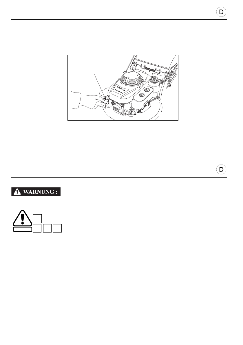
WARTUNGSHINWEISE
VORSICHT:
SICHERHEIT
D7C1C18
D8
[1]
Regelmäßige Pflege ist die beste Garantie für lange Lebensdauer und störungsfreienBetrieb!
Vor Beginn der Wartung unbeabsichtigte s Anspringen des Motors verhindern durch
Abziehen des Kerzensteckers [1].
• Verwenden Sie für Wartung und Reparatur nur Original Honda-Ersatztei le. Ersatzteile, die
nicht von gleicher Qualität sind, können zu Schäden am Rasenmäher führen.
• Auspuff und Motor erreichen im Betrieb sehr hohe Temperaturen, die bei Berührung
Verbrennungen verursachen und Materialien entflammen können, die mit heißen
Rasenmäherteilen in Berührung kommen. Daher vor jeder Wartung den Rasenmäher
mindestens 15 Minuten abkühlen lassen.
• Um eine lange Lebensdauer und eine gute Schnittleistung zu gewährleisten, muß die
Unterseite des Gehäuses sauber und frei von Grasresten gehalten werden. Hierzu wird sie
nach dem Mähen mit einer Bürste gereinigt. Entfernen Sie Rost und tragen Sie einen
Rostschutzanstrich auf. Reinigung und Schutz gegen Rost sind besonders wichtig vor der
Einlagerung Ende der Saison.
• Damit er seine volle Leistung behält, ist der Rasenmäher regelmäß ig zu überprüfen und
einzustellen. Regelmäßige Wartung ermöglicht eine lange Lebensdauer. Die notwendigen
Wartungsintervalle und die Art der durchzuführenden Arbeiten sind auf Seite 71 beschrieben.
44
Page 45

PRÉCAUTION :
D7C1C18
D8
MAINTENANCE
CAUTION:
SAFETY
D7
C1C18
D8
Regular maintenance will ensure a long life for your mower.
To prevent accidental start-up, shut off the engine and disconnect the spark plug cap [1] .
• Use only genuine Honda parts or their equivalent for maintenance or repair. Replacement
parts which are not of equivalent quality may damage the mower.
• The engine and the muffler reach temperatures high enough to cause burns and start fires if
flammable materials are to be found nearby. Allow the e ngine to cool down for 15 minutes
before carrying out maintenance operations.
• For longer service life and greater efficiency, keep the underside of the mower clean and free
from grass clippings by cleaning it with a wire brush as scraper. Remove of rust and applying
a corrosion inhibitor are especially important before seasonal storage.
• Periodic inspection and adjustment of the mower is essential if a high level of performance is
to be maintained. Regular maintenance will ensure a long service li fe. The required service
intervals and the kind of maintenance to be performed are described on page 72.
ENTRETIEN
Un entretien régulier est le garant d’une longue durée de vie de la tondeuse.
Pour éviter tout démarrage accidentel, débrancher le capuchon de la bougie
d’allumage [1].
SECURITE
• Pour l’entretien ou les réparations, n’employer que des pièces Honda d’origine . Des pièces
de rechange qui ne seraient pas de même qualité pourraient endommager la tondeuse.
• Le moteur et le pot d’échappement atteignent des températures suffisantes pour provoquer
des brûlures et déclencher un incendie si des matières inflammables se trouvent à proximité.
Laisser le moteur refroidir pendant 15 minutes avant tout entretien.
• Pour assurer une plus longue durée de vie ainsi qu’un meilleur rendement, il est
indispensable de tenir le dessous de la tondeuse propre et sans débris d’herbe en le
nettoyant à l’aide d’une brosse métallique et d’un grattoir. Il est également recommandé de
retirer toute trace de rouille et d’appliquer une peinture anticorrosion. Ces opérations sont
indispensables avant le remisage saisonnier.
• Des vérifications ainsi que des réglages périodiques de la tondeuse sont essen tiels pour
maintenir un niveau élevé de performances. Un entretien régulier est le garant d’une longue
durée de vie. Les intervalles d’entretien requis, ainsi que la nature de cet entretien figurent sur
le tableau de la page 73.
45
Page 46
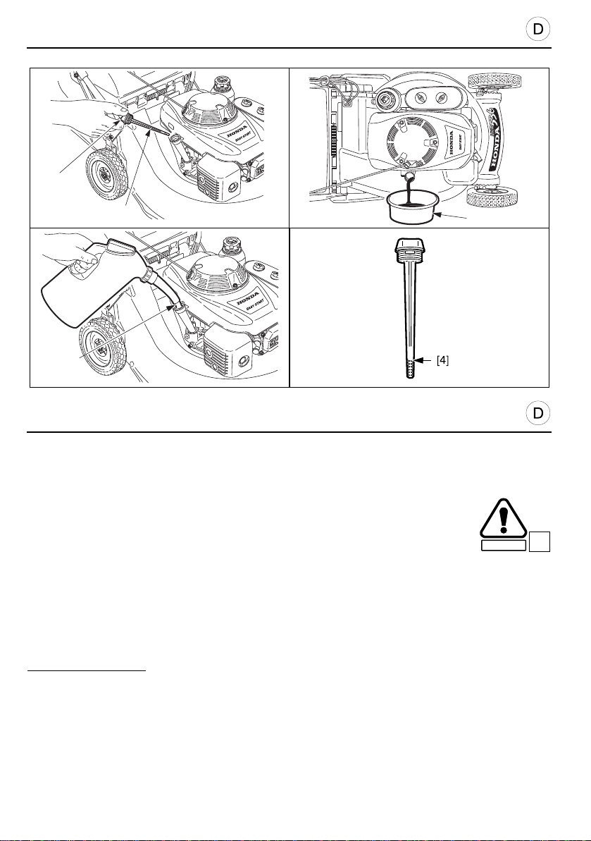
WARTUNGSHINWEISE
VORSICHT:
SICHERHEIT
B3
[3]
[4]
[1]
[2]
MOTORÖLWECHSEL
Altes Öl ablassen, solange der Motor noch warm ist: das geht schneller und gründlicher!
• Waschen Sie sich nach dem Ölwechsel die Hände mit etwas
Scheuermittel, Seife und Wasser.
1. Den Deckel des Öleinfüllstutzens [1] abnehmen.
2. Rasenmäher nach rechts kippen.
3. Flache Wanne [2] unter den Öleinfüllstutzen schieben.
4. Altes Öl l ang genug ausfließen lassen, danach Rasenmäher wieder auf alle vier Räder
stellen.
5. Frisches Öl bis zur oberen Marke [4] des Meßstabs einfüllen [3].
6. Öleinfüllstutzen [1] zuschrauben.
ZUR BEACHTUNG:
sondern in gekennzeichnetem (wasserunlöslicher breiter Filzschreiber), altem Ölkanister
sammeln und gelegentlich in einer Autowerkstatt zum Recycling abliefern.
46
Gebrauchtes Motoröl niemals einfach wegschütten (Umweltschutz!),
Page 47
PRÉCAUTION :
SECURITE
B3
MAINTENANCE
CAUTION:
SAFETY
B3
CHANGING THE ENGINE OIL
Drain the oil while the engine is still hot, so that the oil drains quickly and completely.
• Used engine oil can cause skin cancer if it remains in contact with the skin for
long periods. Although this is highly unlikely unless you handle used oil every
day, we recommend that you wash your hands thoroughly with soap and water
each time you handle used engine oil.
1. Remove the filler cap [1].
2. Tip the mower on its side.
3. Place a receptacle [2] under the casing filler tube hole.
4. Return the mower to the upright position on its wheels when the casing is completely empty.
5. Fill up [3] to “high level” [4] using the recommended oil.
6. Screw the filler cap [1] fully on to avoid the risk of leaks.
The used engine oil must be disposed of in a manner which respects the environment.
NOTE:
We recommend that you take it to a service station who will ensure that it is recycled. Never
dispose of used engine oil in dustbins or pour it away on the ground, in the gutter or down the
drains.
ENTRETIEN
CHANGEMENT DE L’HUILE MOTEUR
Vidanger l’huile pendant que le moteur est encore chaud, pour assurer une vidange rapide et
complète.
• Un contact fréquent et prolongé avec l’huile moteur usagée peut provoquer un
cancer de la peau. Bien que cette éventualité soit peu probable, il est
cependant recommandé de bien se laver les mains à l’eau et au savon
aussitôt après avoir manipulé de l’huile moteur usagée.
1. Retirer le bouchon [1] de remplissage de l’huile.
2. Basculer la tondeuse sur le côté.
3. Placer un récipient [2] sous l’orifice du tube de remplissage du carter.
4. Replacer la tondeuse sur ses roues lorsqu’il ne reste plus d’huile dans le carter.
5. Effectuer le plein d’huile [3] jusqu’au repère “niveau supérieur” [4] en utilisant de l’huile
recommandée.
6. Revisser le bouchon [1] à fond pour éviter tout risque de fuite.
Il vous faut vous débarrasser de l’huile moteur usagée en respectant l’environnement.
NOTE :
Nous vous conseillons de l’apporter dans un récipient éta nche à une station-service qui se
chargera de son recyclage. Il ne faut surtout pas la jeter dans une poubelle ou encore la verser
sur le sol, dans des canalisations ou dans des égouts.
47
Page 48
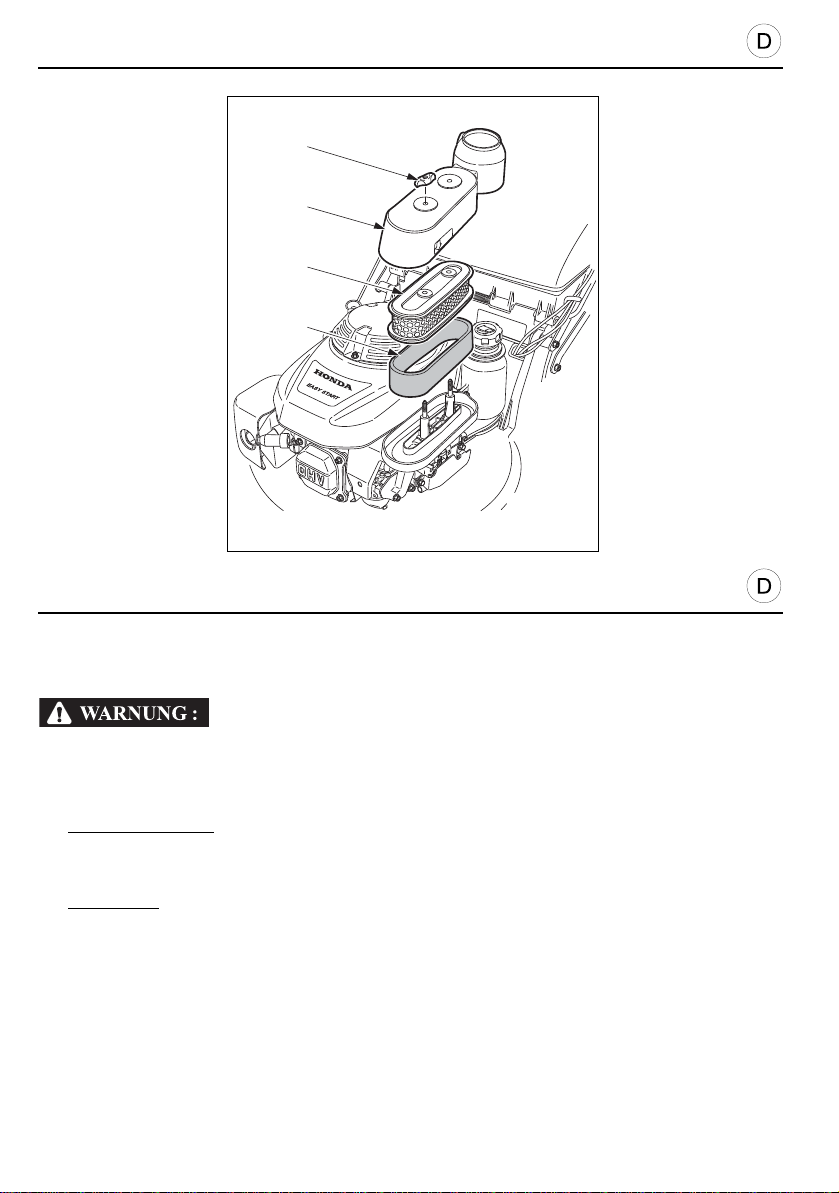
WARTUNGSHINWEISE
[1]
[2]
[4]
[3]
LUFTFILTER
Verschmutzte Luftfilter verringern die Motorleistung durch zu geringe Luftzufuhr zum Vergaser.
Regelmäßige Kontrolle, besonders in staubiger Atmosphäre ist daher unerläßlich.
Honda-Trockenfiltersätze nicht in Benzin reinigen!
1. Entfernen Sie die Flügelmuttern [1] und die Abdeckung [2].
2. Fil terelemente [3] und [4] herausn ehmen, trennen und prüfen. Beschädigte Fi lter müssen
durch neue ersetzt werden (Honda-Kundendienst).
3. Schaumstoff-Filter
mit klarem Wasser nachspülen und ausdrücken. Danach mindestens 12 Stunden trocknen
lassen. Bei Zeitmangel mit trocknen.
Schaumstoffilter nur trocken wieder einbauen, nicht mit Öl tränken.
4. Papierfilter
danach mit Preßluft oder Staubsauger reinigen, dies jedoch immer entgegen der
Ansaugrichtung. Nicht bürsten!
48
[3]: Filter mit reichlich Spülmittelzugabe in heißem Wasser auswaschen,
[4]: Niemals naß behandeln! Zuerst auf harter Unterlage vorsichtig ausklopfen,
Page 49

MAINTENANCE
AIR CLEANER
A dirty air cleaner will reduce the flow of air to the carburettor. To prevent the carburetto r
operating inefficiently, the air cleaner must be regularly maintained.
Never clean the air cleaner elements using gas or flammable solvents ; this could cause
a fire or an explosion.
1. Remove wing nuts [1] and cover [2].
2. Remove the elements [3] and [4] and separate them. Carefully check them for holes or
tears; replace if necessary.
3. Foam element
flash-point solvent and allow to dry.
Dip the element in clean engine oil and squeeze out all excess oil. Th e engine will smoke
during start-up if too much oil is left in the foam.
4. Paper element
blow compressed air through it from the inside out. Never try to remove the dirt by brushing
the filter since this will only force the impurities into the fibres.
[3]: clean in hot soapy water, rinse and allow to dry thoroughly or clean in high
[4]: tap the element lightly against a hard surface to remove excess dirt, or
ENTRETIEN
FILTRE À AIR
Un filtre à air encrassé diminuera le débit de l’air au carburateur. Pour préven ir tout mauvais
fonctionnement du carburateur, il est primordial d’entretenir régulièrement le filtre à air.
Ne jamais se servir d’essence ou de solvants infla mmables p our nettoye r les éléme nts
du filtre à air ; cela pourrait en effet provoquer un incendie ou une explosion.
1. Retirer les écrous papillon [1] et le couvercle [2].
2. Déposer les éléments filtrants [3] et [4] et les séparer. Vérifier attentivement qu’ils ne soient
ni percés, ni déchirés ; les remplacer si nécessaire.
3. Élément en mousse
complètement sécher. Il peut également être nettoyé avec un solvant ininflammable et être
séché.
Plonger l’élément de mousse [3] dans de l’huile moteur propre et le presser pour en extraire
l’excédent. Le moteur fumera au démarrage, s’il est resté trop d’hu ile dans l’élément de
mousse.
4. Élément en papier
faire sortir la saleté, ou envoyer de l’air comprimé à travers le filtre, de l’intérieur vers
l’extérieur. Ne jamais essayer d’enlever la saleté en brossant le filtre, car au contraire, cela
ferait pénétrer des impuretés à l’intérieur des fibres.
[3] : le nettoyer dans de l’eau chaude savonneuse, le rincer et le laisser
[4] : taper légèrement l’élément filtrant contre une surface dure, afin d’en
49
Page 50
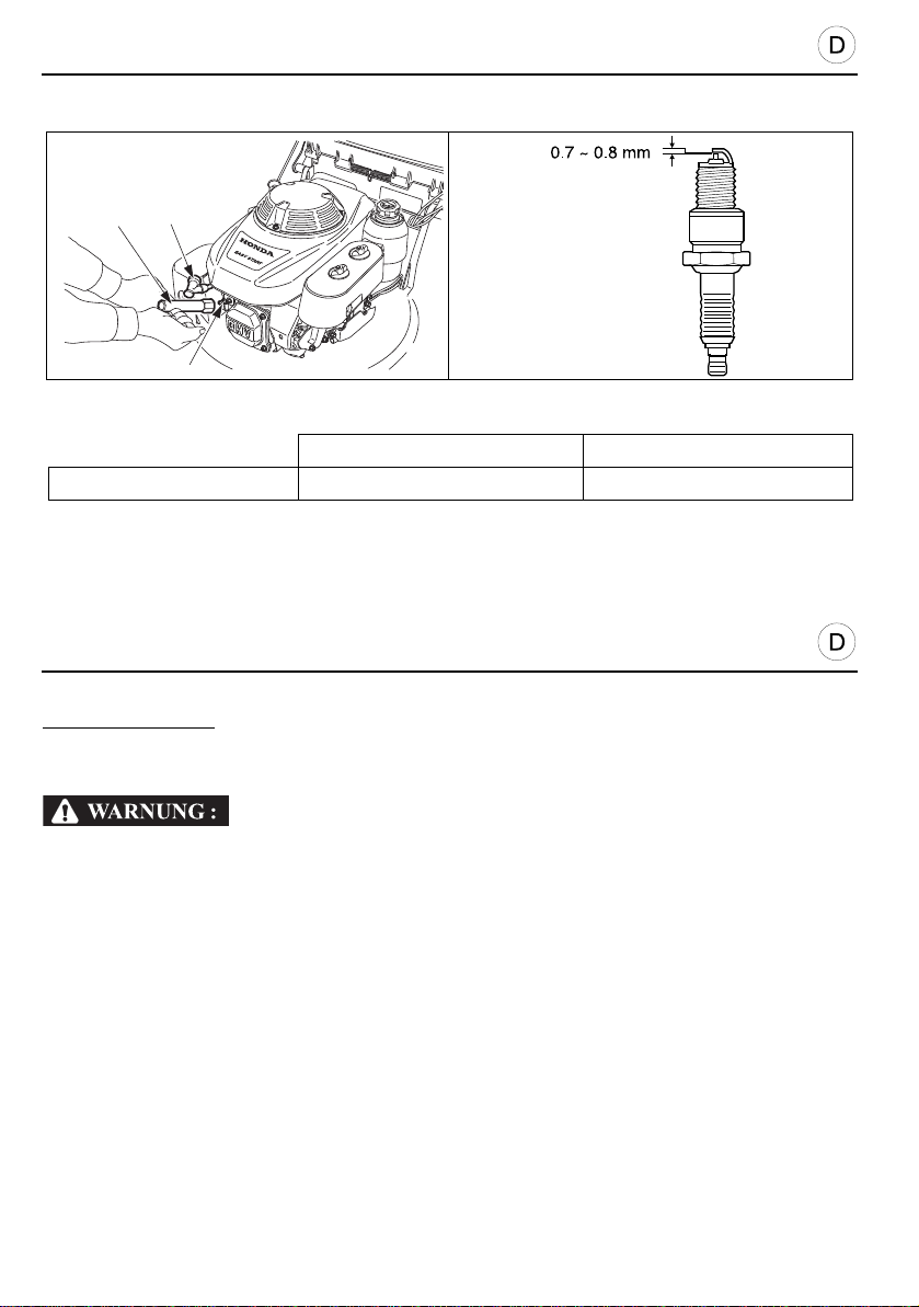
WARTUNGSHINWEISE
VORSICHT:
VORSICHT:
[1]
[3]
[2]
[4] NGK NIPPONDENSO Co., Ltd
HRD536 - HRH536 BPR5ES W16 EPR-U
ZÜNDKERZENWECHSEL
Standardkerzen: [4]
• Nur die vorgeschriebene Kerzentype verwenden! Ungeeignete Kerzen können den Motor
beschädigen.
Wenn der Motor vor dem Kerzenwechsel bereits gelaufen ist, erst abkühlen lassen:
Verbrennungsgefahr an Kerze und Auspuff!
1. Kerzenstecker [1] abziehen und Zündkerze [2] mit dem Kerzenschlüssel [3] durch
Linksdrehen (gegen den Uhrzeigersinn) ausschrauben.
2. Kerze sorgfältig prüfen. Braun-schwarze Ablagerungen am Kerzenunterteil mit Metallbürste
oder Schmirgelpapier entfernen. Hellen Keramik-Isolator prüfen: falls er Sprünge aufweist,
darf die Kerze nicht wieder eingebaut werden!
3. Gemäß Abbildung den Elektrodenabstand messen. Er soll zwischen 0,7 und 0,8 mm liegen.
Falls er größer ist - und die Kerze sich ansonsten in gutem Zustand befindet - die Zündkerze
mit nach unten gerichteten Elektroden leicht auf eine harte Unterlage klopfen. Vorher
möglichst ein Stückchen 0.8 mm starkes Blech zwischen die Elektroden schieben, damit
sich die Außenelektrode beim Verbiegen nicht zu weit der Innenelektrode nähert.
4. Nachsehen ob der Metalldichtring in Ordnung ist, Kerze von Hand wieder einschrauben. Vorsicht,
der Zylinderkopf besteht aus Aluminium: beim Einschrauben keine Gewalt anwenden.
5. Gebrauchte Kerze 1/8 bis 1/4 Umdrehung mit Kerzenschlüssel festziehen. Bei neuen
Kerzen ist 1/2 bis 1 Umdrehung zum Zusammenpressen der Dichtung nötig.
6. Zündkabel mit Kerzenstecker wieder aufstecken.
• Kerzen müssen richtig angezogen werden. Lassen Sie sich eventuell vom Fachmann helfen.
50
Lose Kerzen werden zu heiß, zu festes Anziehen kann eventuell den Zylinderkopfbeschädigen.
Page 51

PRÉCAUTION :
PRÉCAUTION :
MAINTENANCE
CAUTION:
CAUTION:
SPARK PLUG
Standard plugs: [4]
• Use only recommended spark plugs. Using spark plugs with inappropriate temperature
ranges may damage the engine.
If the engine has just been run, do not touch the muffler and the spark plug which will still
be very hot.
1. Pull off spark plug cap [1] and remove spark plug [2] using a plug spanner [3].
2. Carefully inspect the spark plug. Replace the plug if there are a lot of deposits or if the
insulator is cracked or broken.
3. Measure the plug gap using a set of feeler gauges ; the gap must b e be tween 0.7 a nd 0.8
mm. If adjustment is necessary, carefully bend the side electrode.
4. Check that the sealing washer is in good condition ; then screw the plug down by hand until
finger tight and correctly seated.
5. Using a plug spanner, give an additional 1/2 turn for a new spark plu g, to compress the
washer. If you refit the same plug, just 1/8 to 1/4 turn will do from the finger tight position.
6. Refit the spark plug cap.
• The spark plug must be correctly tightened. A plug incorrectly screwed down can become
very hot and damage the engine.
ENTRETIEN
BOUGIE D’ALLUMAGE
Bougies standards : [4]
• N’utiliser que les bougies recommandées. L’emplo i de bougies ayant un indice thermique
inapproprié peut causer des dommages au moteur.
Si le moteur vient de tourner, ne pas toucher le pot d’échappement et la bougie qui
seraient encore très chauds.
1. Débrancher le capuchon [1] et retirer la bougie [2] à l’aide d’une clé à bougie [3].
2. Examiner attentivement la bougie, la remplacer si les dépôts sont importants ou bien si
l’isolant est fissuré ou cassé.
3. Mesurer l’écartement des électrodes avec un jeu de cales d’épaisseur ; il doit être compris
entre 0,7 et 0,8 mm. Si un réglage est nécessaire, il suffit de tordre soigneusement
l’électrode latérale.
4. Vérifier si la rondelle d’étanchéité est en bon état ; puis revisser la bougie à la main jusqu’à
l’assise sur son siège.
5. A l’aide d’une clé, donner 1/2 tour supplémentaire à une bougie neuve, afin de comprimer la
rondelle. Si vous remontez la même bougie, il suffira de donner 1/8 à 1/4 de tour après la
mise en place de la bougie sur son siège.
6. Replacer le capuchon de la bougie.
• La bougie d’allumage doit être correctement serrée. Une bougie mal vissée peut devenir très
chaude et endommager le moteur.
51
Page 52
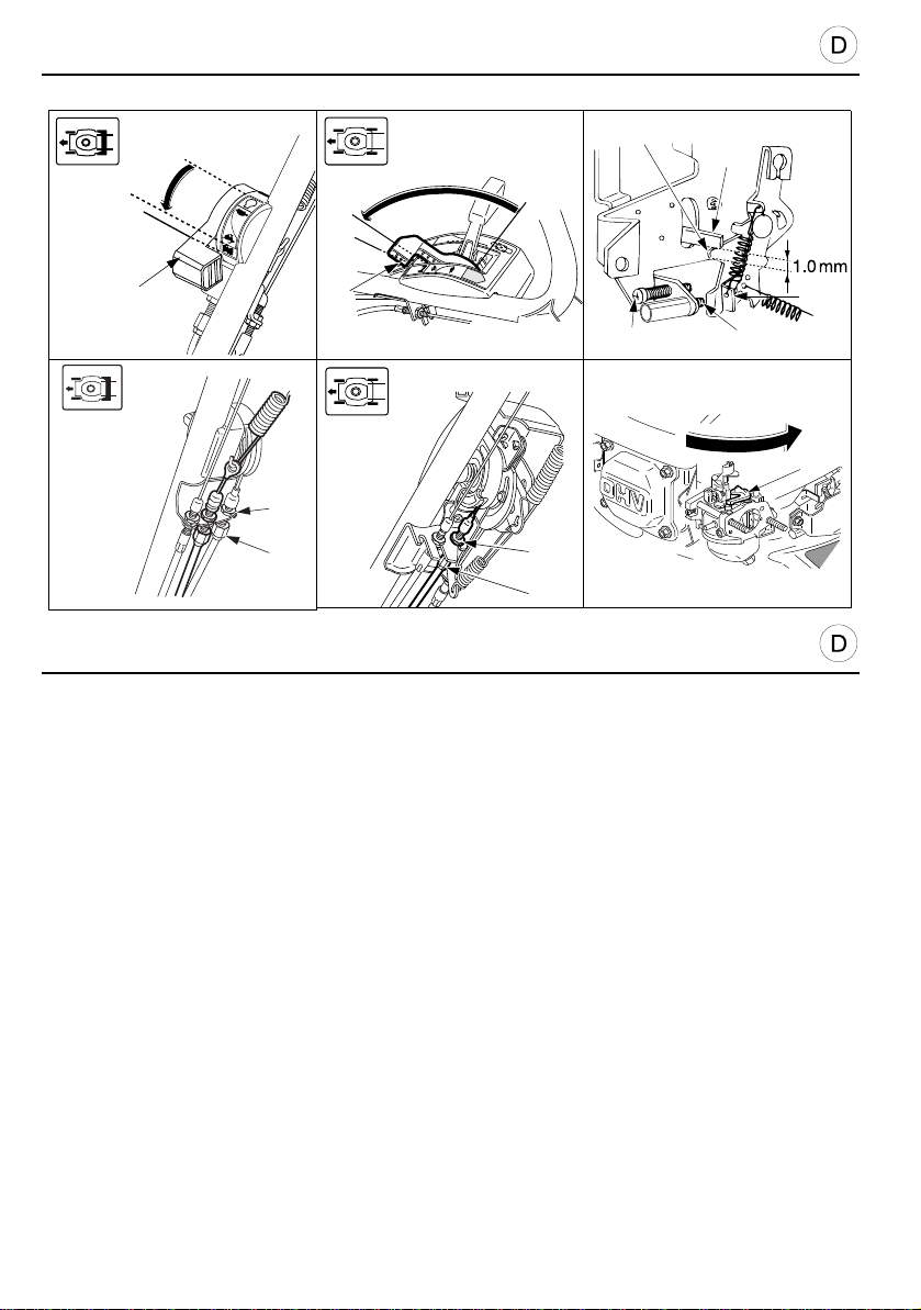
WARTUNGSHINWEISE
VORSICHT:
[D]
[B]
[A]
[1]
[2]
[3]
[4]
[8]
[9]
[7]
[5]
[6]
[B]
[A]
[1]
[D]
P
STO
[2]
[3]
NACHSTELLEN DES GASZUGS
1. Den Gashebel [1] auf die Position “SCHNELL” [B] stellen. Der Hebel [9] soll in dieser
Stellung gerade noch den Startarm [7] berühren (Spiel 0-1 mm).
2. Falls eine Justierung erforderlich ist, Konter- mutter [2] am Gaszug lösen und
Justierstück [3] so einstellen, daß das Spiel 0-1mm beträgt. Anschließend die Mutter wieder
kontern. Einstellung nochmals über- prüfen. Zur Neueinstellung, Konter mutter am
Gasseilzug lockern und Seilzug nach justieren. Bringen Sie den Gashebel in die “START”Position [A] und prüfen Sie, ob der Choke-Arm [7] vollständig angehoben wird.
3. Drücken Sie den Chokehebel [4] mit dem Finger nach rechts um zu prüfen, ob der Hebel
den Endanschlag erreicht. Schraube [8] so einstellen, daß sie den Arm [9] gerade berührt,
wenn der startarm [7] ganz nach oben gezogen ist.
4. Gashebel in Stellung “SCHNELL” [B] einstellen. Überprüfen, daß der Arm [5] gege n die
Schraube [6] anschlägt. Überprüfen, daß das Spiel zwischen dem Arm [9] und dem
Starterhebel [7] eingehalten wird. Starten Sie den Motor und vergewissern Sie sich, daß der
Motor stehen bleibt wenn der Gashebel auf die “STOPP”-Position [D] gestellt wird Falls
erforderlich, Seilzug nachstellen.
• Falls dies nicht der Fall ist, Gaszug neu justieren. Fragen Sie Ihren Honda-Händler falls Sie
nicht über die erforderliche Erfahrung oder Ausrüstung verfügen.
• Falls kein einwandfreier Betrieb erreicht werden kann, ist die Einstellung von einem
zugelassenen Honda-Konzessionär vornehmen zu lassen, der über die für die sen Eingriff
notwendigen Spezialwerkzeuge verfügt.
52
Page 53

PRÉCAUTION :
MAINTENANCE
CAUTION:
THROTTLE CONTROL CABLE ADJUSTMENT
1. Move the throttle control lever [1] to the “FAST” [B] position. The arm [9] should touch the
choke control [7] (clearance 0 to 1 mm).
2. If an adjustment is necessary, loosen the block nut [2] of the throttle cable and turn the
adjuster [3] as required to obtain the clearance (0 to 1mm). Tighten the lock nut [2] securely.
Place the throttle control lever in the “STARTER” position [A] and check whether the choke
arm [7] is completely raised.
3. Push the choke lever [4] with your finger to check whether it is all the way to the right. Adjust
the screw [8] so that is just touches the throttle arm [9], with the choke arm [7] completely
raised.
4. Place the throttle control lever on the “FAST” position [B]. Make sure that the arm [5] is right
against the screw [6]. Check that the clearance between the arm [9] and the choke arm [7]
is correct. Start the engine and make sure it stops when the throttle control lever is moved to
the “STOP” position [D]. Readjust the cable if necessary.
• If you do not have the required skills or equipment, it is recomme nded to ask your Honda
dealer for adjustment.
• If the mower cannot be operated correctly, have it adjusted by an ap proved Honda dealer,
who has the special tooling necessary for this work.
ENTRETIEN
RÉGLAGE DU CÂBLE DE COMMANDE DES GAZ
1. Amener la manette de commande des gaz [1] sur la position “RAPIDE” [B]. Le bras [9] doit
juste toucher la commande de starter [7] (0 à 1 mm de jeu).
2. S’il est nécessaire d’effectuer un réglage, desserrer le contre-écrou [2] du câble de
commande et manœuvrer l’écrou tendeur [3] afin, selon le cas, d’augmenter ou de diminuer
le jeu (0 à 1 mm). Resserrer le contre-écrou [2]. Amener la manette des gaz en position
“STARTER” [A] et vérifier que le bras de starter [7] soit levé à fond.
3. Pousser la biellette du volet de starter [4] avec le doigt afin de vérifier si elle va bien
complètement à droite. Régler la vis [8] afin qu’elle touche juste le levier des gaz [9] quand
le bras de starter [7] est levé à fond.
4. Amener le levier des gaz en position “RAPIDE” [B]. Vérifier que le bras [5] soit en butée
contre la vis [6]. Vérifier que le jeu soit respecté entre le bras [9] et la commande de
starter [7]. Mettre le moteur en marche et s’assurer qu’il s’arrête dès que l’on met le levier de
commande des gaz sur la position “ARRÊT” [D]. Régler de nouveau le câble si nécessaire.
• Si vous n’avez pas les compétences ou l’équipement nécessaires à cette opération, il est
recommandé de confier ce réglage à un concessionnaire Honda.
• Si le fonctionnement correct ne peut être obtenu, faire effectuer le réglage par un concessionnaire
Honda agréé, qui dispose de l’outillage spécial nécessaire à cette intervention.
53
Page 54
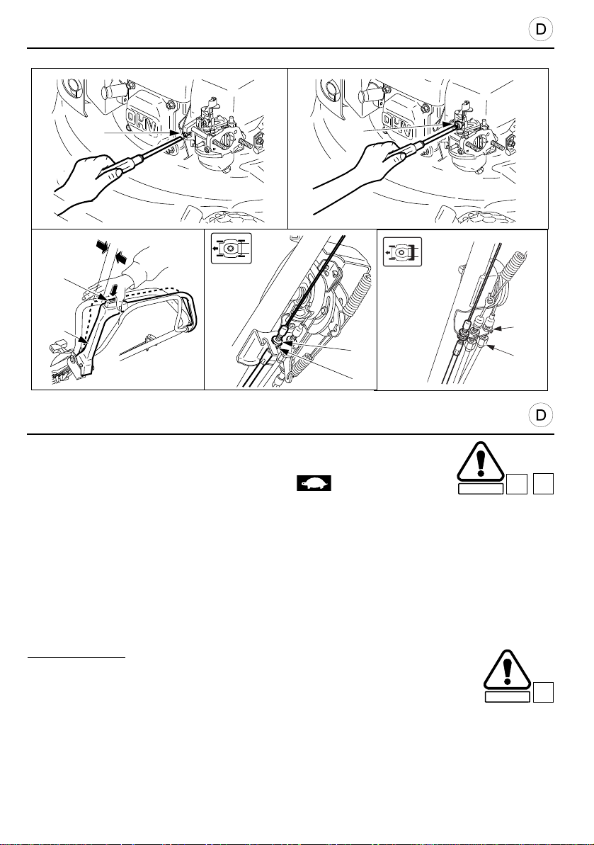
WARTUNGSHINWEISE
[1]
[2]
[3]
[4]
[5]
[6]
[6]
[2]
[3]
VERGASEREINSTELLUNG
1. Motor warmlaufen lassen.
2. Gashebel in Stellung “LANGSAM” schieben .
SICHERHEIT
3. Benzin-Luftgemisch-Stellschraube [1] mit Schraubenzieher so verdrehen, daß der Motor in
Stellung “LANGSAM” die höchste Drehzahl erreicht. Dies ist meistens der Fall, wenn die
Schraube nach Eindrehen bis zum Anschlag (ZU, bei stehendem Motor), zwei
Umdrehungen herausgedreht wird.
4. Nach richtiger Einstellung der Gemisch-Regulierschraube, mit der Drosselklappenein-
stellschraube [2] die normale Leerlauf-Drehzahl einstellen: 1700 ± 150 U/mn
C1
EINSTELLUNG DES ROTOSTOPHEBELS
Verriegelungsknopf [3] gedrückt halten und Kupplungsbügel [5] in Auskuppelstellung (s.Abb.)
hin- und herbewegen. Der Kupplungsbügel soll sich in einem Bereich von ca. 5 bis 10 mm.
Falls erforderlich:
1. Die Sicherungsmuttern [6] mit einem 10 mm Schlüssel lösen.
2. Die Muttern [6] je nach Bedarf nach oben oder nach unten verschieben.
3. Muttern [6] festziehen und Spiel prüfen.
4. Den Motor starten und den Messerkupplungshebel betätigen. Die Prüfung erfolgt am
54
SICHERHEIT
Besten nach Gehör. Wenn das Messer trotz richtig eingestelltem Kupplungsspiel nicht
anläuft oder stoppt, muß eventuell ein dem normalen Verschleiß unterworfenes T eil der
Kupplungsmechanik ersetzt werden. Bringen Sie in diesem Fall Ihren Rasenmäher zu einer
autorisierten Honda Service-Werkstatt.
C12
C16
Page 55
MAINTENANCE
SAFETY
CARBURETTOR ADJUSTMENT
1. Start the engine in the open air and allow it to reach its normal operating
temperature.
2. Place the throttle control lever in “SLOW” position .
3. Screw the pilot screw [1] in or out until you reach the highest idle speed . Generally, the
correct setting is found 2 turns out from the fully in position.
4. When the pilot screw is correctly adjusted, turn the throttle stop screw [2] to obta in the
specified idle speed: 1700 ± 150 rpm
C1
C12
ROTOSTOP SAFETY LEVER CLEARANCE
Measure the clearance [3] at the top of the lever [5] by holding the yellow button [4] pressed in.
It must be between 5 and 10 mm.
If necessary:
1. Undo the lock nuts [6] with a 10 mm spanner.
2. Move the nuts [6] up or down as necessary.
SAFETY
3. Retighten the lock nuts [6] and recheck the clearance.
4. Start the engine outdoors and engage the blade clutch lever. Check that the blade starts to
rotate when you pull the lever to the rear, and that it stops rapidly when the lever is released.
If the blade does not start to rotate or stop as it should, e ven when the cable is corre ctly
adjusted, the system may need to be repaired. Take the mower to an approved Honda
dealer.
C16
ENTRETIEN
RÉGLAGE DU CARBURATEUR
1. Mettre le moteur en route à l’extérieur et attendre qu’il atteigne sa
température normale de fonctionnement.
2. Placer la manette de commande des gaz en position “LENT” .
SECURITE
3. Tourner la vis pilote [1] vers l’intérieur ou vers l’extérieur jusqu’au réglage qui produit la
rotation au ralenti la plus élevée. Le plus souvent, le réglage correct est d’environ 2 tours
vers l’extérieur à partir de la position fermée complète.
4. Après avoir réglé correctement la vis pilote, tourner la vis d’arrêt des gaz [2] pour obtenir la
vitesse de ralenti normale : 1700 ± 150 tr/min.
JEU AU LEVIER DE SÉCURITÉ ROTOSTOP
Mesurer le jeu [3] au sommet du levier [5] en maintenant le bouton jaune [4] enfoncé. Le jeu doit
être compris entre 5 et 10 mm.
Le cas échéant :
1. Desserrer les écrous de blocage [6] avec une clé de 10 mm.
2. Déplacer les écrous [6] vers le haut ou vers le bas suivant nécessité.
3. Resserrer les écrous [6] et revérifier le jeu.
4. Démarrer le moteur à l’extérieur et engager le levier d’embrayage de lame . Vérifier qu e la
lame se mette en route lorsque vous poussez le levier et s’arrête rapidement lorsque vous
le relâchez. Si la lame ne se met pas en route ou ne s’arrête pas comme elle le devrait alors
que le réglage du câble est correct, il est possible qu’une réparation soit nécessaire.
Consulter un concessionnaire agréé Honda.
SECURITE
C1
C12
C16
55
Page 56
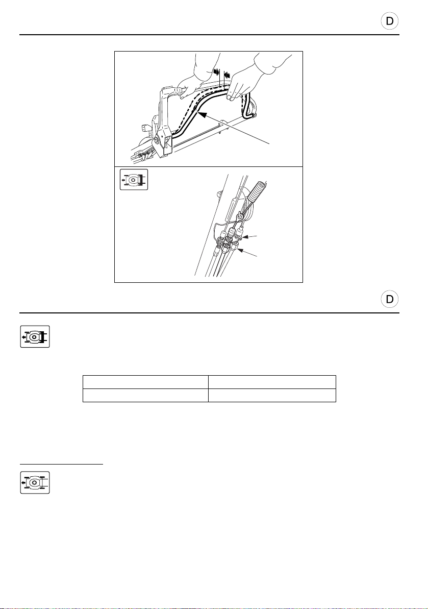
WARTUNGSHINWEISE
[2]
[1]
[2]
[3]
EINSTELLUNG DES FAHRANTRIEBSHEBELS
Spiel [1] an der Oberkante des Hebels [2] messen, wenn dieser völlig entlastet ist.
Das Spiel muß in einem Bereich von:
HRD536 HRH536
5 - 15 mm 5 - 10 mm
1. Die Sicherungsmuttern [3] mit einem 10 mm Schlüssel lösen und die Einstellmutter [4] je
nach Bedarf nach oben oder unten schieben.
2. Die Sicherungsmuttern wieder anziehen und das Spiel erneut überprüfen.
ZUR BEACHTUNG:
Übergehen Sie direkt zum Abschnitt “Einstellung des Bodenzuges für die
Geschwindigkeitsverstellung”, Seite 58.
56
Page 57
MAINTENANCE
DRIVE CLUTCH LEVER CLEARANCE
Measure the clearance [1] at the tip of the lever [2] when completely released.
The clearance must be between:
HRD536 HRH536
5 - 15 mm 5 - 10 mm
1. Undo the lock nuts [3] with a 10 mm spanner and move the adjusting nut [4] up or down as
necessary.
2. Tighten the nuts and check the clearance again.
NOTE:
Refer directly to the section “Adjusting the shift lever”, page59.
ENTRETIEN
JEU AU LEVIER D’EMBRAYAGE D’AVANCEMENT
Mesurer le jeu [1] au sommet du levier [2] en position totalement relâchée.
Le jeu doit être compris entre :
HRD536 HRH536
5 - 15 mm 5 - 10 mm
1. Desserrer les écrous de blocage [3] avec une clé de 10 mm et déplacer l’écrou-régleur [4]
vers le haut ou le bas suivant nécessité.
2. Resserrer les écrous de blocage et revérifier le jeu.
NOTE :
Se reporter directement à la section “Réglage du levier de changement de vitesse”,
page 59.
57
Page 58
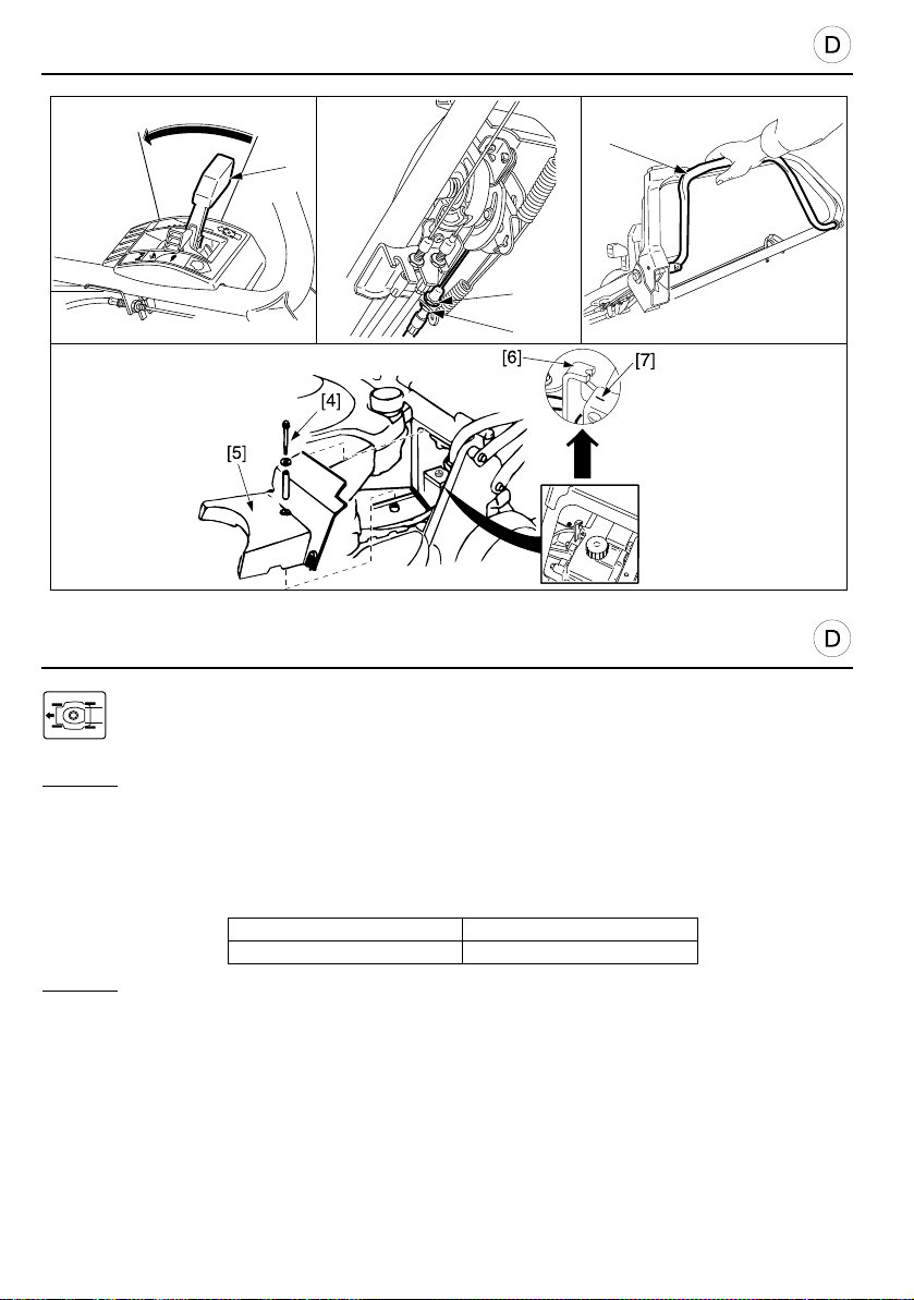
WARTUNGSHINWEISE
STOP
[1]
HRH536
[2]
[3]
[3]
EINSTELLUNG DES BODENZUGES FÜR DIE
GESCHWINDIGKEITSVERSTELLUNG
HRD536
1. Den Schalthebel [1] auf die höchste Stufe stellen.
2. Die Sicherungsmuttern [3] mit einem 10 mm Schlüssel lösen.
3. Anzieh en oder Lösen der Muttern [3] in der Weise, daß man ein Spiel von 1,5 mm bis
6,5 mm des Kupplungs- hebels [2] erhält, anschließend die Muttern wieder anziehen.
4. Den Motor anstellen und überprüfen, daß die Mindest- und Höchstgeschwindigkeiten
folgenden Werten entsprechen:
Mindestgeschwindigkeit 0 ~ 0,2 m/s
Maximal 1,4 m/s
HRH536
1. Das Messerwerk durch die Schnitthöhen- einstellhebel auf die höchtse Stufe stellen.
2. Schraube [4] und hintere Abdeckung [5] entfernen.
3. Schalthebel [1] auf die niedrigste Geschwindigkeit stellen und den Kupplungshebel [2]
betätigen.
4. Prüfen, ob die Kerbe auf dem Hebel [6] mit der Index-Markierung [7] auf dem Gehäuse, wie
gezeigt, eine Linie bildet.
5. Ist eine Einstellung erforderlich, so ist in dieser Stellung die Einstellschraube solange zu
drehen, der Muttern [3] lösen.
6. Den Motor starten und den Schalthebel betätigen, um zu prüfen, ob das Getriebe
einwandfrei schaltet.
7. Vergewissern Sie sich bei anbringen der Antriebswellen-Abdeckung, daß die
Befestigungsklammern fest eingerastet sind.
58
Page 59
MAINTENANCE
SHIFT LEVER ADJUSTMENT
HRD536
1. Put the shift lever [1] in the fastest position.
2. Undo the lock nuts [3] with a 10 mm spanner.
3. Tighten or undo the nuts [3] so as to obtain a clearance of between 1.5 mm and 6.5 mm at
the clutch lever [2], then tighten the nuts.
4. Start the engine and check that the minimum and maximum speeds correspond to the
following values:
Minimum 0 ~ 0.2 m/s
Maximum 1.4 m/s
HRH536
1. Raise the cutter deck by using the cutting height adjusting lever.
2. Remove the screws [4] and rear cover [5].
3. Position the shift lever [1] to minimum speed, and engage the drive clutch lever [2] as it is.
4. Make sure that slot [6] of the control arm aligning with index mark [7] of the case as shown.
5. If adjustment is necessary, keep the levers in this position, undo and adjust the nuts [3].
6. Start the engine and operate the shift lever. Check to ensure the transmission i s shifting
smoothly.
7. When installing the drive shaft cover, be sure that the claws of the cover are located
securely.
ENTRETIEN
RÉGLAGE DU LEVIER DE CHANGEMENT DE VITESSE
HRD536
1. Placer le levier de changement de vitesse [1] sur la position la plus rapide.
2. Desserrer les écrous de blocage [3] avec une clé de 10 mm.
3. Visser ou dévisser les écrous [3] de façon à obtenir un jeu de 1,5 mm à 6,5 mm au levier
d’embrayage [2], puis resserrer les éc rous.
4. Mettre le moteur en marche et vérifier que les vitesses minimale et maximale correspondent
aux valeurs suivantes :
Minimale 0 ~ 0,2 m/s
Maximale 1,4 m/s
HRH536
1. Remonter le carter de coupe à l’aide des leviers de réglage de hauteur de coupe.
2. Démonter les vis [4] et le couvercle arrière [5].
3. Positionner le levier de changement de vitesse [1] sur le minimum et engager le levier
d’embrayage d’avance ment [2] .
4. Vérifier que l’encoche [6] et la marque [7] soient bien alignées.
5. Si un réglage est nécessaire, maintenir les leviers dans cette position, desserrer et ajuster
les écrous [3].
6. Mettre le moteur en marche et manœuvrer le levier de changement de vitesse. Bien
s’assurer que la transmission se fait sans à-coups.
7. Remettre le couvercle en place en veillant à la position des ergots.
59
Page 60
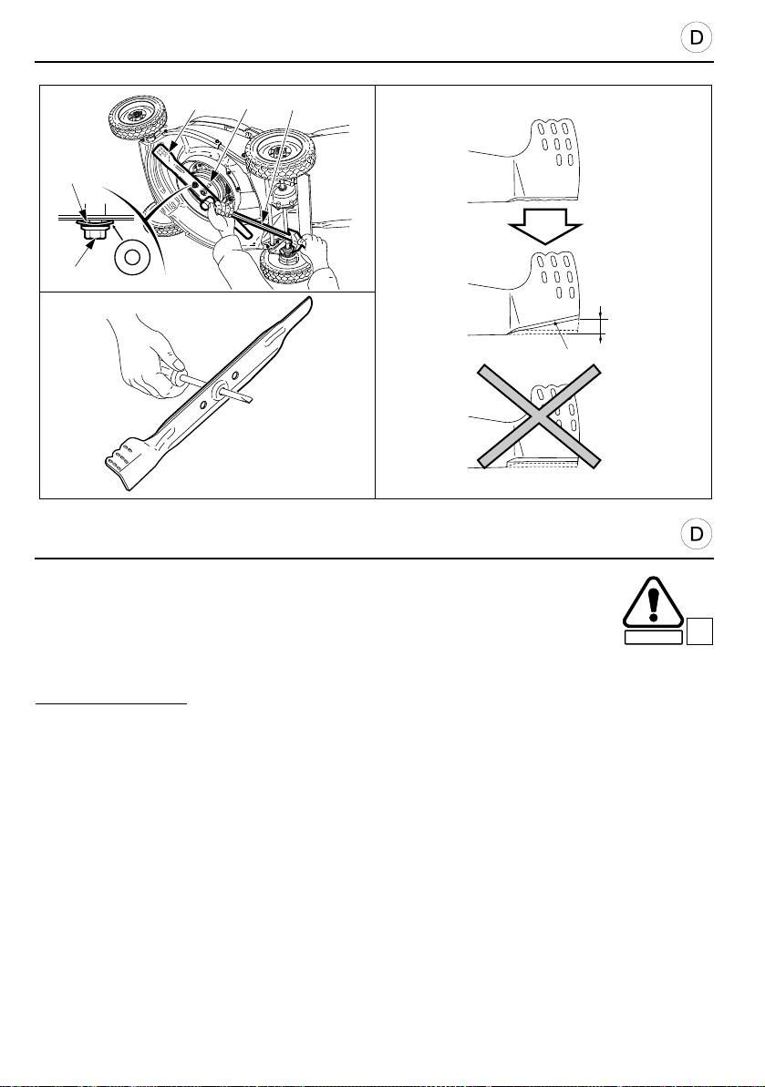
WARTUNGSHINWEISE
VORSICHT:
U
T
O
[2] [4] [5]
[1]
[3]
MAX
15 mm
[6]
SICHERHEIT
MESSER
MESSER-AUSBAU
1. Gashebel in STOPP-Stellung bringen.
2. Schließen Sie den Benzinhahn und entleeren Sie den Vergaser.
3. Rasenmäher nach rechts kippen, sodaß der Vergaser oben liegt.
ZUR BEACHTUNG:
schwierig.
4. Messer [2] mit Holzklotz am Drehen hindern und beide Klingen Befestigungs- schrauben [3]
mit Steckschlüssel 14 mm herausdrehen [5].
5. Das Messer aus seiner Halterung [4] abnehmen und die Lagersperre entfernen.
NACHSCHLEIFEN DES MESSERS
1. Die Schneidkanten des Messers mit einer F eile schärfen. Nur die obere Sei te feilen. Den
ursprünglichen Schnittwinkel beibehalten, um eine scharfe Schneidkante zu erhalten. Beide
Seiten gleichmäßig abfeilen, damit das Messer ausgewuchtet bleibt.
2. Nach dem Schärfen die Auswuchtung des Messers mit einem Schraubendreher wie gezeigt
testen. Wenn eine Seite leicht unter die Horizontale sinkt, diese Seite nachfeilen. Das
Messer auswechseln, wenn das Ungleichgewicht zu groß ist.
• Die Auswuchten des Messers ist entscheidend für gute Leistungen des Rasenmähers.
Ersetzen Sie alle Messer, die beschädigt sind oder eine Unwucht aufwelsen.
• Verwenden Sie nur Original-Honda-Ersatzmesser.
60
Nie den Rasenmäher nach links kippen, der folgende Neustart wäre
B3
Page 61
PRÉCAUTION :
SECURITE
B3
MAINTENANCE
CAUTION:
CUTTING BLADE
BLADE REMOVAL
1. Place the throttle control lever in “STOP” position.
2. Close the fuel shut-off valve and drain the carburettor.
3. Tip the mower so that the carburettor faces upwards.
Never tip the mower so that the carburettor faces down ; this will make starting difficult.
NOTE:
4. Remove the blade [2] bolts [3] with a 14 mm socket spanner [5]. Use a block of wood to
prevent the blade from turning when undoing the bolts.
5. Remove the blade from the blade holder [4] together with the block.
SAFETY
BLADE SHARPENING
1. Sharpen the blade cutting edges with a file. File the to p side only. Maintain the original
bevel [6] for a fine cutting edge. File both ends evenly to maintain blade balance.
2. After sharpening, test the blade’s balance using a screwdriver as shown. If either side dips
slightly below the horizontal, file that side. Replace the blade if it dips excessively.
• Blade balance is critical to proper mower performance. Replace any blade that is damaged or
out of balance.
• Use only a genuine Honda replacement blade or equivalent.
B3
ENTRETIEN
LAME DE COUPE
DÉMONTAGE DE LA LAME
1. Mettre la manette de commande des gaz sur “ARRÊT”.
2. Fermer le robinet d’essence et vidanger le carburateur.
3. Pencher la tondeuse de façon à ce que le carburateur soit orienté vers le haut.
Ne jamais incliner la tondeuse de façon à ce que le carburateur soit orienté vers le bas ;
NOTE :
il en résulterait un redémarrage difficile.
4. Retirer les vis [3] de lame [2] avec une clé à douille de 14 mm [5]. Utiliser un bloc en bois
pour empêcher la lame de tourner lors du desserrage des vis.
5. Retirer la lame du porte-lame [4] ainsi que la cale de roulement.
AFFÛTAGE DE LA LAME
1. Affûter les bords tranchants de la lame avec une lime. N’affûter que le bord supérieur.
Conserver le biseau d’origine [6] afin d’avoir une arête coupante très acérée. Il est
recommandé d’aiguiser les deux extrémités de manière égale, afin de maintenir l’équilibre
de la lame.
2. Après l’affûtage, vérifier l’équilibre de la lame en utilisant un tournevis comme illustré. Si l’un
ou l’autre des bords penche légèrement sous l’horizontale, il faut à nouveau aiguiser ce
côté.
• L’équilibre de la lame est essentiel pour obtenir de bonnes performanc es de coupe. Il faut
donc changer toute lame qui serait endommagée ou dont l’équilibre ne peut être rétabli.
• N’utiliser qu’une lame de rechange d’origine Honda.
61
Page 62
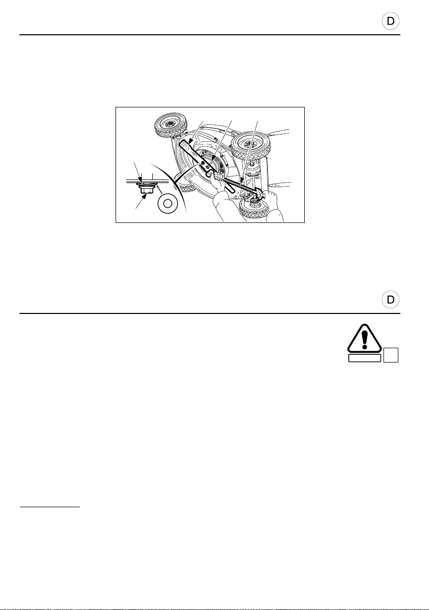
WARTUNGSHINWEISE
VORSICHT:
VORSICHT:
SICHERHEIT
B3
[1]
[3]
[2] [4] [5]
U
T
O
MESSER-EINBAU
1. Entfernen Sie Schmutz und Gras von den Befestigungsteilen.
2. Bringen Sie die Beilagscheibe so an, daß der Außendurchmesser auf dem Flansch aufliegt
(HRH536).
3. Befestigen Sie das Schneidwerkzeug mit den beiden Schrauben [3] und den
Spezialscheiben [1]. Die “OUT”-Markierung der Scheiben muß zum Schraubenkopf zeigen.
• Das Messer dreht sich im Uhrzeigersinn. Bauen Sie das Messer so ein, daß die Schrägen der
Messer zum Mähdeck zeigen.
• Messerschrauben und -Sprengringe sind Spezialteile; bitte nicht durch irgendwelche
Schrauben ersetzen!
4. Befestigen Sie die Messerverschraubungen mit einem Drehmomentschlüssel. Benutzen
Sie ein Holzstück, um zu verhindern, daß sich das Messer während des verschraubens
dreht.
Drehmoment:
49 - 59 N.m
• Fall Ihnen die erforderlichen Werkzeuge [5] fehlen, lassen Sie die Arbeiten von einem HondaHändler durchführen.
• Sollten die Befestigungsschrauben zu fest oder zu locker sein, kann das Messer brechen
oder sich lösen.
62
Page 63
PRÉCAUTION :
PRÉCAUTION :
SECURITE
B3
MAINTENANCE
CAUTION:
CAUTION:
B3
BLADE FITTING
SAFETY
1. Clean the dirt and grass from around the blade assembly area.
2. Install the flange of the bearing shim against the bearing (HRH536).
3. Fit blade [2] using the two bolts [3] and special washers [1] as shown. Fit the special washers
with their convex side, marked “OUT”, facing the bolts.
• Viewed from below, the blade turns counterclockwise. When reinstalling, place the blade so
its cutting edges face this direction of rotation (punched reference oriented against blade
holder).
• The blade bolts are specially designed for this purpose. Do not use other screws.
4. Retighten the blade bolts using a torque wrench. Use a wood block to stop the blade rotating
when tightening the screws.
Blade bolt tightening torque:
49 to 59 N.m
• If you do not have the required sharpening equipment or a torque wrench [5 ], ask your
approved Honda dealer to tighten the blade bolts for you before you use the mower.
• If the blade bolts are too tight or too slack, they may break or unscrew.
ENTRETIEN
MONTAGE DE LA LAME
1. Nettoyer la saleté et l’herbe se trouvant autour de la zone de montage de la lame.
2. Installer la cale de roulement avec sa colerette positionnée contre le roulement (HRH536).
3. Installer la lame [2] en utilisant les deux vis [3] et les rondelles spéciales [1] comme illustré.
Monter les rondelles spéciales avec le côté convexe marqué “OUT” tourné vers les vis.
• Vue comme ci-dessus, la lame tourne dans le sens inverse des aiguilles d’une montre. Lors
du remontage, placer la lame de manière à ce que les arêtes tranchantes soient face à la
direction de rotation (référence gravée tournée contre le support de lame).
• Les vis de lames sont spécialement conçues pour cet usage. Ne pas utiliser d’autres vis que
celles d’origine.
4. Resserrer les vis de lame avec une clé dynamométrique. Utilise r un bloc de bois pour
empêcher la lame de tourner lors du resserrage des vis.
Couple de serrage pour les vis de lame :
49 à 59 N.m
• Si vous ne disposez pas de l’équipement nécessaire à l’affûtage et de clé
dynamométrique [5], faites réaliser l’affûtage et resserrer les vis de lame par un
concessionnaire Honda agréé.
• Des vis de lame trop ou trop peu serrées peuvent se briser ou se dévisser.
63
Page 64
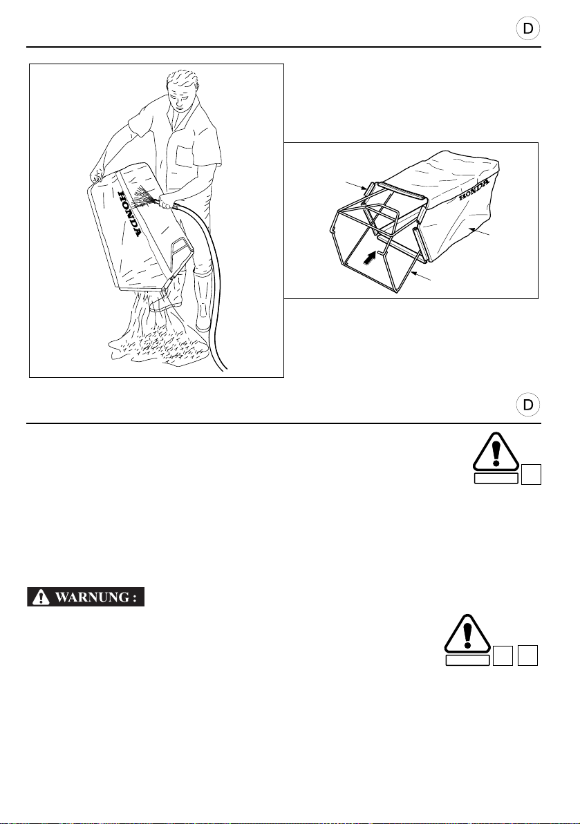
WARTUNGSHINWEISE
VORSICHT:
SICHERHEIT
C11
D6
SICHERHEIT
[1]
[2]
[3]
GRASSACK PFLEGE UND ERNEUERUNG
SÄUBERN DES SACKS
• Den Sack nie mit Hochdruck Kalt- oder Heißwasser reinigen, Beschädigungsgefahr.
• Ein Sack mit verstopften Maschen, hat einen zu hohen Luftwiderstand und das Mähgut kann
dann nicht mehr mit dem nötigen Luftdruck in den Sack befördert werden: es bleibt Gras auf
dem Rasen liegen, obwohl der Sack noch nicht ganz voll ist.
• Die Reinigung des abgenommenen Sacks erfolgt mit einem normalen Gartenschlauch. Man
spritzt den Sack von außen so ab, daß die Gras- und Erdreste den Sack durch die Füll- und
Entleeröffnung verlassen (nicht durch die Maschen!).
Ein Loch im Grassack muß entweder sofort geflickt oder der
Grassack erneuert werden. Vom Messer aufgewirbelte Steine,
Holzstückchen oder andere harte Gegenstände könnten durch das
Loch aus dem Grassack herausfliegen und Verletzungen
verursachen.
ERNEUERN DES GRASSACKS
Auch bei normalem Betrieb nützt sich der Grassack im Lauf der Zeit ab. Deshalb muß er ab und
zu auf Löcher und Ausfransen untersucht werden. Abgenutzten Sack nur durch neuen Original
Honda Sack ersetzen!
1. Plastikklemmen [1] abnehmen und alten Sack [2] vom Rahmen [3] entfernen.
2. Einen neuen Sack wie auf Seite 18 der vorliegenden Bedienungsanleitung angegeben,
anbringen.
64
B3
Page 65
PRÉCAUTION :
SECURITE
B3
SECURITE
C11
D6
MAINTENANCE
CAUTION:
C11
D6
SAFETY
GRASS BAG CLEANING AND REPLACEMENT
BAG CLEANING
• Washing with a high pressure water or steam je t will damage th e bag.
• Blocked mesh will prevent the grass from entering the bag.
• To clean the bag, we recommend washing it using a water jet directed from the outside to the
inside of the bag. The bag must be completely dry before bei ng used again. If the bag is
damp, it will become clogged very quickly.
Objects struck by the blade may be thrown through a torn or damaged
grass bag. Objects thrown out by the blade can cause serious injuries.
Always replace a torn or damaged grass bag.
SAFETY
BAG REPLACEMENT
The grass bag tends to wear even in normal conditions of use. Regularly check that it is no t
frayed or torn. Replace a damaged bag only by a genuine Honda replacement bag.
1. Detach the plastic edges [1] of the worn bag [2] and remove the bag frame [3].
2. Fit a new bag, following the instructions on page 19 of this manual.
B3
ENTRETIEN
NETTOYAGE ET CHANGEMENT DU SAC DE RAMASSAGE
NETTOYAGE DU SAC
• Un lavage au jet de vapeur ou à haute pression endommagera le sac.
• Des mailles obstruées empêchent l’herbe de pénétrer dans le sac.
• Pour nettoyer le sac, il est recommandé de le laver au jet d’eau dirigé de l’extérieur vers
l’intérieur. Il doit être bien sec avant de l’utiliser à nouveau. Si le sac est mouillé, il se
colmatera très rapidement.
Des objets frappés par la lame peuvent être projetés à travers un sac
à herbe déchiré ou abîmé. Des obj e ts projetés peuvent provoquer de
graves blessures. Remplacez un sac à herbe déchiré ou abîmé.
CHANGEMENT DU SAC
Même dans des conditions normales d’utilisation, le sac de ramassage a tendance à s’user. Il
convient donc de vérifier régulièrement s’il n’est pas effiloché ou déchiré. Ne remplacer un sac
détérioré que par un sac Honda d’origine.
1. Déclipser les bords en plastique [1] et retirer le sac usé [2] du cadre [3].
2. Monter un sac neuf en suivant les instructions de la page 19 de ce manuel.
65
Page 66
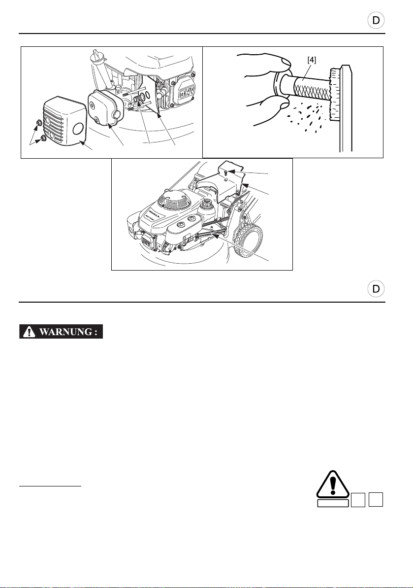
WARTUNGSHINWEISE
SICHERHEIT
C18
D7
[6 ]
[7 ]
[8 ]
[1]
[3]
[2]
[5]
[4]
FUNKENFÄNGER (Sonderzubehör)
Nach dem Betrieb den Rasenmäher erst abkühlen lassen; Verbrennungsgefahr am
heißen Auspufftopf!
In einigen Ländern ist es verboten, den Motor ohne Funkenfänger zu betreiben. Bitte
erkundigen Sie sich vor Gebrauch des Mähers nach den nationalen Vorschriften.
Funkenfänger sind als Zubehö r bei Ih rem Honda- Händler er hältlich.
1. Beide Muttern [1] mit 10 mm Schlüssel lösen.
2. Auspuffschutz [2], Auspufftopf [3] und Isolierplatte [5] entfernen.
3. Funkenfänger [4] vorsichtig herausnehmen, ohne das Gitter zu beschädigen.
4. Wenn erforderlich, schwarz-braune Verbrennungsrückstände von Funkenfänger und
Auspuffmündung abbürsten.
5. Funkenfänger wieder in den Auspuff einsetzen.
6. Die abgenommenen Teile in umgekehrter Reihenfolge wieder zusammenbauen.
7. Muttern [1] fest anziehen.
ANTRIEBSRIEMEN
HRD536: Typ H
1. Den Gashebel auf die Position “STOPP” bringen.
2. Die Schraube [6] mit einem 10 mm Schlüssel lösen und entfernen.
3. Das Schutzgehäuse [7] entfernen.
4. Den Antriebsriemen [8] auf seiner gesamten Länge überprüfen, wobei er durch Ziehen des
Starters vorwärts bewegt wird. Falls der Antriebsriemen Beschädigungen aufweist, muß er
von einem Honda-Fachhändler ersetzt werden.
5. Das Schutzgehäuse wieder anbringen und die Befestigungsschraube anziehen.
66
Page 67

C18
D7
MAINTENANCE
C18
D7
SPARK ARRESTER (optional part)
If the mower has just been run, the muffler will still be very hot. Allow it to cool down
before carrying out this operation.
In some regions, it is prohibited to operate an engine witho ut a spark arrester. Check
local regulations before using your mower. A spark arrester is available on option from
Honda dealers.
1. Unscrew and remove the two nuts [1] using a 10 mm socket wrench.
2. Remove the muffler guard [2] and the muffler [3], then the insulation [5].
3. Remove the spark arrester [4], taking care not to damage the grille.
4. If necessary, clean the carbon deposits from around the exhaust port and spark arrester.
5. Refit the spark arrester in the muffler.
6. Refit the insulation, the muffler and the muffler guard.
7. Fully retighten the two 10 mm nuts [1].
DRIVE BELT
HRD536: Type H
1. Move the throttle control lever to the “STOP” position.
2. Undo and remove the screw [6] using a 10 mm pipe spanner.
3. Remove the protective casing [7].
4. Inspect the belt [8] over its entire length. It can be moved by pulling the starter cord. If the belt
is damaged, have it replaced by an approved Honda dealer.
5. Refit the protective casing, and tighten the fixing screws.
SAFETY
ENTRETIEN
PARE-ÉTINCELLES (pièce en option)
Si la tondeuse vient de fonctionner, le pot d’échappemen t sera encore très chaud. Le
laisser refroidir avant de procéder à cette opération.
Dans certaines régions, il est interdit de faire fonctionner un moteur sans un pareétincelles. Étudier les réglementations locales avant d’utiliser votre tondeuse. Un pareétincelles en option est disponible auprès de votre concessionnaire Honda.
1. Desserrer et déposer les deux écrous [1] à l’aide d’une clé à pipe de 10 mm.
2. Retirer le protecteur de pot d’échappement [2], le pot d’échappement [3] puis l’isolant [5].
3. Déposer le pare-étincelles [4] en prenant soin de ne pas endommager la grille.
4. Nettoyer, si nécessaire, la calamine déposée autour de l’orifice d’échappement et du pare-
étincelles.
5. Remettre le pare-étincelles en place dans le pot d’échappement.
6. Remonter l’isolant, le pot d’échappement et la protection de pot d’échappement.
7. Resserrer à fond les deux écrous de 10 mm [1].
COURROIE DE TRANSMISSION
HRD536 : Type H
1. Amener la manette des gaz sur la position “ARRÊT”.
2. Desserrer et déposer la vis [6] à l’aide d’une clé à pipe de 10 mm.
3. Déposer le carter de protection [7].
4. Inspecter la courroie [8] sur toute sa longueur, son déplacement est obtenu en tirant sur le
lanceur. En cas de détérioration apparente de la courroie, la faire remplacer par un
concessionnaire agréé Honda.
5. Remettre le carter de protection en place, et resse rrer la vis de fixa tion.
SECURITE
67
Page 68
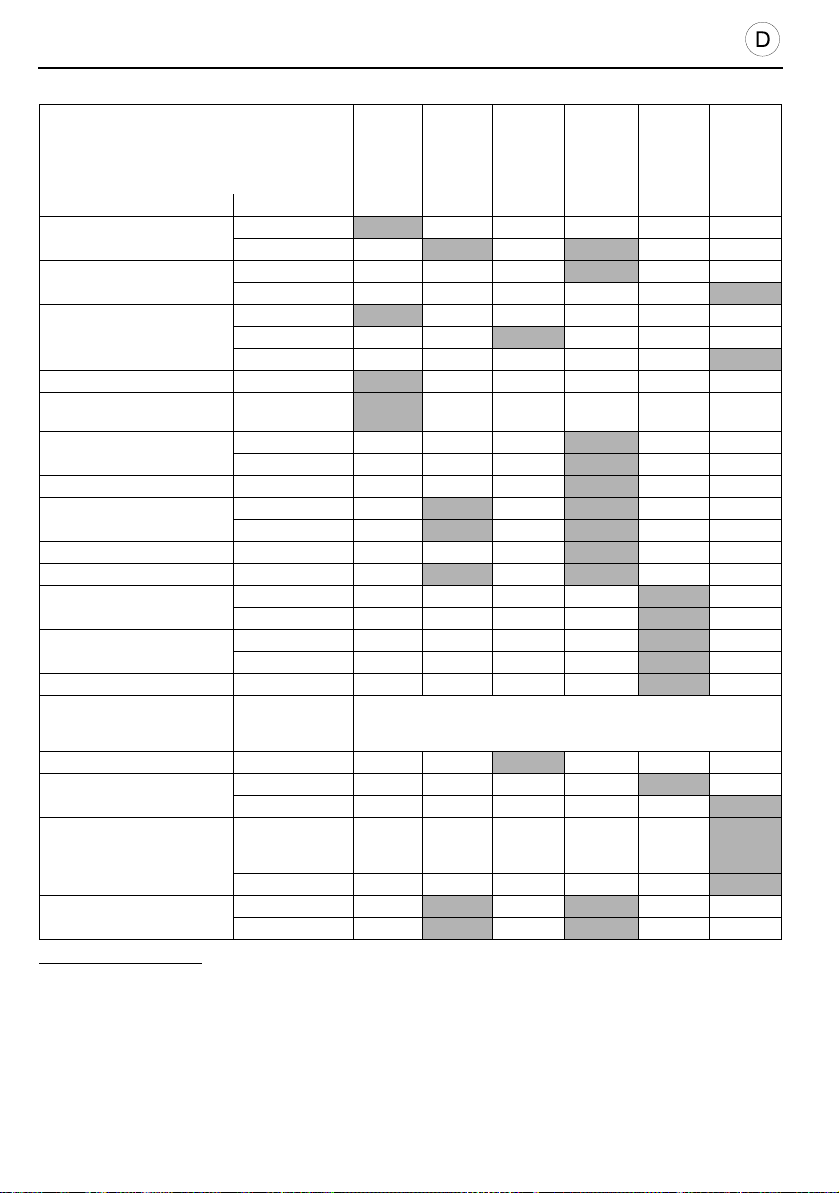
WARTUNGSHINWEISE
WARTUNGSPLAN
HÄUFIGKEIT
Die Wartung muß in folgenden Zeitabständen
ausgeführt werden, die in Monaten oder
Betriebsstunden angegeben sind und bei denen
jeweils das kürzere Intervall magebend ist (5).
Bauteil Aktion
Motoröl
Getriebeöl
Luftfilter
Grasfangsack Reinigen
Messerschrauben und
Messerzustand
Zündkerze
Funkenfänger (Zubehörteil) Reinigen
Seilzug der
Messerkupplung
Messerkupplung Prüfen (2)
Getriebezug (3) Nachstellen
Gas zug
Ventilspiel
Kraftstofftank und Filter Reinigen
Kraftstoffleitung
Batterie (3) Nachladen
Antriebsriemen (3)
Hintere Rollenlager (3)
Seilzug der Messerkupplung
Ölstand prüfen
Wechseln
Ölstand prüfen
Wechseln
Prüfen
Reinigen (1)
Wechseln
Prüfen
Prüfen
Reinigen
Prüfen
Nachstellen
Prüfen
Nachstellen
Prüfen
Nachstellen
Prüfen (und
nötigenfalls
wechseln)
Prüfen
Auswechseln (2)
Prüfen (und
nötigenfalls
wechseln)
Fett wechseln (2)
Kontrolle
Nachstellen
Vor jeder
Inbetrie-
nahme
ZUR BEACHTUNG:
(1) Bei Lagerung an staubigen Orten sind die Intervalle zu verkürzen.
(2) Diese Teile müssen von einem Honda-Vertragshändler gewartet werden, außer wenn der Besitzer
über die passenden Werkzeuge und über die entsprechenden Kenntnisse verfügt. Siehe Honda-
Händlerverzeichnis.
(3) Gegebenenfalls.
(4) Während der Lagerung.
(5) Bei professionellem Einsatz. Betriebsstundenbuch zur Bestimmung der genauen
Hauptserviceintervalle führen.
* Für HRH536.
Für Q typen.
Nach 1
Monat
bzw.
20
Stunden
Nach 3
Monaten
bzw.
50
Stunden
Alle 2 Jahre (2)
(4)
Nach 6
Monaten
bzw.
100
Stunden
(2)*
Jährlich
bzw.
nach
300
Stunden
(2)
(2)
(2)
Alle Jahre
oder
1000
Stunden
(2)*
(1)
(2)
68
Page 69
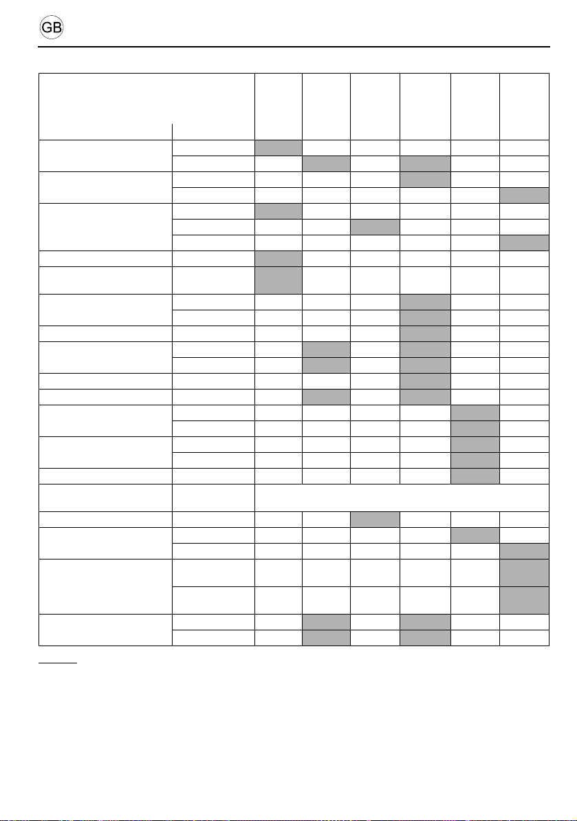
MAINTENANCE
MAINTENANCE SCHEDULE
FREQUENCY
Maintenance to be carried out at the intervals
indicated in months or in operating hours which
ever occurs first (5)
Item Intervention
Engine oil
Transmission oil
Air cleaner element
Grass bag Clean
Blade screw tightness and
blade condition
Spark plug
Spark arrester (optional part) Clean
ROTOSTOP cable
ROTOSTOP Check (2)
Shift cable (3) Adjust
Throttle cable
Valve clearance
Fuel tank and filter Clean
Fuel lines
Batterie (3) Recharge
Drive belt (3)
Rear roller bearing (3)
Drive clutch lever cable
Check level
Change
Check level
Change
Check
Clean (1)
Change
Check
Check
Clean
Check
Adjust
Check
Adjust
Check
Adjust
Check (replace
if necessary)
Check
Change (2)
Check (replace
if necessary)
Change the
grease
Check
Adjust
Each
use
NOTE:
(1) Increase cleaning frequency when mower is used in dusty areas.
(2) Maintenance of these points must be carried out by a Honda dealer unless the user has the
necessary tools and mechanical experience. See Honda Shop Manual.
(3) If applicable.
(4) During storage.
(5) For professional commercial use, log hours of operation to determine proper maintenance intervals.
* For HRH536.
For Q types.
First
month
or
20 hours
Every
3 months
50 hours
6 months
or
100 hours
Every 2 years (2)
(4)
Every
or
(2)*
Every
year or
300
hours
(2)
(2)
(2)
Every
year or
1000
hours
(2)*
(1)
(2)
(2)
69
Page 70
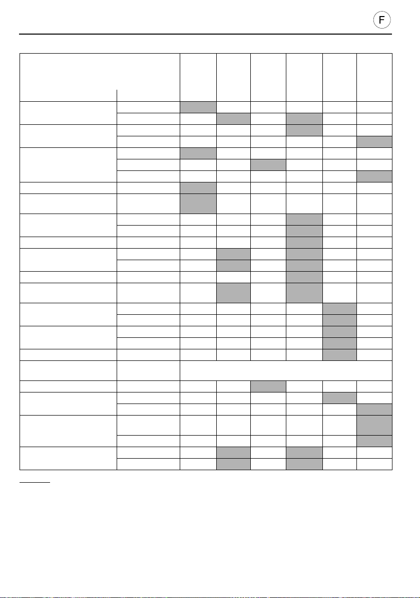
ENTRETIEN
CALENDRIER D’ENTRETIEN
PÉRIODICITÉ
Entretien à effectuer aux intervalles indiqués en
mois ou en heures de fonctionnement, en retena nt
l’intervalle le plus court (5).
Élément Intervention
Huile moteur
Huile de transmission
Filtre à air
Sac de ramassage Nettoyer
Serrage des vis de la lame
et état de la lame
Bougie d’allumage
Pare-étincelles (en option) Nettoyer
Câble de ROTOSTOP
ROTOSTOP Vérifier (2)
Câble de changement de
vitesse (3)
Câble de commande
des gaz
Jeu aux soupapes
Réservoir d’essence et filtre Nettoyer
Tuyauterie d’essence
Batterie (3) Recharger
Courroie de transmission (3)
Roulement des rouleaux
arrières (3)
Câble d'embrayage
d'avancement
Contrôler le niveau
Renouveler
Contrôler le niveau
Renouveler
Vérifier
Nettoyer (1)
Changer
Vérifier
Vérifier
Nettoyer
Vérifier
Régler
Régler
Vérifier
Régler
Vérifier
Régler
Vérifier (remplacer
si nécessaire)
Vérifier
Changer (2)
Vérifier (remplacer
si nécessaire)
Changer la graisse (2)
Vérifier
Régler
chaque
utilisation
NOTE :
(1) Augmenter la fréquence de nettoyage en cas d’utilisation dans des zones poussiéreuses.
(2) L’entretien de ces points doit être confié à un concessionnaire agréé Honda, à moins que l’utilisateur
ne dispose des outils nécessaires et ne soit mécaniquement compétent. Se reporter au Manuel
d’Atelier Honda.
(3) Modèles concernés.
(4) Pendant le remisage.
(5) Pour les machines à usage professionnel, noter les heures de fonctionnement afin de respecter les
intervalles d’entretien.
* Pour HRH536.
Pour les types Q.
70
Après
A
1 mois
ou après
20 h
Tous les
3 mois ou
toutes les
Tous les 2 ans (2)
50 h
(4)
Tous les
6 mois ou
toutes les
100 h
(2)*
Tous les
ans ou
toutes
les 300 h
(2)
(2)
(2)
Tous les
ans ou
toutes les
1000 h
(2)*
(1)
(2)
Page 71

Störung Mögliche Ursache Seite
Motor springt nicht an:
STÖRUNGSBESEITIGUNG
1.
Kein Benzin im Tank.
Der Gashebel befindet sich in Position
2.
“STOPP”.
3.
Der Benzinhahn ist geschlossen.
Zündkabel nicht mit Kerze verbunden oder
4.
schlecht am Stecker befestigt.
Zündkerze verrußt oder beschädigt oder
5.
Elektrodenabstand falsch.
6.
Der Motor ist “abgesoffen”.
20
32
32
-
50
34
Motor springt nicht sofort an
oder hat zu wenig Leistung:
Motor stottert:
Motor wird sehr heiß:
Der Rasenmäher vibriert sehr
stark:
1.
Schmutz im Benzintank.
2.
Luftfilter verschmutzt.
3.
Wasser im Benzintank oder im Vergaser.
Tankentlüftung oder Vergaser sind
4.
verstopft.
Zündkerze verrußt oder
1.
Elektrodenabstand falsch.
2.
Luftfilter verschmutzt.
1.
Zündkerzen-Elektrodenabstand falsch.
2.
Luftfilter verschmutzt.
Kühlrippen des Zylinderkopfes
3.
verschmutzt.
4.
Zu wenig Öl im Motor.
Das Schmutz-Gitter der Schwungscheibe,
5.
welches sich unter dem Reversier-Starter
befindet, ist...
Messerbefestigung locker
1.
Motorblockbefestigung locker.
Das Messer hat durch Bruch oder falsches
2.
Nachschleifen dynamische Unwucht:
Messer auswechseln.
-
48
-
-
50
48
50
48
-
28
-
60
60
71
Page 72

TROUBLESHOOTING
Incident Probable cause Page
Engine does not start:
1.
2.
3.
4.
5.
6.
No fuel.
The throttle control lever is in the “STOP”
position.
Fuel shut-off valve is closed.
Spark plug cord incorrectly attached or
disconnected.
Spark plug defective or incorrect electrode gap.
Engine flooded.
21
33
33
-
51
35
Hard starting or loss of
power:
Erratic operation:
Engine overheats:
Excessive vibration:
1.
Dirt in petrol tank.
2.
The air cleaner is dirty.
3.
Water in petrol tank and carburettor.
4.
Vent in fuel cap and/or carburettor clogged.
1.
Spark plug faulty or improperly gapped.
2.
The air cleaner is dirty.
1.
Spark plug improperly gapped.
2.
The air cleaner is dirty.
3.
Dirty cooling fins.
4.
Low oil level.
The flywheel’s protector grid, located under the
5.
recoil starter, is restricted by blades of grass,
etc..
1.
Loose blade or engine mounting bolts.
2.
Blade unbalanced.
-
49
-
-
51
49
51
49
-
29
-
61
61
72
Page 73

Incident Cause probable Page
Le moteur ne démarre pas :
DÉPISTAGE DES PANNES
1.
Il n’y a pas d’essence.
Le levier de commande des gaz se trouve sur
2.
la position “ARRÊT”.
3.
Le robinet d’arrivée d’essence est fermé.
Le fil de la bougie d’allumage est mal fixé ou
4.
débranché.
La bougie d’allumage est défectueuse ou
5.
l’écartement des électrodes est incorrect.
6.
Le moteur est noyé.
21
33
33
-
51
35
Le démarrage est difficile ou il y
a perte de puissance :
Le fonctionnement est
irrégulier :
Le moteur chauffe
anormalement :
La tondeuse vibre de manière
excessive :
Il y a des impuretés dans le réservoir
1.
d’essence.
2.
Le filtre à air est sale.
Il y a de l’eau dans le réservoir d’essence ainsi
3.
que dans le carburateur.
L’évent dans le bouchon du réservoir
4.
d’essence et/ou le carburateur est encrassé.
La bougie d’allumage est défectueuse ou
1.
l’écartement des électrodes est incorrect.
2.
Le filtre à air est sale.
L’écartement des électrodes de la bougie
1.
d’allumage est incorrect.
2.
Le filtre à air est sale.
Les ailettes de refroidissement du moteur sont
3.
encrassées.
4.
Le niveau d’huile est insuffisant.
Accumulation d’herbe sur la grille protectrice
5.
située sous le lanceur à réenroulement.
Les vis de lame ou du moteur sont desserrées.
1.
2.
La lame est déséquilibrée.
-
49
-
-
51
49
51
49
-
29
-
61
61
73
Page 74
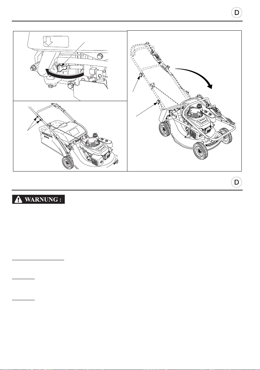
GERÄTETRANSPORT
[1]
[2]
[2]
[3]
[3]
Rasenmäher nicht gekippt transportieren. Es könnte Öl oder Benzin auslaufen,
Brandgefahr!
ZUM TRANSPORT DES RASENMÄHERS
1. Gashebel auf die “STOPP”-Position stellen.
2. Kerzenstecker abziehen.
3. Benzinhahn schließen.
Zur Erleichterung der Arbeit sollte der Grasfangsack entfernt werden (seihe Seite 18).
ZUR BEACHTUNG:
Seilzüge nicht geknickt oder zu stark gespannt sind.
HRH536
4. Betestigunsschrauben [1] herausnschmen und Führungsholme zusammenklappen.
HRD536
4. Lenkgestänge [3] zusammenklappen [3].
74
Beim Einknicken des Lenkgestänges ist darauf zu achten, daß die
Page 75

TRANSPORT
Do not tilt the mower since this may cause fuel or oil spillage ; spilt fuel or even fuel
vapours are a fire hazard.
TO TRANSPORT THE MOWER
1. Place the throttle control lever in “STOP” position.
2. Pull off the spark plug cap.
3. Close the fuel shut-off valve .
To facilitate the operation, remove the grass bag (see page 19).
When folding the handle, check that the cables are not knotted, twisted or too tight.
NOTE:
HRH536
4. Loosen the four fixing screw [1] to fold the handle.
HRD536
4. Unscrew the knobs [2], remove the screws and fold handle [3].
TRANSPORT
Pour ne pas risquer de répandre de l’essence ou de l’huile, ne pas incliner la tondeuse;
de l’essence répandue ou encore des vapeurs d’essence risquent de prendre feu.
POUR TRANSPORTER LA TONDEUSE
1. Mettre le levier de commande des gaz sur la position “ARRÊT”.
2. Enlever le capuchon de la bougie.
3. Fermer le robinet d’arrivée de carburant.
Pour plus de commodités, retirer le sac de ramassage (voir page 19).
Pendant le pliage du guidon, vérifier si les câbles ne sont pas noués, tordus ou encore
NOTE :
trop tendus.
HRH536
4. Démonter les quatre vis de fixation [1] pour déposer le guidon.
HRD536
4. Dévisser les molettes [2], retirer les vis et replier le guidon [3].
75
Page 76
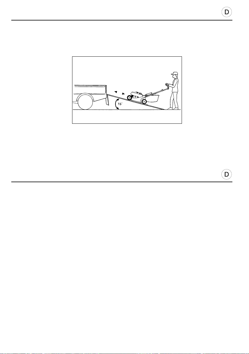
GERÄTETRANSPORT
VORSICHT:
VERLADEN DES RASENMÄHERS
• Auf- und Abladen des Rasenmähers nur bei stehendem Motor und nie mit eigenem
Radantrieb (Beschädigung durch Kontrollverlust über das Gerät).
• Beim Rückwärtsrollen des Rasenmähers Fahrkupplung nicht einlegen
(Beschädigungsgefahr des Radantriebs).
• Rasenmäher nur horizontal und auf allen vier Rädern stehend transportieren.
• Laderampe benutzen oder Helfer zum Einladen herbeiholen.
• Neigung der Laderampe nicht größer als 15°.
• Nach dem Einladen Keile unter die Räder schieben und Rasenmäher mit Transportgurten
gegen Verrutschen sichern.
• Die Transportgurte dürfen folgende Teile des Rasenmähers nicht berühren: Gashebel,
Messerkupplungsbügel, Benzintank, Bowdenzüge.
76
Page 77

PRÉCAUTION :
TRANSPORT
CAUTION:
LOADING THE MOWER
• To prevent losing control of or damaging the mower, do not use the drive system when going
up or down a loading ramp.
• To prevent damaging the drive system, do not engage the clutch when the mower is rolling
backwards.
• Transport the mower in normal horizontal position with its four wheels flat on the vehicle
platform.
• We recommend that you use a loading ramp or that you get someone to help you load and
unload the mower.
• Adjust the loading ramp so that it is inclined at an angle of less than 15°.
• When transporting the mower, immobilise it using straps and place chocks under the wheels.
• The straps must not touch the following parts of the mower: throttle control lever, blade clutch
lever, fuel tank and all the control cables.
TRANSPORT
CHARGEMENT DE LA TONDEUSE
• Pour éviter tout risque de perte de contrôle ou d’endommagement de la tondeuse, ne pas
utiliser le système de traction lorsque l’on fait monter ou descendre la tondeuse sur une
rampe de chargement.
• Pour éviter d’endommager le système de traction, ne pas enclencher l’embrayage lorsque la
tondeuse roule en marche arrière.
• Transporter la tondeuse en position horizontale normale, ses quatre roues à plat sur la plate-
forme du véhicule.
• Il est recommandé d’avoir recours à une rampe de chargement ou de se faire aider par
quelqu’un pour charger ou décharger la tondeuse.
• Régler la rampe de chargement de façon à ce que son angle d’inclinaison soit inférieur à 15°.
• Lorsque l’on transporte la tondeuse, l’immobiliser à l’aide de sangles et placer des cales sous
les roues.
• Les sangles ne doivent pas toucher les parties suivantes de la tondeuse : le levier de
commande des gaz, le levier de l’embrayage de lame, le réservoir d’essence, ainsi que
l’ensemble des câbles de commande.
77
Page 78
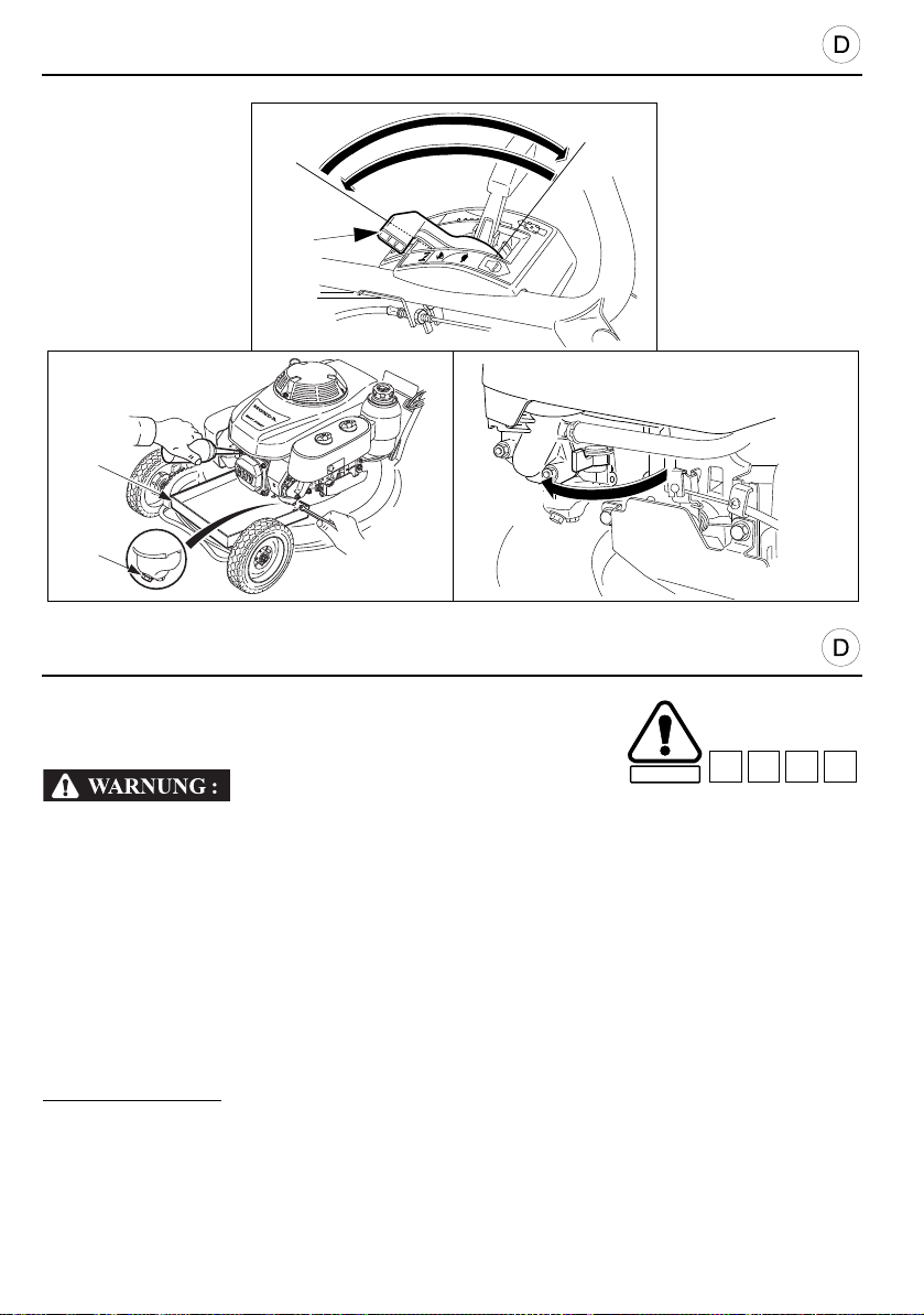
LÄNGERE AUßERBETRIEBSETZUNG
SICHERHEIT
D2 D3 D4B3
[2]
[1]
[A]
[4]
[3]
LÄNGERE AUßERBETRIEBSETZUNG
Wenn der Rasenmäher länger als 30 Tage nicht benützt wird,
zum Schutz der Bauteile folgende Wartung durchführen:
Benzintank nur entleeren, wenn Motor abgekühlt ist. Brandgefahr!
1. Den Kraftstoff aus dem Kraftstofftank und aus dem Vergaser in ein geeignetes Gefäß
ablassen [2]. Den Kraftstoffhahn öffnen.
a. Den Gashebel [4] in die “SCHNELL” [A] - Position stellen.
b. Die Ablaßschraube an der Schwimmerkammer lösen und den Kraftstoff ablassen [1].
c. Die Ablaßschraube wieder festzi ehen und Kraftstoffhahn schileßen [3].
2. Ölwechsel vornehmen (seihe Seite46).
3. Starterseilzug langsam bis zum starken Widerstand anziehen. Hiermit werden die
Zylinderventile geschlossen und vor Staub und Korrosion geschützt.
4. Blanke Metallteile (Messer) leicht ölen. Rasenmäher in trockenem, staubfreien Raum ggf.
unter Stoffdecke aufbewahren. Nicht unter Plastikhülle und nicht im Freien lagern:
Kondenswasserbildung, Rostgefahr.
ZUR BEACHTUNG:
ausschrauben und 5 bis 10 cm3 frisches Motoröl in den Zylinder gießen. Danach ohne
eingeschraubte Kerze Startseil langsam 3 mal ziehen, damit sich der Ölfilm verteilt Kerze
einschrauben und anziehen.
78
Zur Überwinterung oder zur Lagerung über mehr als 3 Monate Zündkerze
Page 79
SECURITE
D2 D3 D4B3
PREP ARATIONS FOR STORING THE MOWER
D2 D3 D4B3
Carry out the following operations to protect the mower each time
it is to be stored for a period of more than 30 days.
STORAGE
Do not drain the fuel tank while the muffler is hot.
1. Drain the fuel tank and the carburettor into a suitable receptacle [2].
a. Place the throttle control lever [4] in “FAST” position [A] and open the fuel shut-off valve.
b. Remove drain plug [1] to drain carburettor and fuel tank.
c. Refit the drain plug and close the fuel shut-off valve [3].
2. Change the engine oil (see page 47).
3. Pull the starter slowly until a resistance is felt. This closes the valves and protects them from
dust and corrosion.
4. Coat all surfaces liable to rust with a thin f ilm of oil. Co ver the mower an d store it on a flat
surface in a dry, dust free place. Do not use a plastic cover since this retains dampness.
If the mower is to be stored for a period of more than 3 months, remove the spark
NOTE:
SAFETY
plug and pour 5 to 10 cc of clean engine oil into the cylinder ; then pull the starter slowly
two or three times to spread the oil. Do not leave the mower lying on its side over long
periods. This may cause difficult starting and gear oil leaks.
REMISAGE
PRÉP ARATION POUR LE REMISAGE
Procéder aux opérations suivantes, afin de protéger la tondeuse
chaque fois qu’elle doit être remisée pour une période de plus de
30 jours.
Ne pas vidanger le réservoir d’essence alors que le pot d’échappement est ch aud.
1. Vidanger le réservoir d’essence et le carburateur dans un récipient adéquat [2] :
a. Mettre le levier de commande des gaz [4] sur la position “RAPIDE” [A].
b. Retirer la vis de vidange [1] pour vidanger le carburateur et le réservoir.
c. Revisser ensuite la vis et fermer le robinet d’arrivée d’essence [3].
2. Changer l’huile moteur (voir page 47).
3. Tirer le lanceur jusqu’à sentir une résistance. Cela permet de fermer les soupapes et de les
protéger de la poussière et de la corrosion.
4. Enduire d’un léger film d’huile les surfaces qui sont susceptibles de rouille r. Recouvrir la
tondeuse et la remiser sur un sol plan et dans un endroit sec, à l’abri de la poussière. Ne pas
utiliser de bâche en plastique qui retiendrait l’humidité.
Si la tondeuse doit être remisée pendant une période de plus de 3 mois, retirer la
NOTE :
bougie d’allumage et verser 5 à 10 cm3 d’huile moteur propre dans le cylindre, tirer ensuite
doucement deux ou trois fois le lanceur, afin de bien répartir l’huile. Ne pas laisser la
tondeuse couchée sur le côté pendant une longue période. Ceci peut être la cause d’un
démarrage difficile du moteur et d’une fuite de l’huile de transmission.
79
Page 80

LÄNGERE AUßERBETRIEBSETZUNG
WIEDERINBETRIEBNAHME NACH DER EINLAGERUNG
1. Die Zündkerze herausdrehen; sich vergewissern, daß sie sauber ist und daß der
Elektrodenabstand stimmt (seihe Seite 50). Das Anlasserseil mehrmals ziehen.
2. Die Zündkerze so weit wie möglich von Hand einschrauben, dann mit dem Schlüssel noch
um 1/8 bis 1/4 Umdrehung festziehen.
3. Den Ölstand im Motor nachprüfen, sich vergewissern, daß das Öl sauber ist (seihe Seite28).
4. Den Kraftstofftank auffüllen und den Motor anlassen.
ZUR BEACHTUNG:
Motor bei Inbetriebnahme einige Minuten lang sehr stark; das ist ganz normal.
80
Wenn zum Rostschutz Öl in den Zylinder gegeben wurde, raucht der
Page 81

STORAGE
USING THE MOWER AFTER A STORAGE PERIOD
1. Remove the spark plug, check that it is clean and that the electrode gap is correct. Pull the
starter several times (see page 51).
2. We recommend that the spark plug be screwed down as far as possible by hand until finger
tight ; then use a plug spanner to tighten it by an extra 1/8 or 1/4 turn.
3. Check the level and condition of the engine oil (see page29).
4. Fill the fuel tank and start the engine.
If the cylinder has been coated with oil, the engine will smoke on start-up. This is
NOTE:
normal.
REMISAGE
RÉUTILISA TION APRÈS REMISAGE
1. Retirer la bougie d’allumage, vérifier si elle est propre et si l’écartement des électrodes est
correct. Tirer le lanceur à plusieurs reprises (voir page51).
2. Il est recommandé de visser la bougie à la main aussi loin que possible ; puis se servir d’une
clé à bougie pour donner encore 1/8 à 1/4 de tour supplémentaire.
3. Vérifier le niveau et l’état de l’huile moteur (voir page 29).
4. Remplir le réservoir d’essence et mettre le moteur en marche.
Si le cylindre a été enduit d’huile, le moteur fumera au démarrage mais cela est normal.
NOTE :
81
Page 82

ADRESSEN / ADDRESSES / ADRESSES
Wenn Sie weitere Fragen haben, wenden Sie sich bitte unter der folgenden Adresse/
Telefonnummer an das Honda-Kundenbetreuungszentrum :
For further information, please contact Honda Customer Information Centre at the following
address or telephone number :
Pour toute information complémentaire, veuillez prendre contact avec le Service Relations
Consommateurs Honda à l’adresse ou au numéro de téléphone suivant :
AUSTRIA
Honda Motor Europe (North)
Hondastraße 1
2351 Wiener Neudorf
Tel. : +43 (0)2236 690 0
Fax : +43 (0)2236 690 480
http://www.honda.at
BELGIUM
Honda Motor Europe (North)
Doornveld 180-184
1731 Zellik
Tel. : 32 02 620 10 00
Fax : 32 02 620 10 01
http://www.honda.be
BULGARIA
Kirov Ltd.
49 Tsaritsa Yoana blvd
1324 Sofia
Tel. : +359 2 93 30 892
Fax : +359 2 93 30 814
http://www.kirov.net
CANARY ISLANDS
Automocion Canarias S.A.
Carretera General del Sur, KM. 8,8
38107 Santa Cruz de Tenerife
Tel. : + 34 (922) 620 617
Fax : +34 (922) 618 042
http://www.aucasa.com
CROATIA
Hongoldonia d.o.o.
Jelkovecka Cesta 5
10360 Sesvete – Zagreb
Tel. : +385 1 2002053
Fax : +385 1 2020754
http://www.hongoldonia.hr
CYPRUS
Alexander Dimitriou & Sons Ltd.
162 Yiammos Kramidiotis avenue
2235 Latsia, Nicosia
Tel. : + 357 22 715 300
Fax : + 357 22 715 400
82
CZECH REPUBLIC
BG Technik cs, a.s.
Honda Power Equipment
U Zavodiste 251/8
15900 Prague 5 - Velka Chuchle
Tel. : +420 2 838 70 850
Fax : +420 2 667 111 45
http://www.honda-stroje.cz
DENMARK
Tima Products A/S
Tårnfalkevej 16 - Postboks 511
2650 Hvidovre
Tel. : +45 36 34 25 50
Fax : +45 36 77 16 30
http://www.tima.dk
FINLAND
OY Brandt AB.
Tuupakantie 7B
01740 Vantaa
Tel. : +358 20 775 7200
Fax : +358 9 878 5276
http://www.brandt.fi
FRANCE
Honda Relations Clientèle
45146 St Jean de la Ruelle cedex
TSA 80627
Tel. 02 38 81 33 90
Fax. 02 38 81 33 91
http://www.honda.fr
relationsclientele.produits-
GERMANY
Honda Motor Europe (North) Gmbh
Sprendlinger Landstraße 166
63069 Offenbach am Main
Tel. : +49 69 8300 60
Fax : +49 69 8300 65100
http://www.honda.de
GREECE
General Automotive Co S.A.
71 Leoforos Athinon
10173 Athens
Tel. : +30 210 349 7809
Fax : +30 210 346 7329
http://www.honda.gr
HUNGARY
Motor.Pedo Co., Ltd.
2040 Budaors
Kamaraerdei út 3.
Tel. : +36 23 444 971
Fax : +36 23 444 972
http://www.hondakisgepek.hu
IRELAND
Two Wheels Ltd.
Crosslands Business Park
Ballymount Road
Dublin 12
Tel. : +353 01 460 2111
Fax : +353 01 456 6539
http://www.hondaireland.ie
ITALY
Honda Italia Industriale S.p.A.
Via della Cecchignola, 5/7
00143 Roma
Tel. : +848 846 632
Fax : +39 065 4928 400
http://www.hondaitalia.com
LATVIA
Bensons Auto
Kr.Valdemara Street 21, 646 office
Riga, 1010
Tel. : +371 7 808 333
Fax : +371 7 808 332
LITHUANIA
JP Motor Ltd
Kubiliaus str. 6
08234 Vilnius
Tel. : + 370 5 276 5259
Fax. : +370 5 276 5250
http://www.hondapower.lt
MALTA
The Associated Motors
Company Ltd.
New Street in San Gwakkin Road
Mriehel Bypass, Mriehel QRM17
Tel. : +356 21 498 561
Fax : +356 21 480 150
Page 83

ADRESSEN / ADDRESSES / ADRESSES
NETHERLANDS
Honda Motor Europe (North)
Afd. Power Equipment-Capronilaan 1
1119 NN Schiphol-Rijk
Tel. : +31 20 7070000
Fax : +31 20 7070001
http://www.honda.nl
NORWAY
Berema AS
P.O. Box 454
1401 Ski
Tel. : +47 64 86 05 00
Fax : +47 64 86 05 49
http://www.berema.no
POLAND
Aries Power Equipment Sp. z o.o.
ul. Wroclawska 25A
01-493 Warszawa
Tel. : +48 (22) 861 4301
Fax : +48 (22) 861 4302
http://www.hondapower.pl
PORTUGAL
Honda Portugal, S.A.
Abrunheira
2714-506 Sintra
Tel. : +351 21 915 53 33
Fax : +351 21 915 23 54
http://www.honda.pt
REPUBLIC OF BELARUS
Scanlink Ltd.
Kozlova Drive, 9
220037 Minsk
Tel. : +375 172 999 090
Fax : +375 172 999 900
ROMANIA
Hit Power Motor Srl
Calea Giulesti N° 6-8 Sector 6
060274 Bucuresti
Tel. : +40 21 637 04 58
Fax : +40 21 637 04 78
http://www.honda.ro
RUSSIA
Honda Motor Rus Llc
42/1-2, Bolshaya Yakimanka st.
117049, Moscow
Tel. : +74 95 745 20 80
Fax : +74 95 745 20 81
http://www.honda.co.ru
SERBIA & MONTENEGRO
Bazis Grupa d.o.o.
Grcica Milenka 39
11000 Belgrade
Tel. : +381 11 3820 300
Fax : +381 11 3820 301
http://www.hondadasrbija.co.yu
SLOVAKIA REPUBLIC
Honda Slovakia, spol. s r.o.
Prievozská 6 - 821 09 Bratislava
Slovak Republic
Tel. : +421 2 32131112
Fax : +421 2 32131111
http://www.honda.sk
SLOVENIA
AS Domzale Moto Center D.O.O.
http://www.as-domzale-motoc.di
Blatnica 3A
1236 Trzin
Tel. : +386 1 562 22 42
Fax : +386 1 562 37 05
SPAIN
Greens Power Products, S.L.
Avda. Ramon Ciurans, 2
08530 La Garriga - Barcelona
Tel. : +34 3 860 50 25
Fax : +34 3 871 81 80
http://www.hondaencasa.com
SWEDEN
Honda Nordic AB
Box 50583 - Västkustvägen 17
120215 Malmö
Tel. : +46 (0)40 600 23 00
Fax : +46 (0)40 600 23 19
http://www.honda.se
SWITZERLAND
Honda Suisse S.A.
10, Route des Moulières
1214 Vernier - Genève
Tel. : +41 (0)22 939 09 09
Fax : +41 (0)22 939 09 97
http://www.honda.ch
TURKEY
Anadolu Motor Uretim Ve
Pazarlama AS (ANPA)
Esentepe mah. Anadolu
Cod. No: 5
Kartal 34870 Istanbul
Tel. : +90 216 389 59 60
Fax : +90 216 353 31 98
http://yp.anadolumotor.com.tr
UKRAINE
Honda Ukraine LLc
101 Volodymyrska Str.
01033 Kiev Buid. 2
Tel. : +380 44 390 1414
Fax. : +380 44 390 1410
htpp://www.honda.ua
UNITED KINGDOM
Honda (ULC) Power Equipment
470 London Road
Slough - Berkshire, SL3 8QY
Tel. : +44 (0)845 200 8000
Fax : +44 (0)1 753 590 732
http://www.honda.co.uk
83
Page 84

TECHNISCHE DATEN
+0
- 100
MODELLEN
ALLGEMEINE DATEN
TYP MZBM MZBL MZBU
ABMESSUNGEN L x l x h (mm) 1655 x 574 x 1031 1575 x 574 x 1018 1695 x 575 x 1020
LEERGEWICHT (kg) 53,5 49,3 60,2 58,1
SPURWEITE VORN/HINTEN (mm) 476/490 476/512 484/518 484/490
SCHNITTBREITE (mm) 530
SCHNITTHÖHENVERSTELLUNG (mm) 5 (14-52) 7 (14-76) 6 (21-76 ) 5 (14-52)
DURCHMESSER DER VORDERRÄDER/
HINTERRÄDER (mm)
GRASSACK VOLUMEN (
SCHALLDRUCKPEGEL AM BENIENEROHR (nach Richtlinie 81/1051/EWG)
SCHALLEISTUNGSPEGEL GEWÄHR (nach Richtlinien 2000/14/EC)
SCHWINGUNGSPRÜFUNG (mit EN1033, ENV25349/1993, ENV28041/1993, ISO5347/1987 und ISO5348/1987)
MOTORDATEN
MODELL GXV160
BAUART Viertakt-Motor mit oben hängenden Ventilen, Luftkühlung
MOTORHUBRAUM (cm
ZYLINDERBOHRUNG x HUB 68 x 45
KÜHLUNG Zwangsbelüftung
SCHMIERUNG Spritz schmierung
VERDICHTUNG 8 : 0
NETTOLEISTUNG (*) (kW/U/min) 3,2 / 3600
NENNLEISTUNG (kW/U/min) 2,7 / 2800
BETRIEBSDREHZAHL (U/min) 2800
LEELAUFDREHZAHL (U/min) 1700 ± 150
ZÜNDUNG Transistor-Magnetzündung
ZÜNDKERZE NGK : BPR 5 ES NIPPONDENSO Co., Ltd. : W16 EPR-U
ELEKTRODENABSTAND (mm) 0,7 bis 0,8
LUFTFILTER Halbtrockener Doppeleinstzfilter
BENZINEMPFEHLUNG Bleifrei
TANKINHALT (
VERBRAUCH (
BETRIEBSSTUNDEN (*) (Std.) 2,3
ÖLEMPFEHLUNG SAE 10W30
MOTORÖLMENGE (
RADANTRIEB
TYP
RADANTRIEB ÜBER Welle V-Antriebsriemen Welle
GETRIEBE Kette Direkt Kette
KUPPLUNG Klauen-kupplung Ventilgesteuert Klauen-kupplung
ANZAHL DER GÄNG 1 Stufenlos 1
FAHRGESCHWINDIGKEIT (m/s) 1,2 0 bis 1,4 0,8 bis 1,4 1,2
SCHMIERUNG Ölbad Ölbad und Spritzschmierung Ölbad
RADANTRIEBSÖL SAE90 Honda HST oder Honda ultra U SAE90
ÖLMENGERADANTRIEB 160 cc 140 cc 350 cc 160 cc
(*) Bei der im vorliegenden Dokument genannten Motor-Nennleistung handelt es sich um die bei der Prüfung eines Motors aus der Fertigung
abgegebene Nutzleistung des Motormodells GXV160, die gemäß SAE J1349 bei 3600 U/min (Nutzleistung) gemessen wurde. Motoren der
Serienfertigung können von diesem Wert abweichen. Die tatsächlich von dem im endgültigen Gerät eingebauten Motor abgegebene Leistung
hängt von zahlreichen Faktoren ab, wie der Einsatzdrehz ahl des Motors, den Umgebungsbedingungen,der Instandhaltung und anderem.
l)83
3
) 163
l)1,5
l/Std.) 0,65
l)0,65
Mechanisches
HRD536 HRH536
QXE HXE HXE QXE
200/100 200/200 225/225 225/102
85 dB(A) 83 dB(A)
98 dB(A)
Ritzel
4,3 m/s
2
Hydrostatik
4,5 m/s
Mechanisches
2
Ritzel
84
Page 85

TECHNICAL SPECIFICATIONS
+0
- 100
MODELS
GENERAL CHARACTERISTICS
DESCRIPTION CODE MZBM MZBL MZBU
DIMENSIONS L x W x h (mm) 1655 x 574 x 1031 1575 x 574 x 1018 1695 x 575 x 1020
DRY WEIGHT (kg) 53.5 49.3 60.2 58.1
TRACK FR/RR (mm) 476/490 476/512 484/518 484/490
CUTTING WIDTH (mm) 530
CUTTING HEIGHTS SETTINGS (mm) 5 (14-52) 7 (14-76) 6 (21-76) 5 (14-52)
REAR/FR ON T W H E E L D I A M ET E R (mm) 200/100 200/200 225/225 225/102
GRASS BAG CAPACITY (
SOUND PRESSURE LEVEL AT OPERATOR’S EARS (in accordance with directive 81/1051/EEC)
SOUND POWER LEVEL GUARANTEED (in accordance with directives 2000/14/EC)
VIBRATION TEST (in accordance with EN1033, ENV25349/1993, ENV28041/1993, ISO5347/1987 and ISO5348/1987)
ENGINE
MODEL GXV160
TYPE Air-cooled overhead valve four-stroke engine
DISPLACEMENT (cc) 163
BORE x STROKE 68 x 45
COOLING Forced air
LUBRICATION Spray lubrication
COMPRESSION RATIO 8 : 0
NET POWER (*) (kW/rpm) 3.2 / 3600
RATED POWER (kW/rpm) 2,7 / 2800
OPERATING SPEED (rpm) 2800
IDLE SPEED (rpm) 1700 ± 150
IGNITION Transistorised magneto
SPARK PLUG NGK : BPR 5 ES NIPPONDENSO Co., Ltd. : W16 EPR-U
ELECTRODE GAP (mm) 0.7 à 0.8
AIR CLEANER Dual type semi dry
RECOMMENDED FUEL Unleaded
FUEL TANK CAPACITY (
FUEL CONSUMPTION (
RUNNING TIME ON TANK OF FUEL (*) (h) 2,3
RECOMMENDED OIL SAE 10W30
ENGINE OIL CAPACITY (
TRANSMISSION
TYPE
ENGINE TO DRIVE Shaft V-belt Shaft
FINAL TRANSMISSION Chain Direct Chain
MAIN CLUTCH Dog clutch
NUMBER OF SPEEDS 1 Variation 1
FORWARD SPEED (m/s) 1.2 0 - 1.4 0.8 - 1.4 1.2
LUBRICATION Oil bath Oil bath and projection Oil bath
RECOMMENDED OIL SAE90 Honda HST or Honda Ultra U SAE90
OIL CAPACITY 160 cc 140 cc 350 cc 160 cc
(*) The power rating of the engine indicated in this document is the net power output tested on a production engine for the engine model GXV160
and measured in accordance with SAE J1349 at 3600 rpm (Net Power). Mass production engines may vary from this value. Actual power output
for the engine installed in the final machine will vary depending on numerous factors, including the operating speed of the engine in application,
environmental conditions, maintenance, and other variables.
l/h) 0.65
QXE HXE HXE QXE
l)83
l)1.5
l)0.65
Mechanical
pinion
HRD536 HRH536
85 dB(A) 83 dB(A)
98 dB(A)
2
4.3 m/s
Hydrostatic
Opening/closing of the
hydraulic circuit
Dog clutch
4.5 m/s
2
Mechanical
pinion
85
Page 86

SPÉCIFICATIONS TECHNIQUES
+0
- 100
MODÈLES
CARACTÉRISTIQUES GÉNÉRALES
CODE DE DESCRIPTION MZBM MZBL MZBU
DIMENSIONS L x l x h (mm) 1655 x 574 x 1031 1575 x 574 x 1018 1695 x 575 x 1020
POIDS À VIDE (kg) 53,5 49,3 60,2 58,1
VOIE AV/AR (mm) 476/490 476/512 484/518 484/490
LARGEUR DE COUPE (mm) 530
RÉGLAGE S D E H A U T E U R D E C O U PE (mm) 5 (14-52) 7(14-76) 6 (21-76) 5 (14-52)
DIAMÈTRE DES ROUES AV/AR (mm) 200/100 200/200 225/225 225/102
CAPACITÉ DU SAC DE RAMASSAGE (
NIVEAU DE PRESSION ACOUSTIQUE AU POSTE DE CONDUITE (selon directive 81/1051/CEE)
NIVEAU DE PUISSANCE ACOUSTIQUE GARANTI (selon directives 2000/14/CE)
MESURE DE VIBRATIONS (selon EN1033, ENV25349/1993, ENV28041/1993, ISO5347/1987 et ISO5348/1987)
MOTEUR
MODÈLE GXV160
TYPE Moteur à 4 temps à soupapes en tête, refroidissement par air
CYLINDRÉE (cm
ALÉSAGE x COURSE 68 x 45
REFROIDISSEMENT Air forcé
LUBRIFICATION Par projection
RAPPORT DE COMPRESSION 8 : 0
PUISSANCE NETTE (*) (kW/tr/min.) 3,2 / 3600
PUISSANCE NOMINALE (kW/tr/min.) 2,7 / 2800
VITESSE RÉGULÉE D’UTILISATION
VITESSE DE RALENTI (tr/mn) 1700 ± 150
ALLUMAGE Magneto-transistorisé
BOUGIE
ÉCAR TEMENT D E S É LECTRODE S (mm) 0,7 à 0,8
FILTRE À AIR Semi-sec à double élément
CARBURANT RECOMMANDÉ Sans plomb
CAPACITÉ DU RÉSERVOIR D’ESSENCE (
CONSOMMATION ESSENCE (
AUTONOMIE (*) (h) 2,3
HUILE RECOMMANDÉE SAE 10W30
CAPACITÉ HUILE MOTEUR (
TRANSMISSION
TYPE Pignon mécanique Hydrostatique
MOTEUR VERS TRANSMISSION Arbre Courroie en V Arbre
TRANSMISSION FINALE Chaîne Directe Chaîne
EMBRAYAGE PRINCIPAL A crabots
NOMBRE DE RAPPORTS 1 Variation 1
VITESSE D’AVANCEMENT (m/s) 1,2 0 - 1,4 0,8 - 1,4 1,2
LUBRIFICATION Bain d’huile Bain d’huile et projection Bain d’huile
LUBRIFIANT RECOMMANDÉ SAE90 Honda HST ou Honda Ultra U SAE90
CAPACITÉ D’HUILE 160 cc 140 cc 350 cc 160 cc
(*) La puissance nominale du moteur indiquée dans le présent document est la puissance nette tes tée s ur un exemp laire de série du moteur modèle
GXV160 et mesurée conformément à la norme SAE J1349 à 3600 tr/min. (Puissance nette). Les moteurs produits en grande série peuvent
présenter des valeurs différentes. La puissance effective du moteur installé sur la tondeuse peut varier en fonction de nombreux facteurs,
notamment du régime de rotation du moteur en cours d'utilisation, des conditions d'ambiance, de l'entretien et d'autres variables.
86
l)83
3
) 163
(tr/mn)
l)1,5
l/h) 0,65
l) 0,65
HRD536 HRH536
QXE HXE HXE QXE
85 dB(A) 83 dB(A)
98 dB(A)
2
4,3 m/s
2800
NIPPONDENSO Co., Ltd. : W16 EPR-U
NGK : BPR 5 ES
Ouverture/fermeture
du circuit hydraulique
4,5 m/s
A crabots
2
Pignon
mécanique
Page 87

GEDRUCKT IN FRANKREICH
POWER EQUIPMENT
PRINTED IN FRANCE
00X37 VF1 F04 IMPRIMÉ EN FRANCE IN 2400 0208 - 1
RCS ORLÉANS B 501 736 565
 Loading...