


 Loading...
INTRODUCTION
Congratulations on your selection of a Honda trimmer/brush cutter! We are certain you will be pleased with your purchase of one of the finest trimmer/brush cutters on the market.
We want to help you get the best results from your new trimmer/brush cutter and to operate it safely. This manual contains the information on how to do that; please read it carefully.
We suggest you read the DISTRIBUTOR’S LIMITED WARRANTY (page 30) and the EMISSION CONTROL SYSTEM WARRANTY
(page 31) to fully understand its coverage and your responsibilities of ownership.
When your trimmer/brush cutter needs scheduled maintenance, keep in mind that your Honda servicing dealer is specially trained in servicing Honda trimmers/brush cutters. Your Honda servicing dealer is dedicated to your satisfaction, and will be pleased to answer your questions and concerns.
Keep this owner’s manual handy, so you can refer to it at any time. This owner’s manual is considered a permanent part of the trimmer and should remain with the trimmer if resold.
The information and specifications included in this publication were in effect at the time of approval for printing. Honda Power Equipment Mfg. Inc. reserves the right, however, to discontinue or change specifications or design at any time without notice and without incurring any obligation whatever. No part of this publication may be reproduced without written permission.
SAFETY MESSAGES
Your safety and the safety of others are very important. We have provided important safety messages in this manual and on the trimmer/brush cutter. This information alerts you to potential hazards that could hurt you or others. Please read these messages carefully.
Of course, it is not practical or possible to warn you about all the hazards associated with operating or maintaining a trimmer/brush cutter. You must use your own good judgment.
You will find important safety information in a variety of forms:
•Safety Labels – on the trimmer/brush cutter.
•Instructions – how to use this trimmer/brush cutter correctly and safely.
•Safety Messages – preceded by a safety alert symbol and one of three signal words: DANGER, WARNING, or CAUTION. These signal words mean:
DANGER
WARNING
CAUTION
You WILL be KILLED or SERIOUSLY HURT if you don't follow instructions.
You CAN be KILLED or SERIOUSLY HURT if you don't follow instructions.
You CAN be HURT if you don't follow instructions.
Each message tells you what the hazard is, what can happen, and what you can do to avoid or reduce injury.
•Damage Prevention Messages – You will also see other important messages that are preceded by the word NOTICE. This word means:
|
|
Your trimmer or other property can be |
|
NOTICE |
|
|
damaged if you don’t follow instructions. |
|
|
|
|
|
||
© 2004-2008 American Honda Motor Co., Inc.—All Rights Reserved |
||
31VL3D11 |
EM5 |
|
POM31VL3D11 |
00X31-VL3-D110 |
IPC |
xxxx.2008.02 |
|
|
|
PRINTED IN U.S.A. |
|
OWNER’S MANUAL
HHT25S • HHT35S
Trimmer/Brush Cutter
WARNING:
The engine exhaust from this product contains chemicals known to the State of California to cause cancer, birth defects or other reproductive harm.
CONTENTS
INTRODUCTION ............................... |
1 |
ARE YOUR SHOULDER HARNESS |
||
SAFETY MESSAGES........................ |
1 |
AND TRIMMER CORRECTLY |
12 |
|
TRIMMER SAFETY |
2 |
ADJUSTED?............................... |
||
OPERATION |
12 |
|||
IMPORTANT SAFETY |
|
|||
INFORMATION............................. |
2 |
SAFE OPERATING |
|
|
ATTACHMENTS & |
|
PRECAUTIONS........................ |
12 |
|
MODIFICATIONS ......................... |
2 |
STARTING THE ENGINE........... |
13 |
|
IMPORTANT MESSAGE TO |
|
STOPPING THE ENGINE .......... |
13 |
|
EMPLOYERS ............................... |
2 |
TRIMMER/HARNESS QUICK |
|
|
SAFETY LABEL LOCATIONS...... |
3 |
DISCONNECTION...................... |
14 |
|
RECOMMENDED CUTTING |
|
TRIMMER OPERATION............. |
14 |
|
|
SAFE OPERATING PRACTICES15 |
|||
ATTACHMENTS................................ |
3 |
|||
CUTTING-LINE HEADS AND |
|
OPERATING TIPS ..................... |
15 |
|
SHIELDS ...................................... |
3 |
SERVICING YOUR TRIMMER........ |
16 |
|
BLADES AND SHIELDS............... |
4 |
THE IMPORTANCE OF |
|
|
ASSEMBLY ....................................... |
5 |
MAINTENANCE.......................... |
16 |
|
IMPORTANCE OF PROPER |
|
MAINTENANCE SAFETY........... |
16 |
|
ASSEMBLY .................................. |
5 |
MAINTENANCE SCHEDULE..... |
17 |
|
IMPORTANT SAFETY |
|
ENGINE...................................... |
17 |
|
PRECAUTIONS............................ |
5 |
CUTTING ATTACHMENTS........ |
19 |
|
UNPACKING ................................ |
5 |
FUEL SYSTEM........................... |
24 |
|
LOOSE PARTS ............................ |
6 |
COOLING FIN INSPECTION ..... |
24 |
|
U-TYPE HANDLEBAR.................. |
6 |
STORAGE ....................................... |
25 |
|
SAW BLADE................................. |
7 |
TRANSPORTING ............................ |
26 |
|
ENGINE OIL ................................. |
8 |
TAKING CARE OF UNEXPECTED |
||
BEFORE USING YOUR |
|
PROBLEMS |
26 |
|
TRIMMER |
8 |
|||
TECHNICAL INFORMATION |
27 |
|||
CONTROLS AND EQUIPMENT........ |
9 |
|||
COMPONENT CONTROLS AND |
EMISSION CONTROL SYSTEM 27 |
|||
SPECIFICATIONS |
28 |
|||
LOCATIONS |
9 |
|||
CONSUMER INFORMATION |
29 |
|||
CONTROLS.................................. |
9 |
|||
EQUIPMENT |
10 |
DISTRIBUTOR'S LIMITED |
|
|
WARRANTY |
30 |
|||
BEFORE OPERATION |
11 |
|||
ACCESSORIES, REPLACEMENT |
||||
ARE YOU READY TO OPERATE |
||||
PARTS, AND APPAREL |
|
|||
THE TRIMMER? |
11 |
|
||
WARRANTY |
30 |
|||
IS YOUR WORKING AREA |
|
|||
|
EMISSION CONTROL SYSTEM |
|||
READY? |
11 |
|||
WARRANTY |
31 |
|||
IS YOUR TRIMMER READY TO |
||||
QUICK REFERENCE |
|
|||
GO? |
11 |
|
||
INFORMATION |
32 |
|||
|
|
|||
|
|
|
1 |
|

TRIMMER SAFETY
IMPORTANT SAFETY INFORMATION
The Honda HHT25S and HHT35S trimmer/brush cutters are designed to cut grass, weeds, brush, and/or wood if equipped with an appropriate cutting attachment. Other uses can result in injury to the operator or damage to the trimmer and other property.
These Honda trimmers are intended for use by gardening professionals. Never allow children to operate the trimmer.
Most accidents can be prevented if you follow all instructions in this manual and on the trimmer. The most common hazards are discussed below, along with the best way to protect yourself and others.
Always Wear Eye Protection and Protective Clothing
•The most frequent injuries associated with string trimmers are eye injuries caused by thrown debris. Always wear safety glasses or goggles that meet the ANSI Z87.1 rating whenever you use the trimmer.
•The operator must wear hearing protectors when using this trimmer. Hearing protectors will protect the operator's ears from noise damage.
•Wearing protective clothing also reduces the risk and severity of injury from thrown debris or contact with the cutting attachment. Wear the trimmer harness, gloves, a long-sleeved shirt, long pants, and sturdy boots with nonslip soles.
See page 11 for more information.
Keep Away From Cutting Lines and Blades
•A spinning cutting blade can cut through your clothes and skin just as easily as it cuts through grass and dirt. Keep all parts of your body away from a spinning cutting attachment.
•Even after the engine has stopped, the cutting attachment will spin for several seconds. Do not touch it until it has stopped spinning, or you may get cut.
Turn the Engine Off When Not Trimming
If you stop trimming or cutting for any reason, even to clean off the cutting attachment, always shut off the engine.
Keep People Away From Your Working Area
To prevent injury to others, keep people at least 50 feet (15 meters) away from the working area during operation.
Always Wear the Harness When Trimming
The harness keeps the trimmer away from your body, lowering your chances of being cut by the trimmer’s blade or cutting line.
Read This Manual Before Using the Trimmer
Read the manual before operating the trimmer. Understand how to use all the controls and obey all warnings.
Clear the Working Area First
Objects thrown by the trimmer can cause serious injury. Before operating the trimmer, carefully inspect the area and remove any broken glass, pieces of wire, and other loose objects.
2
Keep the Trimmer Properly Maintained
•The cutting attachment should be examined for looseness, cracks, broken parts, or excessive wear. Tighten or replace as needed before operating the trimmer.
•Do not operate the trimmer without a debris shield properly installed. Make sure you have the right shield installed for your cutting attachment.
For more information, see page 4.
ATTACHMENTS & MODIFICATIONS
Modifying your trimmer/brush cutter, or installing non-Honda attachments, can make your trimmer unsafe. Before you make any modifications or install any attachments, be sure to read the following information.
Attachments
Your Honda trimmer servicing dealer has cutting attachments, debris shields, barrier kits, and shoulder harnesses that have been designed and approved for your trimmer and are covered by warranty.
Non-Honda attachments are usually designed for universal applications. Although aftermarket attachments may fit on your trimmer, they may not meet factory specifications and could make your trimmer unsafe.
Modifications
Do not remove the debris shield or modify your trimmer in any way that would alter its design or operation. This could make your trimmer unsafe.
IMPORTANT MESSAGE TO EMPLOYERS
As an employer, you have special responsibilities to the people who work for you.
Before you ask anyone to operate this trimmer/brush cutter, you need to determine whether the operator is old enough, large enough, and strong enough to safely handle and control the trimmer/brush cutter.
If you decide he/she is, make sure the employee(s) read and understand all instructions and warnings in this manual and on the labels before operating the trimmer/brush cutter.
Allow adequate time for hands-on training by a qualified instructor, and personally supervise practice sessions, until you feel sure the employee is ready to operate the trimmer/brush cutter.
Also be sure employees wear proper clothing, eye and hearing protection, and any other gear that may be required by local ordinances or your insurance company.
Remember, too, that you are responsible for keeping the trimmer/brush cutter properly maintained and in safe operating condition.
Your commitment to safety on the job can help prevent accidents and result in longer and more productive years of service.
SAFETY LABEL LOCATIONS
The labels shown here contain important safety information. Please read them carefully. These labels are considered permanent parts of your trimmer/brush cutter. If a label comes off or becomes hard to read, contact an authorized Honda servicing dealer for a replacement.
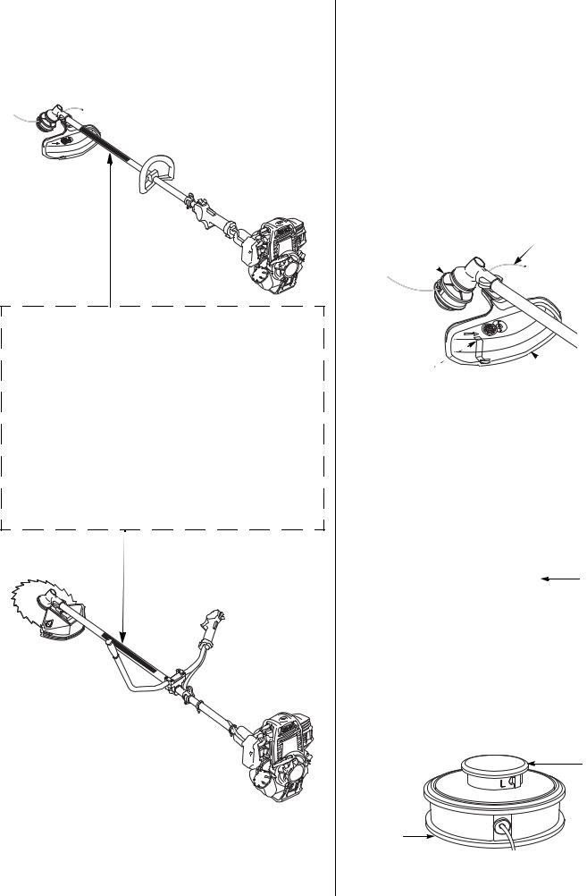
TYPE EQUIPPED WITH
LOOP HANDLE
TYPE EQUIPPED WITH
U-TYPE HANDLEBAR
RECOMMENDED CUTTING ATTACHMENTS
CUTTING-LINE HEADS AND SHIELDS
A cutting-line head containing nylon monofilament line and a debris shield with a cutoff knife is standard equipment. The shield’s cutoff knife automatically removes any excess line that is released from the cutting head.
The U-type handlebar trimmers are supplied with two different debris shields. Use the debris shield with the cutoff knife when the cutting-line head is installed.
Nylon monofilament line is suitable for cutting grass and ordinary weeds, but not brush and woody growth.
CUTTING-LINE HEAD |
NYLON MONOFILAMENT LINE |
CUTOFF KNIFE  DEBRIS SHIELD
(inside the debris shield)
Manual-Feed Cutting-Line Head
Line is released from the cutting head by manually pulling and turning the spool with the trimmer engine stopped.
To release more line, pull the spool and turn it counterclockwise.
SPOOL
HOUSING 
Semi-Matic (bump-feed) Cutting-Line Head
Line is released from the cutting head by bumping the spool on hard ground while the head is spinning. Do not tap the cutting-line head on pavement or concrete.
SPOOL
HOUSING
3
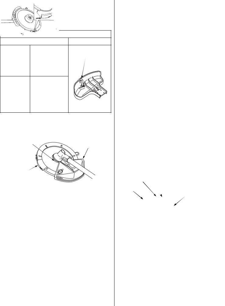
BLADES AND SHIELDS
A variety of blades are available from your Honda trimmer servicing dealer. Always use a debris shield designed for use with a blade when attaching a blade to your trimmer. The blade type debris shield does not have a cutoff knife.
DEBRIS SHIELDS
BLADE |
CUTTING-LINE |
GRASS/WEED |
CUTOFF KNIFE |
BLADE, WEED/ |
|
BRUSH BLADE |
|
(optional part) |
|
BRUSH/WOOD |
|
BLADE |
|
Honda U-type handlebar trimmers are supplied with a blade cover surrounding the edge of the blade. For safety, and to protect the blade, the cover should be installed whenever the trimmer is not in
use.
BLADE |
DEBRIS |
|
SHIELD |
BLADE
COVER
If installing a metal blade on a Honda trimmer equipped with a loop handle, also install the optional barrier kit that includes a full shoulder harness, a barrier bar, and a debris shield for metal blades. Follow the safety information and installation instructions that come with the kit.
Grass/Weed Blades
Grass/weed blades, which may be plastic or metal, are used as an alternative to nylon monofilament line for cutting grass and ordinary weeds.
However, blades should never be used for edging against solid surfaces.
4
Weed/Brush Blades
These metal blades have chisel-shaped teeth that are used for cutting through field grass, thick weeds, and light brush. They are not designed for sawing woody material. The teeth must be sharp for good results.
Brush/Wood Blades
These metal saw-tooth blades are used for sawing through saplings, shrubs and woody brush. The teeth must be sharp for good results. Brush/wood blades will also cut grass and weeds, but they are not efficient for that purpose.
Brush/Wood Blade Cover Installation and Removal
1.Install the blade cover over the blade so half the blade is covered.
To prevent the post end from interfering with the debris shield, pull the post end away from the blade and set it on top of the blade as shown.
Turn the blade cover slowly until the post end clears the debris shield.
2.Reposition the post end over the blade.
3.With the blade cover fully seated on the blade, latch the tab over the post.
Remove the blade cover in the reverse order of installation.
BLADE |
POST END |
|
DEBRIS
SHIELD
BLADE COVER

CUTTING ATTACHMENT APPLICATIONS
Type |
Line Size |
Blade Diameter |
|
|
|
HHT25S |
0.095 in |
9 in |
|
|
|
HHT35S |
0.095 or 0.105 in |
9 or 10 in |
|
|
|
ATTACHMENTS FOR TRIMMING GRASS AND LIGHT WEEDS
ATTACHMENTS FOR CUTTING THICK WEEDS AND LIGHT BRUSH
ATTACHMENTS FOR CUTTING WOODY BRUSH, SHRUBS, SAPLINGS
Your Honda trimmer servicing dealer has cutting attachments that have been designed and approved for your trimmer and are covered by warranty. Non-Honda attachments are usually designed for universal applications. Although aftermarket attachments may fit on your trimmer, they may not meet factory specifications and could make your trimmer unsafe.
ASSEMBLY
After assembly and before operation, review the SAFE OPERATING PRECAUTIONS on page 12.
IMPORTANCE OF PROPER ASSEMBLY
Proper assembly is essential to operator safety and the reliability of the machine. Any error or oversight made by the person assembling and servicing a machine can result in faulty operation, damage to the machine, or injury to the operator.
Some of the most important safety precautions are given below. However, we cannot warn you of every conceivable hazard that can arise in performing this assembly. Only you can decide whether or not you should perform a given task.
WARNING
Improper assembly can cause an unsafe condition that can lead to serious injury or death.
Follow the procedures and precautions in the assembly instructions carefully.
WARNING
Failure to properly follow instructions and precautions can cause you to be seriously hurt or killed.
Follow the procedures and precautions in this manual carefully.
IMPORTANT SAFETY PRECAUTIONS
•Make sure you have a clear understanding of all basic shop safety practices and that you are wearing appropriate clothing and safety equipment.
•Read the instructions before you begin and be sure you have the tools and skills required to perform the tasks safely.
•Make sure the engine is off before you begin any maintenance or repairs. This will help eliminate several potential hazards:
Carbon monoxide poisoning from engine exhaust. Be sure there is adequate ventilation whenever you run the engine.
Burns from hot parts. Let the engine and exhaust system cool before touching.
Injury from moving parts. Do not run the engine unless the instruction tells you to do so. Even then, keep your hands, fingers, and clothing away from moving parts. Do not run the engine when any protective guard or shield is removed.
•To reduce the possibility of a fire or explosion, be careful when working around gasoline or batteries. Use only a nonflammable solvent, not gasoline, to clean parts. Keep all cigarettes, sparks, and flames away from all fuel-related parts.
UNPACKING
Carefully remove the trimmer and loose parts from the carton and compare the loose parts with the inventory list on page 6.
Tools Required (U-type handlebar only):
A 4 mm hex wrench, 8 and 17 mm sockets, 0 to 25 ft-lb torque wrench.
5
LOOSE PARTS
Check all loose parts against the following list. Contact your authorized Honda servicing dealer if any of the loose parts shown are not included with your trimmer.
Ref. |
Description |
All |
Loop |
U-type |
Qty. |
|
No |
handle |
handlebar |
||||
|
|
|
||||
|
|
|
|
|
|
|
1 |
Owner’s Manual |
• |
|
|
1 |
|
|
|
|
|
|
|
|
2 |
Goggles |
• |
|
|
1 |
|
|
|
|
|
|
|
|
3 |
Oil bottle |
• |
|
|
1 |
|
|
|
|
|
|
|
|
4 |
Single-strap shoulder |
|
• |
|
1 |
|
harness |
|
|
||||
|
|
|
|
|
||
|
|
|
|
|
|
|
5 |
Full shoulder harness |
|
|
• |
1 |
|
|
|
|
|
|
|
|
|
Debris shield, for |
|
|
|
|
|
6 |
30 ~ 80 tooth saw |
|
|
• |
1 |
|
|
blades only |
|
|
|
|
7 |
|
Cover |
|
|
• |
1 |
8 |
|
Left-hand thread lock |
|
• |
1 |
|
|
nut, 10 mm |
|
||||
|
|
|
|
|
||
9 |
|
Saw blade, |
|
• |
1 |
|
|
50 tooth/10 in |
|
||||
|
|
|
|
|
||
10 |
Blade cover |
|
• |
1 |
||
|
|
1 |
2 |
3 |
4 |
|
|
|
|
|
|
|
|
INTRODUCTION |
|
|
|
|
|
|
|
|
OWNER’S MANUAL |
|
|
|
|
|
|
HHT25S • HHT35S |
|
|
|
|
|
|
Trimmer/Brush Cutter |
|
|
|
|
SAFETY MESSAGES |
WARNING: |
|
|
|
|
|
|
|
|
|
|
||
|
|
CONTENTS |
|
|
|
|
DANGER |
|
|
10W-30 |
|
|
|
|
|
Genuine Honda Oil |
|
|
||
|
WARNING |
|
|
blended for Honda engines. |
|
|
|
|
|
Specially formulated and |
|
|
|
CAUTION |
|
|
Meets or exceeds American |
|
|
|
|
|
Petroleum Institute SJ |
|
|
||
|
|
standards. |
|
|
||
|
|
|
|
100 cc / 3.4 oz |
|
|
U-Type Handlebar Only
5 |
6 |
7 |
8 |
10
9
6
U-TYPE HANDLEBAR
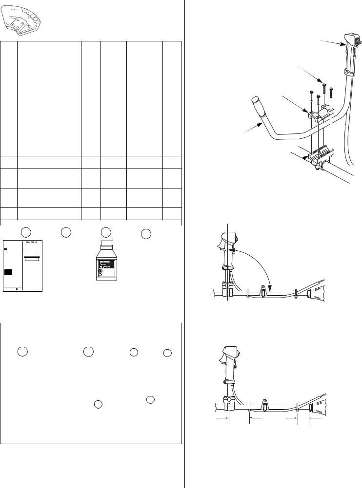
Installation
1. Remove the four 5 x 28 mm bolt/washers and handlebar holder A.
THROTTLE TRIGGER
5 x 28 mm BOLT/WASHER (4)
HANDLEBAR
HOLDER A
U-SHAPED
HANDLEBAR 
HANDLEBAR 
HOLDER B
2.Set the U-shaped handle into handlebar holder B with the throttle trigger facing to the right.
3.Adjust the handlebar position as shown.
90°
4.Tighten the four 5 x 28 mm bolt/washers.
TORQUE: 3.6 ft-lb (5 N·m)
5.Make sure the tie straps are positioned as shown.
3.9 in (100 mm) |
2.4 in (60 mm) |
6.Operate the throttle trigger and make sure the throttle operates smoothly.
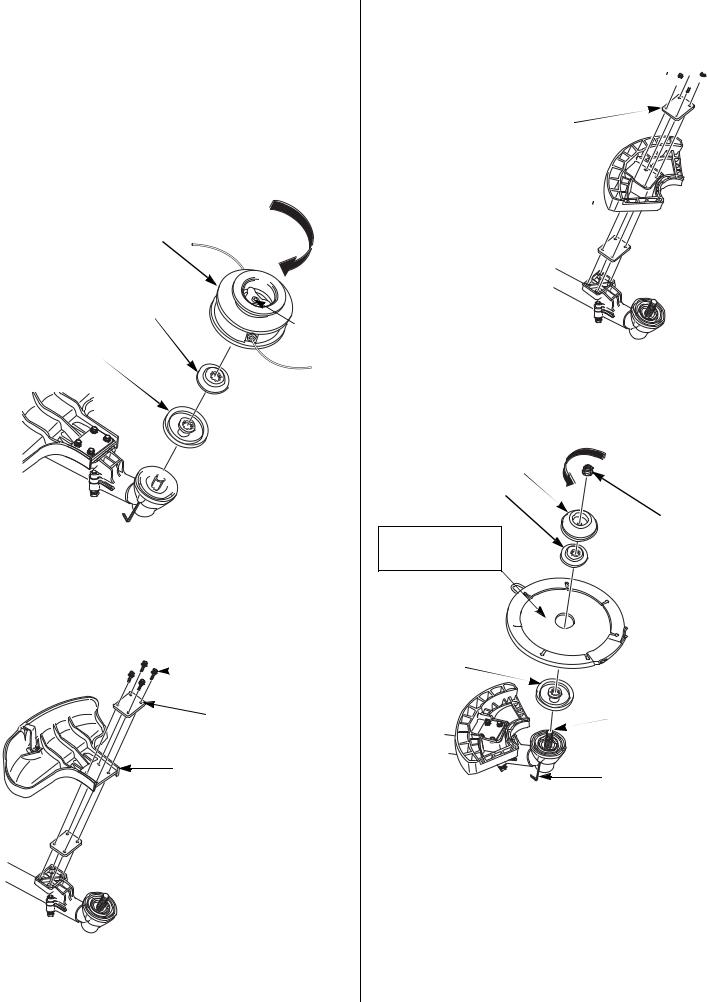
SAW BLADE
The U-type handlebar models are shipped with a manual nylon cutting-line head installed on the trimmer. If the saw blade is needed, move the ignition switch to the STOP (O) position and disconnect the spark plug cap from the spark plug. Wear protective gloves when working around the cutting-line head and saw blade.
Cutting-Line Head Removal
1.Align the gear case hole with the groove in cover plate/spacer A. Insert a 4 mm hex wrench or equivalent into the gear case hole to prevent the left-hand threaded output shaft from turning.
CUTTING-LINE HEAD
ASSEMBLY
SPACER B
|
KNOB |
COVER PLATE/ |
(Do Not |
Remove) |
|
SPACER A |
|
OUTPUT SHAFT

 (left-hand thread)
2.Hold the wrench and rotate the cutting-line head in the direction of the arrow and remove the cutting-line head assembly.
Remove the cutting-line head as an assembly. Do not remove the knob. Refer to page 20 for a cutting-line head assembly drawing.
Debris Shield Removal/Installation
1. Remove the cutting-line debris shield.
5 x 28 mm BOLT/WASHER (4)
SPACER (2)
[3/32" (2.3 mm) thick]
CUTTING-LINE DEBRIS SHIELD (with cutoff knife)
2. Install the brush/wood blade debris shield.
Tighten the bolt/washers:
TORQUE: 2.5 ft-lb (3.4 N·m)
5 x 28 mm 

 BOLT/WASHER (4)


SPACER (2) [3/32" (2.3 mm) thick]
BRUSH/WOOD BLADE 
DEBRIS SHIELD
Saw Blade Installation
1.Insert a 4 mm hex wrench or equivalent into the gear case hole to prevent the output shaft from turning.
2.Install cover plate/spacer A onto the output shaft as shown.
COVER 
SPACER B
BLADE
Install with the white markings facing the debris shield. 
BLADE 
 COVER
COVER 


COVER PLATE/
SPACER A
TIGHTEN
10 mm LOCK NUT (left-hand thread)
 OUTPUT SHAFT (left-hand thread)
4 mm HEX TOOL
3.With the blade cover installed on the blade, install the blade by aligning the center of the blade with the shoulder on cover plate/ spacer A.
4.Install spacer B, the cover, and the 10 mm lock nut as shown.
Be sure to install the blade with the cutting edges of the saw teeth in the direction of rotation; the side with the white markings must face the debris shield.
The output shaft has left-hand threads. Tighten the 10 mm lock nut counterclockwise.
TORQUE: 14 ft-lb (20 N•m)
5.Remove the 4 mm hex wrench or equivalent from the gear case.
7

Blade Cover Removal
1.Turn the blade cover slowly until the cover latch is clear of the debris shield.
Unfasten the latch by lifting the tab off the post.
 POST
POST
 TAB
TAB
 BLADE COVER
2.Pull the post end away from the blade and set it on top of the blade as shown.
POST END
3.Turn the blade cover slowly until the post end is clear of the debris shield, then remove the blade cover from the blade.
 POST END
Blade Cover Installation
1.Install the blade cover over the blade so half of the blade is covered.
To prevent the post end from interfering with the debris shield, pull the post end away from the blade and set it on top of the blade as shown above.
2.Turn the blade cover slowly until the post end clears the debris shield.
3.Reposition the post end over the blade.
4.With the blade cover fully seated on the blade, latch the tab over the post.
8
ENGINE OIL
The trimmer is shipped WITHOUT OIL in the engine.
1.Place the trimmer on a level surface then remove the oil filler cap/dipstick.
OIL FILLER OPENING
OIL FILLER CAP/DIPSTICK
2.Slowly add the recommended oil (included in the box) to the bottom edge of the oil filler opening. Do not overfill, as the engine oil tank capacity is small.
3.If the supplied oil is not used, add enough SAE 10W-30 API service category SJ or later oil. Add oil until the oil level is to the bottom edge of the oil filler opening.
NOTICE
Running the engine with too little or too much oil can cause engine damage.
4. Screw in the oil filler cap/dipstick securely.
FUEL
See page 24.
BEFORE USING YOUR TRIMMER
On blade equipped models, always remove the blade cover before starting the engine. If the cover is not removed, the blade cover may fly off at high speed during test operation. Reinstall the blade cover when the trimmer is not being used.
Before using the trimmer, all trimmer operators must read the following sections.
•TRIMMER SAFETY (page 2)
•CONTROLS & EQUIPMENT (page 9)
•BEFORE OPERATION (page 11)
•OPERATION (page 12)
•MAINTENANCE SCHEDULE (page 17)

CONTROLS AND EQUIPMENT
COMPONENT CONTROLS AND LOCATIONS
Loop Type Handle
CUTTING-LINE HEAD
GEAR CASE |
|
LOOP HANDLE |
HARNESS HANGER |
|
|
|
THROTTLE SET BUTTON |
DEBRIS SHIELD |
OPERATOR |
PRESENCE |
|
WITH CUTOFF KNIFE |
LEVER |
DRIVE CABLE
FRAME PIPE
IGNITION SWITCH
THROTTLE
TRIGGER
U-Type Handlebar
This type is supplied with a cutting-line head, a saw blade, and two debris shields.
SAW BLADE |
|
IGNITION SWITCH |
|
GEAR CASE |
THROTTLE |
|
|
|
TRIGGER |
THROTTLE |
|
DRIVE CABLE |
|||
SET BUTTON |
|||
FRAME PIPE |
|||
|
|||
|
|
OPERATOR |
|
|
|
PRESENCE |
|
|
|
LEVER |
|
DEBRIS SHIELD |
|
HARNESS |
|
FOR BRUSH/ |
|
HANGER |
|
WOOD BLADE |
|
|
|
U-TYPE
HANDLEBAR
CUTTING-LINE HEAD
 DEBRIS SHIELD WITH
CUTTING KNIFE
Engine
|
SPARK PLUG |
|
|
CHOKE |
|
|
LEVER |
|
|
SPARK |
|
|
ARRESTER |
|
AIR |
|
|
CLEANER |
|
|
COVER |
|
|
PRIMING |
STARTER |
|
GRIP |
||
BULB |
||
|
||
FUEL RETURN |
|
|
TUBE (CLEAR) |
OIL FILLER CAP |
FUEL SUPPLY
TUBE (BLACK)
FUEL TANK CAP
CONTROLS
The location and operation of the controls are similar on both the HHT25S and HHT35S models.
Choke Lever
The choke lever opens and closes the choke valve.
The CLOSED position enriches the fuel mixture for starting a cold engine.
The OPEN position provides the correct fuel mixture for operation after starting, and for restarting a warm engine.
CHOKE LEVER
CLOSED
OPEN
9

Ignition Switch
The ignition switch controls the ignition system.
The ignition switch must be in the ON (I) position for the engine to start and run.
Moving the ignition switch to the STOP (O) position stops the engine.
U-type Handle: |
Loop Handle: |
STOP |
STOP (O) |
(O) |
ON (I) |
|
|
|
OPERATOR |
|
PRESENCE |
ON (I) |
LEVER |
|
IGNITION
SWITCH
IGNITION
SWITCH
OPERATOR
PRESENCE
LEVER
Operator Presence Lever
The operator presence lever blocks the throttle trigger. This safety feature prevents unintentional throttle operation if the trimmer is bumped while the operator’s hand is not on the control handle.
When the operator presses the presence lever by gripping the control handle, the trigger moves freely.
Throttle Trigger
The throttle trigger controls engine speed.
Pulling the throttle trigger toward the control handle grip increases engine speed. The trimmer will have the greatest cutting force at maximum engine speed.
Releasing the throttle trigger reduces engine speed. At idle, the cutting attachment should coast to a stop.
THROTTLE TRIGGER
IDLE  (cutting attachment stops) THROTTLE
SET BUTTON
FAST (cutting attachment rotates)
Throttle Set Button
The throttle set button is used to hold the throttle trigger at the fast idle position for starting. Do not allow the cutting line or blade to contact any obstruction when starting the engine with the throttle set button engaged.
To engage the throttle set button, press the operator presence lever by gripping the control handle, pull the throttle trigger, then press and hold the throttle set button while releasing the throttle trigger.
To disengage the throttle set button, simply pull the throttle trigger. The throttle set button automatically disengages when the throttle trigger is pulled.
Do not use the throttle set button while operating the trimmer. The trimmer will not return to idle, and the cutting-line head or blade will continue to spin until the throttle set button is disengaged and the throttle trigger is released.
10
Priming Bulb
Pressing the priming bulb pumps fuel from the fuel tank to the carburetor. This procedure is necessary for starting the engine.
To ensure fuel has reached the carburetor, press the priming bulb repeatedly until fuel can be seen in the clear plastic fuel return tube.
PRIMING
BULB
FUEL RETURN TUBE (clear plastic tube)
RECOIL STARTER GRIP
Recoil Starter Grip
Pulling the starter grip operates the recoil starter to turn the engine for starting.
EQUIPMENT
The Honda HHT25S and HHT35S trimmer/brush cutters are supplied with a shoulder harness and safety glasses. Refer to page 11 for a description of other equipment and protective clothing you will need.
Shoulder Harness
A full shoulder harness must be worn by the operator of these Honda trimmers/brush cutters when equipped with a blade and debris shield. If the trimmer is equipped with a cutting-line head and shield with cutoff knife, the operator may wear a single-strap harness.
A suitable shoulder harness is supplied with each new Honda HHT25S and HHT35S trimmer/brush cutter. Replacement shoulder harnesses may be purchased through any authorized Honda trimmer/brush cutter servicing dealer.
Before operation, adjust your shoulder harness as described on page 12.
SINGLE-STRAP SHOULDER HARNESS (Loop type handle)
QUICK-RELEASE LATCH
FULL SHOULDER HARNESS (U-type handlebar)
QUICK-RELEASE LATCH
Loading...