


LCD Monitor
User Manual
UD.6L0203D1207A02
0

LCD Monitor User Manual
About this Manual
This Manual is applicable to LCD Monitor (V1.4).
The Manual includes instructions for using and managing the product. Pictures, charts, images and all other
information hereinafter are for description and explanation only. The information contained in the Manual is subject
to change, without notice, due to firmware updates or other reasons. Please find the latest version in the company
website
Please use this user manual under the guidance of professionals.
Legal Disclaimer
REGARDING TO THE PRODUCT WITH INTERNET ACCESS, THE USE OF PRODUCT SHALL BE
WHOLLY AT YOUR OWN RISKS. OUR COMPANY SHALL NOT TAKE ANY RESPONSIBILITES FOR
ABNORMAL OPERATION, PRIVACY LEAKAGE OR OTHER DAMAGES RESULTING FROM CYBER
ATTACK, HACKER ATTACK, VIRUS INSPECTION, OR OTHER INTERNET SECURITY RISKS; HOWEVER,
OUR COMPANY WILL PROVIDE TIMELY TECHNICAL SUPPORT IF REQUIRED.
SURVEILLANCE LAWS VARY BY JURISDICTION. PLEASE CHECK ALL RELEVANT LAWS IN YOUR
JURISDICTION BEFORE USING THIS PRODUCT IN ORDER TO ENSURE THAT YOUR USE CONFORMS
THE APPLICABLE LAW. OUR COMPANY SHALL NOT BE LIABLE IN THE EVENT THAT THIS
PRODUCT IS USED WITH ILLEGITIMATE PURPOSES.
IN THE EVENT OF ANY CONFLICTS BETWEEN THIS MANUAL AND THE APPLICABLE LAW, THE
LATER PREVAILS.
1

LCD Monitor User Manual
Regulatory Information
FCC Information
FCC compliance: This equipment has been tested and found to comply with the limits for a Class A digital device,
pursuant to part 15 of the FCC Rules. These limits are designed to provide reasonable protection against harmful
interference when the equipment is operated in a commercial environment. This equipment generates, uses, and can
radiate radio frequency energy and, if not installed and used in accordance with the instruction manual, may cause
harmful interference to radio communications. Operation of this equipment in a residential area is likely to cause
harmful interference in which case the user will be required to correct the interference at his own expense.
FCC Conditions
This device complies with part 15 of the FCC Rules. Operation is subject to the following two conditions:
1. This device may not cause harmful interference.
2. This device must accept any interference received, including interference that may cause undesired operation.
EU Conformity Statement
This product and - if applicable - the supplied accessories too are marked with "CE" and comply
therefore with the applicable harmonized European standards listed under the EMC Directive
2004/108/EC, the RoHS Directive 2011/65/EU.
2012/19/EU (WEEE directive): Products marked with this symbol cannot be disposed of as unsorted
municipal waste in the European Union. For proper recycling, return this product to your local supplier
upon the purchase of equivalent new equipment, or dispose of it at designated collection points. For
more information see: www.recyclethis.info
2006/66/EC (battery directive): This product contains a battery that cannot be disposed of as unsorted
municipal waste in the European Union. See the product documentation for specific battery information.
The battery is marked with this symbol, which may include lettering to indicate cadmium (Cd), lead
(Pb), or mercury (Hg). For proper recycling, return the battery to your supplier or to a designated collection point.
For more information see: www.recyclethis.info
2

Table of Contents
Safety Precaution ................................................................................................................................6 Chapter 1
1.1 Cleaning the Device ................................................................................................................................. 6
Installation and Connection ...............................................................................................................7 Chapter 2
2.1 Installation Precaution ............................................................................................................................. 7
2.2 Interface Description................................................................................................................................ 7
2.3 Power Connection .................................................................................................................................... 9
2.4 System Connection .................................................................................................................................. 9
Controlling the LCD Monitor .......................................................................................................... 11 Chapter 3
3.1 Installing and Uninstalling the Screen Control Client Software ............................................................. 11
3.2 Running the Client Software .................................................................................................................. 12
3.2.1 Running the Client software ...................................................................................................... 12
3.2.2 Video Wall Layout ..................................................................................................................... 13
3.3 GUI Introduction ................................................................................................................................... 14
3.4 Control and Management ....................................................................................................................... 14
3.4.1 Scene Management .................................................................................................................... 14
3.4.2 Remote Control .......................................................................................................................... 16
3.4.3 Turn on/Turn off the Screen ....................................................................................................... 17
3.4.4 Signal Source Switch ................................................................................................................. 18
3.4.5 Enable/Disable Region Zoom .................................................................................................... 19
3.4.6 Screen Status .............................................................................................................................. 19
3.4.7 Window Spanning Settings ........................................................................................................ 21
3.4.8 Image Parameters Configuration ............................................................................................... 22
3.5 System Configuration ............................................................................................................................ 24
3.5.1 Communication Settings ............................................................................................................ 24
3.5.2 Matrix Settings ........................................................................................................................... 25
3.5.3 Matrix Output Settings ............................................................................................................... 27
3.5.4 Screen ID Settings ..................................................................................................................... 28
3.6 Advanced Settings ................................................................................................................................. 29
3.6.1 Fan Settings................................................................................................................................ 29
3.6.2 Maintenance ............................................................................................................................... 30
3.6.3 Edge Blanking............................................................................................................................ 31
3.6.4 Time Settings ............................................................................................................................. 32
3.6.5 Others ......................................................................................................................................... 34
Appendix ............................................................................................................................................36 Chapter 4
4.1 Specifications ......................................................................................................................................... 36
4.2 Trouble Shootings .................................................................................................................................. 45
3

LCD Monitor User Manual
Warnings Follow these safeguards to prevent
serious injury or death.
Cautions Follow these precautions to prevent
potential injury or material damage.
Safety Instruction
These instructions are intended to ensure that user can use the product correctly to avoid danger or property loss.
The precaution measure is divided into “Warnings” and “Cautions”.
Warnings: Serious injury or death may occur if any of the warnings are neglected.
Cautions: Injury or equipment damage may occur if any of the cautions are neglected.
Warnings
In the use of the product, you must be in strict compliance with the electrical safety regulations of the nation
and region.
Please refer to technical specifications for detailed information.
Do not connect several devices to one power adapter as adapter overload may cause over-heating or a fire
hazard.
Please make sure that the plug is firmly connected to the power socket.
If smoke, odor or noise rise from the device, turn off the power at once and unplug the power cable, and then
please contact the service center.
If the product does not work properly, please contact your dealer or the nearest service center. Never attempt to
disassemble the device yourself. (We shall not assume any responsibility for problems caused by unauthorized
repair or maintenance.)
Cautions
Make sure the power supply voltage is correct before using the device.
Do not drop the device or subject it to physical shock.
Make sure the AC outlet is unplugged or switched to OFF before the repair or maintenance in case of the
human injury.
Do not aim the device at the sun or extra bright places. Blooming or smearing may occur otherwise (which is
not a malfunction), and affect the endurance of screen at the same time.
When the product is mounted on wall or ceiling, the device shall be firmly fixed.
Do not bend, pull or drag the power cord, and do not change the position of the power cord randomly. Make
sure the power cord is away from the heat resource in case of the fire or electric shock. Please contact the
dealer if there is anything wrong with the power cord.
The screen may be burned out by a laser beam, so when any laser equipment is in using, make sure that the
surface of screen will not be exposed to the laser beam.
To avoid heat accumulation, good ventilation is required for operating environment.
Keep the device away from liquid while in use.
While in delivery, the device shall be packed in its original packing, or packing of the same texture.
Improper use or replacement of the battery may result in hazard of explosion. Replace with the same or
4

LCD Monitor User Manual
equivalent type only. Dispose of used batteries according to the instructions provided by the battery
manufacturer.
Some mechanical or electrical components possesses of the special safety protection function. Those protection
functions may be ignored by unwariness during the safety exam. However, the special safety function (high
rated voltage or rated power, etc.) cannot be gained on the replaced components. All those original electrical
components with the special safety function are listed on the international dangerous symbols. And the
electrical components replaced the originals may cause electric shock, fire or other potential danger.
5

LCD Monitor User Manual
Safety Precaution Chapter 1
Any repair or maintenance should be done by the professional technicians who are quite familiar with the safety
precaution measures. Please follow the safety precautions below during the repair or maintenance.
The LCD monitor is fragile, please handle it with care. Do not crush on the screen with hands or other things.
Never rub or tap the device with hard objects. Make sure the device faces upward in case of the screen crush.
Our company bears no responsibility for damage caused by the customer.
Clean the rear panel and screen before installation.
Do not display static images on the screen, otherwise they will remain "residual image" on the screen and affect
the general use of the LCD monitor.
Make sure all the components are correctly installed, and no objects left in the box after the repair or
maintenance.
Do not turn on/off the video wall frequently, and the duration between the ON and OFF should be longer than 3
minutes.
Do not place the device in extremely hot, cold (the operating temperature shall be (0º C to 40º C), dusty or
damp locations, and do not expose it to high electromagnetic radiation.
Please make sure that the device in the package is in good condition and all the assembly parts are included.
Do not drop the device or subject it to physical shock. Do not place the LCD monitor on an unstable objects or
unsafe area.
To avoid heat accumulation or it may cause the device to be overheating.
Do not use the LCD monitor in a dusty, high humidity, oily or humid environment, it may cause a fire or
damage to the device.
Do not over tighten when install the screen.
1.1 Cleaning the Device
Use the non-dust cloth to wipe the frame and screen after the power is switched off. Do not wipe the screen with
the harsh stuff or touch the screen directly with your hands and the chemical cleanser is not allowed, either.
Dedicated non-dust cloth is provided to clean the frame and the screen. You can moisten the cloth with water or
absolute ethyl alcohol, or you can also use the dry compressed air (oil-free) to blow the dust on the screen.
Do not use the cotton or hemp-free paper moisten with the organic solvent or volatile solvent, such as alcohol
(except for absolute ethyl alcohol), gasoline, banana oil, washer fluid, or liquid detergent, etc., which will
cause the protective layer spalling or ageing. The rubber or the plastic materials fall on the screen surface for a
long time will turns to a stain which will affect the image quality.
6

LCD Monitor User Manual
Interface
Description
Interface
Description
Power
Connecting the power cable
VIDEO OUT 1
CVBS Analog Signal
Loop Video Output1
HDMI IN
HDMI Digital Signal Input
VIDEO OUT 2
CVBS Analog Signal
Loop Video Output2
Installation and Connection Chapter 2
2.1 Installation Precaution
Make sure that all the related equipment is power-off during the installation.
Check the specification of the products for the installation environment.
Make sure the installation surface is strong enough to withstand four times the weight of the device and the
mounting.
The non-professionals are not recommended to do the installation.
Do not block the vents. It may cause a device exception if the internal temperature of LCD monitor rises.
Use the mounting base and wall-mounting bracket which were specially designed for the LCD monitor.
Do not grasp the screen for moving the LCD monitor. It may cause a damage of the product.
The LCD monitor should be mounted vertically. If necessary, keep the gradient between 0° to 20°.
2.2 Interface Description
The main interfaces of different models are shown below:
DS-D2046NL-B/DS-D2046NH-B/DS-D2055NL/DS-D2055NH
Figure 2. 1 Real Panel Interface (1)
DS-D2046NH-C/DS-D2046NL-C/DS-D2055NH-B/DS-D2055NL-B
Figure 2. 2 Real Panel Interface (2)
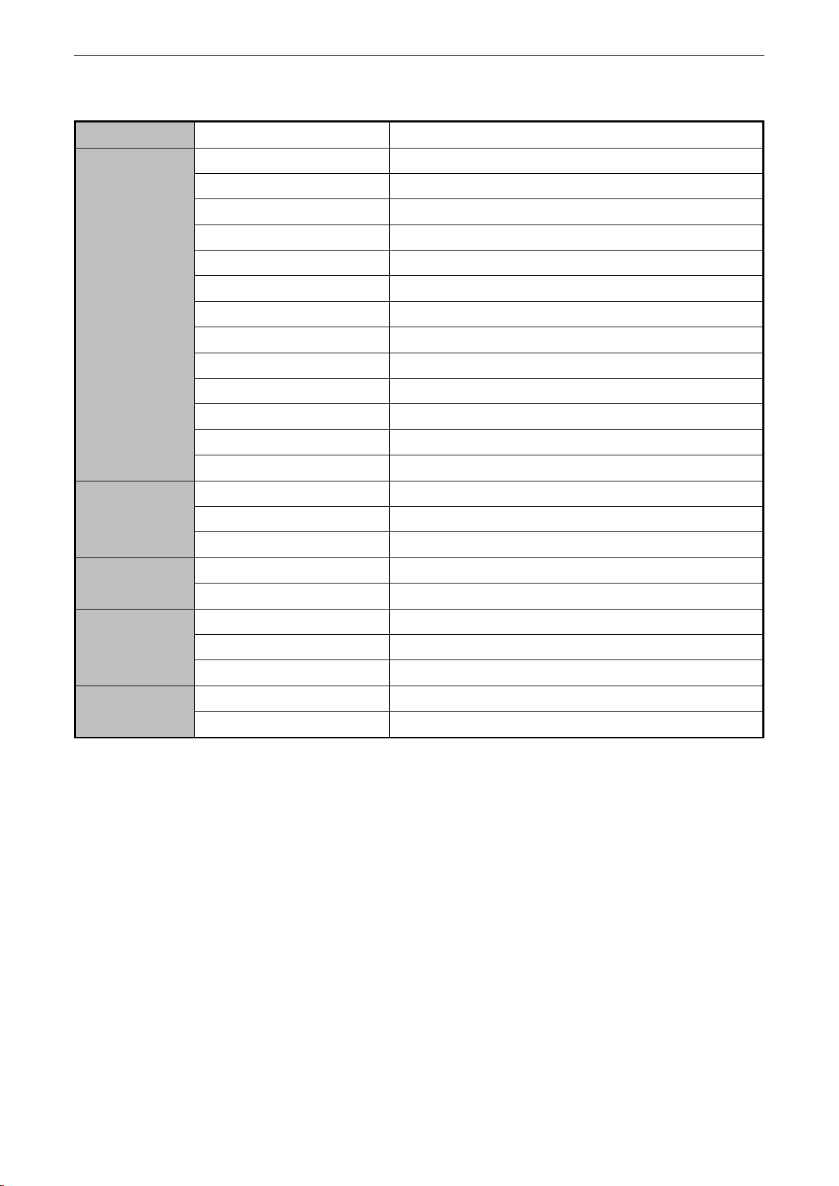
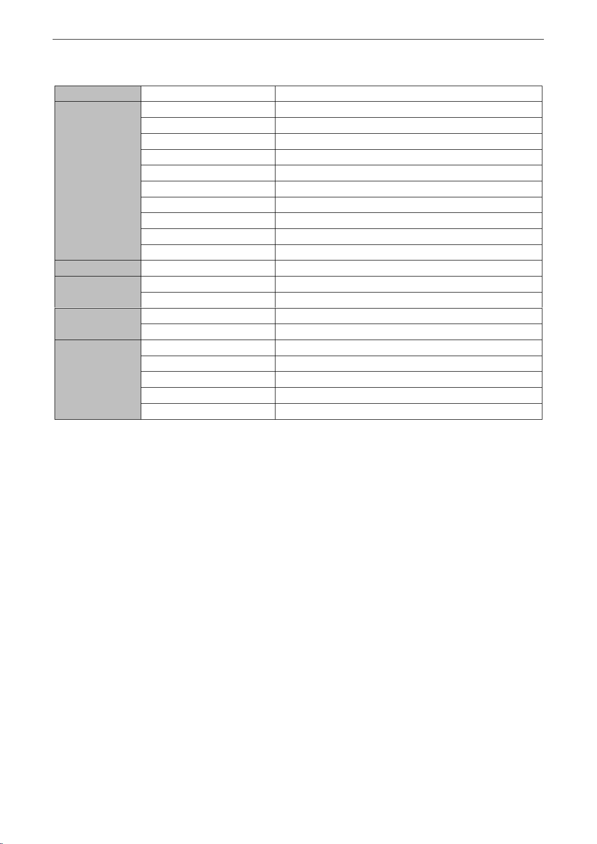
Table 2. 1 Interface Description
7

LCD Monitor User Manual
Interface
Description
Interface
Description
Power
Connecting the power cable
VIDEO IN
CVBS Analog Signal
Input
DVI IN
DVI Digital Signal Input
RS232 IN
Serial Port Input
VGA IN
VGA Analog Signal Input
RS232 OUT
Serial Port Output
Y/IN
Y Component Signal Input
IR IN
IR Input Interface
Pr/IN
Pr Component Signal Input
USB
USB Interface
Pb/IN
Pb Component Signal Input
POWER
Power Indicator
DVI IN
DVI Digital Signal Input
RS232 IN
Serial Port Input
DVI OUT
DVI Digital Signal Loop Video
Output
RS232 OUT 1
Serial Port Loop Video
Output1
VGA IN
VGA Analog Signal Input
RS232 OUT 2
Serial Port Loop Video
Output2
VGA OUT
VGA Analog Signal Loop Video
Output
USB
USB Interface
Y/IN
Y Component Signal Input
ADDRESS ID
Dial Switch
Pb/IN
Pb Component Signal Input
IR IN
IR Input Interface
Pr/IN
Pr Component Signal Input
POWER
Power Indicator
VIDEO IN
CVBS Analog Signal Input
DS-D2046NL-B/Z/DS-D2046NH-B/Z/DS-D2055NL-Y
Figure 2. 3 Real Panel Interface (3)
Table 2. 2 Interface Description
The video may not be displayed properly because of the unmatched video card of the PC.
The analog signal channel may not be able to properly display an image with a resolution of 1920 × 1080. In
this case, check your PC (video card) settings to verify whether the input signal can be matched with the
specification of the LCD monitor.
Use DVI, VGA and BNC cables for signal input.
Use BNC cable for YPbPr signal Input.
Use BNC cable for composite video connector.
The PWR indicator shows the different working statuses of the screen with different colors. Green indicates
properly working. Red denotes standby. Orange denotes the fan exception of the screen.
8

LCD Monitor User Manual
2.3 Power Connection
Plug the female end of the power cable to the power interface on the rear panel of the LCD monitor. Plug the other
end of the cable to a power outlet (220 V AC, 50/60Hz) with a good grounding capability.
Power Specification:100 to 240 V AC, 50/60Hz.
Turn off the main power switch of the monitor, and pull the plug from the power outlet if the LCD monitor is
used for a long time.
Never connect the device to a DC power
Figure 2. 4 Power Interface
2.4 System Connection
Correct connection method helps you to better control and properly display the video on the video wall.
A video wall with 2 × 2 layout mode is taken as an example to describe the connection as follows.
Figure 2. 5 Video Wall Layout
The system connection is divided into two phases: the control signal connections and the video signal connections.
The Control Signal Connection
The cables need to be connected ordinally in accordance with the order of the screen numbers. The screen numbers
are generally sorted row-by-row or column-by-column.
And you have to set the virtual and physical screen linkage in the Link Screen interface. See Chapter 3.5.4
Follow the wiring method shown in the figure below to compelete the connnection.
9

LCD Monitor User Manual
Figure 2. 6 Wiring Method
The Video Signal Connection
The monitor achieves the video signal from the signal loop video input port (for example, the DVI-IN), and send
the signal to the next unit through the signal loop video output port.
Follow the wiring method shown in the figure below to compelete the connnection.
Figure 2. 7 Video Signal Connection
The length of the cable as well as the environment condition may impact the image quality.
The DVI-IN interface is suggested to be used as the signal input port.
When operating on the cable connections, you must turn off the main power switch and pull out the power
plug.
Do not confuse the input and output interface, or it may cause the device exceptions or other problems.
10

LCD Monitor User Manual
Purpose:
To control the screen, you must install the screen control client software and run the server on your PC.
Steps:
1. Double click the setup program to enter the client software’s Install Shield Wizard. Follow the steps and
complete the installation.
Figure 3. 1 Install Shield Wizard
2. Run the application program again, and you can enter the updating interface of the program.
3. Or you can enter the Start menu, and select All Programs > Screen Control > Uninstall Screen Control to
uninstall the program.
Figure 3. 2 Uninstall the Software
Controlling the LCD Monitor Chapter 3
3.1 Installing and Uninstalling the Screen Control
Client Software
11

LCD Monitor User Manual
3.2 Running the Client Software
Follow the steps to access the software.
3.2.1 Running the Client software
Steps:
1. Click the icon to run the software after the installation is completed.
2. Choose the User Name with admin and guest available, input the the password, select the corresponding screen
type and cotrol mode with only serial available.
Figure 3. 3 Login Interface
The admin’s default password is 12345 which cannot be changed.
The LCD-D20 is the default screen type. Apart from default screen type, many screen types are available like
LCD-D20/SDI, LCD-D20/DP, LCD-D20-TVI, LCD-D20-Hdbase and LCD-D20.
LCD-D20/SDI includes VGA, HDMI, DVI, YPBPR, BNC and SDI signal sources.
LCD-D20/DP includes VGA, HDMI, DVI ,YPBPR , BNC and DP signal sources.
LCD-D20-TVI includes VGA, HDMI, DVI, YPBPR, BNC, and TVI signal sources.
LCD-D20-Hdbase includes VGA, HDMI, DVI, YPBPR, BNC and Hdbase signal sources.
LCD-D20 includes VGA, HDMI, DVI, YPBPR, and BNC signal sources.
3. Click Login to enter the client.
12

LCD Monitor User Manual
Click to enter the Screen Control page. Follow the steps shown below, and you can set the
video wall mode in this section.
Steps
1. On the Screen Control page, click in the upper-right side to pop up the Split Screen interface to input
the required row and column number (ranges from 1 to 15) into the corresponding textbox to set the split
screen mode.
Figure 3. 5 Split Screen Box
2. Click OK to complete the settings. The screen layout is displayed on the Screen Control page.
Figure 3. 4 Screen Control Interface
3.2.2 Video Wall Layout
Purpose:
13

LCD Monitor User Manual
Area
Name
Description
1
Menu Bar
Screen Control, System Configuration and Advanced Settings
2
Control Area
Scene, Matrix Management and Remote Control
3
Display Area
Show Monitor
4
Tool Bar
Signal Source Switch, Span/Split Screen, Image Parameters,
and Turn on/off the Screen
The Scene management enables you to save the video wall layout configuration and show it by clicking on the
scene name.
3. Slide the to zoom in and zoom out the virtual screen.
3.3 GUI Introduction
The GUI is shown below:
Figure 3. 6 Screen Control Interface
Table 3. 1 GUI Description
3.4 Control and Management
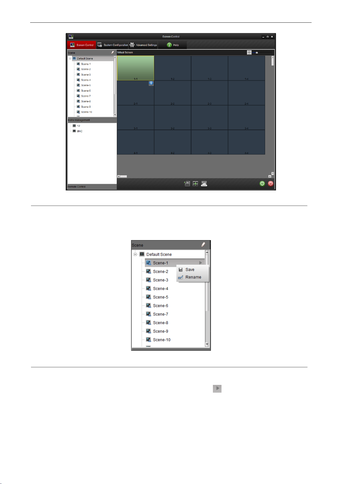
3.4.1 Scene Management
Purpose:
14
LCD Monitor User Manual
Figure 3. 7 Screen Control Interface
Save the Scene
After you set the screen and the matrix, right click a scene from the scene list, and select Save to save current
scene.
Figure 3. 8 Scene List
Display the Scene
Select a scene from the scene list on the left side of the page. Click to display the scene on the virtual
screen.
15

LCD Monitor User Manual
Figure 3. 9 Display the Scene
Rename the Scene
Select and right click a scene from the scene list. Select Rename to rename the scene.
Figure 3. 10 Edit Scene Name
Up to 16 scenes can be configured.
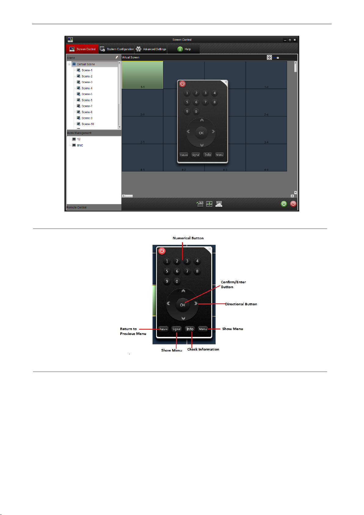
The remote control in the software allows you to remotely control the screen with this client software. The function
of this remote control is similar to the real one.
Steps:
1. Click Remote Control on the lower side of the left panel to display the virtual remote control.
Figure 3. 11 Tool Bar
2. You can drag the remote control to anywhere on the Screen Control page. Click the icon on the
upper-right corner of the remote control to close it.
3.4.2 Remote Control
Purpose:
16
LCD Monitor User Manual
Figure 3. 12 Remote Control Interface
Figure 3. 13 Remote Control Description
After the serial port configuration is completed, you can remotely turn on/turn off the screen through the software.
Steps:
1. Select a virtual screen and its background color turns green.
2. Right click the selected virtual screen and select to Turn on/off the screen.
3.4.3 Turn on/Turn off the Screen
Purpose:
17

LCD Monitor User Manual
Figure 3. 14 Turn on/off the Screen
3. You can click the button on the lower-right side of the page to control the screen.
4. You can also click on the remote control to close the window.
Figure 3. 15 Remote Control Interface
1. Select a screen to control.
2. Right click and select Switch Signal to list the signal sources. Select a signal source for the screen.
3. You can also click the icon on the lower-middle side of the page to choose a signal source for the screen.
Figure 3. 16 Signal Source Switch
3.4.4 Signal Source Switch
Steps:
18

LCD Monitor User Manual
3.4.5 Enable/Disable Area Zoom
Steps:
1. Select a screen to control.
2. Right click and select Enable Area Zoom , then the cursor changes to
3. Drag the from the lower left corner to the upper right corner to zoom in the screen which can be zoom in
for multiple times with the same operation. Drag the from the reverse direction to restore the screen to the
original size.
Figure 3. 17 Enable Region Zoom
4. Right click and select Disable Area Zoom and the changes to cursor again.
Figure 3. 18 Disable Region Zoom
3.4.6 Screen Status
1. Move the cursor to a screen, and the icon appears in the upper-right corner
19

LCD Monitor User Manual
2. Move the cursor to icon, and the Screen Status pops up.
Figure 3. 19 Screen Status (1)
Software Version
Software Version includes the version information.
Screen ID
Screen ID displays the screen’s ID number.
Working Time
Working Time records the working hours.
Temperature
Temperature displays the current screen temperature.
Temperature Status
Temperature Status includes Normal and Abnormal.
Fan
Fan includes On and Off
Fan Exception
Fan Exception includes Normal and Abnormal.
When the screen is unconnected the following screen status shows up.
20

LCD Monitor User Manual
Span the Screen
Steps:
1. Click and drag screens which need to be spanned.
2. Click the icon to make these screens to be spanned into one and to display the video from one signal
source. You are recommended to connect the same video source for the screens to be spanned, so that the
image of the video can be displayed properly on the spanned screen.
Figure 3. 21 The Spanned Screen
Figure 3. 20 Screen Status (2)
3.4.7 Window Spanning Settings
Purpose:
Several windows can be spanned in to one window with the same signal source, and the spanned window can also
be split into several windows.
21

LCD Monitor User Manual
Split the Screen
Steps:
1. Select the spanned screen
2. Split the spanned screen by clicking the icon again.
Figure 3. 22 The Split Screen
3.4.8 Image Parameters Configuration
Purpose:
In image parameters configuration interface image can be set in different ways.
Steps:
1. Select the screen which needs to be controlled.
2. Click the icon to enter the image parameters configuration page. You can modify basic image parameters
such as brightness, sharpness, contrast, color and hue on this page.
22

LCD Monitor User Manual
Figure 3. 23 Image Parameters Configuration
Sun mode is a set of parameters which you can choose to change the image parameters on the video wall.
Figure 3. 24 Sun Mode
The software presets four image modes to make the configuration to be easier. You can set the image mode as
normal, dynamic, soft and custom.
Figure 3. 25 Image Mode
If the mode is selected as Normal, Dynamic or Soft, the system configures the image parameters automatically
according to the requirement. If all the three modes cannot make you satisfied, you can select Custom as the image
mode, and to configure the image parameters manually.
The image parameters configuration requirements might be different for different signal sources. Therefore, the
non- professionals are not recommended to do such configuration.
23

LCD Monitor User Manual
The basic image parameters such as brightness, contrast, phase, clock horizontal position and vertical position are
adjustable for the VGA input.
The Backlight option on the Other Parameters panel can be used to adjust the brightness of the backlight of the
image.
You can adjust the image position by click the VGA Auto Adjust button on the lower side of the page.
The communication settings are necessary before you start to control the video wall.
Steps:
1. Click Serial Port Settings to enter the communication settings page. Select the serial port, corresponding
baud rate and check the check box of Enable Serial Port When Startup.
2. Click Set to save the settings.
For VGA Input
For Other Signal Source
The basic image parameters such as brightness, contrast, sharpness and color hue are adjustable for other signal
sources.
The Backlight option on the Other Parameters panel can be used to adjust the brightness of the backlight of the
image.
3. Click Advanced Settings to adjust color temperature and ADC adjustment where RGB gain and offset can be
set.
Figure 3. 26 Advanced Settings
Non-professionals are not recommended to perform advanced settings.
3.5 System Configuration
The system configuration page allows you to set communication settings, matrix related parameters settings and
screen ID settings.
Click System Configuration to enter the system configuration page.
3.5.1 Serial Port Settings
Purpose:
24

Figure 3. 27 System Configuration Interface
You may unable to control the screen if the communication settings are incorrect.
3.5.2 Matrix Settings
1. Add a Matrix
1) Click icon on the Matrix List panel to open the Add Matrix window.
2) Input a matrix name, and click OK to complete the settings.
Figure 3. 28 Add Matrix
2. Select a matrix in the list, and click the icon to rename the matrix. You can also delete this matrix by
clicking the icon .
LCD Monitor User Manual
Purpose:
Click Matrix Settings to enter the matrix settings page. The matrix related parameters are configurable on this
page. You can add matrixes and modify the matrix parameters by the following steps below.
Steps:
25

LCD Monitor User Manual
Figure 3. 29 Matrix List
3. Matrix Parameters Configuration
You can modify the matrix parameters on the Matrix Parameters panel.
Steps:
1) Select a loop mode for the matrix. If the mode is selected as YES, the control signal is transmitted to the
matrix through the monitor.
2) Set the Serial Port mode as Open to enable the connection.
3) Select the appropriate serial port number, baud rate, data bit, stop bit and parity.
4) Select a matrix type and a protocol for the matrix, and enter input/output number into the corresponding
textbox.
5) Click Save to save the settings.
Figure 3. 30 Matrix Settings
4. Custom Matrix
Purpose:
When using the third-party matrix, you should choose custom matrix to perform the corresponding operation.
Otherwise the matrix is unable to work normally. Custom matrix settings can be done on matrix settings
interface.
26

LCD Monitor User Manual
Steps:
1) Select custom matrix in Matrix Type and the Matrix Protocol changes to custom automatically.
2) Set the Matrix ID, Input Number, and Output Number.
3) Click File Path and chose xxx.XML file generated from the third-party protocol.
4) Click Save to finish the settings.
Figure 3. 31 Custom Matrix Settings
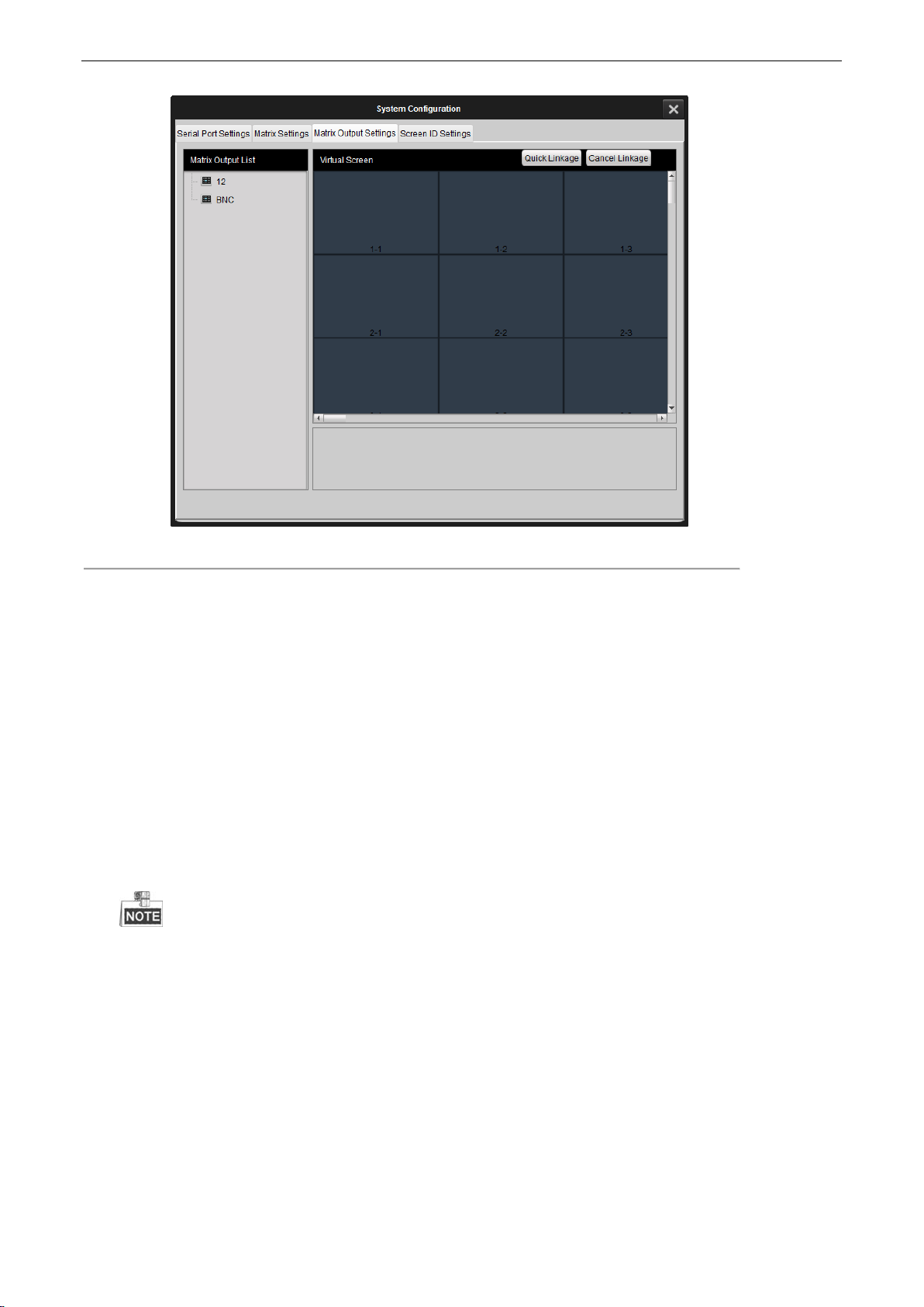
Click Matrix Output Settings to enter the matrix output settings page. You can bind the matrix
output with any of the screen monitor.
Steps:
1. Select a matrix from the Matrix Output List. Click and drag it to any of the virtual screen on the
right panel of the page.
3.5.3 Matrix Output Settings
Purpose:
27
LCD Monitor User Manual
Figure 3. 32 Matrix Output Settings
2. To cancel a linkage, select a matrix linked virtual screen, and click Cancel Linkage to cancel the
linkage.
3.5.4 Screen ID Settings
Purpose:
The screen ID links the physical screen to the virtual screen on the control client, so that when you control the
screen, you can control it by clicking the corresponding screen location on the screen.
Steps:
1. Click Screen ID Settings to enter the page.
2. Click Start Match to pop up an attribute code on the physical screen.
The screen ID code is the code used to define the screen.
3. Select a virtual screen of the corresponding location with the physical screen settings.
4. Input one attribute code you just saw on the physical screen into the textbox on the virtual screen.
5. Click OK, and then the physical screen and the virtual screen are linked..
6. Click End Match to finish the linkage settings.
After the linking setting, when you choose the virtual screen you know clearly which one you are controlling.
28

LCD Monitor User Manual
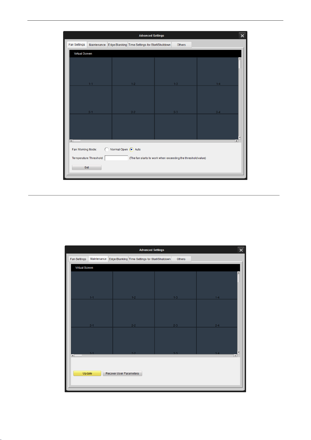
Click Fan Settings to enter the fan settings page.
Steps:
1. Click on a virtual screen to be controlled.
2. Select Normally Open or Auto as the fan working mode for the screen.
3. (Optional) If Auto is selected, you must set the threshold of the temperature triggering the fan to work.
4. Click Set to save the settings.
Figure 3. 33 Screen ID Settings
The linking of the attribute code is necessary for the first commissioning of the video wall. You can also set
the screen linking with an infrared remote control or the dial switch on the rear panel of the device.
3.6 Advanced Settings
Click Advanced Settings to enter the advanced settings page. You can do fan settings, maintenance, edge blanking,
time settings and other operations.
3.6.1 Fan Settings
Purpose:
29
LCD Monitor User Manual
Figure 3. 34 Fan Settings
Click Maintenance to enter the maintenance page. You can reset the device on this page.
Figure 3. 35 Maintenance Interface
3.6.2 Maintenance
Purpose:
30

Update
Insert the USB disk which contains update program in the screen’s back panel. Click Maintenance to enter
the maintenance interface. Select the screen you want to update and click Update to finish the screen
update.
Recover User Parameters
Select a screen needs to be recovered, and click Recover User Parameters to complete the settings.
The device then reboots automatically. All the parameters except the serial number are recovered to the
default.
3.6.3 Edge Blanking
Click Edge Blanking to enter the configuration page. The edge of the image is shielded after configuring the
horizontal and vertical size of the image.
Steps:
1. Select a screen needs to be configured.
2. Check the Enable check box to enable the edge blanking.
3. Input the required horizontal and vertical size of the margin you want to shield.
4. Click Set to complete the settings.
Figure 3. 36 Edge Blanking Interface
Purpose:
LCD Monitor User Manual
31

LCD Monitor User Manual
3.6.4 Time Settings
Purpose:
The time settings are for the screen timed startup and shutdown.
You can set the schedule by week.
Steps:
1. Choose Draw Time Segment By Week and move the cursor to draw the time segment.
2. Select the time segment.
3. You can click the button to copy the same setting to other days by selecting the green area first.
4. Click OK to finish copy.
Figure 3. 37 Time Settings (1)
5. Select the time frame and click to delete it.
6. Click to delete all.
32

LCD Monitor User Manual
Figure 3. 38 Time Settings (2)
You can also set it day by day.
Steps:
1. Choose Input Working Time Manually from the drop down list.
2. Edit the time you want the screen to start up or shut down.
3. Check the checkbox to enable it.
4. Click to delete it.
33

LCD Monitor User Manual
Click Others to enter the page. You can set the no-signal screen mode and OSD menu on this page.
No-Signal Screen Mode
Steps:
1. Select Black, Blue or Show Logo to change the screen to be blue, black and display a logo respectively when
there is no video signal received.
2. Click Set to save the settings. After set the settings, the screen change to the status you set.
OSD Menu
Steps:
1. Select language, transparency and disappearance time for the OSD menu.
2. Click Set to complete the settings.
Figure 3. 39 Time Settings (3)
You can set the power-on delay time to have the screen opening successively to avoid the power fault caused
by the simultaneously bulk startup.
Figure 3. 40 Set Power-On Delay Time
3.6.5 Others
Purpose:
34

LCD Monitor User Manual
Figure 3. 41 Others Settings Interface
35

4.1 Specifications
Model
Monitor
DS-D2046NL-B
DS-D2046NH-B
Display
Diagonal Size(inch)
46"
Backlight
LED Backlight (Direct type)
Resolution
1920×1080
Color
16.7M
Visual Angle
Horizontal:178°, Vertical:178°
Response Time
8 ms (G to G)
Contrast
4500:1
Brightness
500 cd/m
2
800 cd/m
2
Dot Pitch
0.021" (0.53 mm)
Color Saturation
92%
Display Area
40.08" (H) × 22.55" (V)
Seam Size
Bi-side Seam
0.21" (5.3mm)
0.22" (5.5mm)
Interface
Video Input Interface
VGA × 1, DVI × 1, BNC × 1, YPbPr × 1, HDMI × 1
Video Output Interface
VGA × 1, DVI × 1, BNC × 2
Control Interface
RJ45 for RS-232
Power
Power Dissipation
111W
139W
Power Requirement
AC 90 to 264 V, 50/60 Hz
Working
Environment
Working Life
≥ 60,000 Hours
Operating Temperature
0º C to 40º C (32º F to 104º F)
Operating Humidity
10% to 85% (No Condensation)
Frame Width
0.14" (Left/Upper), 0.07"
(Right/Lower)
0.15" (Left/Upper), 0.07"
(Right/Lower)
Dimension (W × H ×
D)
40.31" × 22.8" × 5.2"
40.31" × 22.77" × 4.48"
DS-D2046NL-B/ DS-D2046NH-B
LCD Monitor User Manual
Appendix Chapter 4
36

DS-D2046NH-B/Z
Model
Monitor
DS-D2046NH-B/Z
Display
Diagonal Size(inch)
46"
Backlight
LED Backlight (Direct type)
Resolution
1920 × 1080
Color
16.7 M
Visual Angle
Horizontal: 178°, Vertical: 178°
Response Time
6.5 ms (G to G)
Contrast
4000:1
Brightness
700 cd/m
2
Dot Pitch
0.021" (0.53 mm)
Color Saturation
92%
Display Area
40.08" (H)×22.55" (V)
Seam Size
Bi-side Seam
0.21" (5.4 mm)
Interface
Video Input Interface
VGA × 1, DVI × 1, BNC × 1, YPbPr × 1
Video Control Interface
RJ45 for RS-232
Power
Power Consumption
139W
Power Requirement
100 to 240V AC, 50/60Hz
Working
Environment
Working Life
≥ 60,000 Hours
Operating Temperature
0º C to 40º C (32º F to 104º F)
Operating Humidity
10% to 90% (Non-condensing)
Physical
Features
Frame Width
0.15" (Left/Upper), 0.071" (Right/Lower)
Dimension (W × H ×
D)
40.30" × 22.77" × 4.47"
LCD Monitor User Manual
37

DS-D2046NL-C/DS-D2046NH-C
Model
Monitor
DS-D2046NL-C
DS-D2046NH-C
Display
Diagonal Size (inch)
46"
Resolution
1920 × 1080
Panel
S-PVA
Backlight
LED Backlight (Direct type)
Display Area
40.08" (H) × 22.55" (V)
Dot Pitch
0.021" (0.53 mm)
Color
16.7 M
Color Saturation
92%
Contrast
4500:1
Brightness
500 cd/m2
800 cd/m2
Response time
8 ms (G to G)
Visual Angle
Horizontal:178°; Vertical:178°
Working Life
≥ 60,000 Hours
Interface
Video Input Interface
VGA × 1, DVI × 1, BNC × 1, YPbPr × 1, HDMI × 1
Video Output Interface
VGA × 1,DVI × 1,BNC × 2
Control Interface
In: RS-232, Out: RS-232 × 2
Power
Power Requirement
90 to 264 V AC
Power Dissipation
139 W
Physical Feature
Dimension (W × H ×
D)
40.24" × 22.7" × 4.74"
Physical Seam
0.14" (3.5 mm)
Frame Width
0.09" (Left/Upper), 0.05" (Right/lower)
Working
Environment
Operating Temperature
0º C to 40º C (32º F to 104º F)
Operating Humidity
10% to 85% (Non-condensing)
LCD Monitor User Manual
38

DS-D2046NL-B/Z
Model
Monitor
DS-D2046NL-B/Z
Display
Diagonal Size (inch)
46"
Resolution
1920 × 1080
Color
16.7M
Visual Angle
Horizontal:178°;Vertical: 178° (CR ≥10)
Response time
6.5 ms (G to G)
Contrast
4500:1
Brightness
500 cd/m2
Dot Pitch
0.021" (0.53 mm)
Color Saturation
92%
Display Area
40.08" (H) × 22.55" (V)
Seam Size
Bi-side Seam
0.21" (5.4 mm)
Interface
Video Input Interface
VGA × 1, DVI × 1, BNC × 1, YPbPr × 1
Video Control Interface
RJ45 for RS-232
Power
Power Dissipation
103W
Power Requirement
100 to240 V AC, 50/60Hz
Working
Environment
Working Life
≥ 60,000 Hours
Operating Temperature
0º C to 40º C (32º F to 104º F)
Operating Humidity
10% to 90%
Frame Width
0.14" (Left/Upper), 0.08" (Right/Lower)
Dimension (W×H×D)
40.30" × 22.77" × 4.47"
LCD Monitor User Manual
39

DS-D2055NL/DS-D2055NH
Model
Monitor
DS-D2055NL
DS-D2055NH
Display
Diagonal Size (inch)
55"
Backlight
LED Backlight (Direct type)
Resolution
1920 × 1080
Color
16.7 M
Visual Angle
Horizontal: 178°, Vertical: 178°
Response Time
8ms (G to G)
Contrast
4000:1
Brightness
500 cd/m
2
800 cd/m
2
Dot Pitch
0.025" (0.63 mm)
Color Saturation
92%
Display Area
47.62" (H) × 26.79" (V)
Seam Size
Bi-side Seam
0.22" (5.5mm)
0.21" (5.3mm)
Interface
Video Input Interface
VGA × 1, DVI × 1, BNC × 1, YPbPr × 1, HDMI × 1
Video Output Interface
VGA × 1, DVI × 1, BNC × 2
Control Interface
RJ45 for RS-232
Power
Power Dissipation
145 W
190W
Power Requirement
100 to 230 V AC
Working
Environment
Working Life
≥ 60,000 Hours
Operating Temperature
0º C to 40º C (32º F to 104º F)
Operating Humidity
10% to 85% (Non-condensing)
Frame Width
0.15" (Left/Upper), 0.07"
(Right/lower)
0.14" (Left/Upper), 0.067"
(Right/lower)
Dimension (W × H ×
D)
47.85" × 27.01" × 5.08"
47.85" × 27.02" × 4.48"
LCD Monitor User Manual
40
DS-D2055NL-B
Model
Monitor
DS-D2055NL-B
Display
Diagonal Size (inch)
55"
Resolution
1920 × 1080
Panel
S-PVA
Backlight
LED Backlight (Direct type)
Display Area
47.62" (H) × 26.79" (V)
Dot Pitch
0.025" (0.63 mm)
Color
16.7 M
Color Saturation
92%
Contrast
4000:1
Brightness
500 cd/m2
Response Time
8ms (G to G)
Visual Angle
Horizontal: 178°; Vertical: 178°
Working Life
≥ 60,000 Hours
Interface
Video Input Interface
VGA × 1,DVI × 1,BNC × 1,YPbPr × 1,HDMI × 1
Video Output Interface
VGA × 1,DVI × 1,BNC × 2
Control Interface
RJ45 for RS-232
Power
Power Requirement
AC 90 to 264 V
Power Dissipation
192 W
Physical
Feature
Dimension (W × H × D)
47.78" × 26.94" × 4.44"
Physical Seam
0.14" (3.5 mm)
Frame Width
0.09" (Left/Upper), 0.047" (Right/lower)
Working
Environment
Operating Temperature
0º C to 40º C (32º F to 104º F)
Operating Humidity
10% to 85% (Non-condensing)
LCD Monitor User Manual
41

DS-D2055NH-B
Model
Joint Monitor
DS-D2055NH-B
Display
Diagonal Size(inch)
55"
Resolution
1920 × 1080
Backlight
LED (Direct Type)
Color
16.7 M
Visual Angle
Horizontal:178°, Vertical:178°
Response Time
8 ms (G to G)
Contrast
4000:1
Brightness
800 cd/m
2
Dot Pitch
0.025" (0.63 mm)
Color Saturation
92%
Display Area
47.62" (H) × 26.79" (V)
Seam Size
Bi-side Seam
0.14" (3.5 mm)
Interface
Video Input Interface
VGA × 1, DVI × 1, BNC × 1, YPbPr × 1, HDMI × 1
Video Output Interface
VGA × 1, DVI × 1, BNC × 2
Control Interface
RJ45 for RS-232
Power
Power Requirement
AC 90 to 264 V
Power Dissipation
192 W
Working
Environment
Operating Temperature
0º C to 40º C (32º F to 104º F)
Operating Humidity
10% to 85% (Non-condensing)
Physical
Property
Working Life
≥ 60,000 Hours
Dimension (W × H × D)
47.78" × 26.94" × 4.38"
Frame Width
0.09" (Left/Upper), 0.047" (Right/Lower)
LCD Monitor User Manual
42
DS-D2055NL/Y
Model
Joint Monitor
DS-D2055NL/Y
Display
Diagonal Size (inch)
55"
Resolution
1920 × 1080
Color
16.7 M
Visual Angle
Horizontal:178°, Vertical: 178° (CR≥10)
Response Time
8 ms (G to G)
Contrast
4000:1
Backlight
500 cd/m2
Dot Pitch
0.008" (H) × 0.025" (V)
Color Saturation
92%
Display Area
47.62" (H) × 26.79" (V)
Seam Size
Bi-side Seam
0.22" (5.5 mm)
Interface
Video Input Interface
VGA × 1, DVI × 1, BNC × 1, YPbPr×1
Control Interface
RJ45 for RS-232
Power
Power Dissipation
171W
Power Requirement
AC 100 to 240V, 50/60 Hz
Working
Environment
Working Life
≥ 60,000 Hours
Operating Temperature
0º C to 40º C (32º F to 104º F)
Operating Humidity
10% to 90%
Frame Width
0.14" (Left/Upper), 0.073" (Right/Lower)
Dimension (W × H×D)
47.85" × 27.02" × 2.26"
LCD Monitor User Manual
43

Input Resolution
Video Input
Resolution
Signal
Resolution
CVBS/YPbPr
PAL, TSC
VGA
XGA/60HZ, SXGA/60HZ, 720P/60HZ, 720P/50HZ, 1080P/60HZ,
1080P/50HZ, UXGA/60HZ
DVI/HDMI
XGA/60HZ, SXGA/60HZ, 720P/60HZ, 720P/50HZ, 1080P/60HZ,
1080P/50HZ, 1080I/60HZ, 1080I/50HZ, UXGA/60HZ
LCD Monitor User Manual
44

LCD Monitor User Manual
Phenomenon
Solutions
Unable to power on (power indicator
is off)
1. Check if the power cable is damaged;
2. Check if the power supply is connected;
3. Confirm the power switch is ON;
4. Check if the power switch is damaged;
5. Check if the safety fuse is fused.
All the Screens are out of control
1. Check if the port number of the montage software is correct.
2. Check if the serial line is damaged, and the interface has a
good contact with the device and the computer.
3. Check if the computer serial is good by change to another
computer to have a try.
4. Check if the address configurations of the screens are
correct. Please refer to the address settings.
Some of the screens are out of control.
1. Check if the address configuration of the specific screen is
correct.
2. Check if the sole control to the specific screen is able to
work.
Single or multiple devices provide no
VGA/DVI input.
1. Check if the contact of the screen and the signal interface is
good.
2. Test with another VGA/DVI cable.
3. The device configuration is in correct input status.
4. The input signal is between the input ranges.
5. If the DVI input is selected, please make sure there is a
DDC with the output.
There are Image display exceptions.
1. Replace with the new cables.
2. Add a signal amplifier.
3. If there is an overexposure or underexposure of the image,
please adjust the brightness of the image.
4. If there are stripes displayed on the screen, please check the
device connections or ask to repair or exchange the device.
5. If there is a color deviation of the image, please check the
device connections, or restore the image settings to the default.
The remote control cannot control the
device.
1. Check and replace the battery.
2. Clean the controller with Professional guidance.
3. Ask to repair or exchange the controller.
There is no response from the device
while doing software control
1. Check the device connections.
2. Please ensure that the COM port of the host PC is the same
as which of the software.
3. Check whether the device IP address is correct.
4. Connect the maintenance point for technical support.
4.2 Trouble Shootings
45
 Loading...