


AVR 430
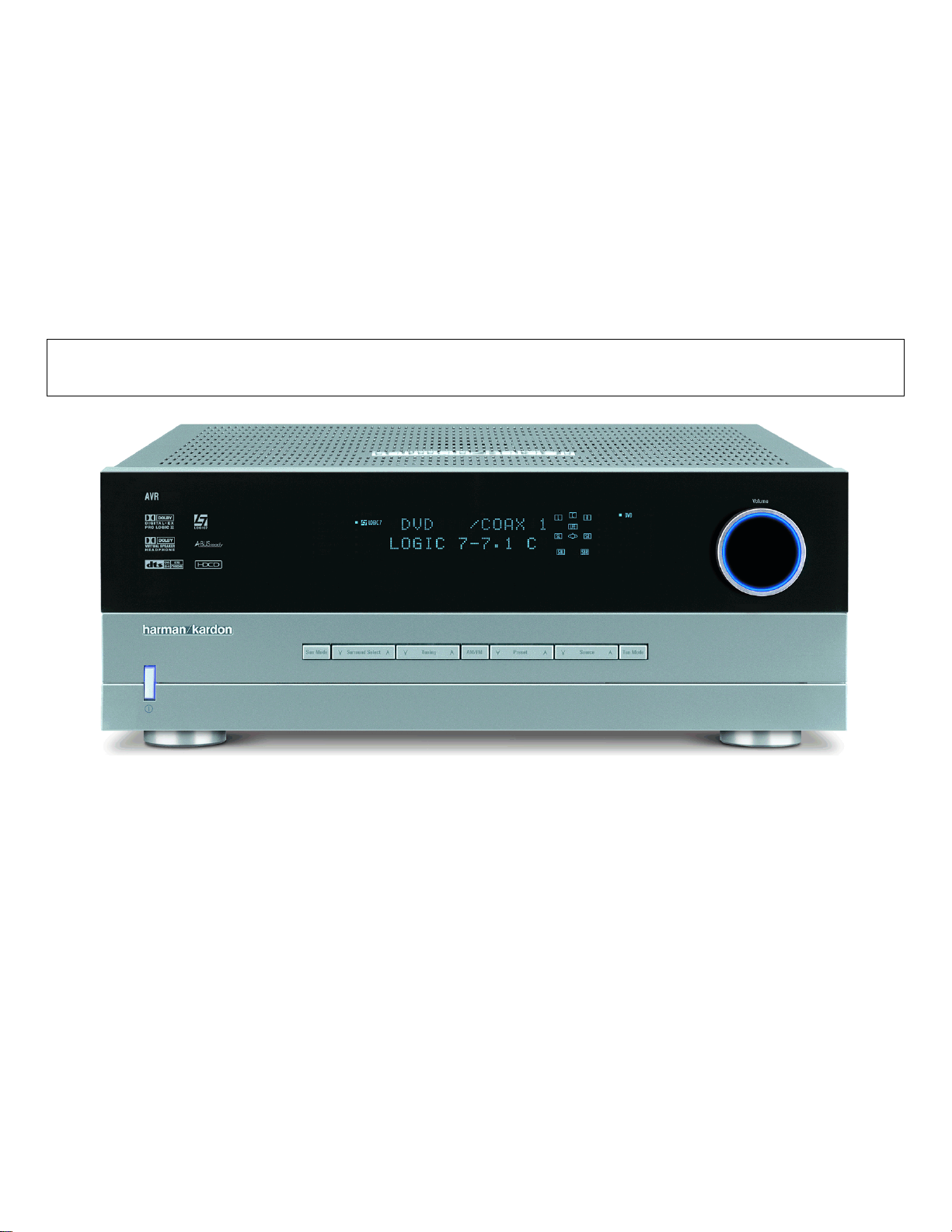
harman/kardon
AVR430
7 X 65W 7.1 CHANNEL A/V RECEIVER
AVR630
7 X 75W 7.1 CHANNEL A/V RECEIVER
SERVICE MANUAL
ESD WAR NI N G ……………………………….2
LEAKAGE TESTING……………….…..…....3
AVR430 BASIC SPECIFICATIONS………..4
AVR630 BASIC SPECIFICATIONS………..5
FRON T P A NE L C ON T R O L S ………..…..…..6
REAR PANEL CONNECTIONS…………. …9
REMOTE CONTROL FUNCTIONS……….12
TROUBLESHOOTING GUIDE…………….16
PROCESSOR RESET………………………16
SERVICE PROCE DURE…………………..17
BULLETIN HK2004-04……………………..20
TECH TIP HKTT2004-03…………………..23
TECH TIP HKTT2003-01…….…………….27
Woodbur y, New York 11797 Rev1 7/ 2005
CONTENTS
BLOCK DIAGRAM…………………….….…28
EXPLODED VIEW…………………….….…29
EXPLODED VIEW PARTS LIST…….….
AVR630 MECHANICAL PARTS LIST…….32
AVR630 ELECTRICAL PARTS LIST……..34
AVR430 MECHANICAL PARTS LIST…….54
AVR430 ELECTRICAL PARTS LIST……..56
SEMICONDUCTO R PINOUTS………… ....7 5
PCB DRAWINGS……………….…………103
SCHEMATICS……………………………..114
WIRING DIAGRAM……………………..…125
PACKING………………………………..…126
harman/kardon, Inc.
250 Crossways Park Dr.
…30
AVR430/AVR630 harman/kardon
2
Some semiconductor (solid state) devices can be damaged easily by static electricity. Such components commonly are called
Electrostatically Sensitive (ES) Devices. Examples of typical ES devices are integrated circuits and some field effect transistors and
semiconductor "chip" components.
The following techniques should be used to help reduce the incidence of component damage caused by static electricity.
1. Immediately before handling any semiconductor component or semiconductor-equipped assembly, drain off any electrostatic charge on
your body by touching a known earth ground. Alternatively, obtain and wear a commercially available discharging wrist strap device,
which should be removed for potential shock reasons prior to applying power to the unit under test.
2. After removing an electrical assembly equipped with ES devices, place the assembly on a conductive surface such as aluminum foil, to
prevent electrostatic charge build-up or exposure of the assembly.
3. Use only a grounded-tip soldering iron to solder or unsolder ES devices.
4. Use only an anti-static solder removal device. Some solder removal devices not classified as "anti-static" can generate electrical charges
sufficient to damage ES devices.
5. Do not use freon-propelled chemicals. These can generate electrical change sufficient to damage ES devices.
6. Do not remove a replacement ES device from its protective package until immediately before you are ready to install it. (Most replacement
ES devices are packaged with leads electrically shorted together by conductive foam, aluminum foil or comparable conductive material.)
7. Immediately before removing the protective material from the leads of a replacement ES device, touch the protective material to the
chassis or circuit assembly into which the device will be installed.
CAUTION :
8. Minimize bodily motions when handling unpackaged replacement ES devices. (Otherwise harmless motion such as the brushing together
or your clothes fabric or the lifting of your foot from a carpeted floor can generate static electricity sufficient to damage an ES devices.
Be sure no power is applied to the chassis or circuit, and observe all other safety precautions.
Each precaution in this manual should be followed during servicing.
Components identified with the IEC symbol in the parts list are special significance to safety. When replacing a component identified with
, use only the replacement parts designated, or parts with the same ratings or resistance, wattage, or voltage that are designated in the
parts list in this manual. Leakage-current or resistance measurements must be made to determine that exposed parts are acceptably
insulated from the supply circuit before retuming the product to the customer.
AVR430/AVR630 harman/kardon
3
Before returning the unit to the user, perform the following safety checks :
1. Inspect all lead dress to make certain that
leads are not pinched or that hardware is not
lodged between the chassis and other metal
parts in the unit.
2. Be sure that any protective devices such as
nonmetallic control knobs, insulating fish-
papers, cabinet backs, adjustment and
compartment covers or shields, isolation
resistor-capacity networks, mechanical
insulators, etc. Which were removed for the
servicing are properly re-installed.
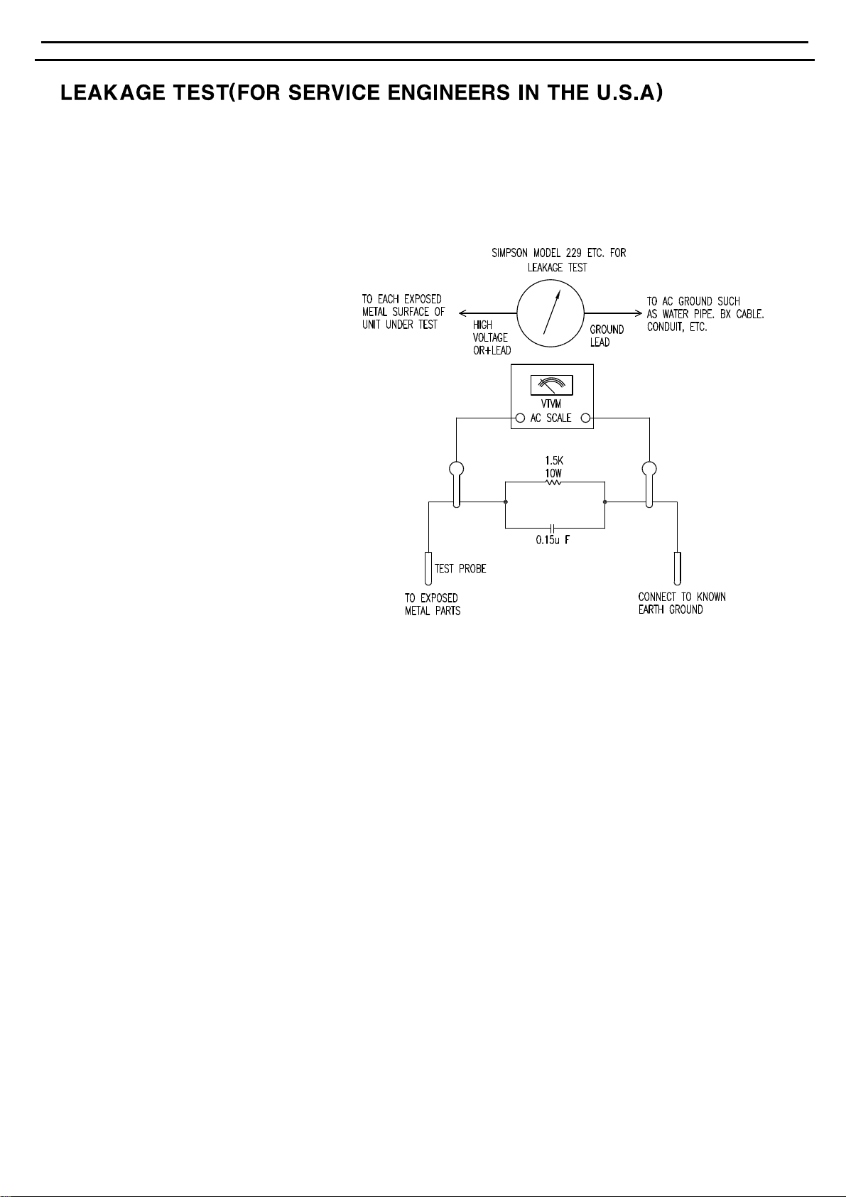
3. Be sure that no shock hazard exists ; check for leakage
current usingSimpson Model 229 Leakage Tester,standard
equipment item No. 21641, RCA Model WT540A or use
alternate method as follows : Plug the power cord directly
Into a 120 volt AC receptacle (do not use an Isolation
Transformer for this test). Using two clip leads, connect a
1500 ohms,10watt Resistor paralleledby a 0.15uF capacitor, inseries with all exposedmetal cabinet partsand a known earth ground,such
as a water pipe or conduit. Use a VTVM or VOM with 1000 ohms per volt, or higher sensitivity to measure the AC voltage drop across the
resistor. (See diagram) Move the resistor connection to each exposed metal part having a return path to the chassis (antenna, metal,
cabinet, screwheads, knobsand controlshafts, escutcheon,etc.) andmeasure the AC voltage drop across the resistor. (Thistest shouldbe
performed withthe 0.35 voltRMS or moreis excessive andindicates a potentialshock hazard whichmust be correctedbefore returning the
unit to the owner.

AVR 430 TECHNICAL SPECIFICATIONS
Audio Section
Stereo Mode
Continuous Average Power (FTC)
80 Watts per channel, 20Hz–20kHz,
@ <0.07% THD, both channels driven into 8 ohms
Seven-Channel Surround Modes
Power per Individual Channel
Front L&R channels:
65 Watts per channel
@ <0.07% THD, 20Hz–20kHz into 8 ohms
Center channel:
65 Watts @ <0.07% THD, 20Hz–20kHz into 8 ohms
Surround (L & R Side, L & R back) channels:
65 Watts per channel
@ <0.07% THD, 20Hz–20kHz into 8 ohms
Input Sensitivity/Impedance
Linear (High-Level) 200mV/47k ohms
Signal-to-Noise Ratio (IHF-A) 95dB
Surround System Adjacent Channel Separation
Pro Logic I/II 40dB
Dolby Digital (AC-3) 55dB
DTS 55dB
Frequency Response
@ 1W (+0dB, –3dB) 10Hz –130kHz
High Instantaneous
Current Capability (HCC) ±40 Amps
Transient Intermodulation
Distortion (TIM) Unmeasurable
Slew Rate 40V/µsec
FM Tuner Section
Frequency Range 87.5–108.0MHz
Usable Sensitivity IHF 1.3µV/13.2dBf
Signal-to-Noise Ratio Mono/Stereo 70/68dB
Distortion Mono/Stereo 0.2/0.3%
Stereo Separation 40dB @ 1kHz
Selectivity ±400kHz, 70dB
Image Rejection 80dB
IF Rejection 90dB
AM Tuner Section
Frequency Range 520–1720kHz
Signal-to-Noise Ratio 45dB
Usable Sensitivity Loop 500µV
Distortion 1kHz, 50% Mod 0.8%
Selectivity ±10kHz, 30dB
Video Section
Television Format NTSC
Input Level/Impedance 1Vp-p/75 ohms
Output Level/Impedance 1Vp-p/75 ohms
Video Frequency Response
(Composite and S-Video) 10Hz–8MHz (–3dB)
Video Frequency Response
(Component Video) 10Hz–50MHz (–3dB)
General
Power Requirement AC 120V/60Hz
Power Consumption 59W idle, 940W at rated power output
(7 channels driven)
Dimensions Product Shipping
Width 17.3 inches (440mm) 20.1 inches (510mm)
Height 6.5 inches (165mm) 10 inches (254mm)
Depth 17.1 inches (435mm) 22.2 inches (565mm)
Weight 39 lb (17.7kg) 45 lb (20.4kg)
Depth measurement includes knobs, buttons and terminal connections.
Height measurement includes feet and chassis.
All features and specifications are subject to change without notice.
Harman Kardon, Power for the Digital Revolution and Logic 7 are registered trademarks of
Harman International Industries, Incorporated.
is a trademark of Harman International Industries, Incorporated (patent no. 5,386,478).
*Manufactured under license from Dolby Laboratories. “Dolby,”“Pro Logic” and the
Double-D symbol are trademarks of Dolby Laboratories.
DTS, DTS Surround, DTS-ES and DTS Neo:6 are registered trademarks of Digital Theater Systems, Inc.
VMAx is a registered trademark of Harman International Industries, Incorporated, and is an
implementation of Cooper Bauck Transaural Stereo under patent license.
A-BUS and A-BUS/Ready are registered trademarks of Leisure Tech Electronics Pty Ltd. Australia.
TiVo is a registered trademark of TiVo, Inc.
Replay TV is a registered trademark of SONICblue, Inc.
TECHNICAL SPECIFICATIONS 51
AVR430/AVR630 harman/kardon
4
TM

AVR 630 TECHNICAL SPECIFICATIONS
Audio Section
Stereo Mode
Continuous Average Power (FTC)
90 Watts per channel, 20Hz–20kHz,
@ <0.07% THD, both channels driven into 8 ohms
Seven-Channel Surround Modes
Power per Individual Channel
Front L&R channels:
75 Watts per channel
@ <0.07% THD, 20Hz–20kHz into 8 ohms
Center channel:
75 Watts @ <0.07% THD, 20Hz–20kHz into 8 ohms
Surround (L & R Side, L & R back) channels:
75 Watts per channel
@ <0.07% THD, 20Hz–20kHz into 8 ohms
Input Sensitivity/Impedance
Linear (High-Level) 200mV/47k ohms
Signal-to-Noise Ratio (IHF-A) 95dB
Surround System Adjacent Channel Separation
Pro Logic I/II 40dB
Dolby Digital (AC-3) 55dB
DTS 55dB
Frequency Response
@ 1W (+0dB, –3dB) 10Hz –130kHz
High Instantaneous
Current Capability (HCC) ±50 Amps
Transient Intermodulation
Distortion (TIM) Unmeasurable
Slew Rate 40V/µsec
FM Tuner Section
Frequency Range 87.5–108.0MHz
Usable Sensitivity IHF 1.3µV/13.2dBf
Signal-to-Noise Ratio Mono/Stereo 70/68dB
Distortion Mono/Stereo 0.2/0.3%
Stereo Separation 40dB @ 1kHz
Selectivity ±400kHz, 70dB
Image Rejection 80dB
IF Rejection 90dB
AM Tuner Section
Frequency Range 520–1720kHz
Signal-to-Noise Ratio 45dB
Usable Sensitivity Loop 500µV
Distortion 1kHz, 50% Mod 0.8%
Selectivity ±10kHz, 30dB
Video Section
Television Format NTSC
Input Level/Impedance 1Vp-p/75 ohms
Output Level/Impedance 1Vp-p/75 ohms
Video Frequency Response
(Composite and S-Video) 10Hz–8MHz (–3dB)
Video Frequency Response
(Component Video) 10Hz–50MHz (–3dB)
General
Power Requirement AC 120V/60Hz
Power Consumption 59W idle, 1000W at rated power output
(7 channels driven)
Dimensions Product Shipping
Width 17.3 inches (440mm) 20.1 inches (510mm)
Height 6.5 inches (165mm) 10 inches (254mm)
Depth 17.1 inches (435mm) 22.2 inches (565mm)
Weight 41 lb (18.6kg) 47 lb (21.4kg)
Depth measurement includes knobs, buttons and terminal connections.
Height measurement includes feet and chassis.
All features and specifications are subject to change without notice.
Harman Kardon, Power for the Digital Revolution and Logic 7 are registered trademarks of
Harman International Industries, Incorporated.
is a trademark of Harman International Industries, Incorporated (patent no. 5,386,478).
*Manufactured under license from Dolby Laboratories. “Dolby,”“Pro Logic”and the
Double-D symbol are trademarks of Dolby Laboratories.
DTS, DTS Surround, DTS-ES and DTS Neo:6 are registered trademarks of Digital Theater Systems, Inc.
VMAx is a registered trademark of Harman International Industries, Incorporated, and is an
implementation of Cooper Bauck Transaural Stereo under patent license.
HDCD system manufactured under license from Pacific Microsonics, Inc. This product is
covered by one or more of the following: in the USA: 5,479,168; 5,638,074; 5,640,161; 5,808,574;
5,838,274; 5,854,600; 5,864,311; 5,872,531; and in Australia: 669114. Other patents pending.
A-BUS and A-BUS Ready are registered trademarks of Leisure Tech Electronics Pty Ltd Australia.
TiVo is a registered trademark of TiVo, Inc.
Replay TV is a registered trademark of SONICblue, Inc.
TECHNICAL SPECIFICATIONS 51
AVR430/AVR630 harman/kardon
5
TM
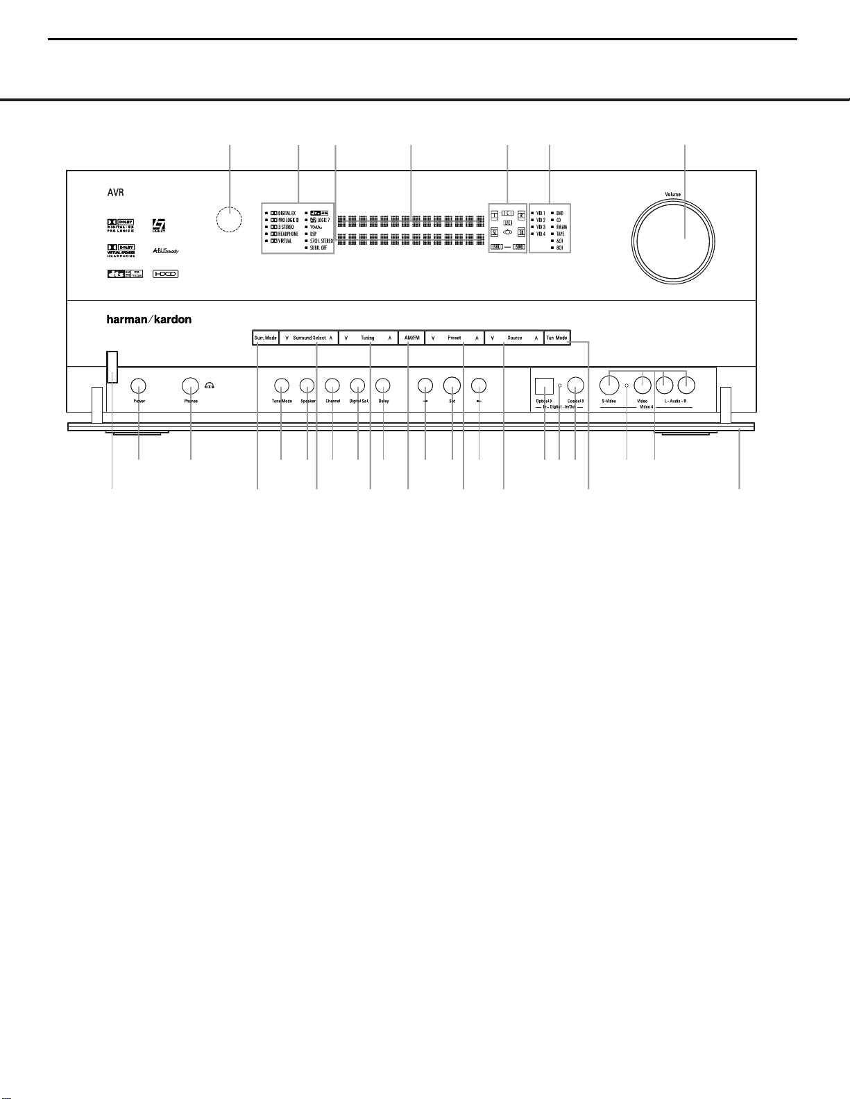
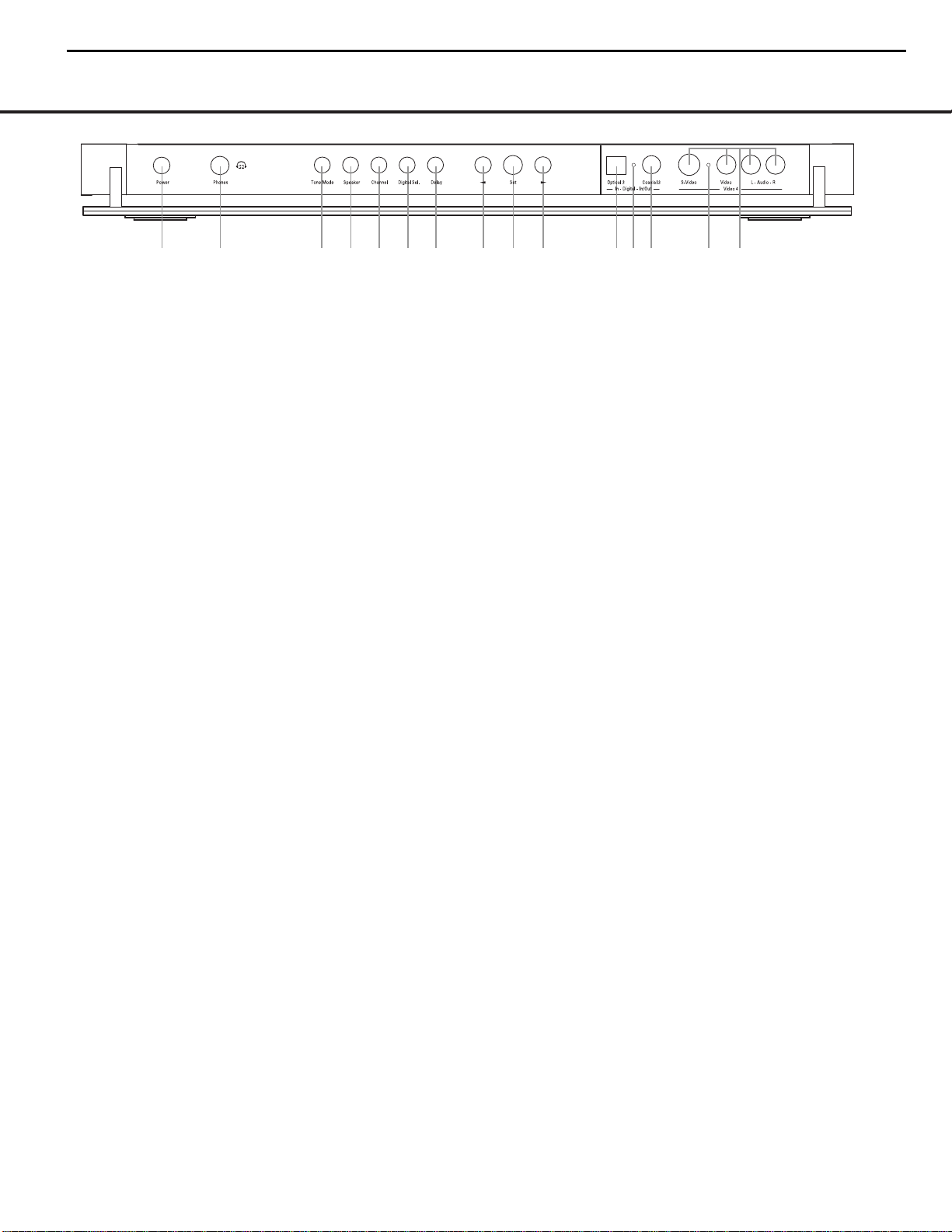
FRONT-PANEL CONTROLS
1 Standby/On Switch
2 Surround Mode Group Selector
3 Surround Mode Selector
4 Tuning Selector
5 Tuner Band Selector
6 Preset Station Selector
7 Input Source Selector
8 Tuning Mode Selector
9 Front Panel Control Door
) Volume Control
! Input Indicators
@ Speaker/Channel Input Indicators
# Upper Display Line
$ Lower Display Line
% Surround Mode Indicators
^ Remote Sensor Window
FRONT-PANEL CONTROLS
FRONT-PANEL CONTROLS 55
The following controls and indicators are available on the AVR 630’s front panel:
The following controls and jacks are located behind the front-panel door. To open the door, place the edge of a finger on the left or right edge of the panel and gently swing the
door down towards you.
A Main Power Switch
B Headphone Jack
C Tone Mode Button
D Speaker Selector Button
E Channel Adjust Selector
F Digital Input Selector
G Delay Adjust Selector
H‹/› Buttons
I Set Button
J Optical 3 Digital Input
K Input/Output Status Indicators
L Coaxial 3 Digital Jack
M Video 4 Audio/Video Jacks
1 Standby/On Switch: When the Main Power
Switch
A
is “ON,” press this button to turn on the
AVR 630; press it again to turn the unit off. Note that
the illumination surrounding the switch will turn blue
when the unit is on.
2 Surround Mode Group Selector: Press this but-
ton to select the top-level group of surround modes.
Each press of the button will select one of the surround mode categories. Once the button is pressed so
that the name of the desired surround mode category
appears in the on-screen display and in the
Lower
Display Line
$, press the Surround Mode
Selector
3 to cycle through the individual modes
available. For example, press this button to select Dolby
modes, and then press the
Surround Mode Selector
3 to choose from the various mode options.
3 Surround Mode Selector: Press this button
to select from among the available surround mode
options for the surround mode category selected.
The specific modes will vary based on the number of
speakers available, the surround mode category and
whether the input source is digital or analog. For example, press the
Surround Mode Group Selector 2
to select a category such as Dolby or Logic 7, and
then press this button to see the specific mode choices
that are available. For more information on mode
selection, see page 31.
NOTE: To make it easier to follow the instructions that refer to this illustration, a larger copy may be downloaded from the Product Support section for this product at
www.harmankardon.com.
2
4
5
6
7
9
!
@
#
%
3
8
A
B
D
E F
G
HH
I
JK KL
M
)
$
^
1
C
2
4
5
6
7
9
!
@
#
%
3
8
A
B
D
E F
G
HH
I
JK KL
M
)
$
^
1
C
AVR430/AVR630 harman/kardon
6
= AVR630 only feature

FRONT-PANEL CONTROLS
6 FRONT-PANEL CONTROLS
4 Tuning Selector: Press the left side of the button
to tune lower-frequency stations and the right side of
the button to tune higher-frequency stations. When
the tuner is in the
MANUAL/MONO mode,
each tap of the Selector will increase or decrease the
frequency by one increment. When the tuner receives
a strong-enough signal for adequate reception,
MANUAL TUNED will appear in the Lower
Display Line
$ and in the on-screen display.When
the tuner is in the
AUTO/STEREO mode,
press the button once, and the tuner will scan for a
station with acceptable signal strength. When the next
higher or lower frequency station with a strong-enough
signal is tuned, the frequency scan will stop and the
Lower Display Line $ and the on-screen display
will indicate
AUTO TUNED. When an FM Stereo
station is tuned, the display will read
AUTO ST
TUNED
. See page 34 for more information on
using the tuner.
5 Tuner Band Selector: Pressing this button will
automatically switch the AVR 630 to the Tuner mode.
Pressing it again will switch between the AM and FM
frequency bands. (See page 34 for more information
on the tuner.)
6 Preset Station Selector: Press this button to
scroll up or down through the list of stations that have
been entered into the preset memory. (See page 34
for more information on tuner programming.)
7 Input Source Selector: Press this button to
change the input by scrolling up or down through the
list of input sources.
8 Tuning Mode Selector: Press this button to select
Auto or Manual tuning. When the button is pressed so
that
AUTO/STEREO appears in the Upper
Display Line
#, the tuner will search for the next sta-
tion with an acceptable signal when the
Tuning
Selector
4wéis pressed. When the button is
pressed so that
MANUAL/MONO appears in the
Upper Display Line #, each press of the Tuning
Selector
4wéwill increase the frequency. (See
page 34 for more information on using the tuner.) This
button may also be used to switch between Stereo and
Mono modes for FM radio reception. When weak
reception is encountered, select the Manual/Mono
tuning mode. Press and hold again to switch back to
Stereo mode. (See page 34 for more information on
using the tuner.)
9 Front-Panel Control Door: To open the door so
that the front-panel jacks and controls behind this door
may be accessed, gently pull the door down and
towards you using either upper corner of the door.
) Volume Control: Tu rn this knob clockwise to
increase the volume, counterclockwise to decrease the
volume. If the AVR 630 is muted, adjusting the volume
control will automatically release the unit from the
silenced condition.
! Input Indicators: One of these indicators will light
to identify the currently selected input. Note that the
entire list will light briefly each time the unit is turned
on as a test.
@ Speaker/Channel Input Indicators: These indi-
cators are multipurpose, indicating both the speaker
type selected for each channel and the incoming datasignal configuration. The left, center, right, right surround
and left surround speaker indicators are composed of
three boxes, while the subwoofer is a single box. The
center box lights when a “small” speaker is selected,
and the two outer boxes light when “large” speakers are
selected. When none of the boxes are lit for the center,
surround or subwoofer channels, no speaker has been
assigned that position. (See page 23 for more informa-
tion on configuring speakers.) The letters inside each
box displays the active input channels. For standard
analog inputs, only the L and R will light, indicating a
stereo input. For a digital source, the indicators will light
to display the channels being received at the digital
input. When the letters flash, the digital input has been
interrupted. (See page 33 for more information on the
Channel Indicators.)
# Upper Display Line: Depending on the unit’s
status, a variety of messages will appear here. In
normal operation, this line will show the current input
source and identify whether an analog or digital input
is in use.When the tuner is selected as the input, this
line will identify the station as AM or FM and show the
frequency and preset number, if any.
$ Lower Display Line: Depending on the unit’s
status, a variety of messages will appear here. In normal operation, the current surround mode will appear
on this line.
% Surround Mode Indicators: One of these
indicators will light to show the surround mode in
use. Depending on the specific combination of input
sources and surround mode selected, more than
one indicator may light. (See page 31 for more
information.)
^ Remote Sensor Window: The sensor behind
this window receives infrared signals from the remote
control. Aim the remote at this area and do not block
or cover it unless an external remote sensor is
installed.
AVR430/AVR630 harman/kardon
7
FRONT-PANEL CONTROLS
FRONT-PANEL CONTROLS 7
The following controls and jacks are located behind the front-panel door. To open the door, place the edge of a finger on the left or right edge of the panel and gently swing the
door down towards you.
A Main Power Switch: Press this switch to apply
power to the AVR 630.When the switch is pressed
in, the unit is placed in a Standby mode, as indicated
by the amber illumination surrounding the
Standby/On
Switch
1. This button MUST be pressed in to
operate the unit. To turn the unit off and prevent the
use of the remote control, this switch should be
pressed until it pops out from the front panel so that
the word “OFF” may be read at the top of the switch.
NOTE: This switch is normally left in the “ON” position.
B Headphone Jack: This jack may be used to lis-
ten to the AVR 630’s output through a pair of headphones. Be certain that the headphones have a standard 1/4" stereo phone plug, or that you use an
adapter, as needed, to convert the plug on your headphones to the 1/4" jack used on the AVR.When the
headphone jack is in use, the main room speakers will
automatically be turned off and the unit will output a
standard stereo signal. You may also use one of the
Dolby Headphone modes for an enhanced listening
experience. For more information on headphone lis-
tening, see page 30.
C Tone Mode Button: This button controls the tone
mode settings, enabling adjustment of the bass and
treble boost/cut. You may also use it to take the tone
controls out of the signal path completely for “flat”
response.The first press of the button displays a
TONE MODE message in the Lower Display
Line
$ and in the on-screen display.To take the
controls out of the signal path, press either of the
‹/› Buttons H until the display reads TONE
OUT
.To change the bass or treble settings, press
the button again until the desired option appears in the
Lower Display Line $ and in the on-screen display
and then press either of the
‹/› Buttons H to
enter the desired boost or cut setting. See page 30
for more information on the tone controls.
D Speaker Selector Button: Press this button to
begin the process of configuring the AVR 630 for the
type of speakers it is being used with. For complete
information on configuring the speaker settings, see
page 23.
E Channel Adjust Selector: Press the button to
begin the process of adjusting the channel level outputs using the source currently playing through your
AVR. For complete information on adjusting the chan-
nel output level, see page 35.
F Digital Input Selector: Press this button to begin
the process of selecting a digital source for use with
the currently selected input. Once the button has been
pressed, use the
‹/› Buttons H to choose the
desired input and then press the
Set Button I to
enter the setting into the unit’s memory. See page 30
for more information on digital audio.
G Delay Adjust Selector: Press this button to begin
the process of adjusting the delay settings for Dolby
surround modes. See page 25 for more information
on delay adjustments.
H‹/› Buttons: When making system configura-
tion changes using the front-panel controls, press
these button to scroll through the available choices
for the option being adjusted.
I Set Button: When making system configuration
changes using the front-panel controls, press this button to enter a setting into the unit’s memory.
J Optical 3 Digital Input: Connect the optical digital
output of an audio or video product to this jack.
K Input/Output Status Indicators: These LED indi-
cators will normally light green to show that the frontpanel
Coaxial 3 Digital Jack L and Video 4
Input/Output Jacks
M are operating as inputs.When
these jacks are configured for use as an output, the
appropriate indicator will turn red to show that the jack
may be used as an output for recording. (See page 34
for more information on configuring the front-panel
jacks as outputs, rather than inputs.)
L Coaxial 3 Digital Jack: Connect the coaxial digi-
tal input or output for a digital audio product such as a
portable audio player or video game to this jack. The
jack is normally an input, but may be switched to an
output for recording using the menu system. See page
34 for more information.
M Video 4 Input/Output Jacks: These audio/video
jacks may be used as either an input or output for
temporary connection to video games or portable
audio/video products such as camcorders and
portable audio players. (See page 34 for more
information on switching these jacks between an
input and output.)
A
B
D
E F
G
HH
I
JK KL
M
C
AVR430/AVR630 harman/kardon
8
= AVR630 only feature
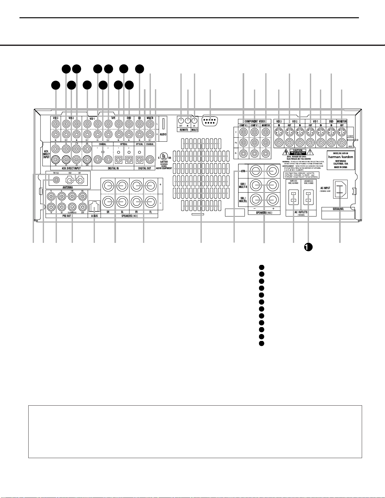
8 REAR-PANEL CONNECTIONS
REAR-PANEL CONNECTIONS
¡ AM Antenna
™ FM Antenna
£ Preamp Outputs
¢ Subwoofer Output
∞ A-BUS Connector
§ Surround Speaker Outputs
¶ Front Speaker Outputs
• Fan Vents
ª Center Speaker Outputs
‚ Surround Back/Multiroom Speaker Outputs
⁄ Switched AC Accessory Outlet
¤ Unswitched AC Accessory Outlet
‹ AC Power Cord Jack
› Video Monitor Outputs
fi DVD Video Inputs
fl Video 1 Video Inputs
‡ Video 1 Video Outputs
° Video 2 Video Inputs
· Video 2 Video Outputs
a Video 3 Video Inputs
b Component Video Monitor Outputs
c Component Video 1 Inputs
d Component Video 2 Inputs
e RS-232 Port
f Multiroom IR Input
g Remote IR Input
h Remote IR Output
i Coaxial Digital Audio Output
j Multiroom Audio Outputs
k Optical Digital Audio Output
CD Audio Inputs
DVD Audio Inputs
Optical Digital Audio Inputs
Tape Inputs
Tape Outputs
Coaxial Digital Audio Inputs
Video 1 Audio Inputs
Video 1 Audio Outputs
Video 2 Audio Inputs
8-Channel Direct Inputs
Video 2 Audio Outputs
Video 3 Audio Inputs
NOTE: To assist in making the correct connections for
multichannel input, output and speaker connections,
all connection jacks and terminals are color-coded
in conformance with the CEA standards as follows:
Front Left: White
Front Right: Red
Center: Green
Surround Left: Blue
Surround Right: Gray
Surround Back Left: Brown
Surround Back Right: Tan
Subwoofer: Purple
Digital Audio: Orange
Composite Video: Yellow
Component Video “Y”: Green
Component Video “Pr”: Red
Component Video “Pb”: Blue
REAR-PANEL CONNECTIONS
8 REAR-PANEL CONNECTIONS
NOTE: To make it easier to follow the instructions that refer to this illustration, a larger copy may be downloaded from the Product Support section for this product at
www.harmankardon.com.
™
£
¢
∞§
¶
•
ª
⁄
fl
fi
›
·
°c
a
e
d
b
hgf
j
k
i
2
‹
‡
38
39
40
41
31
37
36
35
34
33
32
42
¡
‚
AVR430/AVR630 harman/kardon
9
31
32
33
34
35
36
37
38
39
40
41
42

REAR-PANEL CONNECTIONS 9
REAR-PANEL CONNECTIONS
¡ AM Antenna: Connect the AM loop antenna sup-
plied with the receiver to these terminals. If an external
AM antenna is used, make connections to the
AM and
GND terminals in accordance with the instructions sup-
plied with the antenna.
™ FM Antenna: Connect the supplied indoor or an
optional external FM antenna to this terminal.
£ Preamp Outputs: Connect these jacks to an
optional, external power amplifier for applications
where higher power is desired.
¢ Subwoofer Output: Connect this jack to the line-
level input of a powered subwoofer. If an external subwoofer amplifier is used, connect this jack to the subwoofer amplifier input.
∞ A-BUS Connector:
Connect this jack to an optional
A-BUS®-certified remote room keypad or amplifier to
extend the multiroom capabilities of your AVR 630.
See page 38 for more information on A-BUS.
§ Surround Speaker Outputs: Connect these out-
puts to the matching + and – terminals on your surround channel speakers. In conformance with the CEA
color-code specification, the blue terminal is the positive, or “+” terminal that should be connected to the
red (+) terminal on the Surround Left speaker with
older color-coding, while the gray terminal should be
connected to the red (+) terminal on the Surround
Right speaker with the older color-coding. Connect the
black (–) terminal on the AVR to the matching black
negative (–) terminals for each surround speaker. (See
page 16 for more information on speaker polarity.)
¶ Front Speaker Outputs: Connect these outputs
to the matching + or – terminals on your left and right
speakers.When making speaker connections always
make certain to maintain correct polarity by connecting
the color-coded (white for front left and red for front
right) (+) terminals on the AVR 630 to the red (+)
terminals on the speakers and the black (–) terminals
on the AVR 630 to the black (–) terminals on the
speakers. See page 16 for more information on
speaker polarity.
• Fan Vents: These ventilation holes are the output
of the AVR 630’s airflow system. To ensure proper
operation of the unit and to avoid possible damage to
delicate surfaces, make certain that these holes are
not blocked and that there is at least three inches of
open space between the vent holes and any wooden
or fabric surface. It is normal for the fan to remain off
at most normal volume levels. An automatic temperature sensor turns the fan on only when it is needed.
ª Center Speaker Outputs: Connect these outputs
to the matching + and – terminals on your center
channel speaker. In conformance with the CEA colorcode specification, the green terminal is the positive,
or “+” terminal that should be connected to the red
(+) terminal on speakers with the older color-coding.
Connect the black (–) terminal on the AVR to the
black negative (–) terminal on your speaker. (See
page 16 for more information on speaker polarity.)
‚ Surround Back/Multiroom Speaker Outputs:
These speaker terminals are normally used to power
the surround back left/surround back right speakers
in a 7.1 channel system. However, they may also be
used to power the speakers in a second zone, which
will receive the output selected for a multiroom system.
To change the output fed to these terminals from
the default of the Surround Back speakers to the
Multiroom Output, you must change a setting in the
Advanced Menu of the OSD system. See page 36 for
more information on configuring this speaker output. In
normal surround system use, the brown and black terminals are the surround back left channel positive (+)
and negative (–) connections and the tan and black
terminals are the surround back right positive (+) and
negative (–) terminals. For multiroom use, connect the
brown and black SBL terminals to the red and black
connections on the left remote zone speaker and connect the tan and black SBR terminals to the red and
black terminals on the right remote zone speaker.
⁄ Switched AC Accessory Outlet: These outlets
may be used to power any device you wish to have
turned on when the AVR 630 is turned on with the
Standby/On Switch 1.
¤ Unswitched AC Accessory Outlet: This outlet
may be used to power any AC device. The power will
remain on at this outlet regardless of whether the
AVR 630 is on or off.
NOTE: The total power consumption of all devices
connected to the accessory outlets should not exceed
100 watts.
‹ AC Power Cord Jack: Connect the AC power
cord to this jack when the installation is complete.
To ensure safe operation, use only the power cord
supplied with the unit. If a replacement is required,
it must be of the same type and capacity.
› Video Monitor Outputs: Connect these jacks to
the composite or S-Video input of a TV monitor or
video projector to view the on-screen menus and the
output of any standard video source selected by the
receiver’s video switcher.
fi DVD Video Inputs: Connect the composite or S-
Video outputs of a DVD player or other video source
to these jacks.
fl Video 1 Video Inputs: Connect the composite or
S-Video PLAY/OUT jacks of a VCR or other video
source to these jacks.
‡ Video 1 Video Outputs: Connect the composite
or S-Video REC/IN jacks of a VCR or other video
recording device such as a DVD recorder or PVR to
these jacks.
° Video 2 Video Inputs: Connect the composite or
S-Video PLAY/OUT jacks of a VCR or other video
source to these jacks.
· Video 2 Video Outputs: Connect the composite
or S-Video REC/IN jacks of a VCR or other video
recording device such as a DVD recorder or PVR to
these jacks.
a Video 3 Video Inputs: Connect the composite or
S-Video PLAY/OUT jacks of a VCR or other video
source to these jacks.
b Component Video Monitor Outputs: Connect
these outputs to the component video inputs of a
video projector or monitor. When a source connected
to one of the
Component Video Inputs cd is
selected the signal will be sent to these jacks.
c Component Video 1 Inputs: These inputs may
be used with any source device equipped with analog
Y/Pr/Pb or RGB component video outputs.The factory
default is for these jacks to be a linked to the DVD
input, but you may change the setting at any time
through the
IN/OUT SETUP menu. See
page 21 for more information on configuring the
component video inputs.
d Component Video 2 Inputs: These inputs may
be used with any video source device equipped with
analog Y/Pr/Pb or RGB component video outputs. The
factory default is for these jacks to be a linked to the
Video 2 input, but you may change the setting at any
time through the
IN/OUT SETUP menu. See
page 21 for more information on configuring the component video inputs.
e RS-232 Port: This jack may be used to control
the AVR 630 over a bi-directional RS-232 serial
control link to a compatible computer or programmable
remote control system. Due to the complexity of
programming RS-232 commands we strongly
recommend that connections to this port for
control purposes be made by a trained and qualified
technician. This jack may also link to a compatible
computer to upgrade the software and operating system of the AVR 630 when appropriate upgrades are
available.
f Multiroom IR Input: Connect the output of an IR
sensor in a remote room to this jack to operate the
AVR 630’s multiroom control system.
AVR430/AVR630 harman/kardon
10

REAR-PANEL CONNECTIONS
10 REAR-PANEL CONNECTIONS
g Remote IR Input: If the AVR 630’s front-panel
IR sensor is blocked due to cabinet doors or other
obstructions, an external IR sensor may be used.
Connect the output of the sensor to this jack.
h Remote IR Output: This connection permits the
IR sensor in the receiver to serve other remote controlled devices. Connect this jack to the “IR IN” jack on
Harman Kardon (or other compatible) equipment.
i Coaxial Digital Audio Output: Connect this jack
to the coaxial digital input of a CD-R/RW, MiniDisc or
other compatible digital recorder.
j Multiroom Audio Outputs: Connect these jacks
to the optional external audio power amplifier and
video distribution system that delivers the source
selected for multizone distribution.
k Optical Digital Audio Output: Connect this jack
to the optical digital input connector on a CD-R/RW,
MiniDisc or other compatible digital recorder.
CD Audio Inputs: Connect these jacks to the
left/right analog audio output of a compact disc player
or CD changer or other audio source.
DVD Audio Inputs: Connect the left/right analog
outputs of a DVD player or other audio source to
these jacks.
Optical Digital Audio Inputs: Connect the opti-
cal digital output from a DVD player, HDTV receiver,
the S/P-DIF output of a compatible computer sound
card playing MP3 files or streams, LD player or CD
player to these jacks.The signal may be a Dolby Digital
signal, a DTS signal or a standard PCM digital source.
Tape Inputs: Connect these jacks to the Play/Oout
jacks of an audio recorder.
Tape Outputs: Connect these jacks to the
Record/Input jacks of an audio recorder.
Coaxial Digital Audio Inputs: Connect the coax
digital output from a DVD player, HDTV receiver, the
S/P-DIF output of a compatible computer
sound card
playing MP3 files or streams, LD player
or CD player to
these jacks.The signal may be a Dolby Digital signal,
DTS signal or a standard PCM digital source. Do not
connect the RF digital output of an LD player to
these jacks.
Video 1 Audio Inputs: Connect the left/right
PLAY/OUT audio output jacks on a VCR or other video
source to these jacks.
Video 1 Audio Outputs: Connect the left/right
REC/IN audio input jacks on a VCR or other video
source to these jacks.
Video 2 Audio Inputs: Connect the left/right
PLAY/OUT audio output jacks on a VCR or other video
source to these jacks.
8-Channel Direct Inputs: These jacks are used
for connection to source devices such as DVD-Audio
or SACD players with discrete analog outputs.
Depending on the source device in use, all eight jacks
may be used, though in many cases only connections
to the front left/right, center, surround left/right and
LFE (subwoofer input) jacks will be used for standard
5.1 audio signals.
Video 2 Audio Outputs: Connect the left/right
REC/IN audio input jacks on a VCR or other video
source to these jacks.
Video 3 Audio Inputs: Connect the left/right
PLAY/OUT audio output jacks on a VCR, PVR, cable
set-top, satellite receiver, HDTV receiver or other video
source to these jacks.
AVR430/AVR630 harman/kardon
11
31
32
37
38
39
40
41
42
33
34
35
36
MAIN REMOTE CONTROL FUNCTIONS
MAIN REMOTE CONTROL FUNCTIONS 11MAIN REMOTE CONTROL FUNCTIONS 11
0
Power Off Button
1
Power On Button
2
LCD Information Display
3
Input Selectors
4
AVR Selector
5
Test Button
6
DSP Surround Mode Selector
7
Logic 7 Mode Select Button
8
Direct Button
9
Clear Button
A
Numeric Keys
B
Tuning Mode Button
m Dim Button
n Channel Select Button
o Navigation Button
F
Digital Select Button
G
Set Button
H
Volume Up/Down Selectors
I
Transport Fast-Play/Scan Buttons
J
Main Transport Controls
K
Track Skip Up/Down Buttons
L
Preset Up/Down Button
M
Tuning Up/Down Button
N
Disc Skip Button
O
Program Button
P
Light Button
Q
Multiroom Button
Macro Buttons
Sleep Button
Night Mode Button
OSD Button
Tone Control Button
Mute Button
AM/FM Button
Channel Up/Down Selector
Transport Play Buttons
Delay Select Button
Speaker Select Button
Memory Button
Stereo Mode Select Button
DTS Neo:6 Mode Select Button
DTS Digital Mode Select Button
Dolby Mode Select Button
6/8-Channel Input Select
SPL Select Button
EzSet Microphone Sensor
Lens
1
2
3
4
5
6
7
9
A
D
F
H
J
L
N
O
P
Q
M
0
C
K
8
G
B
E
I
AVR
NOTES:
• The function names shown here are each button’s feature when used with the AVR 630. Most
buttons have additional functions when used with other devices.When a button is pressed, the
function name will appear in the bottom line of the
LCD Information Display c.
• The jack on the upper right side of the remote is reserved for future use. Do not remove the
plug provided or connect any device to the jack.
• To make it easier to follow the instructions that refer to this illustration, a larger copy may be
downloaded from the Product Support section for this product at www.harmankardon.com.
AVR430/AVR630 harman/kardon
12

12 MAIN REMOTE CONTROL FUNCTIONS
MAIN REMOTE CONTROL FUNCTIONS
IMPORTANT NOTE: The AVR 630’s remote may
be programmed to control up to eight devices,
including the AVR 630. Before using the remote,
it is important to remember to press the
Input
Selector Button
3
that corresponds to the unit
you wish to operate. In addition, the AVR 630’s
remote is shipped from the factory to operate the
AVR 630 and most Harman Kardon CD or DVD
players and cassette decks.The remote is also
capable of operating a wide variety of other products
using the control codes that are part of the remote.
Before using the remote with other products, follow
the instructions on pages 40 – 49 to program the
proper codes for the products in your system.
It is also important to remember that many of the
buttons on the remote take on different functions,
depending on the product selected using the
Input
Selectors
d. The descriptions shown here primarily
detail the functions of the remote when it is used to
operate the AVR 630.
a Power Off Button: Press this button to place
the AVR 630 or a selected device in the Standby
mode. Note that this will turn off the main room
functions, but if the Multiroom system is activated,
it will continue to function.
1
Power On Button: Press this button to turn on
the power to a device selected by first pressing one of
the
Input Selectors3.
2
LCD Information Display: This two-line screen
displays various information depending on the commands that have been entered into the remote.
3
Input Selectors: Pressing one of these buttons
will perform three actions at the same time. First, if the
AVR 630 is not turned on, this will power up the unit.
Next, it will select the source shown on the button as
the input to the AVR 630. Finally, it will change the
remote control so that it controls the device selected.
After pressing one of these buttons you must press
the
AVR Selector Button 4again to operate the
AVR 630’s functions with the remote.
4
AVR Selector: Pressing this button will switch the
remote so that it will operate the AVR 630's functions. If
the AVR 630 is in the Standby mode, it will also turn the
AVR 630 on.
5
Test Button: Press this button to begin the
sequence used to calibrate the AVR 630’s output
levels. (See page 26 for more information on calibrat-
ing the AVR 630.)
g DSP Surround Mode Selector: Press this
button to select one of the DSP surround modes, such
as VMAx, Hall 1, Hall 2 or Theater. Each press of the
button selects another mode. (See page 31 for more
information on surround modes.)
7
Logic 7 Mode Select Button: Press this button
to select from among the available Logic 7 surround
modes. (See page 31 for the available Logic 7
options.)
8
Direct Button: Press this button when the tuner
is in use to start the sequence for direct entry of a
station’s frequency. After pressing the button, simply
press the proper
Numeric Keys Ato select a
station. (See page 34 for more information on the tuner.)
9
Clear Button: When programming the remote
or using the EzSet feature, press this button to cancel
the current function. When using the remote to enter
frequencies for direct tuner access, press this button
to clear previous entries.
A
Numeric Keys: These buttons serve as a ten-
button numeric keypad to enter tuner preset positions.
They are also used to select channel numbers when
TV, Cable or SAT has been selected on the remote, or
to select track numbers on a CD, DVD or LD player,
depending on how the remote has been programmed.
These buttons are also used to enter letters and numbers when renaming devices in the LCD Information
Display. (See page 47 for more information on renam-
ing devices and keys.)
B
Tuning Mode Button: Press this button to
change the tuner mode between manual and
automatic.When the button is pressed so that
AUTO/STEREO appears in the Upper
Display Line
# and in the on-screen display, only
stations with acceptable signal quality will be tuned,
and the tuner will play FM stations in stereo, when
available. In the
AUTO mode, when the Tuning
Up/Down Buttons
4w≠are pressed, the unit
will automatically search for the next available station
with good signal strength. When this button is pressed
so that
MANUAL/MONO appears in the Upper
Display Line
# and in the on-screen display each
press of the
Tuning Up/Down Buttons 4w
≠
will move the frequency up or down in single-step
increments.When the FM band is in use, pressing the
button so that the
MANUAL mode is activated will
enable you to tune stations with weak signals by
changing to monaural reception. (See page 34 for
more information on tuner operation.)
m Dim Button: Press this button to activate the
Dimmer function, which reduces the brightness of the
front-panel display, or turns it off entirely. Press the
button once to change the display to reduce the
brightness by 50%, and press it again within five seconds and the main display will go completely dark.
Note that this setting is temporary; regardless of any
changes, the display will always return to full brightness when the AVR is turned on.The blue illumination
around the
Standby/On Switch 1 will always
remain at full brightness regardless of the setting to
remind you that the AVR is still turned on.The blue
accent lighting inside the volume control will also
remain at full brightness when the panel is at 50%,
but go out when the panel lights are fully dimmed.
n Channel Select Button: This button is used to
start the process of setting the AVR 630’s output levels to
an external source. Once this button is pressed, press the
⁄/¤
on the Navigation Button o to select the
channel being adjusted, then press the Set Button q,
followed by the
⁄/¤
on the Navigation Button
o
again, to change the level setting. (See page 35 for more
information.)
o
Navigation Button: This single disc-like button is
used to navigate through the on-screen configuration
menus, to scroll through the options list and to select
choices for the various settings such as delay, speakers,
surround modes, digital inputs, etc. To use the button,
simply press it left, right, up or down in the direction
indicated by the
⁄¤‹› icons printed on the button
disc. Depending on the menu being used, pressing the
button will either change a specific menu or configuration choice or it will change the option shown in the
on-screen or front-panel display.The sections in this
manual describing the unit’s individual features and
configuration options contain specific information on
how the navigation controls are used.
p
Digital Select Button: Press this button to assign
one of the digital inputs JL to a source.
(See page 32 for more information on using digital
inputs.)
q
Set Button: This button is used to enter settings
into the AVR 630’s memory. It is also used in the
setup procedures for delay time, speaker configuration
and channel output level adjustment.
H
Volume Up/Down Buttons: These controls
share the common disc in the lower third of the
remote.To raise the volume, press the button marked
⁄
by pressing towards the top of the remote.To lower
the volume, press the button marked
¤
by pressing
towards the bottom of the remote.The
‹/›
buttons
on the left and right sides of this disc change channels
up or down when the TV, cable box or satellite
Input
Selectors
3
have been pressed.
MAIN REMOTE CONTROL FUNCTIONS
12 MAIN REMOTE CONTROL FUNCTIONS
AVR430/AVR630 harman/kardon
13
33
36

MAIN REMOTE CONTROL FUNCTIONS 13
MAIN REMOTE CONTROL FUNCTIONS
MAIN REMOTE CONTROL FUNCTIONS 13
MAIN REMOTE CONTROL FUNCTIONS
s Transport Fast-Play/Scan Buttons: These but-
tons have no direct function on the AVR 630, but they
are used when the remote is programmed for a
compatible DVD, CD or tape player. Pressing these buttons
will transmit a fast-play forward, fast-play reverse,
or fast-forward or -reverse scan command, according
to the capabilities of the player being controlled. In the
factory default setting, these buttons are preprogrammed
with the remote codes for Harman Kardon DVD players
so that you may control a compatible player without
having to switch devices.
J
Main Transport Controls: These buttons have
no direct function on the AVR 630, but they are used
when the remote is programmed for a compatible
DVD, CD or tape player. Pressing these buttons
will transmit a stop (
Í), record (Î), or pause (
±
)
command, according to the capabilities of the player
being controlled. In the factory default setting, these
buttons are programmed with the remote codes for
Harman Kardon DVD players so that you may control
a compatible player without having to switch devices.
K
Track Skip Up/Down Buttons: These buttons
do not have a direct function with the AVR 630, but
when used with a compatibly programmed CD or DVD
changer will change the track or chapter currently being
played. In the factory default setting, these buttons are
programmed with the remote codes for Harman Kardon
DVD players so that you may control a compatible player
without having to switch devices.
L
Preset Up/Down Button: When the tuner is in
use, press this button to scroll through the stations
programmed into the AVR 630’s memory.
w Tuning Up/Down Button: Press this button
when the tuner is in use to change the station to one
with a higher or lower frequency.When the tuner is in
the
MANUAL/MONO mode, each tap of the
Selector will increase or decrease the frequency by
one increment. When the tuner receives a strongenough signal for adequate reception,
MANUAL
TUNED
will appear in the Lower Display Line
$ and in the on-screen display.When the tuner is in
the
AUTO/STEREO mode, press the button
once, and the tuner will scan for a station with acceptable signal strength. When the next higher- or lowerfrequency station with a strong enough signal is tuned,
the frequency scan will stop and the
Lower Display
Line
$ and the on-screen display will indicate
AUTO TUNED. When an FM Stereo station is
tuned, the display will read
AUTO ST TUNED.
See page 34 for more information on using the tuner.
N
Disc Skip Button: This button has no direct
function for the AVR 630 but may be used to change
the disc in a CD or DVD changer when the remote is
programmed for that type of device.
O
Program Button: This button is used to begin
the process of programming the remote. Press and hold
this button for three seconds to place the remote in the
programming mode. Once the red LED under the
Set
Button
q
lights, release the button. You may then
select from the desired option. (See pages 40 – 49 for
more information on configuring the remote.)
P
Light Button: Press this button to activate the
remote’s backlight for ease of use in darkened rooms.
Q
Multiroom Button: Press this button to begin the
process of activating the multiroom system or to
change the input or volume level for the second zone.
(See page 38 for more information on the multiroom
system.)
Macro Buttons: Press these buttons to store or
recall a “Macro”, which is a preprogrammed sequence
of commands stored in the remote. (See page 43 for
more information on macros.)
Sleep Button: Press this button to place the unit
in the Sleep mode.After the time shown in the display,
the AVR 630 will automatically go into the Standby
mode. Each press of the button changes the time until
turn-off in the following order:
When the Sleep timer is in use the front panel displays
indicators will dim to half brightness.
Night Mode Button: Press this button to acti-
vate the Night mode.This mode is available in specially
encoded Dolby Digital sources, and it preserves
dialogue (center channel) intelligibility at low volume
levels.
OSD Button: Press this button to activate or turn
off the On-Screen Display (OSD) system used to set up
or adjust the AVR 630’s parameters.
Tone Control Button: This button controls the
tone mode settings, enabling adjustment of the bass
and treble boost/cut. You may also use it to take the
tone controls out of the signal path completely for
“flat” response. The first press of the button displays a
TONE IN message in the Lower Display Line
$ and in the on-screen display.To take the controls
out of the signal path press either of the
⁄/¤
Navigation Buttons o until the display reads
TONE OUT.To change the bass or treble settings,
press the button again until the desired option appears
in the
Lower Display Line $ and in the on-screen
display and then press either of the
⁄/¤
Navigation Buttons o to enter the desired boost
or cut setting. See page 29 for more information on
the tone controls.
Mute Button: Press this button to momentarily
silence the AVR 630 or TV set being controlled,
depending on which device has been selected.
AM/FM Button: Press this button to select the
AVR 630’s tuner as the listening choice. Pressing this
button when the tuner is already in use will select
between the AM and FM bands.
Channel Up/Down Selector: This button has no
function when the AVR is being controlled, but when
programmed for use with a VCR, TV, cable box, satellite receiver or other similar product it will change the
channel up or down. See pages 40 – 49 for more
information on programming the remote.
Transport Play Buttons: These buttons have no
direct function on the AVR 630, but they are used
when the remote is programmed for a compatible
DVD, CD or tape player. Pressing these buttons will
transmit a forward- or reverse-play command,
according to the capabilities of the player being
controlled. In the factory default setting, these buttons
are programmed for Harman Kardon DVD players so
that you may control a compatible player without
having to switch devices.
Delay Select Button: This button selects
adjustments to the A/V Sync Delay and the individual
channel displays.The first press of the button displays
an
A/V SYNC DELAY message in the Lower
Display Line
$ and in the on-screen display, which
means that you may change the amount of time that
all channels are delayed together behind the video.
This enables you to compensate for the loss of lip
sync that may be caused by digital video processing
in your display or by television stations.To change
the A/V Sync Delay, press the
Set Button q while
the
A/V SYNC DELAY message is visible
and then use the
⁄/¤ Navigation Button o to
change the setting so that the sound and the
video image are in sync.To change the delay for
an individual output channel, press the
⁄/¤
Navigation Button o until the desired channel
name is shown, and then press the
Set Button q.
Use the
⁄/¤ Navigation Buttons o to change
the delay amount. (See page 25 for more information
on delay options.)
Speaker Select Button: Press this button
to begin the process of configuring the AVR 630’s
bass management system. Then press the
⁄/¤
Navigation Button o to select the channel you
wish to set up. Press the
Set Button q and
then select another channel to configure. When all
adjustments have been completed, press the
Set
Button
q twice to exit the settings and return to
normal operation. (See page 23 for more information
on speaker setup.)
AVR430/AVR630 harman/kardon
14

MAIN REMOTE CONTROL FUNCTIONS
Memory Button: Press this button to enter a
radio station to the AVR 630’s preset memory. First,
tune the desired station, and then press this button.
Within five seconds of when you see the station’s
frequency flash in the
Upper Display Line # and
in the on-screen display, press the numeric keys
for the preset number between 01 and 30 that you
wish to assign to the station. (See page 34 for more
information.)
Stereo Mode Select Button: Press this button
to select a stereo listening mode.When the button is
pressed so that
SURROUND OFF appears in
the
Lower Display Line $, the AVR will operate in a
bypass mode with true, fully analog, two-channel
left/right stereo mode with no surround processing or
bass management, as opposed to other modes where
digital processing is used. When the button is pressed
so that
SURROUND OFF appears in the Lower
Display Line $, and the DSP and SURROUND
OFF Surround Mode Indicators % are lit, you will
enjoy a two-channel presentation of the sound along
with the benefits of bass management. Depending on
whether your system is configured for 5.1 or 6.1/7.1
channels, the next press of the button will cause either
5CHSTEREO or 7CHSTEREO to
appear, and the stereo signal will be routed to all five
(or seven) speakers. (See page 31 for more informa-
tion on stereo playback modes.)
DTS Neo:6 Mode Select Button: Press this
button to select a DTS Neo:6 mode. (See page 31
for the available DTS Neo:6 options.)
DTS Digital Mode Select Button: When a
DTS-encoded digital source is playing, each press of
this button will scroll through the available DTS modes.
The specific choice of modes will vary according to
the type of encoding on the disc and your system’s
speaker configuration. When a DTS source is not in
use, this button has no function. (See page 31 for the
available DTS digital options.)
Dolby Mode Select Button: This button is used
to select from the available Dolby Surround modes.
Each press of this button will select
one of the Dolby
Pro Logic II modes or Dolby 3 Stereo.
When a Dolby
Digital-encoded source is in use, the Dolby Digital
mode may also be selected. (See page 31 for the
available Dolby surround mode options.)
6-Channel/8-Channel Input Select: Press this
button to select the device connected to the
6- or 8-
Channel Direct Inputs
. (See page 29 for more
information.)
SPL Select Button: This button activates the
EzSet function to quickly and accurately calibrate the
AVR 630’s output levels. When the button is pressed
you will then need to select between automatic EzSet
operation or using the remote as a manual SPL meter
by pressing the
⁄/¤
Navigation Button o until
your choice appears in the remote’s LCD display.
Press the
Set Button q to enter the setting, and
then follow the instructions as displayed in the LCD
display. (For complete information, see page 26.)
EzSet Microphone Sensor: The microphone
sensor that is used by the EzSet system is behind the
three slots at the top of the remote control. When
using EzSet to calibrate the AVR 630, be certain that
the slots are not covered. (See page 26 for more
information on using EzSet.)
Lens: The infrared emitters behind the plastic
lens at the top of the remote communicate the remote
codes to the AVR 630. Be certain that the lens is not
covered when using the remote, and point the lens
toward the AVR for best results. In learning mode, the
remote receives IR codes to be learned through a
sensor behind the lens.
NOTE: DO NOT remove the rubber plug that is supplied
to cover the jack on the upper right side of the remote.
The jack is not active and is reserved for future use.
14 MAIN REMOTE CONTROL FUNCTIONS
AVR430/AVR630 harman/kardon
15
40

SYMPTOM CAUSE SOLUTION
Unit does not function when Main • No AC Power • Make certain AC power cord is plugged into
Power Switch is pushed a live outlet
• Check to see whether outlet is switch-controlled
Display lights, but no sound • Intermittent input connections • Make certain that all input and speaker connections
or picture are secure
•
Mute is on • Press Mute Button
• Volume control is down • Turn up volume control
Unit turns on, but front-panel • Display brightness is turned off • Follow the instructions in the Display Brightness section
display does not light up on page 36 so that the display is set to VFD FULL
No sound from any speaker; • Amplifier is in protection mode • Check speaker wire connections for shorts at receiver and
light around power switch is red due to possible short speaker ends
• Amplifier is in protection mode • Contact your local Harman Kardon service center
due to internal problems
No sound from surround or • Incorrect surround mode • Select a mode other than Stereo
center speakers • Input is monaural • There is no surround information from mono sources
• Incorrect configuration • Check speaker mode configuration
• Stereo or Mono program material • The surround decoder may not create center- or rear-channel
information from non-encoded programs
Unit does not respond to • Weak batteries in remote • Change remote batteries
remote commands • Wrong device selected • Press the AVR selector
• Remote sensor is obscured • Make certain front-panel sensor is visible to remote
or connect remote sensor
Intermittent buzzing in tuner • Local interference • Move unit or antenna away from computers, fluorescent
lights, motors or other electrical appliances
Letters flash in the channel indicator • Digital audio feed paused • Resume play for DVD
display and digital audio stops • Check that Digital Input is selected
Processor Reset
In the rare case where the unit’s operation or the displays seem abnormal, the cause may involve the erratic
operation of the system’s memory or microprocessor.
To correct this problem, first unplug the unit from the
AC wall outlet and wait at least three minutes. After the
pause, reconnect the AC power cord and check the
unit’s operation. If the system still malfunctions, a
system reset may clear the problem.
To clear the AVR 630’s entire system memory including tuner presets, output level settings, delay times and
speaker configuration data, first put the unit in Standby
by pressing the
Standby/On Switch 1. Next, press
and hold the
Surround Mode Group Selector 2
and the Tuning Mode Selector 8 buttons for three
seconds.
The unit will turn on automatically and display the
RESET message in the Upper Display Line #.
NOTE: Resetting the processor will erase any configu-
ration settings you have made for speakers, output
levels, surround modes, digital input assignments as
well as the tuner presets.After a reset the unit will be
returned to the factory presets, and all settings for
these items must be reentered.
If the system is still operating incorrectly, there may
have been an electronic discharge or severe AC line
interference that has corrupted the memory or
microprocessor.
If these steps do not solve the problem, consult an
authorized Harman Kardon service center.
TROUBLESHOOTING GUIDETROUBLESHOOTING GUIDE
50 TROUBLESHOOTING GUIDE
AVR430/AVR630 harman/kardon
16
33
AVR430/AVR630 harman/kardon
17
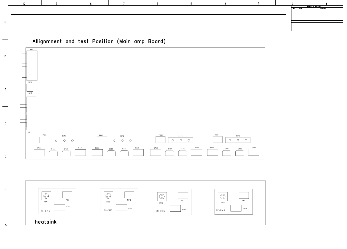
SERVICE PROCEDURE
ALIGNMENT PROCEDURES
1.MAIN AMP idling Adjustment
SET CONDITION
1) SEMI VOLUME POSITION at MAIN/SURROUND AMP Board
MAIN:VR71.VR74
SURROUND:VR72.VR73
NO Signal/No Load
AC Line Voltage:120V/60Hz.230V/50Hz
2) After turning on the unit keep it over than 25min (keep the power/Driver TR as normal temperature)
3) Adjust the voltage value of primary&secondary of wafer to be 25mV by rotating the semi volume of each channel
to the right
CHANNEL ADJUSTMENT MEASUREMENT VOLTAGE
FRONT-L CH VR-71 P801 23+/-2mV
FRONT-R CH VR-74 P804 23+/-2mV
SURROUNT-L CH VR-73 P803 23+/-2mV
SURROUNT-R CH VR-72 P802 23+/-2mV
4) CAUTION .
In case that power TR or DRIVER TR is needed to be replace for repairing the corresponding channel should be
adjusted again
FRONT AMP:Q433.Q435.Q437.Q439.Q330.Q332.Q334.Q336
SURROUND AMP:Q434.Q436.Q438.Q440.Q329.Q331.Q333.Q335
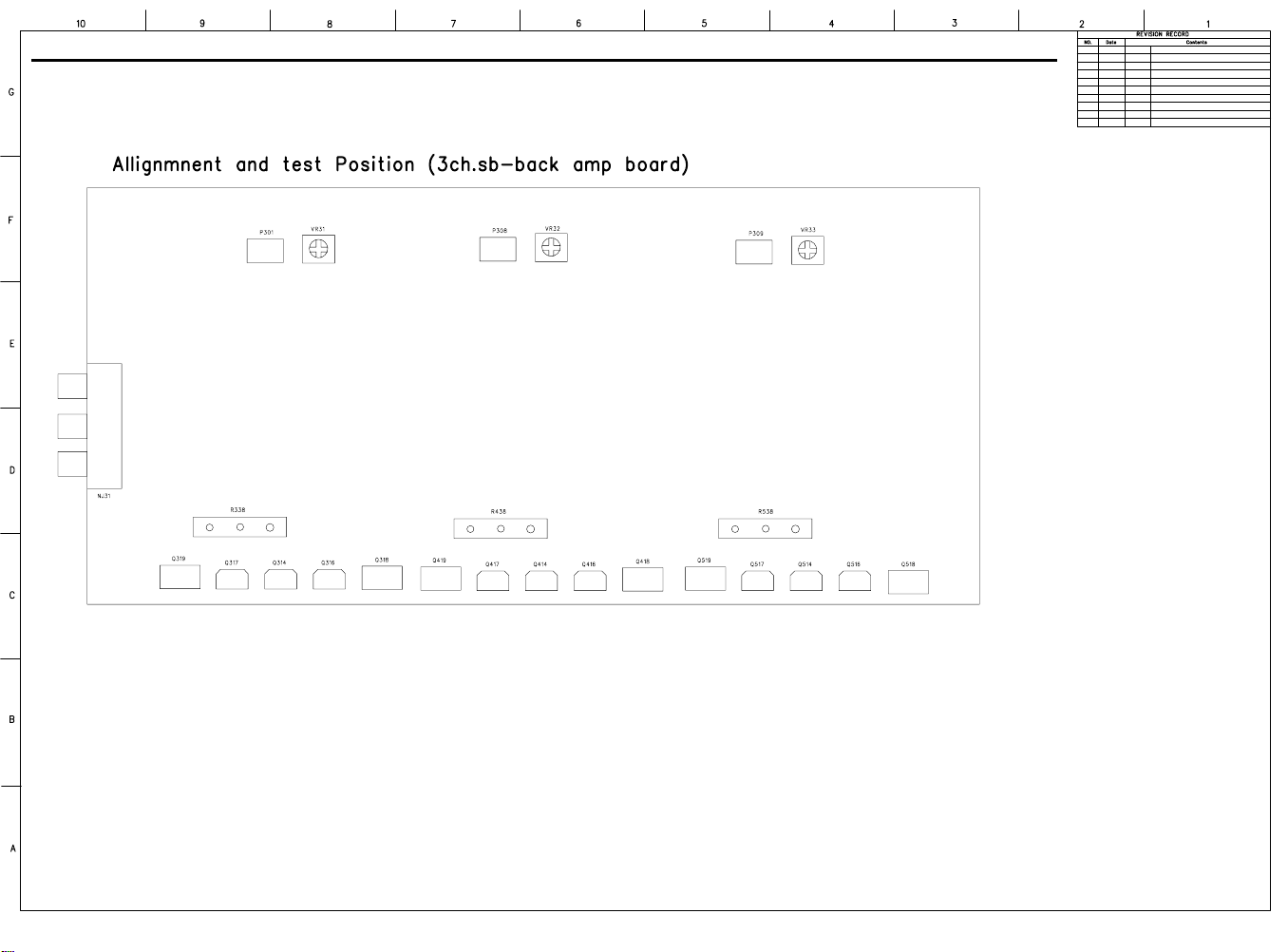
2.SURROUND BACK AMP idling Adjustment
SET CONDITION
1) SEMI VOLUME POSITION at CENTER/SURROUND BACK AMP Board
CENTER:VR32
SURROUND BACK:VR31.VR51
NO Signal/No Load
AC Line Voltage:120V/60Hz.230V/50Hz
2) After turning on the unit keep it over than 25min (keep the power/Driver TR as normal temperature)
3) Adjust the voltage value of primary&secondary of wafer to be 25mV by rotating the semi volume of each channel
to the right
CHANNEL ADJUSTMENT MEASUREMENT VOLTAGE
CENTER VR-32 P308 23+/-2mV
SUR BACK-L CH VR-31 P301 23+/-2mV
SUR BACK-R CH VR-51 P309 23+/-2mV
4) CAUTION .
In case that power TR or DVIER TR is needed to be replace for repairing the corresponding channel should be adjusted
again
CENTER AMP:Q416Q417.Q418.Q419
SUR BACK AMP:Q316.Q317.Q318.Q319.Q516.Q517.Q518.Q519
3.Cautions for main adjustment
1) At MAIN/SURROUND BACK BOARD.use the below capacitor after discharging for sufficent time for preventing possible
damage from electrical spark
MAIN C504.C505 AVR630 15000/63V
BOARD C571.C572 AVR430 12000/63V
SUR BACK C201.C202 AVR630 10000/63V
CENTER BOARD C201.C202 AVR430 8200/63V
2)The checking for MAIN/SURR-BACK BOARD should have the discharging circuit discharge
over 30sec.through(4R7Ohm 10W)resistor after push power sw off
AVR430/AVR630 harman/kardon
18
AVR430/AVR630 harman/kardon
19
20
AVR430/630 harman/kardon
harman/kardon Service Bulletin
Service bulletin # HK2004-04 October 2004
To: All harman/kardon Service Centers
Model: AVR430, AVR630
Subject: Rewiring Bias/Fan cables
In the event you receive an AVR430 or AVR630 with the complaint: “the unit intermittently goes in
standby or the fan runs constantly” perform the following modification. Please note other
component or connection failures can ca use the unit to go in to standby.
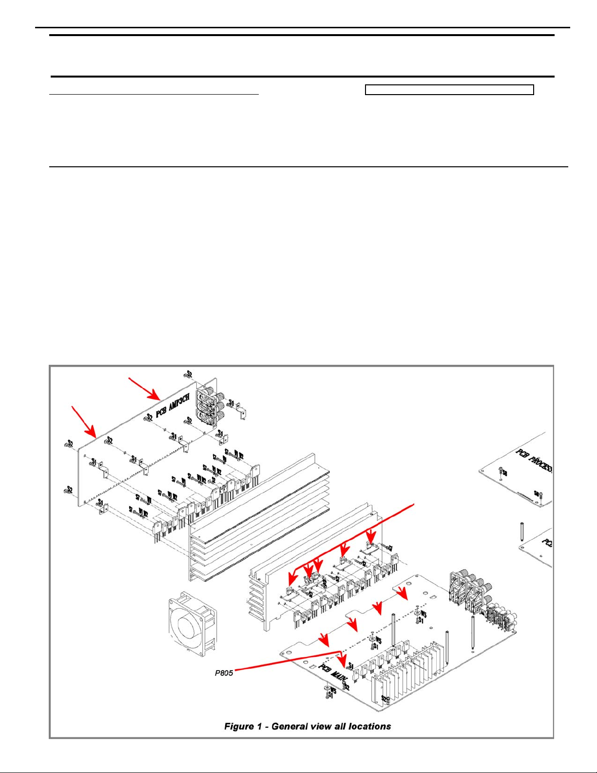
Synopsis: Hard wire Bias/Fan cables (7 cables, 12 connectors) from Bias PCB’s to main PCB, surround PCB.
Recheck all bias voltages.
1) Remove the top cover
2) Remove the DSP and Processor boards.
3) Locate and identify Bias cables connecting Bias and Surround PCB’s to main PCB:
MAIN PCB Location: P805, N801, N802, N803, N804
SURROUND PCB Location: N301, P307
BIAS PCB Location: P812, P813, P814, P815, P816
Warranty labor rate: MAJOR repair
21
AVR430/630 harman/kardon
4) Unplug each the cable on the Bias PCB, desolder the female plugs, cut the connectors off each wire,
strip the insulation 1/8” on each end and solder directly to the PCB assembly in each location.
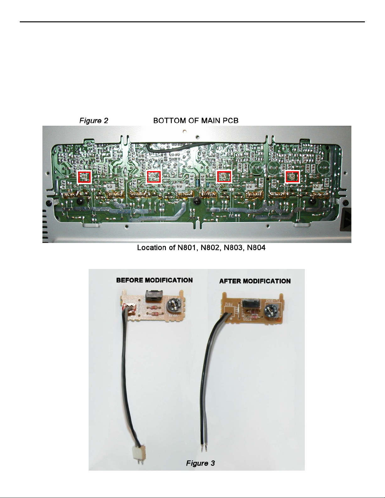
5) For locations N801, N802, N803, N804 on the Main PCB, set the unit on its side and remove the
bottom grille. (See Figure 2) Deso lder and remove each connector. Cut the connectors off each wire,
strip the insulation 1/8” on each end and solder directly to the PCB assembly in each location.
6) For location P805 (see Figure 1) on the Main PCB, unplug the cable, carefully cut away the female
plug with diagonal cutters on the PCB surface, leaving the three conductors intact. Cut the connector
off each wire, strip the insulation 1/8” on each end, slide a piece of shrink tubing on each conductor
and solder each wire directly to the three conductors on the PCB. Heat the shrink tubing to complete
the connection, and add some silicon seal or similar adherent to affix the wires on the PCB.
22
AVR430/630 harman/kardon
7) Replace the DSP and Processor boards
8) Recheck all bias voltages, following the instructions below:
MAIN AMP IDLE CURRENT ADJUSTMENT PROCEDURE
(Set variable resistors for MAIN/SURROUND Board)
Specialized equipment/parts needed:
Variable AC transformer (“Variac” type) to adjust and monitor AC line voltage.
Two pin harness plug to connect DMM to idle current test points, hk part# 55212910NR or equivalent
Conditions:
No Signal; No Load
AC Line Voltage adjust to: 120V/60Hz (120v model) or 230V/50Hz (230v model)
After turning the unit ON for 25 minutes or more to keep the Power/Driver TR at normal temperature,
adjust the DC voltage at the two pin connector to the specified value by rotating the variable resistors.
VR71-74 are located on the Bias PCB’s.
P801-804 are located on the main PCB just below the Bias PCB’s. To guide/seat the two pin harness plug
into the sockets, you may have to attach the harness wire to a long blade screwdriver as P801-803 are in
a deep recess.
CHANNEL ADJUSTMENT MEASUREMENT P OINT VOL TAGE
FRONT L CHAN VR71 P801 23mV ±2mV
FRONT R CHAN VR74 P804 23mV ±2mV
SURROUND L CHAN VR73 P803 23mV ± 2mV
SURROUND R CHAN VR72 P802 23mV ±2mV
SURROUND BACK A MP IDLE CURRENT ADJUSTMENT PROCEDURE
Same conditions as above.
After turning the unit ON for 25 minutes or more to keep the Power/Driver TR at normal temperature,
adjust the voltage value at the two pin connector to the specified value by rotating the variable resistors.
VR31,32,51 and P301,308,309 are located at the top edge of the Surround PCB
CHANNEL ADJUSTMENT MEASUREMENT POINT VOLTAGE
CENTER VR32 P308 23mV ±2mV
SURROND BACK L VR31 P 301 23mV ±2m V
SURROND BACK R VR51 P309 23mV ±2mV
9) After 5 minutes, check all voltages again at measurement points and re-adjust if necessary.
10) After more 5 minutes, check all voltages again at measurement points and re-adjust if necessary.
11) Replace the top cover and test the unit.
MODEL
AVR430
AVR430
AVR630
AVR630
SERIAL NUMBER (120V) SERIAL NUMBER (230V)
TF0001-01000
to
TF0001-08116
TF0007-08117 and above TF0007-06664 and above Modif ied by Factory None Required
TF0002-01000
to
TF0002-11138
TF0002-11139 and above TF0007-05651 and above Modif ied by Factory None Required
TF0006-01000
to
TF0006-06663
TF0007-01000
to
TF0007-05650
Unit may shut down or f an
Unit may shut down or f an
STATUS ACTION
Hard wire bias cables
may run conti nuously
Hard wire bias cables
may run conti nuously
to PCB’s
to PCB’s
23
AVR430/630 harman/kardon
harman/kardon TECH TIPS
Troubleshooting tips and solutions to common service problems
TIP# HKTT2004-03
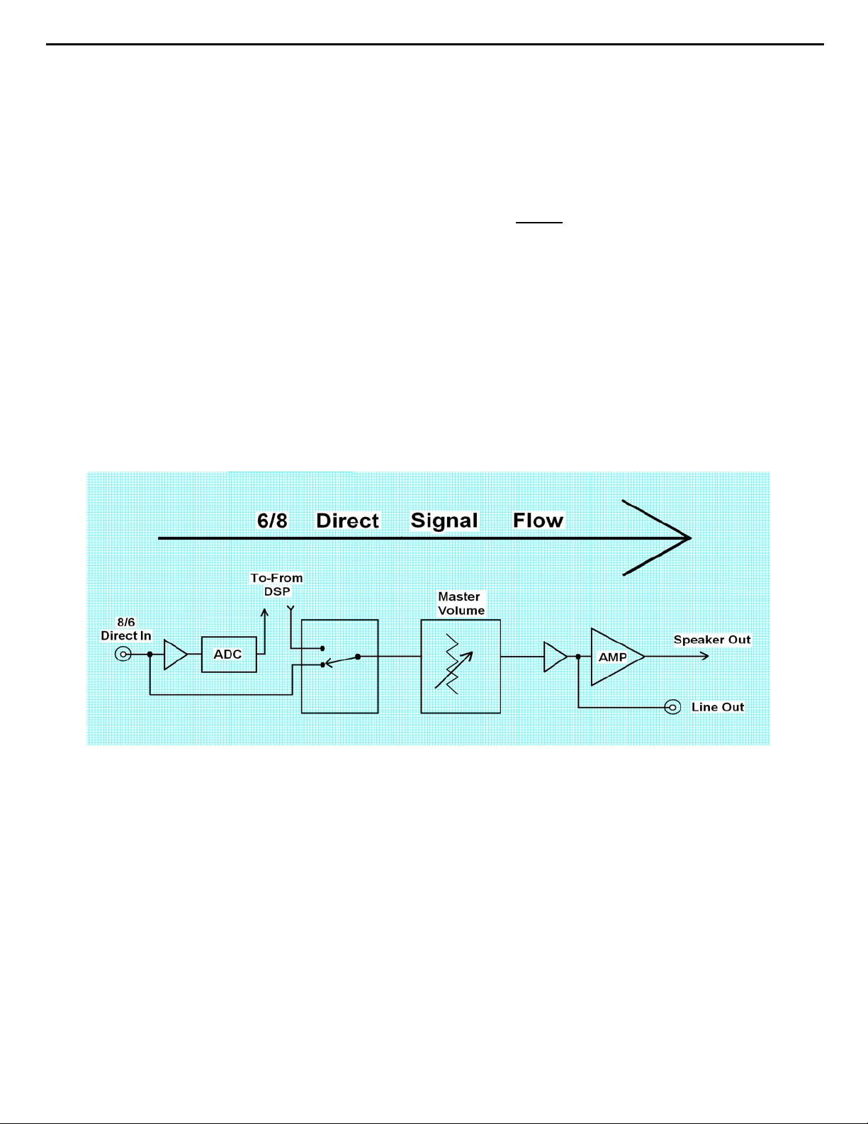
Isolating audio problems in an AVR receiver
Using 6/8 Direct In
The following charts are used to help the tech quickly isolate
audio problems in an AVR receiver. Use the following
procedures to help find what is working, then to quickly locate
the problem area.
Equipment needed:
9 1 set of (RCA) Y adaptors.
9 Function/signal generator.
9 Oscilloscope.
Procedure:
1) Do a factory reset of the receiver. (This will eliminate any common micro processor
problems.) Reset List can be found in this service manual.
2) Print the block diagram from the service manual.
3) With no inputs or speakers attached to the AVR turn on the receiver and turn the
volume all the way down.
4) Turn unit off.
5) Hook up an oscillator to the 6/8 Direct in jacks using the Y adaptors. Adjust the
oscillator to about 0db (.775Volts RMS).
6) Hook up an oscilloscope to monitor the line out jacks. Or, if there are no line out
(preamp out) jacks monitor the input to the power amps or the speaker outs.
(AVR125, 225, 130 do not have preamp out jacks)
7) Turn the AVR on. Select 6 or 8 direct in, depending on the receiver.
8) Slowly turn the volume control up until you can easily measure the voltage at the line
out jacks. ( -40 to -25db )
Models covered:
AVR210 AVR310
AVR220 AVR320
AVR520 AVR225
AVR125 AVR525
AVR130 AVR230
AVR330 AVR430
AVR630
Harman Consumer Group 250 Crossways Park Dr. Woodbury, New York 11797
Email Techsupport@harman.com
24
AVR430/630 harman/kardon
Isolating audio problems in an AVR receiver
Using 6/8 Direct In
9) At this point you will be able to check and assure all output levels are the same.
10) IF THE OUTPUT LEVELS ARE NOT THE SAME
you will need to use the charts to see where you are losing your signal. The chart
shows the analog signal flow from the input jacks to the output jacks.
11) If the output levels are the same check the power out stage at the speaker out jacks.
12) If you find the levels at the speaker out jacks are OK, your problem will be in the DSP
part of the receiver.
Congratulations! You have now eliminated 90% of the electronics in the AVR and
confirmed that the problem is in the DSP section.
STOP! Go no further. At this point
Harman Consumer Group 250 Crossways Park Dr. Woodbury, New York 11797
Email Techsupport@harman.com
25
AVR430/630 harman/kardon
Isolating audio problems in an AVR receiver
Using 6/8 Direct In
AVR,210,310,510
t
u
n
I
N
I
CH
6
FR 3 1 15 2 4 8 9 4 3 19 17 3 1 3
FL 5 7 13 27 25 21 20 25 26 10 12 5 7 1
SR 11 5 7 7 6 5 7 9
SL 9 24 22 22 23 3 1 7
C 5 21 19 19 20 3 1 5
SW 7 8 10 10 9 5 7 11
I
O
1
1
0
5
C
08
0
4
5
N
C
I
C
C
I
t
u
n
I
O
4
4
0
0
7
C7
C7
I
I
t
u
n
I
O
5
5
0
0
C7
C7
I
I
t
u
O
n
I
6
6
0
0
7
7
C
C
I
I
AVR220
t
u
n
O
I
N
I
CH
6
FR 5 7 15 2 4 8 9 4 3 5 7 10 12 5 7 1
FL 3 1 13 27 25 21 20 25 26 3 1 19 17 3 1 3
SR 11 5 7 7 6 5 7 9
SL 9 24 22 22 23 3 1 7
C 5 21 19 19 20 3 1 5
SW 7 8 10 10 9 5 7 11
1
0
5
C
I
8
1
0
0
4
5
C
C
CN
I
I
t
u
n
I
O
4
4
0
0
7
C7
C7
I
I
t
u
n
I
O
5
5
0
0
C7
C7
I
I
t
u
O
n
I
6
6
0
0
7
C
C7
I
I
t
u
n
O
I
5
5
0
0
7
7
C
C
I
I
t
u
n
I
O
4
4
1
1
7
C
C7
I
I
t
u
n
I
O
6
6
1
1
7
C7
C
I
I
t
u
n
O
I
5
5
0
0
7
7
C
C
I
I
t
u
n
I
O
7
7
1
6
1
1
1
7
7
C
C
I
I
t
u
n
I
O
6
1
1
7
C7
C
I
I
t
u
n
I
O
8
n
I
7
5
8
0
1
4
7
P
C
I
C
t
u
O
7
1
7
7
C
C
I
I
t
u
n
I
O
8
1
I
5
8
0
1
4
7
C
CP
AVR320/520
t
u
n
O
I
C
I
CN4
1
0
5
8
1
I
CP
8
1
0
0
4
5
C
C
CN
I
n
I
2
1
0
0
1
C1
C1
I
I
N
I
CH
8
FR 5 7 15 2 4 8 9 4 3 5 7 10 12 5 7 1
FL 3 1 13 27 25 21 20 25 26 3 1 19 17 3 1 3
SR 11 5 7 7 6 5 7 9
SL 9 24 22 22 23 3 1 7
C 5 21 19 19 20 3 1 5
SW 7 8 10 10 9 5 7 11
SBR 3 3 3 4 21 23 5 7
SBL 1 1 25 26 4 2 3 1
t
u
n
I
O
4
4
0
0
7
C7
C7
I
I
t
u
n
I
O
1
2
0
0
1
C1
c
i
I
t
u
n
I
O
5
5
0
0
C7
C7
I
I
UT
N
i
o
2
3
0
0
0
1
1
c
c
i
i
t
u
O
n
I
6
6
0
0
7
C
C7
I
I
t
u
O
3
t
u
n
I
O
4
4
1
1
7
C
C7
I
I
t
u
n
O
I
5
5
0
0
7
C
C
I
I
t
u
n
I
O
6
6
1
1
7
7
C7
C
I
I
t
u
n
I
7
1
C
I
n
O
I
7
1
7
C
I
O
8
8
1
1
7
7
C
I
AVR225/125
t
u
N
I
CH
6
L ch 27 25 19 20 5 7 1 3 1 9 10 1 2
R ch 24 22 22 23 3 1 3 5 7 15 14 4 5
SL 5476 579
SR 2 4 10 9 3 1 11
C 81843 31 7
SW 21 19 25 26 5 7 5
n
O
I
0
0
3
3
C
C
I
C
I
I
t
u
n
I
O
1
1
3
3
C
C
I
I
t
u
n
I
O
2
2
3
3
C
C
I
I
t
u
n
I
O
3
3
3
3
C
C
I
I
t
u
n
O
I
4
3
2
4
3
N1
C
I
C
I
B
t
u
n
O
I
1
1
8
8
C
C
I
I
t
u
n
I
O
0
0
8
8
N1
C
I
B
t
u
n
O
I
6
6
N1
B
t
u
5
0
4
CP
Harman Consumer Group 250 Crossways Park Dr. Woodbury, New York 11797
Email techsupport@harman.com
26
AVR430/630 harman/kardon
Isolating audio problems in an AVR receiver
Using 6/8 Direct In
AVR 525
t
t
k
c
a
J
n
I
FL 11 109 423 135 3 1 1 1
FR 3 3 21 22 21 23 5 7 28 6 6 7 3 3
SL 5524 43 3 1 5 5
SR 7 7 29 27 25 26 5 7 7 7
CTR 9957 76 3 1 9 9
SW 11 11 26 24 22 23 5 7 11 11
SBL 13 13 8 10 10 9 3 1 13 13
SBR 15 15 23 21 19 20 6 7 15 15
4
0
6
N4
P
u
n
I
O
C5
C5
I
I
t
u
n
O
I
C3
C3
I
I
u
n
n
O
I
9
C1
I
I
8
9
C1
C1
I
C2
I
I
t
u
n
I
O
0
n
I
0
C3
C2
I
C3
I
I
t
u
t
u
O
O
8
C2
C1
I
I
t
u
n
I
O
3
3
C2
C2
I
I
AVR130
t
n
n
i
h
c
6
L18172123 1
R191242 14
SL 24 22 21 23 9
SR 57 42 7
C27252123 5
SUB 2 4 4 2 3
SBL 21 19 21 23 5 7 13
SBR 8 10 4 2 3 1 11
I
3
2
C
I
n
I
u
u
O
O
6
2
3
2
C
I
6
2
C
I
C
I
t
t
n
u
I
O
2
4
2
C
I
C4
I
t
n
I
u
O
4
4
4
4
C
I
I
C
I
t
n
I
u
O
3
4
3
4
C
C
I
t
n
u
I
O
0
4
0
C
I
C4
I
t
n
I
9
4
C
I
C4
I
2
u
O
9
1
1
N1
N
B
B
t
u
n
O
I
5
5
C2
C2
I
I
t
u
n
I
O
4
4
C2
C2
I
I
t
u
n
I
O
6
6
C2
I
6
0
9
P
N8
AVR230/330
t
n
n
i
h
c
6
L18172123 1
R191242 14
SL 24 22 21 23 9
SR 57 42 7
C27252123 5
SUB 2 4 4 2 3
SBL 21 19 21 23 5 7 13
SBR 8 10 4 2 3 1 11
I
3
2
C
I
n
I
u
u
O
O
6
2
3
2
C
I
6
2
C
I
C
I
t
t
n
u
I
O
2
4
2
C
I
C4
I
t
n
I
u
O
4
4
4
4
C
I
I
C
I
t
n
I
u
O
3
4
3
4
C
C
I
t
n
u
I
O
0
4
0
C
I
C4
I
t
n
I
9
4
C
I
C4
I
2
u
O
9
1
1
N1
N
B
B
AVR630/430
t
n
I
CH
8
FL 11012109316931423131
FR 319171920 5 72320 5 7 2123 5 7 26 7
SL 52443 31
SR 727252526 5 7
CTR 95776 3 1
SW 11 24 22 22 23 5 7
SBL 13 8 10 10 9 3 1
SBR 15 21 19 19 20 5 7
4
0
N4
4
0
N4
u
O
3
3
C
C
C
I
I
I
t
u
n
I
O
5
5
C1
C
C
I
I
I
t
u
n
I
O
4
4
1
1
C
C
I
I
t
u
n
O
I
9
9
1
C
C
I
I
t
t
u
n
O
I
2
2
1
1
C
I
n
O
I
5
5
2
2
C
I
u
n
I
O
3
3
C
I
t
u
C
I
C
C
I
I
t
u
n
I
O
4
4
2
2
C
C
I
I
t
u
n
I
O
7
7
2
2
C
C
I
I
t
u
n
O
I
6
6
2
2
C
I
t
u
n
O
I
8
8
1
1
C
C
I
I
t
u
n
I
O
0
0
2
2
C
C
I
I
t
u
n
I
O
3
3
C
I
Harman Consumer Group 250 Crossways Park Dr. Woodbury, New York 11797
Email techsupport@harman.com
27
AVR430/630 harman/kardon
harman/kardon TECH TIPS
Troubleshooting tips and solutions to common service problems
For models:
AVR7000/7200/7300/8000
AVR100/200/300/500
AVR110/210/310/510
AVR120/220/320/520
AVR125/225/325/525
AVR130/230/330/430/630
AVR135/235/335/435/635
AVR10
DPR1001
DPR1005
DPR2005
HK3370/3470/3375/3475
HK3250
Subject: Backup Memory on AVR/DPR/HK series receivers
In the event of the complaint: “the receiver is losing its memory (any programmed syst em settings)
when the unit is turned off, or after the unit is unplugged (briefly*)”:
Check and replace:
Model Designator Location Description Part number
AVR10
AVR7000 C730 Front PCB 0.047 Farad 5.5v capacitor
AVR7200 C106 Front PCB 0.047 Farad 5.5v capacitor # P10790-ND
AVR7300 C657 DSP PCB 0.047 Farad 5.5v capacitor # H01-CEZXA0479MN-5
AVR8000 C726 Front PCB 0.047 Farad 5.5v capacitor
AVR100/200 C412 Front PCB 0.047 Farad 5.5v capacitor # CEGT-B473J-0J0
AVR300 C906 Front PCB 0.1Farad 5.5v capacitor
AVR500 C906 Front PCB 0.1Farad 5.5v capacitor
AVR110/210/310/510
AVR120/220/320/520
AVR125/225 C734,C885 Front PCB two 0.1F capacitors in parallel # BCESOHD104
AVR325/525 C106 Front PCB 0.047 Farad 5.5v capacitor # P10790-ND
AVR130/230/330 BAT1 Front PCB 3.6v Battery # HABGP40BVH3A3H
AVR135/235/335 BAT1 Front PCB 3.6v Battery # HGP15BNH3A3H
AVR430/630 C657 DSP PCB 0.047 Farad 5.5v capacitor # CEZXA0479MN-5
AVR435/635 C557 DSP PCB 0.047 Farad 5.5v capacitor # H03-CEZXA0479MN-0
DPR1001 BC601 Main PCB 0.1Farad 5.5v capacitor # CEGT-B104J-0J0
DPR1005/2005 C437
HK3370/3470 C301 Front PCB 0.1Farad 5.5v capacitor # CEGT-B104J-0J0
HK3375/3475 C301 Front PCB 0.1Farad 5.5v capacitor # CEGT-B104J-0J0
HK3250
* After approximately two weeks of bei ng disconnected fr om AC supply, even a norm ally functioning receiver may
lose any program med settings and switch to default settings. (Four weeks for the DPR1005 & 2005)
C712
D709
C216 Front PCB 0.047 Farad 5.5v capacitor # P10790-ND
C712
D709
Front PCB
Processor
PCB
Front PCB
0.047 Farad 5.5v capacitor
and 1N4148 diode
0.047 Farad 5.5v capacitor # CEZXA0479MN-5
0.047 Farad 5.5v capacitor
and 1N4148 diode
TIP# HKTT2003-01 Rev5
#3439247315
#2058322101
# P10790-ND or
# J3432147324X
# 55230310NR or
# P10790-ND
# J4433210421X
or # P10791-ND
# J4433210421X
or # P10791-ND
#3439247315
#2058322101
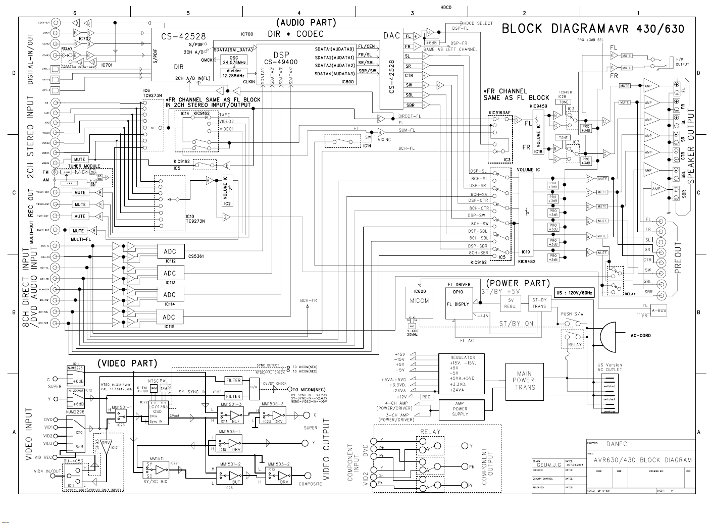
28
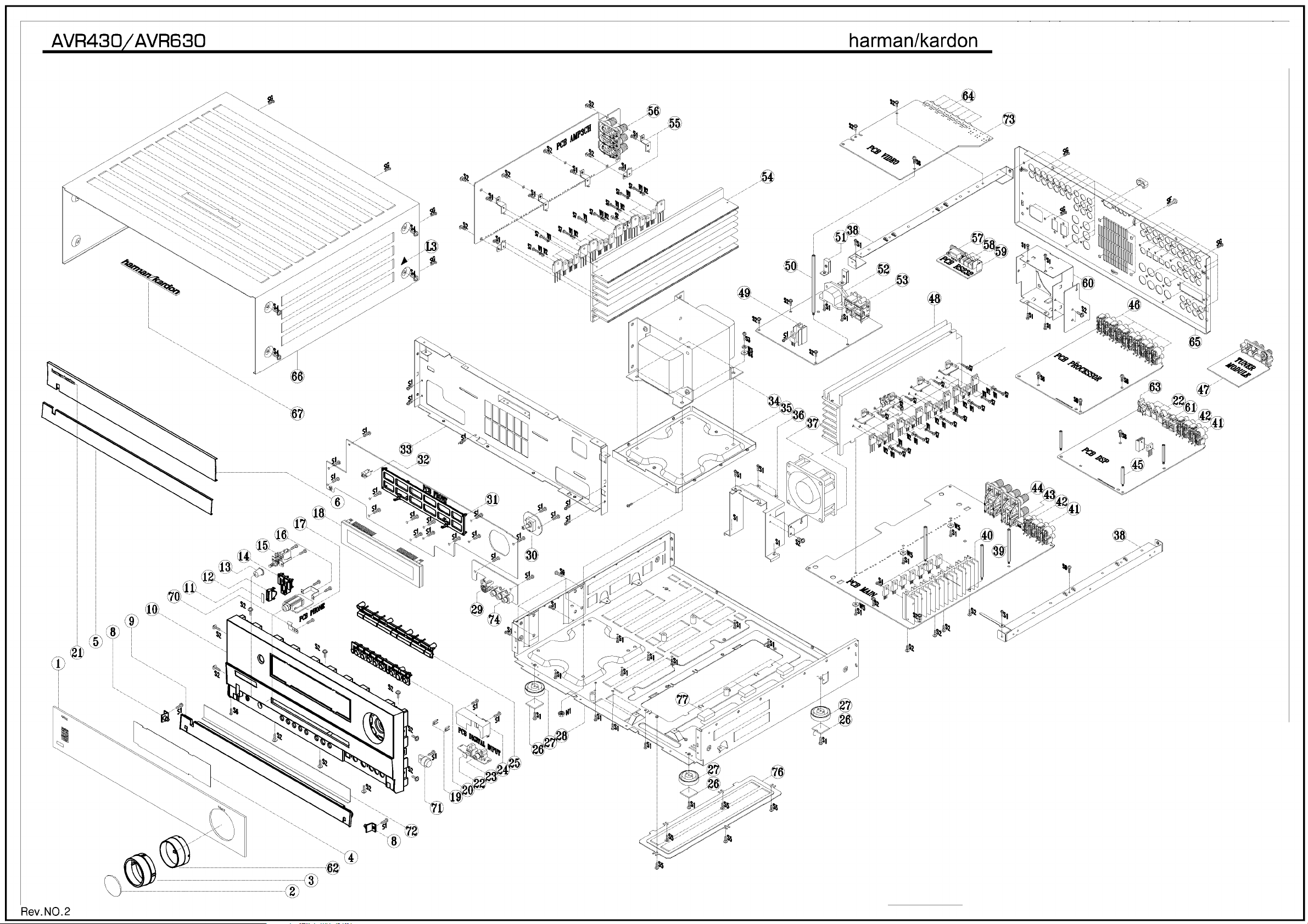
29

y
30
AVR430/630 harman/kardon
AVR430/630 EXPLODED VIEW PARTS LIST
Ref# Description Part Number Qt
1 WINDOW DISPLAY AVR630 H01-ZPC1119GABT-A 1
WINDOW DISPLAY AVR430 H01-ZPC1022GABT-3 1
2 CAP KNOB VOLUME AVR630 H01-ZPC1020GACR-2 1
3 COVER KNOB VOLUME AVR430/630 H01-ZPC1021GASG-4 1
4 FILTER DISPLAY AVR430/630 H01-ZPC1018GART-7 1
5 AL DOOR AVR430/630 H01-ZMC11S00200-0 1
6 AL PANEL AVR430/630 H01-ZMC11S00300-2 1
7 Not Used
8 BKT HINGE AVR430/630 H01-ZMC11S04A00-1 2
9 DOOR AVR430/630 ZPC1002GAGY-9 1
10 PANEL FRONT AVR430/630 ZPC1101GBGY-5 1
11 CAP BUTTON STAND-BY AVR430/630 H01-ZMC11S12A00-8 1
12 INDICATOR STAND-BY ZPC1007GAMW-9 1
13 BUTTON POWER ZPC1003GAGY-5 1
14 BUTTON STANDBY ZPC1006GAWH-0 1
15 SW PUSH POWER SDDLB15700 H01-SWA2B221PDAA-7 1
16 BKT HEADPHONE H01-ZMB01S00100-5 1
17 JACK PHONE 6.35 H70980110S 9P BK H01-SOSS9CKX3NN-9 1
18 FL HCA-18LL03 H01-VDHCA18LL03-7 3
19 INDICATOR VIDEO ZPC1102GAMW-1 2
20 BUTTON 8 KEY ZPC1005GAGY-8 1
21 BADGE AL HARMAN/KARDON SILVER H01-ZMC12S20A00-2 1
22 IC-REMOTE TORX179 FIBER OPTIC RECEIVER SHUTTER TYPE n/a 4
23 JACK RCA 1P JE010003MN GND OR H01-SORA1JE01NN-0 1
24 AC PUN SHIELD DIGITAL ET H01-ZMC12S17A00-0 1
25 BUTTON 7 KEY H01-ZPC1004GASG-0 1
26 RUBBER FOOT 19.7X19.7X2T BK ZFNR19720SB-5 4
27 FOOT 50MM 15.8MM ZPC1103GAGY-A 4
28 CHASSIS MAIN AVR430/630 n/a 1
29 CON DIN SCKT SOCKET CONNECTOR SVHS EST-S408J H01-SORA8OSC5N8-2 1
30 SWIROT EC16B24204 5V 500U0A 10T 3P 0 0 H01-SWE3A0505S1-9 1
31 HOLDER VFD AVR430/630 ZPC1017GABK-6 1
32 IC-REMOTE RPM6938-RSIP-A3 RECEIVER 38KHZ- H01-ICRPM6938NN-3 1
33 CHASSIS FRONT AVR430/630- n/a 1
34 MN X'FORMER AVR630 120V- H01-TXPWMM630B0-4 1
35 BKT TRANS BOTTOM- H01-ZMC12S08B00-5 1
36 BKT FAN FRONT AVR430/630- H01-ZMC11S09A00-6 1
37 FAN JF0925S1L H01-ZVC11FAN100-6 1
38 BKT FRAME GUIDE H01-ZMC11S04B00-3 2
39 STANDOFF HEX M4X0.7 6X61.9H ZMC12S14AYE-9 3
40 H/SINK REG 118*20* n/a 1
41 CON PHONO SCKT RCA 4P JW-4104RSA H01-SORA40RSANN-6 1
42 CON PHONO SCKT RCA 4P JW-4104RSC H01-SORA40GNDNN-7 1
43 JACK-TELE SNAP-IN GOLDEN TELECOM GDL1-8P8C 8T BK 0 0 n/a 1
44 CONN-SPE TERMINAL SPKR 8P SH081136JP FE 19MM 8 -- 0 0- H01-SOPA81900NN-8 1
45 STANDOFF HEX M4X0.7 6X31.9H ZMC12S13AYE-1 3
46 CON PHONO SCKT RCA 4P JW4104RS GND H01-SORA40RSANN-6 5
47 TUNER MODULE KST-MB011MW0-80 US H01-ZVC11TUNE01-7 1
48 H/SINK MAIN AVR630 n/a 1
49 AC HEATSINK 17*15*30 AVR430/630 – ME- n/a 1
50 STANDOFF HEX M4X0.7 6X111.2H ZMC12S15AYE-6 1
51 BKT INLET H01-ZMC12S19A00-2 2
52 CON MAINS INLET A/C INLET 7014-NGP H01-SOXA27014NN-9 1
53 CONN-SPE AC OUTLET 2P 110V FE 12.75MM 2 BK 0 0 H01-SOPA21275BK-3 1
54 H/SINK AMP AVR630 n/a 1
H/SINK AMP AVR430 n/a 1
55 BKT HEATSINK n/a 6
56 CONN-SPE TERMINAL SPKR 6P SH0611708P FE 19MM 6 BK 0 0 H01-SOPA619BKNN-7 1
57 JACK D-SUB 9P 87204-6063 W/DUST COVER BK SOPA96063NN-0 1
 Loading...