


AVR 3600

AVR 3600
AUDIO/VIDEO RECEIVER
OWNER’S M ANUAL

IMPORTANT SAFETY INSTRUCTIONS
1. Read these instructions.
2. Keep these instructions.
3. Heed all warnings.
4. Follow all instructions.
5. Do not use this apparatus near water.
6. The A/V receiver’s cabinet may be cleaned by gently wiping with a soft
cotton or microfiber cloth. Do not use water or any liquid cleaners.
7. Do not block any of the ventilation openings. Install in accordance with
the manufacturer’s instructions.
8. Do not install near any heat sources such as radiators, heat registers,
stoves or other apparatus (including amplifiers) that produce heat.
9. Do not defeat the safety purpose of the polarized or grounding-type
plug. A polarized plug has two blades with one wider than the other.
A grounding-type plug has two blades and a third grounding prong.
The wide blade or the third prong is provided for your safety. When the
provided plug does not fit into your outlet, consult an electrician for
replacement of the obsolete outlet.
10. Protect the power cord from being walked on or pinched, particularly
at plugs, convenience receptacles and the point where they exit from
the apparatus.
11. Only use the attachments/accessories specified by the manufacturer.
12. Use only with a cart, stand, tripod, bracket or table specified by the
manufacturer, or sold with the apparatus. When a cart is used, use
caution when moving the cart/apparatus combination to avoid injury
from tip-over.
13. Unplug this apparatus during lightning storms or when unused for long
periods of time.
14. Refer all servicing to qualified service personnel. Servicing
is required when the apparatus has been damaged in any
way, such as power supply cord or plug is damaged, liquid
has been spilled or objects have fallen into the apparatus,
the apparatus has been exposed to rain or moisture, does not operate
normally, or has been dropped.
Wet Location Marking
Apparatus shall not be exposed to dripping or splashing and no objects
filled with liquids, such as vases, shall be placed on the apparatus.
Service Instructions
CAUTION – These servicing instructions are for use by qualified service
personnel only. To reduce the risk of electric shock, do not perform any
servicing other than that contained in the operating instructions, unless
you are qualified to do so.
Outdoor Use Marking
WARNING – To reduce the risk of fire or electric shock, do not expose this
apparatus to rain or moisture.
2
SAFETY INFORMATION

3
SAFETY INFORMATION
IMPORTANT SAFETY INFORMATION
Verify Line Voltage Before Use
Your AVR 3600 has been designed for use with 120-volt AC current.
Connection to a line voltage other than that for which it is intended can
create a safety and fire hazard and may damage the unit.
If you have any questions about the voltage requirements for your specific
model, or about the line voltage in your area, contact your selling dealer
before plugging the unit into a wall outlet.
Do Not Use Extension Cords
To avoid safety hazards, use only the power cord supplied with your unit.
We do not recommend that extension cords be used with this product. As
with all electrical devices, do not run power cords under rugs or carpets or
place heavy objects on them. Damaged power cords should be replaced
immediately by an authorized service center with a cord meeting factory
specifications.
Handle the AC Power Cord Gently
When disconnecting the power cord from an AC outlet, always pull the
plug; never pull the cord. If you do not intend to use the unit for any
considerable length of time, disconnect the plug from the AC outlet.
Do Not Open the Cabinet
There are no user-serviceable components inside this product. Opening the
cabinet may present a shock hazard, and any modification to the product
will void your warranty. If water or any metal object such as a paper clip,
wire or staple accidentally falls inside the unit, disconnect it from the AC
power source immediately, and consult an authorized service center.
CATV or Antenna Grounding
If an outside antenna or cable system is connected to this product, be
certain that it is grounded so as to provide some protection against voltage
surges and static charges. Section 810 of the National Electrical Code,
ANSI/NFPA No. 70-1984, provides information with respect to proper
grounding of the mast and supporting structure, grounding of the lead-in
wire to an antenna discharge unit, size of grounding conductors, location
of antenna discharge unit, connection to grounding electrodes and require-
ments of the grounding electrode.
NOTE TO CATV SYSTEM INSTALLER: This reminder is provided
to call the CATV (cable TV) system installer’s attention to article 820-40 of
the NEC, which provides guidelines for proper grounding and, in particular,
specifies that the cable ground shall be connected to the grounding system
of the building, as close to the point of cable entry as possible.
Installation Location
• To ensure proper operation and to avoid the potential for safety hazards,
place the unit on a firm and level surface. When placing the unit on a
shelf, be certain that the shelf and any mounting hardware can support
the weight of the product.
• Make certain that proper space is provided both above and below the
unit for ventilation. If this product will be installed in a cabinet or other
enclosed area, make certain that there is sufficient air movement within
the cabinet. Under some circumstances, a fan may be required.
• Do not place the unit directly on a carpeted surface.
• Avoid installation in extremely hot or cold locations, or in an area that is
exposed to direct sunlight or heating equipment.
• Avoid moist or humid locations.
• Do not obstruct the ventilation slots on the top of the unit, or place
objects directly over them.
• Due to the weight of the AVR 3600 and the heat generated by the ampli-
fiers, there is the remote possibility that the rubber padding on the bot-
tom of the unit’s feet may leave marks on certain wood or veneer materi-
als. Use caution when placing the unit on soft woods or other materials
that may be damaged by heat or heavy objects. Some surface finishes
may be particularly sensitive to absorbing such marks, due to
a variety of factors beyond our control, including the nature of the finish,
cleaning materials used, and normal heat and vibration caused by the
use of the product, or other factors. We recommend that caution be exer-
cised in choosing an installation location for the component and in normal
maintenance practices, as your warranty will not cover this type of damage
to furniture.
Cleaning
When the unit gets dirty, wipe it with a clean, soft, dry cloth. If necessary,
and only after unplugging the AC power cord, wipe it with a soft cloth
dampened with mild soapy water, then a fresh cloth with clean water. Wipe
it dry immediately with a dry cloth. NEVER use benzene, aerosol cleaners,
thinner, alcohol or any other volatile cleaning agent. Do not use abrasive
cleaners, as they may damage the finish of metal parts. Avoid spraying
insecticide near the unit.
Moving the Unit
Before moving the unit, be certain to disconnect any interconnection cords
with other components, and make certain that you disconnect the unit from
the AC outlet.
Important Information for the User
This equipment has been tested and found to comply with the limits for a
Class-B digital device, pursuant to Part 15 of the FCC Rules. The limits are
designed to provide reasonable protection against harmful interference in
a residential installation. This equipment generates, uses and can radiate
radio-frequency energy and, if not installed and used in accordance with
the instructions, may cause harmful interference to radio communication.
However, there is no guarantee that harmful interference will not occur in
a particular installation. If this equipment does cause harmful interference
to radio or television reception, which can be determined by turning the
equipment off and on, the user is encouraged to try to correct the interfer-
ence by one or more of the following measures:
• Reorient or relocate the receiving antenna.
• Increase the separation between the equipment and receiver.
• Connect the equipment into an outlet on a circuit different from that to
which the receiver is connected.
• Consult the dealer or an experienced radio/TV technician for help.
This device complies with Part 15 of the FCC Rules. Operation is subject to
the following two conditions: (1) this device may not cause harmful inter-
ference, and (2) this device must accept interference received, including
interference that may cause undesired operation.
NOTE: Changes or modifications may cause this unit to fail to comply with
Part 15 of the FCC Rules and may void the user’s authority to operate the
equipment.
UNPACKING
The carton and shipping materials used to protect your new receiver during
shipment were specially designed to cushion it from shock and vibration.
We suggest that you save the carton and packing materials for use in ship-
ping if you move, or should the unit ever need repair.
To minimize the size of the carton in storage, you may wish to flatten it.
This is done by carefully slitting the tape seams on the bottom and collaps-
ing the carton. Other cardboard inserts may be stored in the same manner.
Packing materials that cannot be collapsed should be saved along with the
carton in a plastic bag.
If you do not wish to save the packaging materials, please note that the
carton and other sections of the shipping protection are recyclable. Please
respect the environment and discard those materials at a local recycling
center.
It is important that you remove the protective plastic film from the front-
panel lens. Leaving the film in place will affect the performance of your
remote control.
4
TABLE OF CONTENTS
2 SAFETY INFORMATION
5 INTRODUCTION
7 FRONT- PANEL CONTROLS
9 REAR - PANEL CONNECTIONS
11 MAIN REMOTE CONTROL
FUNCTIONS
15 ZONE 2 REMOTE CONTROL
FUNCTIONS
17 INTRODUCTION TO HOME THEATER
18 CONNECTIONS
18 Speaker Connections
18 Subwoofer
18 Connecting Source Devices to the AVR
18 Audio Connections
18 Digital Audio
19 Analog Audio
19 Video Connections
19 Digital Video
19 Analog Video
20 Antennas
20 RS-232 Serial Port
21 SPEAKER PLACEMENT
22 GE T TING STARTED
24 INSTALLATION
24 Step One – Connect Source Devices
24 Step Two – Connect TV
24 Step Three – Connect Loudspeakers
24 Step Four – Connect
24 Step Five – Connect FM Antenna
24 Step Six – Connect AM Antenna
24 Step Seven – Connect SIRIUS Antenna Module
29 INITIAL SETUP
29 Using the On-Screen Menu System
29 Configure the AVR 3600 Using EzSet/EQ
™
Technology
29 Set Up Sources
33 OPERATION
33 Turning On the AVR 3600
33 Volume Control
33 Dolby Volume
33 Mute Function
34 Sleep Timer
34 Audio Effects
34 Video Modes
34 Headphones
34 Source Selection
34 Using the Tuner
35 SIRIUS
®
Radio Operation
35 USB Playback
36 Internet Radio
37 Network Playback
37 Recording
37 Using Docking Station
38 Selecting a Surround Mode
40 ADVANCED FUNCTIONS
40 Audio Processing and Surround Sound
40 Analog Audio Signals
40 Digital Audio Signals
40 Surround Modes
41 Dolby
®
Surround Settings
42 Manual Speaker Setup
45 Audio Effects
45 Video Adjustments
45 Video Modes
46 How to Adjust the Custom Picture Settings
47 Multizone Operation
47 Operating the Multizone System
48 System Settings
49 Advanced Remote Control Functions
51 Processor Reset
51 Memory
52 TROUBLESHOOTING GUIDE
53 APPENDIX
67 Trademark Acknowledgments
67 TECHNICAL SPECIFICATIONS
WARNING
For Canadian model
Modèle pour les Canadien
Cet appareil numérique de la classe B est
conforme à la norme NMB-003 du Canada.
Sur les modèles dont la fiche est polarisee:
ATTENTION: Pour éviter les chocs électriques,
introduire la lame la plus large de la fiche
dans la borne correspondante de la prise et
pousser jusqu’au fond.
This Class B digital apparatus complies with
Canadian ICES-003. For models having a
power cord with a polarized plug:
CAUTION: To prevent electric shock, match
wide blade of plug to wide slot, fully insert.
To prevent fire or shock hazard, do not
expose this appliance to rain or moisture.
FPO

5
INTRODUCTION
Please register your AVR 3600 at
www.harmankardon.com.
NOTE: You’ll need the product’s serial number. At the same
time, you can choose to be notified about new products and/or
special promotions.
Thank you for choosing a Harman Kardon
®
product!
For more than fifty years, the Harman Kardon
®
mission has been to
share a passion for music and entertainment, using leading-edge
technology to achieve premium performance. Harman Kardon, Inc.,
invented the receiver, a single component designed to simplify
home entertainment without compromising performance. Over
the years, Harman Kardon products have become easier to use,
while offering more features and sounding better than ever.The
AVR 3600 multizone 7.1-channel digital audio/video receiver contin-
ues this tradition with some of the most advanced audio and video
processing capabilities yet, and a wealth of listening and viewing
options.
To obtain the maximum enjoyment from your new receiver, please
read this manual and refer back to it as you become more familiar
with its features and their operation.
If you have any questions about this product, its installation or its
operation, please contact your Harman Kardon retailer or custom
installer, or visit the Web site at www.harmankardon.com.
Harman Kardon AVR 3600 7.1-Channel
Audio/Video Receiver
Audio Section
• 85 Watts x 7, seven channels driven at full power at 8 ohms,
20Hz – 20kHz, <0.07% THD, 595 watts total
• High-current capability, ultrawide-bandwidth amplifier design with
low negative feedback
• All-discrete amplifier circuitry
• Quadruple-crossover bass management with DVD-Audio bass
management capability
• Dual 24-bit, twin-core Texas Instruments DA 710 DSP processors
• 192kHz/24-bit A/D and D/A conversion
• Sampling upconversion to 96kHz
• Dolby
®
Volume processing
Surround Modes
• Dolby Digital EX, Dolby Digital Plus, Dolby TrueHD
• Dolby Pro Logic
®
II and IIx (Movie, Music and Game), up to 96kHz
• Harman Virtual Speaker
• Harman Headphone
• DTS-HD High Resolution Audio
™
, DTS-HD Master Audio
™
• DTS
®
(5.1; DTS Stereo; DTS-ES
®
6.1 Discrete and Matrix)
• DTS 96/24
™
(DTS Stereo)
• DTS Neo:6
®
(Cinema 5,-6 or 7-channel; Music 5, -6 or
7-channel), up to 96kHz
• Logic 7
®
(Movie, Music and Game), up to 96kHz
• 5- or 7-Channel Stereo, up to 96kHz
• Surround Off (DSP or Analog Bypass)
6
INTRODUCTION
Audio Inputs
• AM/FM/SIRIUS
®
* tuner
• Analog Audio 1 through 5
• Front-panel Analog Audio
• 6-/8-Channel Analog Audio
Audio/Video Inputs
• Three Analog Video
• Front-panel Analog Video
• Two Component Video 100MHz
• Four HDMI
™
(V.1.3a with Deep Color)
• Faroudja DCDi Cinema
™
video processing
Transcodes composite video to component video
Transcodes 480i video to component video format, with
upscaling to 1080i
Transcodes 480i video to HDMI output, with upscaling
to 1080p
• dock for iPod** and iPone connectivity with
audio/video playback
Digital Audio Inputs
• Coaxial: two rear-panel/one front-panel
• Optical: three rear-panel/one front-panel
Outputs
• 7.1-Channel preamp outputs
• Analog Audio 2 and 4
• Analog Video 2
• Video Monitor (composite and component)
• Digital Audio (one coaxial)
• HDMI (V.1.3a with Deep Color)
• Multizone Audio: speaker- level and two line-level (one
dedicated, one shared with surround back channels)
• A-BUS
®
port
• Headphone
Ease of Use
• EzSet/EQ
™
automated setup (microphone supplied)
• Full-color user interface and setup menu, generated in
high-definition video
• Two-line dot-matrix front-panel display
• Color-coded connections
• Programmable, learning seven-device main remote control
(includes AVR control over The Bridge III)
• Source input renaming
• Lip Sync Delay (up to 180msec)
• USB port for system upgrades
• Switched accessory power outlet
• Remote infrared (IR) input and output
• Zone 2 IR input, Carrier IR Output and A-BUS IR Output
• IEC detachable AC power cord for easy installation
Supplied Accessories
The following accessory items are supplied with the AVR 3600.
If any of these items are missing, please contact Harman Kardon
customer service at www.harmankardon.com.
• System and Zone 2 remote controls
• EzSet/EQ microphone
• docking station for iPod and iPhone
• AM loop antenna
• FM wire antenna
• Six AAA batteries
• Two covers for front-panel jacks
• AC power cord
*
SIRIUS Satellite Radio tuner and subscription to SIRIUS service required.
Hardware and service sold separately. SIRIUS service is not available in
Alaska or Hawaii.
**
Charges iPod nano 4th generation, iPod Touch 2nd generation, iPhone 3G,
iPod nano 3rd generation, iPod classic, iPhone, iPod Touch 1st generation,
iPod nano 2nd generation, iPod 5th generation, iPod nano 1st generation,
iPod 4th generation, iPod mini.
7
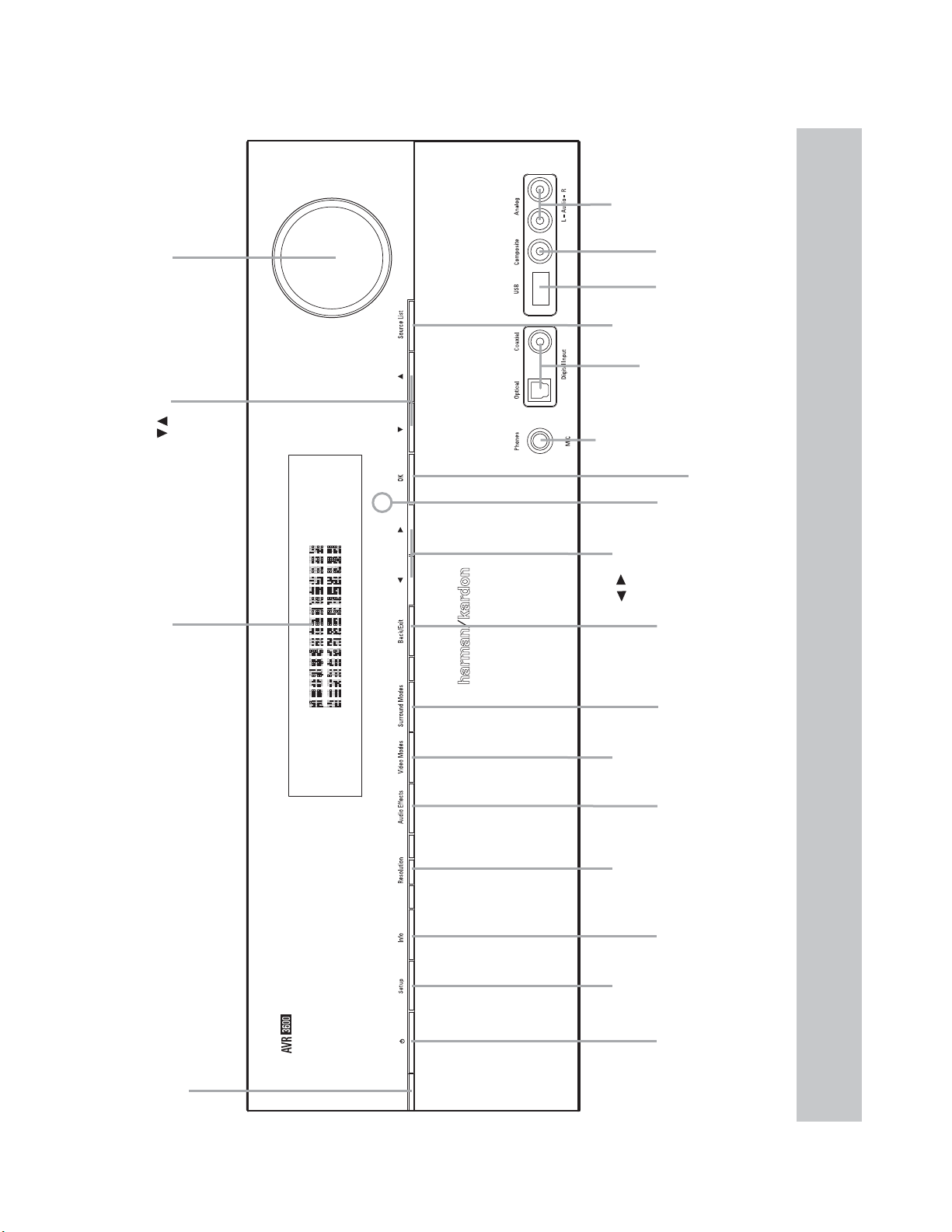
FRONT- PANEL CONTROLS
Resolution Navigation
Video
Modes
Source List
Back/Exit
OK
Navigation
Headphone
Jack/EzSet/EQ
Microphone
Input
Digital
Audio Inputs
(Optical and
Coaxial Front)
Remote
IR Sensor
USB
Port
Video
Front Input
Analog Audio
Front Inputs
Surround
Modes
Audio
Effects
Setup
Standby/On
Switch
Info
Settings
Volume
Message DisplayPower
Indicator
/
/
NOTE: To make it easier to follow the instructions throughout the manual that refer to this illustration, a copy of this page may be downloaded from the Product
Support section at www.harmankardon.com.

8
FRONT- PANEL CONTROLS
Power Indicator: This LED has three possible modes:
• Main Power Off: When the AVR is unplugged or the rear-
panel Main Power Switch is off, this LED is off.
• Standby: Amber indicates that the AVR is ready to be turned on.
• On: When the AVR is turned on, this LED turns white.
NOTE: If the PROTECT message ever appears, turn off the
AVR and unplug it. Check all speaker wires for a possible short.
If none is found, bring the unit to an authorized Harman Kardon
service center for inspection and repair before using it again.
Standby/On Switch: This electrical switch turns the
receiver on, or places it in Standby mode for quick turn-on.
Setup Button: Press this button to access the AVR’s main
menu.
Info Settings Button: Press this button to directly access
the AVR’s Source Info submenu, which contains the settings for the
current source.
Resolution: Press this button to access the AVR’s video output
resolution setting: 480i, 480p, 720p, 1080i, 1080p or 1080p/24 (if
available on source and display).
IMPORTANT NOTE: If the AVR’s video output resolution
is set higher than the capabilities of the actual connection,
you will not see a picture. If the best available video connection
from the AVR to the TV is composite video, press this button
and change the resolution to 480i.
Audio Effects: Press this button to directly access the Audio
Effects submenu, which allows adjustment of the tone and other
audio controls. See the Initial Setup section for more information.
Video Modes: Press this button for direct access to the Video
Modes submenu, which contains settings that may be used to
improve the picture, if necessary, after you have adjusted the
picture settings using the video display or TV.
Surround Modes: Press this button to select a surround
sound (e.g., multichannel) mode. The Surround Modes menu will
appear on screen, and the menu line will appear in the front-panel
display. See the Advanced Functions section for more information
on surround modes.
Source List: Press this button to select a source device,
which is a component where a playback signal originates, e.g., DVD.
Back/Exit: Press this button to return to the previous menu,
or to exit the menu system.
1/57/3 Navigation: These buttons are used to navigate the
AVR’s menus.
OK: Press this button to select the currently highlighted item.
Headphone Jack/EzSet/EQ Microphone
Input: Plug a 1/4” headphone plug into this jack for private
listening.
This jack is also used to connect the supplied microphone for the
EzSet/EQ procedure described in the Initial Setup section.
USB Port: This port may be used in case we offer a software
upgrade for the receiver in the future. Do not connect a storage
device, peripheral product or a PC here, unless instructed to do
so as part of an upgrade procedure.
Digital Audio, Video and Analog Audio Front
Inputs: Connect a source component that will only be used
temporarily, such as a digital camera or game console, to these
jacks. Use only one type of audio and one type of video connection.
NOTE: The AVR’s menus refer to these jacks as the Optical
Front, Coaxial Front, Composite Front, and Analog Front inputs.
Volume Knob: Turn this knob to raise or lower the volume.
Message Display: Various messages appear in this two-line
display in response to commands and changes in the incoming signal.
In normal operation, the current source name appears on the upper
line, while the surround mode is displayed on the lower line. When
the on-screen display menu system (OSD) is in use, the current
menu settings appear.
Remote IR Sensor: This sensor receives infrared (IR)
commands from the remote control. It is important to ensure that it
is not blocked. If covering the sensor is unavoidable, use an optional
Harman Kardon HE 1000, or other infrared receiver, connecting it to
the Remote IR Input on the AVR 3600’s rear panel.
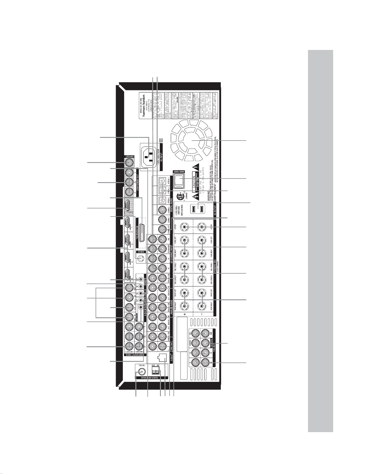
9
REAR - PANEL CONNECTIONS
Analog 1-5 Inputs
6/8 Channel
Inputs
Video
1, 2 & 3
Inputs
Remote
IR Input
Zone 2
IR Input
SIRIUS
Tuner
The Bridge III
Remote
IR Output
HDMI 1-4
Inputs
HDMI
Monitor
Output
Video
Monitor
Output
Center
Speaker
Outputs
Switched AC
Accessory
Outlet
Main
Power
Switch
Component
1 & 2
Inputs
Surround
Back/
Zone 2
Speaker
Outputs
Front
Speaker
Outputs
Zone 2 Audio Outputs
AM Antenna
FM Antenna
Carrier IR
Output
Analog 2 & 4
Audo Outputs
Surround
Speaker
Outputs
A-BUS Port
Component Video
Monitor Output
AC Power Input
Video 2
Output
A-BUS
IR Output
Subwoofer
Output
C
oaxial
Digital
Audio
Output
Coaxial 1 & 2
Digital Audio
Inputs
Optical 1-3
Digital
Audio
Inputs
Preamp
Outputs
Fan Vents
NOTE: To make it easier to follow the instructions throughout the manual that refer to this illustration, a copy of this page may be downloaded from the Product
Support section at www.harmankardon.com.

10
REAR - PANEL CONNECTIONS
Main Power Switch: This mechanical switch turns the
power supply on or off. It is usually left on, and cannot be turned
on or off using the remote control.
6-/8-Channel Inputs: Connect the multichannel analog
audio outputs of a non-HDMI player (DVD-Audio, SACD
™
, Blu-ray
Disc
™
or HD-DVD, or any other external decoder) to these jacks.
See page 30 for more information.
Coaxial 1/2 and Optical 1/2/3 Digital Audio
Inputs: If a source has a compatible digital audio output, and
if you are not using an HDMI connection for audio for the device,
connect it to one of these jacks to hear digital audio formats, such
as Dolby Digital, DTS and linear PCM. Use only one type of digital
audio connection for each source.
Coaxial Digital Audio Outputs: If a source is also
an audio recorder, connect the Coaxial Digital Audio Output to the
recorder’s matching input for improved recording quality. Only PCM
digital audio signals are available for recording. Both coaxial and
optical digital audio signals are available at this Digital Audio Output.
SIRIUS Tuner Jack: Plug in a SIRIUS satellite radio tuner
module here.
Zone 2 Infrared (IR) Input: Connect a remote IR receiver
located in the remote zone of a multizone system to this jack to
control the AVR (and any source devices connected to the Remote
IR Output) from the remote zone.
Remote Infrared (IR) Input and Output: When the
remote IR receiver on the front panel is blocked, connect an optional
IR receiver to the Remote IR Input jack. The Remote IR Output may
be connected to the Remote IR Input of a compatible product to
enable remote control through the AVR.
Remote IR Carrier Output: This output is similar in
function to the Remote IR Output, with the difference that this jack
outputs the full infrared signal as received by the AVR’s IR sensor
or the Remote IR Input, while the Remote IR Output jack outputs a
“stripped” signal that has no carrier frequency.
A-BUS IR Output: This is an additional IR output that may
only be controlled through the A-BUS system. Use it as a dedicated
connection to sources used only with the A-BUS system.
HDMI Inputs and Output: HDMI (High-Definition
Multimedia Interface) is a connection for transmitting digital audio
and video signals between devices. Connect up to four HDMI-
equipped source devices to the HDMI inputs using a single-cable
connection.
When you connect the HDMI Output to your video display, the
AVR 3600 will automatically transcode analog video signals to the
HDMI format, upscaling to as high as 1080p.
NOTES: When connecting a DVI-equipped display to one of
the HDMI Outputs:
• Use an HDMI-to-DVI adapter.
• Make sure the display is HDCP-compliant. If it isn’t, do not connect
it to an HDMI Output; use an analog video connection instead.
• Always make a separate audio connection.
Analog 1 – 5 Inputs: Connect the left and right analog
audio outputs of a source device to any of these inputs. These
inputs may be paired with any video inputs.
NOTES:
• The Analog 2 and 4 inputs are each associated with a set
of outputs. Consider using these connectors for an audio or
video recorder.
• You may optionally connect a source to both an analog and
digital audio input. This is useful for making recordings, for
multizone applications or simply as a backup.
Analog 2 and 4 Outputs: Connect either of these analog
audio outputs to the analog audio inputs of a recording device.
A signal is available at these outputs whenever an analog audio
source is playing.
Zone 2 Audio Outputs: Connect these jacks to an external
amplifier to power the speakers in the remote zone of a multizone
system.
Subwoofer Output: If you have a powered subwoofer
with a line-level input, connect it to the Subwoofer Output.
The Bridge III Input: Connect the included Harman Kardon
docking station to this input for use with most docking
iPod models, 4G and later, iPhone or iPhone 3G (not included). Turn
the receiver off (Standby mode) when connecting The Bridge III.
Fan Vents: This area contains vents used by the AVR 3600’s
fan to cool the system. Maintain a clearance of at least 3 inches
from the nearest surface to avoid overheating the unit. It is normal
for the fan to remain off at most normal volume levels. An automatic
temperature sensor turns the fan on only when it is needed.
IMPORTANT NOTE: Never block the fan vents, as doing
so could allow the AVR to overheat to dangerous levels.
Video 1/2 / 3 Inputs: Use these jacks to connect your video-
capable source components (e.g., VCR, DVD player, cable
TV box) to the receiver. Use only one type of video connection for
each source.
Video 2 Output: Connect this analog video output to the
composite video input of a recording device. A signal is available
at this output whenever an analog video source is playing.
Video Monitor Output: If any of your sources use
composite video connections, connect this monitor output to the
corresponding input on your video display. If your video display
is equipped with HDMI or component video inputs, this connection
is unnecessary, as the AVR 3600 will convert the composite video
source signal to the correct format for a single video-cable
connection to the TV.
Component Video 1/2 Inputs: If a video source has
analog component video (Y/Pb/Pr) capability, and if you are not
using an HDMI connection, connect the component video outputs
of the source to one of the sets of component video inputs. Do not
make any other video connections to that source.

11
REAR - PANEL CONNECTIONS
Component Video Monitor Outputs: If you are
using one of the Component Video Inputs and your television or
video display is component-video-capable (but does not have an
HDMI input), connect these jacks to the video display.
NOTES:
• Due to copy-protection restrictions, there is no output at
the Component Video Monitor Outputs for copy-protected
sources.
• Composite video signals are upscaled to as high as 1080i
and available at these outputs. If your video display’s best
connection is component video, it is the only video connec-
tion required from the AVR to the display.
AM and FM Antenna Terminals: Connect the included
AM and FM antennas to their respective terminals for radio reception.
Preamp Outputs: Connect these jacks to an external
amplifier if more power is desired. The Surround Back/Zone 2
Preamp Outputs may be used with an external amplifier to power
the remote zone of a multizone system.
A-BUS Port: Use a Category 5/5e cable to connect this port to
optional A-BUS equipment for multizone operation. When the A-BUS
system is used, it is possible to have a full 7.1-channel system in
the main listening room at the same time the multizone system is
in use.
Front, Center and Surround Speaker Outputs:
Use two-conductor speaker wire to connect each set of terminals
to the correct speaker. Remember to observe the correct polarity
(positive and negative connections).
Surround Back/Zone 2 Speaker Outputs: These
speaker outputs are used for the surround back channels in a
7.1-channel home theater, or may be reassigned to a remote room
for multizone operation.
Switched AC Accessory Outlet: You may plug the
AC power cord of one source device into this outlet, and it will turn
on whenever you turn on the receiver. Do not use a source that
consumes more than 50 watts of power.
AC Power Input: After you have made all other connections,
plug the AC power cord into this receptacle and into an unswitched
wall outlet.
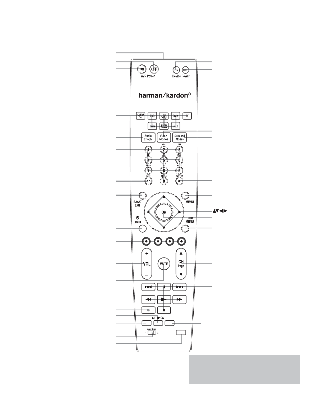
12
MAIN REMOTE CONTROL FUNCTIONS
AVR Power Off
AVR Power On
Source Selectors
Audio Effects
Alphanumeric Keys
Soft keys
Volume
Mute
Device Power On
Device Power Off
Surround Modes
Video Modes
OK
Navigation
Activity
Menu
Disc Menu
Channel
Sleep Settings
Learn
Transport Controls
IR Transmitter Lens
Last
Back/Exit
Light
Record
Info Settings
Setup
Zone Selector
LEARN
SETUP
INFO SLEEP
NOTE: To make it easier to follow the instructions
throughout the manual that refer to this illustration,
a copy of this page may be downloaded from the
Product Support section at www.harmankardon.com.

13
MAIN REMOTE CONTROL FUNCTIONS
The AVR 3600 remote is capable of controlling 8 devices, including
the AVR itself and an iPod docked in the included The Bridge III.
During the installation process, you may program the codes for
each of your source components into the remote. To operate a
component, press its Selector button to change the device mode.
Each Source Selector has been preprogrammed to control certain
types of components, with only the codes specific to each brand
and model changing, depending on which product code is pro-
grammed. The AUX and Cable/SAT Source Selectors may be used
for multiple device types, depending on the first digit of the product
code. Other Source Selectors may be reassigned to other device
types (see Initial Setup section).
AUX Source Sector: CD player product codes begin with
0, 1 or 2. VCR codes begin with 3 or 4. HDTV set-top box codes
begin with 6, PVD codes begin with 7 and TiVo
®
set-top box codes
begin with 8.
Cable/SAT Source Selector: Cable set-top box codes begin
with 0, 1 or 2, and satellite set-top box codes begin with 3 or 4.
IMPORTANT NOTE: All of the AVR 3600’s audio and
video inputs are independently assignable. Select the inputs
to which the device is physically connected during Initial
setup. Any device may be connected to any compatible input
and given any name (e.g., DVD or Game).
Most of the buttons on the remote have dedicated functions,
although the precise codes transmitted vary depending on the
device mode. Due to the wide variety of functions for various source
devices, we have included only a few of the most-often used
functions on the remote: alphanumeric keys, transport controls,
television-channel control, menu access and power on and off.
Buttons dedicated to the AVR are available at any time, even in
another device mode: AVR Power On and Off, Audio Effects,Video
Modes, Surround Modes, Volume, Mute and Sleep Settings. Press
the Setup button near the bottom of the remote to return it to
AVR mode.
A button’s function depends on which component is being controlled.
See Table A13 in the appendix for listings of the functions for each
type of component.
IR Transmitter Lens: As buttons are pressed on the
remote, infrared codes are emitted through this lens.
AVR Power On Button: Press to turn on the AVR. The
Master Power Switch on the rear panel must be on.
Device Power Off Button: Press a device’s Source
Selector, then press this button to turn off the device.
Device Power On Button: Press a device’s Source
Selector, then press this button to turn on the device.
Mute Button: Press to mute the AVR 3600’s speaker and
headphone outputs. To end the muting, press this button, adjust
the volume, or turn off the receiver.
AVR Power Off Button: Press to turn off the AVR 3600.
Source Selectors: Press one of these buttons to select a
source device, e.g., DVD, CD, cable TV, satellite or HDTV tuner. This
will also turn on the receiver and switch the remote’s device mode
to operate the source. The first press of the Radio Selector switches
the AVR to the last-used tuner band (AM, FM or SIRIUS). Each suc-
cessive press changes the band.
Audio Effects: Press to directly access the Audio Effects
submenu, which allows adjustment of the AVR’s tone and other
audio controls. See the Initial Setup section for more information.
Video Modes: Press for direct access to the Video Modes
submenu, which contains picture settings to be used after you have
adjusted the picture settings on the video display or TV. See the
Advanced Functions section for more information.
Surround Modes: Press to directly access the Surround
Modes submenu. Select a Surround mode category: Auto Select,
Virtual Surround, Stereo, Movie, Music or Video Game. The surround
mode will change when the menu line is highlighted.
To change the surround mode for the selected category, press the
OK Button when the menu line is highlighted and select one of the
available surround mode options, using the 1/5 Buttons. Press the
OK Button, then press the Back/Exit Button to exit the Surround
Modes menu and display the next higher menu in the hierarchy.
See the Advanced Functions section for more information on
surround modes.
Sleep Settings Button: Press to activate the sleep timer,
which turns off the receiver after a programmed period of time of
up to 90 minutes. Each press increases the timer by 10 minutes,
ending with the “Sleep Off” message.
Volume Control: Press to raise or lower the volume.
Navigation
(
1/57/3
)
and OK Buttons: These
buttons are used to make selections within the menu system and
to operate the tuner.
Alphanumeric Keys: Use these buttons to enter numbers
for radio station frequencies or to select station presets.
Last Channel: When controlling a cable, satellite or HDTV
set-top box or a TV, press this button to return to the previous
television channel.
Activity: With this button, up to eleven Activities may be
programmed to transmit a series of commands with a single press.
Execute an Activity by pressing this button, then the Alphanumeric
Key (or the AVR Power On or Off Button) into which it was programmed.
See the Advanced Functions section for more information on Activities.
Back/Exit: Press to return to the previous menu or to exit the
menu system.
Menu Button: This button is used within the Now Playing
menu for the tuner (including SIRIUS Radio), and The Bridge III, and
to display the main menu on some source devices. To display the
AVR 3600’s main menu, press the Setup Button.
Disc Menu: While a DVD is playing, press the DVD Source
Selector, then this button, to display the disc’s menu.

14
MAIN REMOTE CONTROL FUNCTIONS
Soft keys: These buttons are used with some source devices.
See Table A13 in the appendix for details. They are also used with
a Teletext-capable television if your broadcast, cable or satellite
provider offers Teletext service.
Channel/Page Control: When the tuner has been select-
ed, this control selects a preset radio station. While operating a
cable, satellite or HDTV set-top box or a television, press these but-
tons to change channels.
Record Button: Use this button to make recordings when an
audio or video recorder is in use.
Setup Button: Press to display the AVR’s Main Menu, or to
switch the remote to AVR device mode.
Info Settings Button: Press to display the AVR’s Info
Menu, which contains the settings for the current source.
Source Settings Button: Press a Source Selector and
then this button to display a source device’s settings menu.
Zone Selector: Use this switch to select whether AVR
commands will affect the main listening area (Zone 1) or the remote
zone of a multizone system (Zone 2). For normal operation, leave
the switch in the Zone 1 position.
Track Skip: These buttons are used with source components
to change tracks or chapters.
Transport Controls: These buttons are used to control
source components and The Bridge III.
Light: Press to illuminate the buttons on the remote. Press it
again to turn the backlight off, or wait ten seconds after the last
button press for the light to turn off on its own.
Learn: The AVR 3600 remote is capable of “learning” individual
IR codes from the original remote that came with a source device.
See page 16 in the Installation section.
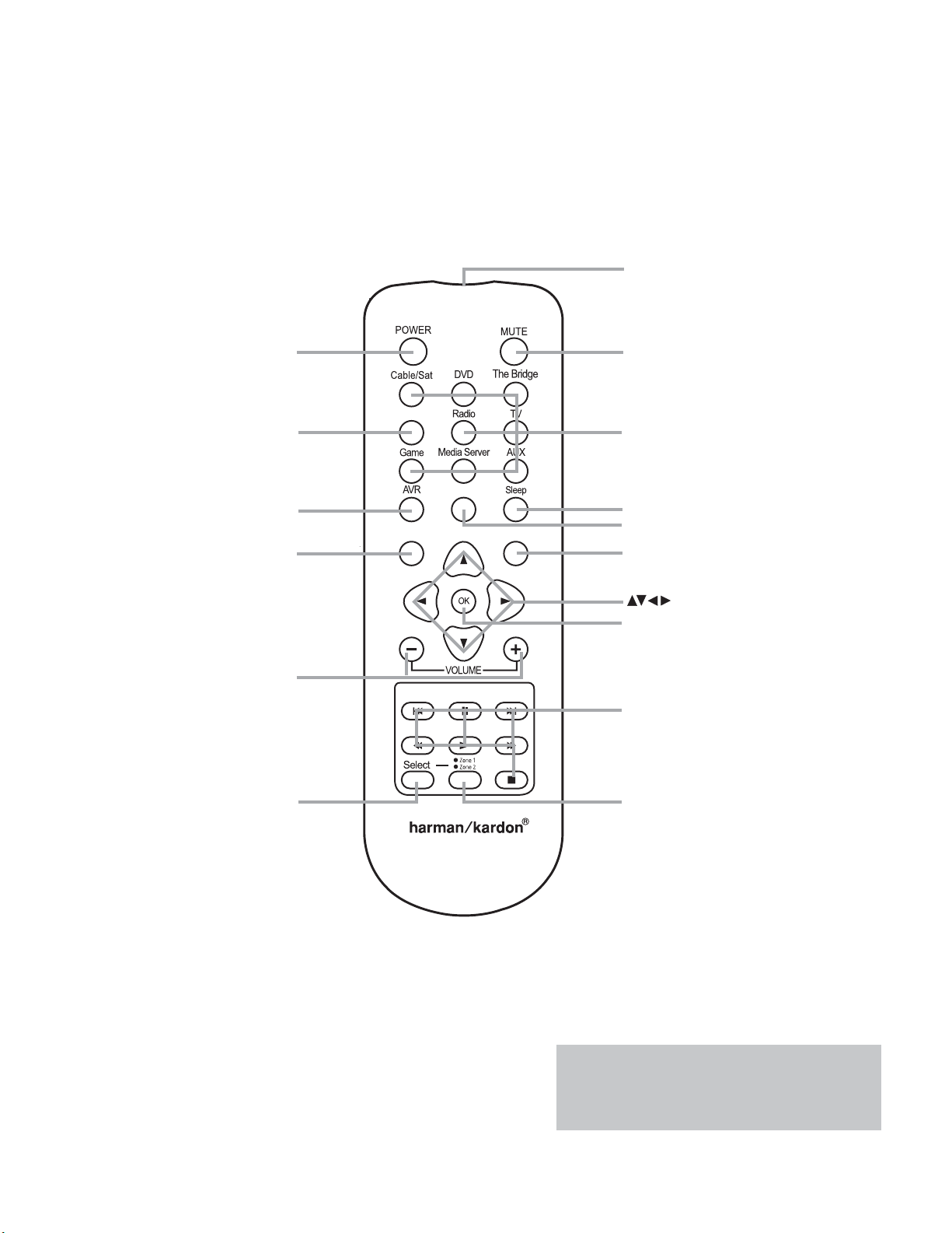
15
ZONE 2 REMOTE CONTROL FUNCTIONS
Info
Back/Exit Menu
IR Transmitter
Mute
Navigation
Power Off
Not Used
Zone Selector
OK
Transport Controls
Zone Indicator
Volume Controls
Back/Exit
Menu
Source Selectors
Sleep Settings
Info Settings
AVR
OFF
ZR 60
NOTE: To make it easier to follow the instructions
throughout the manual that refer to this illustration,
a copy of this page may be downloaded from the
Product Support section at www.harmankardon.com.

16
ZONE 2 REMOTE CONTROL FUNCTIONS
The Zone 2 remote control is used in the remote zone of a multizone
system with an IR receiver connected to the Zone 2 IR Input or an
A-BUS device. It may be used to control the power, volume and
mute functions or to select a source input for the remote zone, and
to control a Harman Kardon source connected to one of the AVR’s
Remote IR Outputs or the A-BUS IR Output.
The Zone 2 remote may also be used in the main listening room
to directly control the AVR 3600 and Harman Kardon DVD, CD or
tape players. When the Zone Selector is pressed to switch the remote
to Zone 1 mode (the Zone Indicator will turn green), the power,
volume and mute controls will only affect the main listening area.
To control operation for the remote zone, press the Zone Selector
so that the Zone Indicator turns red.
The Zone 2 remote requires two AAA batteries (included) that are
installed in the battery compartment on the back of the remote. Make
sure to observe proper polarity by matching the + and – symbols
on the batteries to the symbols printed inside the compartment.
IR Transmitter: This lens emits infrared codes when buttons
on the remote are pressed.
Power Off: Press to turn the AVR 3600 off. The Zone 2 remote
has no Power On Button, since the AVR turns on its multizone system
automatically when any of the Input Selectors is pressed, while the
remote is in Zone 2 mode; even if the AVR itself is in Standby mode.
When in the main listening room, press any Input Selector or the AVR
Selector to turn on the AVR 3600.
Mute: Press to mute the AVR 3600’s remote zone speakers tem-
porarily.To end the muting, press this button, adjust the volume,
or turn off the multizone system. Make sure to switch the remote
to Zone 2 mode, so that only the remote zone will be affected.
Source Selectors: With the remote in Zone 2 mode, press
one of these buttons to select a source device for the remote zone.
It will also turn on the multizone system and switch the remote to
the source’s device mode. You may select a different external
source device than that for the main room, but not different tuner
bands. If you select the same source as that for the main room,
then any commands sent to the source will affect both zones. The
first press of the Radio Selector switches the AVR to the last-used
tuner band (AM, FM or SIRIUS). Each successive press changes the
band.
The DVD Source Selector may be used to operate either a Harman
Kardon Blu-ray Disc player, or a Harman Kardon DVD player. The
default mode is to operate a Harman Kardon Blu-ray Disc player.To
toggle between Harman Kardon Blu-ray Disc-player and DVD-player
operation, press and hold the DVD Source Selector for 2 seconds.
The source selector will flash twice to confirm that the remote’s
mode has changed to operate the other type of disc player.
NOTE: The blank button to the left of the Radio Selector is
not used, even though pressing it causes the Zone Indicator
to light up.
Transport Controls: These buttons are used to control
The Bridge III and many source components.
Setup Button: Press to turn on the AVR and select the last-
used source. It is also used to switch the remote to AVR device
mode.
Info Settings Button: In Zone 1 mode, press to display
the AVR’s Info Setting’s Menu, which contains the settings for the
current source.
Sleep Settings Button: Press to activate the sleep timer,
which turns off the receiver after a programmed period of time of
up to 90 minutes. Each additional press increases the timer by
10 minutes, ending with the “Sleep Off” message.
Back/Exit: Press to return to the previous menu or to exit the
menu system.
Menu Button: This button is used within the Now Playing
menu for the tuner (including SIRIUS Radio), and The Bridge III, and
to display the main menu on some source devices.
Navigation
(
1/57/3
)
and OK Buttons: These buttons
are used to make selections within the menu system and also to
operate the tuner and The Bridge III.
Zone Selector and Zone Indicator: Each press
of the Zone Selector determines whether the AVR commands will
affect the main listening area (Zone 1) or the remote zone (Zone 2).
The Zone Indicator will turn green when Zone 1 has been selected,
and red for Zone 2. The Zone Indicator will also light briefly when
any button is pressed.
Volume Controls: Press to raise or lower the volume level
in the remote zone.

17
INTRODUCTION TO HOME THEATER
This introductory section will help you to familiarize yourself with
some basic concepts unique to multichannel surround sound
receivers, which will make setup and operation smoother.
Typical Home Theater System
A home theater typically includes an audio/video receiver, which
controls the system; a disc player; a source component for television
broadcasts (cable box, satellite dish receiver, HDTV tuner or antenna
connected to the TV); a video display (television); and loudspeakers.
Multichannel Audio
The main benefit of a home theater system is the placement of
loudspeakers around the room to produce “surround sound.”
Surround sound immerses you in the presentation for increased
realism.
The AVR 3600 may have up to seven speakers connected directly to
it, plus a subwoofer. Each main speaker is powered by its own
amplifier channel inside the receiver. A system with more than two
speakers is called a multichannel system.
• Front Left and Right – The main speakers are used as
in a 2-channel system. In many surround modes, these speakers
are secondary, while the main action, especially dialogue, is
moved to the center speaker.
• Center – The center speaker is used for dialogue in movies
and television programs, allowing the dialogue to originate near
the actors’ faces, for a more natural sound.
• Surround Left and Right – The surround speakers
improve directionality of ambient sounds. In addition, more loud-
speakers play dynamic soundtracks without risk of overloading
any one speaker.
• Surround Back Left and Right – Additional surround
speakers may be placed behind the listening position, improving the
precision of ambient sounds and allowing for more realistic pans.
The surround back speakers are used with surround modes
designed for 7.1-channel systems, such as Dolby Digital EX,
Dolby Digital Plus, Dolby TrueHD, DTS-ES (Discrete and Matrix),
DTS-HD High Resolution Audio, DTS-HD Master Audio and Logic 7
(7.1 modes). The surround back speakers are optional, and the
AVR 3600 may be set up with a 5.1-channel system in the main
listening area, and the surround back channels reassigned to a
multizone system, where the surround back channels power
loudspeakers located in another room.
Many people expect the surround speakers to play as loudly as
the front speakers. Although all of the speakers in the system will
be calibrated to sound equally loud at the listening position, most
artists use the surround speakers for ambient effects only, and
they program their materials to steer very little sound to these
speakers.
• Subwoofer – A subwoofer is designed to play only the lowest
frequencies (the bass). It augments smaller, limited-range satellite
speakers used for the other channels. Many digital-format programs,
such as movies recorded in Dolby Digital, contain a low-frequency
effects (LFE) channel which is directed to the subwoofer. The LFE
channel packs the punch of a rumbling train or airplane, or the
power of an explosion, adding realism and excitement to your
home theater. Some people use two subwoofers, for additional
power and even distribution of the sound.
Surround Modes
There are different theories as to the best way to present surround
sound and to distribute information to the speakers. A variety of
algorithms have been developed in an effort to reproduce the way we
hear sounds in the real world, resulting in a rich variety of options.
Several companies have taken surround sound in different directions:
• Dolby Laboratories – Dolby TrueHD, Dolby Digital Plus,
Dolby Digital, Dolby Digital EX, Dolby Pro Logic II and IIx, Dolby
Virtual Speaker, Dolby Headphone
• DTS – DTS-HD High Resolution Audio, DTS-HD Master Audio,
DTS, DTS-ES (Discrete and Matrix), DTS Neo:6, DTS 96/24
• Harman International (the Harman Kardon
parent company) – Logic 7
• Stereo Modes – Generic modes that expand upon conven-
tional 2-channel stereo, including 5- and 7-channel stereo
Table A13 in the appendix contains detailed explanations of the
mode groups and the mode options available within each group.
Digital modes, such as Dolby Digital and DTS, are only available
with specially encoded programs, such as HDTV, Blu-ray Disc media
and digital cable or satellite television. Other modes may be used
with digital and analog signals to create a different surround presen-
tation, or to use a different number of speakers. Surround Mode
selection depends upon the number of speakers in your system, the
materials you are watching or listening to, and your personal tastes.
18
CONNECTIONS
There are different types of audio and video connections used
to connect the receiver, the speakers, the video display, and the
source devices. The Consumer Electronics Association has estab-
lished the CEA
®
color-coding standard. See Table 1.
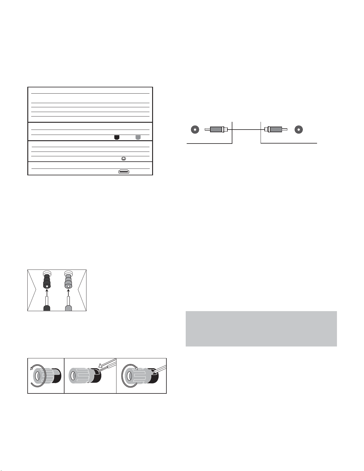
Table 1 – Connection Color Guide
Speaker Connections
Speaker cables carry an amplified signal from the receiver’s speaker
terminals to each loudspeaker. They contain two wire conductors,
or leads, inside plastic insulation, that are differentiated in some
way, such as with colors or stripes.
The differentiation preserves polarity, without which low-frequency
performance can suffer. Each speaker is connected to the receiver’s
speaker-output terminals using two wires, one positive (+) and one
negative (–). Always connect the positive terminal on the speaker,
which is usually colored red, to the positive terminal on the receiver,
which is colored as indicated in the Connection Color Guide (Table
1). The negative terminals are both black.
The AVR 3600 uses binding-post
speaker terminals that can accept
banana plugs or bare-wire cables.
Banana plugs are inserted into the
hole in the middle of the terminal
cap. See Figure 1.
Figure 1 – Binding-Post Speaker Terminals With Banana Plugs
Bare wire cables are installed as follows (see Figure 2):
1. Unscrew the terminal cap until the pass-through hole is revealed.
2. Insert the bare end of the wire into the hole.
3. Hand-tighten the cap until the wire is held snugly.
Figure 2 – Binding-Post Speaker Terminals With Bare Wires
Subwoofer
The subwoofer is dedicated to the low frequencies (bass), which
require more power.To obtain the best results, most speaker
manufacturers offer powered subwoofers that contain their own
amplifier. Usually, a line-level (nonamplified) connection is made
from the receiver’s Subwoofer Output to a corresponding jack
on the subwoofer, as shown in Figure 3.
Although the purple subwoofer outputs look similar to full-range
analog audio jacks, they are filtered to allow only the low frequencies
to pass. Don’t connect these outputs to any other devices.
Figure 3 – Subwoofer
CONNECTING SOURCE DEVICES
TO THE AVR
Audio and video signals originate in “source devices,” including
your Blu-ray Disc or DVD player, CD player, DVR (digital video
recorder) or other recorder, tape deck, game console, cable or
satellite television box or MP3 player.The AVR’s tuner also counts
as a source, even though no external connections are needed,
other than the FM and AM antennas and the SIRIUS tuner module.
Separate connections are required for the audio and video portions
of the signal, except for digital HDMI connections. The types of
connections used depend upon the capabilities of the source device
and video display.
Audio Connections
There are two types of audio connections: digital and analog.
Digital audio signals are required for listening to sources encoded
with digital surround modes, such as Dolby Digital and DTS, or for
noncompressed PCM digital audio. There are three types of digital
audio connections: HDMI, coaxial and optical. Do not use more
than one type of digital audio connection for each source device.
However, it’s okay to make both analog and digital audio connec-
tions to the same source.
NOTE: HDMI signals may carry both audio and video. If your
video display device has an HDMI input, make a single HDMI
connection from each source device to the AVR. Usually, a
separate digital audio connection is not required. Turn the
volume on your television all the way down.
Digital Audio
The AVR 3600 is equipped with four HDMI (High-Definition
Multimedia Interface) inputs, and one output. HDMI technology
enables digital audio and video information to be carried using
a single cable, delivering the highest quality picture and sound.
The AVR 3600 uses HDMI (V.1.3a with Deep Color) technology and
is capable of processing both the audio and video components of
the HDMI data, minimizing the number of cable connections
in your system. The AVR 3600 implements Deep Color, which
increases by an order of magnitude the shades of color that can
be displayed, and the latest lossless multichannel audio formats,
including Dolby TrueHD and DTS-HD Master Audio.
SubwooferPreout
12 3
+
Audio Connections
Left Right
Front (FL/FR)
Center (C)
Surround (SL/SR)
Surround Back (SBL/SBR)
Subwoofer (SUB)
Digital Audio Connections
Coaxial
Optical
Video Connections
Component Y Pb Pr
Composite
S-Video
HDMI
™
Connections (digital audio/video)
HDMI
Input Output
White Red
Green
Blue Gray
Brown Tan
Purple
Orange
Green Blue Red
Yellow
19
CONNECTIONS
NOTE: Some DVD-Audio, SACD, Blu-ray Disc and HD-DVD
players only output multichannel audio through their multi-
channel analog outputs. Make a separate analog audio con-
nection in addition to the HDMI connection, which is still used
for video and to listen to Dolby Digital, DTS or PCM materials
that may be stored on the disc.
The AVR 3600 converts analog video signals to the HDMI format,
including its on-screen menus, upscaling to high-definition 1080p
resolution.
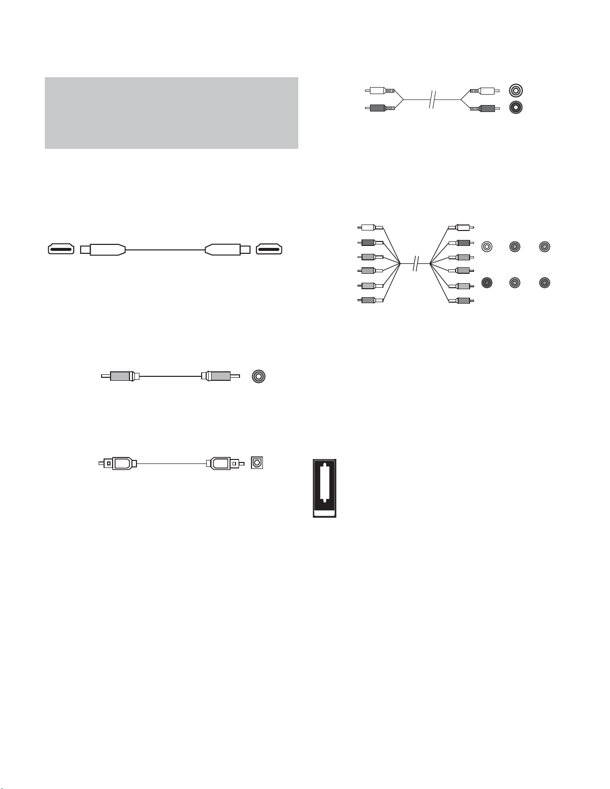
The HDMI connector is shaped for easy plug-in (see Figure 4). If
your video display has a DVI input and is HDCP-compliant, use an
HDMI-to-DVI adapter (not included). A separate audio connection is
required. HDMI cable runs are limited to about 10 feet.
Figure 4 – HDMI Connection
If your video display or source device is not HDMI-capable, use one
of the analog video connections (composite or component video)
and a separate audio connection.
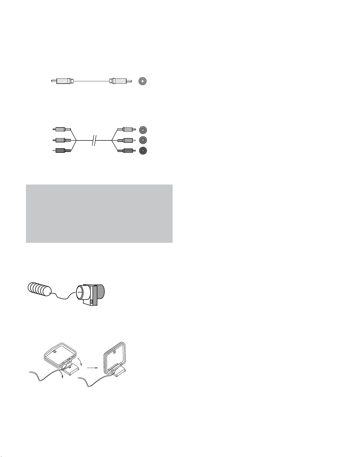
Coaxial digital audio jacks are usually color-coded in orange.
Although they look similar to analog jacks, you should not connect
coaxial digital audio outputs to analog inputs or vice versa. See
Figure 5.
Figure 5 – Coaxial Digital Audio
Optical digital audio connectors are normally covered by a shutter
to protect them from dust. The shutter opens as the cable is insert-
ed. Input connectors are color-coded using a black shutter, while
outputs use a gray shutter. See Figure 6.
Figure 6 – Optical Digital Audio
Analog Audio
Analog connections require two cables, one for the left channel
(white) and one for the right channel (red). These two cables are
often attached to each other. See Figure 7.
For sources that are capable of both digital and analog audio, you
may make both connections.
The analog audio connection is required for multizone operation,
as the AVR 3600’s multizone system is not capable of converting a
digital signal to analog format. Use the analog audio connections
even with the Surround Back/Zone 2 speaker outputs, in case
another 2-channel digital audio source is in use in the main listen-
ing area. The AVR 3600 is only capable of processing one PCM
source at a time.
You may only record materials from DVDs or other copy-protected
sources using analog connections. Remember to comply with all copy-
right laws, if you choose to make a copy for your own personal use.
Figure 7 – Analog Audio
The 6-/8-Channel Inputs are multichannel analog connections that
are used with high-definition sources that decode the copy-protected
digital content, such as some DVD-Audio, SACD, Blu-ray Disc and
HD-DVD players. See Figure 8. The multichannel analog audio con-
nection is not required for players compliant with HDMI version 1.1
or better, or that output linear PCM signals via an HDMI connection.
Consult the owner’s guide for your disc player for more information
and see page 30.
Figure 8 – Multichannel Analog Audio
The AVR 3600 also includes a proprietary, dedicated audio connec-
tion for The Bridge III docking station for iPod or iPhone. If you own
a docking iPod (most models, 4G or later), iPhone or iPhone 3G,
connect The Bridge III (included) to The Bridge III port on the receiver.
See Figure 9. Dock your iPod or iPhone (not included) in The Bridge III,
and you may listen to your audio materials through your high-
performance audio system. You may view still images or video
materials stored on a photo- or video-capable iPod that supports
video browsing or iPhone. Use the AVR 3600 remote to control the
iPod, with navigation messages displayed on the front panel and on
a video display connected to the AVR.The Bridge III outputs analog
audio to the AVR 3600, and is available to the multizone system.
Figure 9 – The Bridge III port
Video Connections
Many sources output both audio and video signals (e.g., Blu-ray
Disc or DVD player, cable television box, HDTV tuner, satellite box,
VCR, DVR). In addition to the audio connection, make one type of
video connection for each of these sources (only one at a time for
any source).
Digital Video
If you have already connected a source device to one of the HDMI
inputs, you have automatically made a video connection, as the
HDMI signal includes both digital audio and video components.
Analog Video
There are two types of analog video connections used on the
AVR 3600: composite video and component video.
Composite video is the basic connection most commonly available.
The jack is usually color-coded yellow, and looks like an analog
THE BRIDGE
Multichannel
analog audio
cable (RCA)
Front Surround Center
White
Red Gray Purple
Blue Green
Subwoofer
L
R
A
nalog audio
cable (RCA)
Optical
Optical digital
audio cable
Coaxial
Coaxial digital
audio cable
20
CONNECTIONS
audio jack. Do not plug a composite video cable into an analog or
coaxial digital audio jack, or vice versa. Both the chrominance
(color) and luminance (intensity) components of the video signal
are transmitted using a single cable. See Figure 10.
Figure 10 – Composite Video
Component video separates the video signal into three compo-
nents – one luminance (“Y”) and two sub-sampled color signals
(“Pb” and “Pr”) – that are transmitted using three separate cables.
See Figure 11.
Figure 11 – Component Video
If it’s available on your video display, an HDMI connection is recom-
mended as the best quality connection, followed by component
video, and then composite video.
NOTES:
• Copy-protected sources are not available at the Component
Video Monitor Outputs.
• Standard and high-definition analog video signals maybe
upscaled to 1080i resolution for the Component Video
Monitor Outputs. For improved video performance, consider
upgrading to an HDMI-capable video display with 1080p
resolution.
ANTENNAS
The AVR 3600 uses separate terminals for the included FM and AM
antennas.
The FM antenna uses a 75-ohm F-connector. See Figure 12.
Figure 12 – FM Antenna
The AM loop antenna needs to be assembled. Connect the two leads
to the spring terminals on the receiver. The AM antenna leads have
no polarity, and you may connect them to either terminal. See
Figure 13.
Figure 13 – AM Antenna
To enjoy SIRIUS satellite radio, purchase a SIRIUS Ready tuner module
and a subscription to the SIRIUS service. Visit www.sirius.com
for information on Sirius-Ready tuner modules. The AVR 3600 is
compatible with the Sirius-Connect SC-H1 tuner module, using the
8-pin DIN cable included with the module, and it provides power for
the tuner module, so that it is not necessary to use the AC adapter
supplied with the tuner module. Although you may use a module
with standard audio connections, labeled for “car and home use,”
you will not be able to enjoy the AVR 3600’s ease of control.
USB PORT
The USB Port on the AVR 3600 is used only for software upgrades.
If an upgrade for the receiver’s operating system is released in the
future, it may be downloaded to the AVR using this port. Complete
instructions will be provided at that time.
Component
video cable
Green
Blue
Red
Y
Pb
Pr
Composite
video cable
 Loading...