


AVR-40
Ref
Volume
Wrap
Contour
Monitor
Bass Treble Balance
Video 3
Video L–Audio–R
KHz
MHz
TUNED AUTO TAPE M
HALL
SLEEP
PRESET
STEREO
Pro Logic
ms
Harman Kardon
AVR40
Audio/VideoReceiver
Owner’s Manual

Owner’s Manual
AVR40 Audio/Video Receiver
Table of Contents
Introduction . . . . . . . . . . . . . . . . . . . . . . . . . . . . . . . . . . 1
Features . . . . . . . . . . . . . . . . . . . . . . . . . . . . . . . . 1
Safety Information. . . . . . . . . . . . . . . . . . . . . . . . . . . . 2-3
Unpacking and Installation . . . . . . . . . . . . . . . . 3
Conventions. . . . . . . . . . . . . . . . . . . . . . . . . . . . . 3
Front Panel Controls . . . . . . . . . . . . . . . . . . . . . . . . . . 4-6
Rear Panel Connections . . . . . . . . . . . . . . . . . . . . . . . 7-8
Remote Control Functions . . . . . . . . . . . . . . . . . . . . 9-10
Installation and Configuration . . . . . . . . . . . . . . . . 11-14
Operation . . . . . . . . . . . . . . . . . . . . . . . . . . . . . . . . . 15-18
Wrap Circuitry . . . . . . . . . . . . . . . . . . . . . . . 16-17
Tuner Operation. . . . . . . . . . . . . . . . . . . . . . 17-18
Tape Recording. . . . . . . . . . . . . . . . . . . . . . . . . 18
Video Dubbing. . . . . . . . . . . . . . . . . . . . . . . . . . 18
Troubleshooting Chart . . . . . . . . . . . . . . . . . . . . . . . . . 19
Technical Specifications . . . . . . . . . . . . . . . . . . . . . . . . 20
©1997 Harman Kardon, Incorporated
80 Crossways Park West
Woodbury, NY 11797
www.harmankardon.com

Staple or clip original invoice here. ▼

Introduction
1
Congratulations! With the purchase
of a Harman Kardon AVR40 you are
about to begin many years of listening
enjoyment. The AVR40 has been custom
designed to provide all the excitement
and detail of movie soundtracks and
every subtle nuance of musical
selections.
While complex systems are hard at work
within the AVR40 to make all of this hap-
pen, hookup and operation are simple.
Color keyed connections, and a unique
remote control make the AVR40 easy to
use. To obtain the maximum enjoyment
from your new receiver we urge you to
take a few minutes to read through this
manual. This will ensure that connec-
tions to speakers, source playback units
and other external devices are made
properly. A few minutes spent learning
the functions of the various controls will
enable you to take advantage of all the
power the AVR40 is able to deliver.
If you have any questions about this
product, its installation or operation,
please contact your dealer. They are your
best local source of information. You
may also contact Harman Kardon
directly via the Internet at
www.harmankardon.com
Description and Features
The AVR40 is a full featured A/V receiver,
incorporating a wide variety of listening
options. Four audio inputs, three
audio/video inputs and the AVR40’s 30
preset tuner enable it to serve as the con-
trol center for a complete audio/video
system. A system remote control operates
the AVR40 and compatible Harman
Kardon source equipment.
■ Dolby* Pro Logic* Surround
Decoding
■ Exclusive Harman Kardon Wrap
Circuitry
■ System Remote Control
■ Direct Video Dubbing
■ Front Panel A/V Inputs for Games
or Camcorder Connection
■ System Memory for Surround
Modes
Safety Information
Important Safety Information
Verify Line Voltage Before Use
Your AVR40 has been designed foruse in
North America with 120 volt AC current.
Connection to a line voltage other than
that for which it is intended can create a
safety and fire hazard, and may damage
the amplifier.
If you have any questions about the volt-
age requirements for your specific model,
or about the line voltage in your area,
contact your dealer before plugging the
unit into a wall outlet.
Do Not Use Extension Cords
To avoid safety hazards, use only the
power cord supplied with your unit. If a
replacement cord is used, make certain
that it is of similar gauge. We do not rec-
ommend that extension cords be used
with this product. As with all electrical
devices, do not run power cords under
rugs or carpets or place heavy objects on
them. Damaged power cords should be
replaced immediately with cords meeting
factory specifications.
Handle The AC Power Cord Gently
When disconnecting the power cord from
an AC outlet, always pull the plug, never
pull the cord. If you do not intend to use
the amplifier for any considerable length
of time, disconnect the plug from the AC
outlet.
Do Not Open The Cabinet
There are no user serviceable compo-
nents inside this product. Opening the
cabinet may present a shock hazard, and
any modification to the product will void
your guarantee. If water or any metal
object such as a paper clip, wire or a
staple accidentally falls inside the unit,
disconnect it from the AC power source
immediately, and consult an authorized
service station.
CATV Or Antenna Grounding
If an outside antenna or cable system is
connected to this product, be certain that
it is grounded so as to provide some pro-
tection against voltage surges and static
charges. Section 810 of the National
Electrical Code, ANSI/NFPA No. 70-1984,
provides information with respect to
proper grounding of the mast and sup-
porting structure, grounding of the lead-
in wire to an antenna discharge unit,
size of grounding conductors, location of
antenna discharge unit, connection to
grounding electrodes and requirements
of the grounding electrode.
NOTE TO CATV SYSTEM INSTALLER:
This reminder is provided to call the
CATV (Cable TV)system installer’s atten-
tion to article 820-40 of the NEC that
provides guidelines for proper grounding
and, in particular, specifies that the cable
ground shall be connected to the ground-
ing system of the building, as close to the
point of cable entry as possible.
Installation Location
■ To assure proper operation, and to
avoid the potential for safety hazards,
place the unit on a firm and level
surface. When placing the unit on a
shelf, be certain that the shelf and
any mounting hardware can support
the weight of the product.
■ Make certain that proper space is pro-
vided both above and below the unit
for ventilation. If this product will be
installed in a cabinet or other enclosed
area, make certain that there is suffi-
cient air movement within the cabinet.
Under some circumstances a fan may
be required.
■ Do not place the unit directly on a
carpeted surface.
■ Avoid installation in extremely hot
or cold locations, or an area that is
exposed to direct sunlight or heating
equipment.
■ Avoid moist or humid locations.
■ Do not obstruct the ventilation slots on
the top of the unit, or place objects
directly over them.
2
CAUTION:
TO REDUCE THE RISK OF ELECTRIC SHOCK, DO NOT REMOVE
COVER (OR BACK). NO USER-SERVICEABLE PARTS INSIDE. REFER
SERVICING TO QUALIFIED SERVICE PERSONNEL.
WARNING:
TO REDUCE THE RISK OF FIRE OR ELECTRIC SHOCK,
DO NOT EXPOSE THIS APPLIANCE TO RAIN OR MOISTURE.
CAUTION:
TO PREVENT ELECTRIC SHOCK, MATCH WIDE
BLADE OF PLUG TO WIDE SLOT, FULLY INSERT.
ATTENTION:
POUR EVITER LES CHOCS ELECTRIQUES, INRODUIRE LA
LAME LA PLUS LARGE DE LA FICHE DANS LA BORNE CORRESPONDANTE DE
LA PRISE ET POUSSER JUSQU'AU FOND.
The lightning flash with arrowhead
symbol, within an equilateral triangle, is
intended to alert the user to the
presence of uninsulated “dangerous voltage”
within the product’s enclosure that may be of
sufficient magnitude to constitute a risk of
electric shock to persons.
The exclamation point within an
equilateral triangle is intended to
alert the user to the presence of
important operating and maintenance
(servicing) instructions in the literature
accompanying the appliance.
CAUTION
RISK OF ELECTRIC SHOCK
DO NOT OPEN

Safety Information
Cleaning
When the unit gets dirty, wipe it with a
clean, soft dry cloth. If necessary, wipe it
with a soft cloth dampened with mild
soapy water, then a fresh cloth with clean
water. Wipe dry immediately with a dry
cloth. NEVER use benzene, thinner,
alcohol or any other volatile cleaning
agent. Do not use abrasive cleaners, as
they may damage the finish of metal
parts. Avoid spraying insecticide near
the unit.
Moving The Unit
Before moving the unit, be certain to dis-
connect any interconnection cords with
other components, and make certain
that you disconnect the unit from the AC
outlet.
Important Information For The User
NOTE: This equipment has been tested
and found to comply with the limits for a
Class B digital device, pursuant to Part
15 of the FCC Rules. The limits are
designed to provide reasonable protection
against harmful interference in a resi-
dential installation. This equipment
generates, uses and can radiate radio fre-
quency energy and, if not installed and
used in accordance with the instructions,
may cause harmful interference to radio
communication. However, there is no
guarantee that harmful interference will
not occur in a particular installation. If
this equipment does cause harmful inter-
ference to radio or television reception,
which can be determined by tuning the
equipment off and on, the user is
encouraged to try to correct the interfer-
ence by one or more of the following
measures:
■ Reorient or relocate the receiving
antenna.
■ Increase the separation between the
equipment and receiver.
■ Connect the equipment into an outlet
on a circuit different from that to
which the receiver is connected.
■ Consult the dealer or an experienced
radio/TV technician for help.
This device complies with Part 15 of the
FCC Rules. Operation is subject to the fol-
lowing two conditions: (1) this device
may not cause harmful interference, and
(2) this device must accept interference
received, including interference that may
cause undesired operation.
NOTE: Changes or modifications may
cause this unit to fail to comply with
Part 15 of the FCC Rules and may void
the user’s authority to operate the
equipment.
Unpacking and Installation
The carton and shipping materials used
to protect your new AVR40 during ship-
ment were specially designed to cushion
it from shock and vibration. We suggest
that you save the carton and packing
materials for use in shipping if you move
or should the unit ever need repair.
To minimize the size of the carton in
storage, you may wish to flatten it. This
is done by carefully removing any staples
that attach the carton flaps to one
another, and then slitting the tape
covering the seams. Fold the carton down
to a more two dimensional appearance.
Packing materials that cannot be
collapsed should be saved along with the
carton in a plastic bag.
If you do not wish to save the packaging
materials, please note that the carton
and other sections of the shipping protec-
tion are recyclable. Please respect the
environment and discard those materials
at a local recycling center.
When positioning your AVR40 in its final
location, make certain that any shelf or
stand is capable of supporting its weight,
and that there is adequate ventilation on
all sides, as well as on the top and bot-
tom. Do not place CDs, record jackets,
owner’s manuals, or other paper on top
of, or beneath the unit. This will block
air flow, causing degraded performance
and a possible fire hazard. If the unit is
to be enclosed in a cabinet or rack, make
certain that there is adequate air circula-
tion, with a means provided for hot air to
exit, and for cool air to be brought in.
Conventions
In order to help you use this manual
with the remote control, front panel
controls, rear panel connections and
on-screen menus, certain conventions
have been used.
BOLD TYPE – will be used to indicate
a front or rear panel control. It will
typically be followed with a reference
number to the specific control being
described.
DISPLAY TYPE – will be used to indi-
cate messages that appear in the infor-
mation display window.
1 – A number within a Square refer-
ences a front panel control.
¡ – A number within a Circle refer-
ences a connection point on the rear
panel.
a – A number within an Oval refer-
ences a button on the remote control.
3
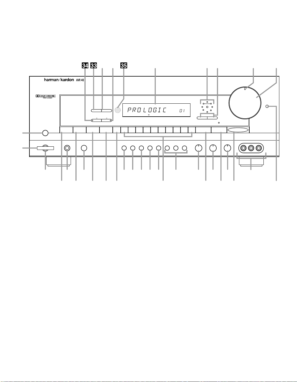
Front Panel Controls
4
Power
Center Rear Delay Calibrate Memory 1 2 3 4 5 6 7 8 9 0 Surround Ctr. Boost Tuning
Tuning Mode
P
.
Scan
Ref
Volume
Wrap
Contour
AM / FM CD
Speaker
Headpnone
Tape 1 Tape 2 TV Video 1 Video 2 Video 3
Bass Treble Balance
Video 3
Video 2 Video 1 Video 3 Video 1
Video L–Audio–R
KHz
MHz
TUNED AUTO TAPE M
HALL
SLEEP
PRESET
STEREO
Pro Logic
ms
Monitor
1
2
^& * Ó(
6789)345 !@
#
Ò
$
Ú
%
Û
Ùı˜ˆ¯¸˘
Ô
1 Main Power Switch
2 System Power Control
3 Power Indicator
4 Headphone Jack
5 Speaker Switch
6 AM/FM Selector
7 CD
8 Tape 1/Tape Monitor
9 Tape 2
) TV
! Video Sources
@ Bass Control
# Treble Control
$ Balance Control
% Video 3
^ Center Channel
& Rear Channel
* Delay Time Adjust
( Calibrate
Ó Tuner Memory Button
Ô Numeric Buttons
Surround Mode
Ò Center Boost
Ú Tuning Button
Û Contour
Ù Volume Control
ı Mute/Volume Indicator
ˆ Wrap
˜ Wrap Indicator
¯ Information Display
˘ Video 3
→
Video 1 Dubbing
¸ FM Mode
33
P
.
Scan Button
34
Video 2
→
Video 1 Dubbing
35
Remote Sensor

Front Panel Controls
1 Main Power Switch: Press this
button to apply power to the AVR40.
When the switch is pressed the unit
is placed in a Standby mode, as
indicated by the amber LED 3 sur-
rounding the System Power control
2. This button MUST be pressed in
to operate the unit regardless of the
status of the Power Switch at the
bottom of the front panel. To turn the
unit off and prevent the use of the
remote control, this switch should be
pressed until it pops out to extend
from the front panel so that the word
“OFF” may be read at the top of the
switch.
NOTE: In normal operation this
switch may be left in the “on”
position.
2 System Power Control: When
the Main Power Switch
1
is
pressed in, press this button to turn
on the AVR40, press it again to turn
the unit off. Note that the Power
Indicator surrounding the switch
3
will turn green when the unit is on.
3 Power Indicator: This LED will
illuminate in amber when the unit is
in the Standby mode, to signal that
the unit is ready to be turned on.
When the unit is in operation the
indicator will turn green.
4 Headphone Jack: This jack may
be used to listen to the AVR40’s out-
put through a pair of headphones.
Be certain that the headphones
have a standard
1
⁄4″ stereo phone
plug.
5 Speaker Switch: This switch
controls the front left/right speakers.
For normal operation it is pressed in
and sound is heard through the front
speakers. To silence the front
left/right speakers, push the button
once until it is in the “out” position.
When the front speakers are turned
off sound will continue to be heard
through the center and rear speakers
and the headphone jack.
6 AM/FM Selector: Press this but-
ton to select the tuner as your listen-
ing source. Press it again to change
between AM and FM frequency
bands.
7 CD: Press this button to select
your CD player as the listening
source.
8 Tape 1/Tape Monitor: Press this
button to select the recorder con-
nected to the Tape 1 Inputs∞ as
the listening source, or to monitor a
recording of another selected
source.
9 Tape 2: Press this button to select
the recorder connected to the Tape
2 Inputs £ as your listening source.
) TV: Press this button to select the
device connected to the TV Inputs
™ on the rear panel as your listen-
ing source.
! Video Sources: Press these but-
tons to select any of the sources
connected to an audio video input
¶• % as your listening source.
The selected input will also be
routed to the device connected to
the Video Monitor Output ‚ on the
rear panel.
NOTE: When the AVR40 is in the
Standby mode, as indicated by the
Power Indicator
3
illuminating in
amber, the unit may be turned on by
pressing any of the Source Selection
buttons 6789)!d.
@ Bass Control: Turn this control to
modify the low frequency output of
the left/right channels by as much as
±10dB. Set this control to a suitable
position for your taste and room
acoustics.
# Treble Control: Turn this control
to modify the high frequency output
of the left/right channels by as much
as ±10dB. Set this control to a suit-
able position for your taste and room
acoustics.
$ Balance Control: Turn this con-
trol to change the relative volume for
the front left/right channels.
NOTE: For proper operation of the
surround modes this control should
be at the midpoint, or “12 O’clock”
position.
% Video 3: This alternate set of
Audio/Video inputs may be used for
the connection of a camcorder or
video game. Select this input by
pressing the Video3 button ! on
the front panel.
^ Center Channel: Press this but-
ton to select the type of center chan-
nel speaker used. If there is no
center channel speaker, press the
button until the Information Display
¯ reads NO CENTR.
& Rear Channel: Press this button
to configure the AVR40 for the pres-
ence or absence of rear speakers.
* Delay Time Adjust: Press this
button to adjust the delay time
between the front and rear channels.
( Calibrate: Press this button to
turn on the calibration circuits that are
used to adjust the output levels of the
AVR40. Once the button is pressed
you may adjust the levels of the
center and rear channels using the
Level
Â
/Level
∏
buttons t on the
remote control while listening to the
current input source. To calibrate the
system using the internal test tone,
press this button first, and then
press the Calibrate button q on
the remote.
5
 Loading...