


®
®
.
AVR 240
AUDIO/VIDEO RECEIVER
OWNER’S MANUAL
AVR 240 |
|
|
|
|
|
DIGITAL |
LOGIC 7 |
VID 1 |
DVD |
|
|
PRO LOGIC |
|
VID 2 |
CD |
|
|
3 STEREO |
DSP |
VID 3 |
FMAM |
|
|
HEADPHONE |
5 7 CH. STEREO |
VID 4 |
TAPE |
|
|
|
SURR. OFF |
|
6 8 CH |
|
|
|
|
O |
cal 4 |
C |
ial 4 |
|
|
|
|
|
V |

AVR 240 AUDIO/VIDEO RECEIVER
3Introduction
4Important Safety Information
4Unpacking
5Front-Panel Controls
8 Rear-Panel Connections
11 Remote Control Functions
15Installation and Connections
16System and Power Connections
18System Configuration
18Speaker Selection and Placement
20System Setup
20Using the On-Screen Display
21Input Setup
22Audio Setup
22Surround Setup
24Automated Speaker Setup Using EzSet+
26Manual Setup
27Speaker Size
28Speaker Crossover Settings
29Delay Settings
30Output Level Adjustment
32Operation
32Basic Operation
32Source Selection
326-Channel/8-Channel Direct Input
32Volume and Tone Control
33Surround Mode Selection
34Surround Mode Chart
36Digital Audio Playback
37Surround Mode Post Processing
38Surround Mode Availability
39Tuner Operation
39Recording
40Using TheBridgeTM
40 Output Level Trim Adjustment
40 Dim Function
42 Advanced Features
44 Programming the Remote
44Programming Device Codes
44Macro Programming
45Programmed Device Functions
46Volume Punch-Through
46Channel Control Punch-Through
46Transport Control Punch-Through
46Resetting the Remote Memory
47Function List
49 Setup Code Tables
59Troubleshooting Guide
59Processor Reset
60Technical Specifications
60Trademark Acknowledgements
61Index
62Appendix – Settings Worksheet
Please register your product on our Web site at www.harmankardon.com. Note: You’ll need the product’s serial number. At the same time, you can choose to be notified about our new products and/or special promotions.
For Canadian model
This class B digital apparatus complies with Canadian ICES-003.
For models having a power cord with a polarized plug: CAUTION: To prevent electric shock, match wide blade of plug to wide slot, fully insert.
Modèle pour les Canadien
Cet appareil numérique de la classe B est conforme à la norme NMB-003 du Canada.
Sur les modèles dont la fiche est polarisee: ATTENTION: Pour éviter les chocs électriques, introduire la lame la plus large de la fiche dans la borne correspondante de la prise et pousser jusqu’au fond.
Typographical Conventions
In order to help you use this manual with the remote control, front-panel controls and rear-panel connections, certain conventions have been used.
EXAMPLE – (bold type) indicates a specific remote control or front-panel button, or rear-panel connection jack
EXAMPLE – (OCR type) indicates a message that is visible on screen or on the front-panel information display
1– (number in a square) indicates a specific front-panel control
¡ – (number in a circle) indicates a rear-panel connection
a– (number in an oval) indicates a button or indicator on the remote
The appearance of the text or cursor for your receiver’s on-screen menus may vary slightly from the illustrations in this manual. Whether the text appears in all uppercase or upperand lowercase characters, performance and operation remain the same.
2 TABLE OF CONTENTS

INTRODUCTION
Thank you for choosing Harman Kardon®! With the purchase of a Harman Kardon AVR 240, you are about to begin many years of listening enjoyment. Designed to provide all the excitement and detail of movie soundtracks and every nuance of musical selections, the AVR 240 accomplishes its mission by harnessing advanced technologies usually found only in higher-priced receivers.
The AVR 240 has been engineered so that it is easy to take advantage of all the power of its digital technology. However, to obtain the maximum enjoyment from your new receiver, we urge you to read this manual. A few minutes spent learning the functions of the various controls will enable you to take advantage of all the power the AVR 240 is able to deliver.
If you have any questions about this product, its installation or its operation, please contact your retailer or custom installer. They are your best local sources of information.
Description and Features
The AVR 240 is versatile and multifeatured, incorporating a wide range of listening options. In addition to Dolby® Digital and DTS® decoding for digital sources, a broad choice of Matrix surround-encoded or stereo surround modes are available for use with your CD, VCR, TV broadcasts and the AVR 240’s own FM/AM tuner. Along with Dolby Digital EX, Dolby Pro Logic® IIx, DTS Neo:6®, DTS 96/24, Dolby 3 Stereo, and Hall and Theater modes, the AVR 240 offers Harman International’s exclusive Logic 7® processing in both
5.1 and 7.1 versions to create a wider, more enveloping field environment and more defined fly-overs and pans. Another exclusive is VMAx®, which uses proprietary processing to create an open, spacious sound field even when only two front speakers are available. Dolby Virtual Speaker is also available to create an enveloping sound field when fewer than six speakers are used. The latest Dolby Headphone modes provide a much more open and realistic presentation for private headphones listening.
In addition to providing a wide range of listening options, the AVR 240 is easy to configure so that it provides the best results with your speakers and specific listening-room environment. On-screen menus combine with the EzSet+ system to automate speaker configuration and overall setup, resulting in a perfectly balanced sound field presentation that accurately reproduces the artist’s intent.
In tandem with EzSet+, the AVR 240 includes a full set of manual configuration settings for those who
wish to custom-trim their system even further. A Quadruple Crossover bass management system makes it possible to enter different crossover settings for each speaker group.
For the ultimate in flexibility, the AVR 240 features connections for five video devices, all with both composite and S-video inputs. Two additional audio inputs are available, and six digital inputs make the AVR 240 capable of handling all the latest digital audio sources. For compatibility with the latest HDTV video sources and progressive scan DVD players, the AVR 240 also features assignable two-input, wide-bandwidth, lowcrosstalk component video switching.
The front panel offers coax and optical digital inputs for direct connection to digital recorders. Two video recording outputs, a preamp-out and a color-coded eight-channel input make the AVR 240 virtually futureproof, with everything needed to accommodate tomorrow’s new formats right onboard.
Until now, Harman Kardon AVRs have been able to accommodate almost any source device equipped with line-level analog, optical digital or coaxial digital outputs, including most digital media players. With one simple connection between the AVR 240 and the optional Harman Kardon  , you are able to listen to materials stored on your compatible iPod®* (not included). Your AVR’s system remote control has been preprogrammed with control codes that enable you to select tracks for playback and navigate many of your iPod’s functions, even from across the room. The Bridge will even let you charge your iPod.
The AVR 240’s powerful seven-channel amplifier uses traditional Harman Kardon high-current design technologies to meet the wide dynamic range of any program selection.
Harman Kardon invented the high-fidelity receiver more than fifty years ago. With state-of-the-art circuitry and time-honored circuit designs, the AVR 240 is the perfect combination of the latest in digital audio technology, a quiet yet powerful analog amplifier in an elegant, easy-to-use package.
■A wide range of digital and matrix surround modes, including Dolby® Digital, Dolby Digital EX, Dolby Pro Logic® IIx, Dolby Virtual Speaker, Dolby Headphone, DTS®, DTS-ES® Discrete and Matrix, DTS 96/24® and DTS Neo:6®
■Seven channels of high-current amplification
■Harman Kardon’s exclusive Logic 7® processing, available with both 7.1 and 5.1 processing in a variety of modes, and two modes of VMAx®
■


 TM system with included microphone automatically configures speakers and sets delay times and output levels for optimal sound presentation
■Programmable remote for control of AVR and seven additional source components
■High-bandwidth, HDTV-compatible component video switching with assignable inputs
■Discrete front-panel coaxial and optical digital inputs for easy connection to portable digital devices and video game consoles
■Connects to Harman Kardon’s TheBridgeTM (optional) for charging, playback and control of a compatible iPod® device (not included)
■Input titling for all input sources (except tuner)
■Extensive bass management options, including four separate crossover groupings
■On-screen menu and display system with choice of blue or black background screen
■A/V Sync delay adjustable for each input delivers perfect lip sync with digital programs or video displays
*Compatible with all iPod models equipped with a dock connector, including third-generation Click Wheel models and newer. Not compatible with iPod shuffle™ models. Although iPod video and photo models are compatible, video files and images stored on the iPod may not be viewed.
INTRODUCTION 3

SAFETY INFORMATION
Important Safety Information
Verify Line Voltage Before Use
Your AVR 240 has been designed for use with 120-volt AC current. Connection to a line voltage other than that for which it is intended can create a safety and fire hazard and may damage the unit.
If you have any questions about the voltage requirements for your specific model, or about the line voltage in your area, contact your selling dealer before plugging the unit into a wall outlet.
Do Not Use Extension Cords
To avoid safety hazards, use only the power cord attached to your unit. We do not recommend that extension cords be used with this product. As with all electrical devices, do not run power cords under rugs or carpets or place heavy objects on them. Damaged power cords should be replaced immediately by an authorized service center with a cord meeting factory specifications.
Handle the AC Power Cord Gently
When disconnecting the power cord from an AC outlet, always pull the plug; never pull the cord. If you do not intend to use the unit for any considerable length of time, disconnect the plug from the AC outlet.
Do Not Open the Cabinet
There are no user-serviceable components inside this product. Opening the cabinet may present a shock hazard, and any modification to the product will void your guarantee. If water or any metal object such as a paper clip, wire or a staple accidentally falls inside the unit, disconnect it from the AC power source immediately, and consult an authorized service center.
CATV or Antenna Grounding
If an outside antenna or cable system is connected to this product, be certain that it is grounded so as to provide some protection against voltage surges and static charges. Section 810 of the National Electrical Code, ANSI/NFPA No. 70-1984, provides information with respect to proper grounding of the mast and supporting structure, grounding of the lead-in wire to an antenna discharge unit, size of grounding conductors, location of antenna discharge unit, connection to grounding electrodes and requirements of the grounding electrode.
NOTE TO CATV SYSTEM INSTALLER: This reminder is provided to call the CATV (Cable TV) system installer’s attention to article 820-40 of the NEC that provides guidelines for proper grounding and, in particular, specifies that the cable ground shall be connected to the grounding system of the building, as close to the point of cable entry as possible.
Installation Location
■To ensure proper operation and to avoid the potential for safety hazards, place the unit on a firm and level surface. When placing the unit on a shelf, be certain that the shelf and any mounting hardware can support the weight of the product.
■Make certain that proper space is provided both above and below the unit for ventilation. If this product will be installed in a cabinet or other enclosed area, make certain that there is sufficient air movement within the cabinet. Under some circumstances a fan may be required.
■Do not place the unit directly on a carpeted surface.
■Avoid installation in extremely hot or cold locations, or in an area that is exposed to direct sunlight or heating equipment.
■Avoid moist or humid locations.
■Do not obstruct the ventilation slots on the top of the unit, or place objects directly over them.
■Due to the weight of the AVR 240 and the heat generated by the amplifiers, there is the remote possibility that the rubber padding on the bottom of the unit’s feet may leave marks on certain wood or veneer materials. Use caution when placing the unit on soft woods or other materials that may be damaged by heat or heavy objects. Some surface finishes may be particularly sensitive to absorbing such marks due to a variety of factors beyond Harman Kardon’s control, including the nature of the finish, cleaning materials used, and normal heat and vibration caused by the use of the product, or other factors. We recommend that caution be exercised in choosing an installation location for the component and in normal maintenance practices, as your warranty will not cover this type of damage to furniture.
Cleaning
When the unit gets dirty, wipe it with a clean, soft, dry cloth. If necessary, and only after unplugging the AC power cord, wipe it with a soft cloth dampened with mild soapy water, then a fresh cloth with clean water. Wipe dry immediately with a dry cloth. NEVER use benzene, aerosol cleaners, thinner, alcohol or any other volatile cleaning agent. Do not use abrasive cleaners, as they may damage the finish of metal parts. Avoid spraying insecticide near the unit.
Moving the Unit
Before moving the unit, be certain to disconnect any interconnection cords with other components, and make certain that you disconnect the unit from the AC outlet.
Important Information for the User
This equipment has been tested and found to comply
with the limits for a Class-B digital device, pursuant to Part 15 of the FCC Rules. The limits are designed to provide reasonable protection against harmful interference in a residential installation. This equipment generates, uses and can radiate radio-frequency energy and, if not installed and used in accordance with the instructions, may cause harmful interference to radio communication. However, there is no guarantee that harmful interference will not occur in a particular installation. If this equipment does cause harmful interference to radio or television reception, which can be determined by turning the equipment off and on, the user is encouraged to try to correct the interference by one or more of the following measures:
■Reorient or relocate the receiving antenna.
■Increase the separation between the equipment and receiver.
■Connect the equipment into an outlet on a circuit different from that to which the receiver is connected.
■Consult the dealer or an experienced radio/TV technician for help.
This device complies with Part 15 of the FCC Rules. Operation is subject to the following two conditions:
(1) this device may not cause harmful interference, and (2) this device must accept interference received, including interference that may cause undesired operation.
NOTE: Changes or modifications may cause this unit to fail to comply with Part 15 of the FCC Rules and may void the user’s authority to operate the equipment.
Unpacking
The carton and shipping materials used to protect your new receiver during shipment were specially designed to cushion it from shock and vibration. We suggest that you save the carton and packing materials for use in shipping if you move, or should the unit ever need repair.
To minimize the size of the carton in storage, you may wish to flatten it. This is done by carefully slitting the tape seams on the bottom and collapsing the carton. Other cardboard inserts may be stored in the same manner. Packing materials that cannot be collapsed should be saved along with the carton in a plastic bag.
If you do not wish to save the packaging materials, please note that the carton and other sections of the shipping protection are recyclable. Please respect the environment and discard those materials at a local recycling center.
It is important that you remove the protective plastic film from the front-panel lens. Leaving the film in place will affect the performance of your remote control.
4 SAFETY INFORMATION

|
|
|
|
FRONT-PANEL |
CONTROLS |
||||
˜ |
ˆ |
ı |
Ù |
Û |
Ú |
|
|
Ò |
ð |
A 240 |
|
|
|
|
|
|
|
|
|
|
DIGITAL |
LOGIC 7 |
|
|
VID 1 |
DVD |
|
|
|
|
PRO LOGIC |
|
|
|
VID 2 |
CD |
|
|
|
|
3 STEREO |
DSP |
|
|
VID 3 |
FMAM |
|
|
|
|
HEADPHONE |
5 7 CH. STEREO |
|
|
VID 4 |
TAPE |
|
|
|
|
|
SURR. OFF |
|
|
|
6 8 CH |
|
|
|
|
|
|
|
|
Optical 4 |
Coaxial 4 |
|
|
|
|
|
|
|
|
|
|
|
Video 4 |
|
1 3 |
|
5 7 |
|
9 ! # % |
& |
( |
Ô |
2 |
4 |
6 |
8 |
) @)$ ^ |
|
* |
Ó |
NOTE: To make it easier to follow the instructions that refer to this illustration, a larger copy may be downloaded from the Product Support section for this product at www.harmankardon.com.
1Main Power Switch
2Power Indicator
3Standby/On Switch
4Headphone Jack
5Tone Mode
6Speaker Selector
7Surround Mode Group Selector
8Surround Mode Selector
9Tuning Selector
)‹/› Buttons
1Main Power Switch: Press this button to apply power to the AVR 240. When the switch is pressed in, the unit is in a Standby mode, as indicated by the amber Power Indicator 2. This button MUST be pressed in to operate the unit. To turn the unit off and prevent the use of the remote control, this switch should be pressed until it pops out from the front panel and the word “OFF” is seen at the top of
the switch.
NOTE: This switch is normally left in the “ON” position.
2Power Indicator: This LED lights amber when the unit is in the Standby mode to signal that the AVR is ready to be turned on. When the unit is in operation, the indicator is blue.
3Standby/On Switch: When the Main Power Switch 1is “ON,” press this button to turn on the AVR 240; press it again to turn the unit off. The Power Indicator 2turns blue when the unit is on.
!Tuner Band Selector
@Set Button
#Digital Input Selector
$Preset Station Selector
%Delay Adjust Selector
^Input Source Selector
&Tuner Mode Selector
*Optical 3 Digital Audio Input
(Coaxial 3 Digital Audio Input
ÓVideo 4 Video Input Jacks
4Headphone Jack: This jack may be used to listen to the AVR 240’s output through a pair of headphones. The speakers will automatically be turned off when the headphone jack is in use. When configuring your system using EzSet+, the calibration microphone should be plugged into this jack using the supplied adaptor that converts the small mini-plug at the end of the microphone’s cord to a 1/4" plug.
5Tone Mode: This button controls the tone mode settings, enabling adjustment of the bass and treble boost/cut. You may also use it to take the tone controls out of the signal path completely for “flat” response. The first press of the button displays a
TONE IN message in the Lower Display Line
ıand in the on-screen display. To take the controls out of the signal path, press either of the ‹/› Buttons )until the display reads TONE OUT.
To change the bass or treble settings, make sure that
TONE IN appears in the Lower Display Line ı or press either of the ‹/›Buttons )until it does.
ÔVideo 4 Audio Input Jacks
ðChannel Adjust Selector
ÒVolume Control
ÚInput Indicators
ÛSpeaker/Channel Input Indicators
ÙUpper Display Line
ıLower Display Line
ˆSurround Mode Indicators
˜Remote Sensor Window
Press the Tone Mode Button 5until the desired option of TREBLE MODE or BASS MODE appears in the Lower Display Line ı and in the on-screen display and then press either of the ‹/› Buttons )to enter the desired boost or cut setting. Both treble and bass contours may be boosted or cut by up to + or –10dB in increments of 2dB.
See pages 22 and 32 for more information on the tone controls.
NOTE: The AVR 240 is not equipped with a traditional Balance control. When listening to two-channel materials, if you wish to adjust the stereo image, you may use the Channel Adjust Selector ðto increase or decrease the level of the left front channel by up to + or –10dB, and then to decrease or increase the right front channel by the corresponding amount. However, when listening to surround materials and most twochannel materials, it is recommended that you leave these settings at the results obtained during the configuration process described on pages 20 through 31.
FRONT-PANEL CONTROLS 5

FRONT-PANEL CONTROLS
6Speaker Selector: Press this button to begin the process of configuring the unit to match the type of speakers used in your listening room. (See pages 27–29 for more information on speaker setup and configuration.)
7Surround Mode Group Selector: Press this button to select the top-level group of surround modes. Each press of the button will select the current or last used mode in each of the surround mode groups (e.g., Dolby, DTS, DTS Neo:6, Logic 7, DSP, Stereo). When the button is pressed so that the name of the surround mode group appears in the on-screen display and in the Lower Display Line ı, press the
Surround Mode Selector 8to cycle through the individual modes available. For example, press this button to select Dolby modes, and then press the
Surround Mode Selector 8to choose from the various Dolby mode options.
8Surround Mode Selector: Press this button to select from among the available surround mode options for the mode group selected. The specific modes will vary based on the number of speakers available, the mode group and if the input source is digital or analog. For example, press the Surround Mode Group Selector 7to select a main mode grouping such as Dolby or Logic 7, and then press
this button to see the specific mode choices available. Note that the digital surround modes, such as Dolby Digital and DTS, may not be accessed unless that type of source signal is present, such as when a DVD movie or television signal programmed in Dolby Digital or DTS surround sound is playing. For more information on surround mode selection, see pages 22 and 33.
9Tuning Selector: Press the left side of the button to tune lower-frequency stations and the right side of the button to tune higher-frequency stations. When the tuner is in the Manual mode, each tap will increase or decrease the frequency by one increment. When the tuner receives a strong enough signal for adequate reception, MANUAL TUNED will appear in the on-screen display and the Lower Display Line ı. When the tuner is the Auto mode, press the button once, and the tuner will scan for a station with acceptable signal strength. When the next station with a strong signal is tuned the scan will stop and the on-screen display and Lower Display Line ı
will indicate AUTO TUNED. When an FM Stereo station is tuned, the display will read
AUTO ST TUNED.
To switch back and forth between the Auto and Manual tuning modes, press the Tuner Mode Selector &.
)‹/›Buttons: When configuring the AVR 240’s settings, use these buttons to select from all the available choices.
!Tuner Band Selector: Press this button to turn the AVR on and to select the Tuner as the input. Press it again to switch between the AM and FM frequency bands. (See page 39 for more information on the tuner.)
@Set Button: When making choices during the setup and configuration process, press this button
to enter the desired setting into the AVR 240’s memory.
#Digital Input Selector: Press this button to select one of the digital audio inputs or the analog audio input for any source. (See pages 36–39 for more information on digital audio.)
$Preset Stations Selector: Press this button to scroll up or down through the list of stations that have been entered into the preset memory. (See page 39 for more information on tuner presets.)
% Delay Adjust Selector: Press this button to begin the steps required to enter delay settings. (See pages 29–30 for more information on delay times.)
^Input Source Selector: Press this button to change the input by scrolling up or down through the list of Input Indicators Ú.
&Tuner Mode Selector: Press this button to select Auto or Manual tuning. When the button is pressed so that the AUTO appears in the Lower Display Line ı, the tuner will search for the next station with an acceptable signal when the Tuning Selector 9u is pressed. When the button is pressed so that
MANUAL appears in the Lower Display Line ı, each press of the Tuning Selector 9uwill increase the frequency. This button may also be used to switch between Stereo and Mono modes for FM radio reception. When weak reception is encountered, press the button so that MANUAL appears in the Lower Display Line ıand on the on-screen display to switch to Mono reception. Press it again to switch back to Stereo mode. (See page 39 for more information on using the tuner.)
*Optical 3 Digital Audio Input: Connect the optical digital audio output of an audio or video product to this jack. When the input is not in use, the built-in shutter will close to avoid dust contamination that might degrade future performance.
(Coaxial 3 Digital Audio Input: This jack is used for connection to the output of portable audio devices, video game consoles or other products that have a coax digital audio jack.
ÓVideo 4 Video Input Jacks: These jacks may be used for temporary connection to the composite or S-video output of video games, camcorders or other portable video products. You may make a connection to either jack at any time, but not to both simultaneously.
ÔVideo 4 Audio Input Jacks: These audio jacks may be used for temporary connection to video games or portable audio/video products such as camcorders and portable audio players.
NOTE: The AVR 240 is shipped with two covers that may be installed over the front-panel input jacks when they are not in use.
ðChannel Adjust Selector: Press this button to begin the process of trimming the channel output levels using an external audio source. (For more information on output level trim adjustment, see page 40.)
ÒVolume Control: Turn this knob clockwise to increase the volume, counterclockwise to decrease the volume. If the AVR 240 is muted, adjusting the Volume Control Òbwill automatically release the unit from the silenced condition.
ÚInput Indicators: The current selected source will appear as one of these indicators. When the unit is turned on, the entire list of available modes will light briefly, and then revert to normal operation with only the active mode indicator illuminated.
NOTE: When  /DMP has been selected as the input source, no Input Indicator Nwill light.
DMP/THE BRIDGE IS CONNECTED will scroll across the Upper Display Line P, unless you have retitled the source name, in which case that name will appear. See page 21 for more information on input titling.
ÛSpeaker/Channel Input Indicators: These indicators are multipurpose, indicating both the speaker type selected for each channel and the incoming datasignal configuration. The left, center, right, side surround and back surround speaker indicators are composed of three boxes, while the subwoofer is a single box. The center box lights when a “small” speaker is selected, and the two outer boxes light when “large” speakers are selected. When none of the boxes are lit for the center, surround or subwoofer channels, no speaker has been assigned that position. (See pages 27–29 for more information on configuring speakers.)
The letters inside each box display the active input channels. For standard analog sources, only the L and R will light, indicating a stereo input. For a digital source, the indicators will light to display the channels being received at the digital input. When the letters flash, the digital input has been interrupted. (See page 37 for more information on the Channel Indicators.)
6 FRONT-PANEL CONTROLS

FRONT-PANEL CONTROLS
ÙUpper Display Line: Depending on the unit’s status, a variety of messages will appear here. In normal operation, this line will show current input source and which analog or digital input is in use. When the tuner is the input, this line will identify the station as AM or FM and show the frequency and preset number, if any.
ıLower Display Line: Depending on the unit’s status, a variety of messages will appear here. In normal operation, the current surround mode will show here.
ˆSurround Mode Indicators: The current selected surround mode will appear as one of these indicators. Note that when the unit is turned on, the entire list of available modes will light briefly, and then revert to normal operation with only the active mode indicator illuminated.
NOTE: When the Dolby Virtual Speaker mode is in use, no Surround Mode Indicator R will light. However, the surround mode name will scroll in the
Lower Display Line Q.
˜Remote Sensor Window: The sensor behind this window receives infrared signals from the remote control. Aim the remote at this area and do not block or cover it.
FRONT-PANEL CONTROLS 7

REAR-PANEL CONNECTIONS
c
¡
™
£ |
¢ |
∞
§
a Y W U
b Z X V
j |
h f d |
b |
· |
k i |
g e |
c a |
|
|
|
The Bridge |
|
|
‡ |
° |
fl |
¶ • |
ª |
‚ |
⁄ ¤ ‹ › fi |
NOTE: To make it easier to follow the instructions that refer to this illustration, a larger copy may be downloaded from the Product Support section for this product at www.harmankardon.com.
¡ FM Antenna Jack |
|
fi Component Video 2 Inputs |
|
j 6/8-Channel Direct Inputs |
|
™ CD Audio Inputs |
|
fl AC Power Cord |
|
k Video 2 S-Video Output |
|
£ Tape Outputs |
|
‡ Switched AC Accessory Outlet |
U Video 3 S-Video Input |
|
|
¢ Tape Inputs |
|
° Unswitched AC Accessory Outlet |
V Video Monitor Output |
|
|
∞ Remote IR Input |
|
· Optical Digital Audio Output |
|
W DVD Audio/Video Inputs |
|
§ Remote IR Output |
|
a Coaxial Digital Audio Output |
X Video 1 Audio/Video Inputs |
||
¶ Preamp Outputs |
|
b Coaxial Digital Audio Inputs |
|
Y Video 1 Audio/Video Outputs |
|
• Subwoofer Output |
|
c S-Video Monitor Output |
|
Z Video 2 Audio/Video Inputs |
|
ª Front Speaker Outputs |
|
d DVD S-Video Input |
|
a Video 2 Audio/Video Outputs |
|
‚ Surround Back Speaker Outputs |
e TheBridgeTM DMP Connector |
|
b Video 3 Audio/Video Inputs |
||
⁄ Surround Speaker Outputs |
|
f Video 1 S-Video Input |
|
c AM Antenna Terminals |
|
¤ Center Speaker Outputs |
|
g Optical Digital Audio Inputs |
|
|
|
‹ Component Video Monitor Outputs |
h Video 1 S-Video Output |
|
|
|
|
› Component Video 1 Inputs |
|
i Video 2 S-Video Input |
|
|
|
|
|
|
|
|
|
NOTE: To assist in making the correct connections |
Center: |
Green |
Composite Video: |
Yellow |
|
for multichannel input, output and speaker connec- |
Surround Left: |
Blue |
Component Video “Y”: |
Green |
|
tions, all connection jacks and terminals are color- |
Surround Right: |
Gray |
Component Video “Pr”: |
Red |
|
coded in conformance with the CEA standards |
Surround Back Left: |
Brown |
Component Video “Pb”: Blue |
||
as follows: |
|
Surround Back Right: |
Tan |
|
|
Front Left: |
White |
Subwoofer: |
Purple |
|
|
Front Right: |
Red |
Coaxial Digital Audio: |
Orange |
|
|
|
|
|
|
|
|
¡ FM Antenna Jack: Connect the supplied indoor (or an optional external) FM antenna to this terminal.
™ CD Audio Inputs: Connect these jacks to the analog audio outputs of a compact disc player or CD changer.
£ Tape Outputs: Connect these jacks to the RECORD/INPUT jacks of an audio recorder.
¢ Tape Inputs: Connect these jacks to the PLAY/OUT jacks of an audio recorder.
∞ Remote IR Input: If the AVR 240’s front-panel IR sensor is blocked due to cabinet doors or other obstructions, an external IR sensor may be used.
Connect the output of the sensor to this jack.
8 REAR-PANEL CONNECTIONS

REAR-PANEL CONNECTIONS
§ Remote IR Output: This connection permits the IR sensor in the receiver to serve other remote controlled devices. Connect this jack to the “IR IN” jack on Harman Kardon (or other compatible) equipment.
¶ Preamp Outputs: Connect these jacks to an optional, external power amplifier for applications where higher power is desired.
• Subwoofer Output: Connect this jack to the linelevel input of a powered subwoofer. If an external subwoofer amplifier is used, connect this jack to the subwoofer amplifier input.
ª Front Speaker Outputs: Connect these outputs to the matching + or – terminals on your left and right speakers. When making speaker connections always make certain to maintain correct polarity by connecting the color-coded (white for front left and red for front right) (+) terminals on the AVR 240 to the red (+) terminals on the speakers and the black (–) terminals on the AVR 240 to the black (–) terminals on the speakers. See page 15 for more information on speaker polarity.
‚ Surround Back Speaker Outputs: These speaker terminals are normally used to power the surround back speakers in a 7.1-channel system. Connect these outputs to the matching + and – terminals on your surround back channel speakers.
In conformance with the CEA color-code specification, the brown terminal is the positive, or “+,” terminal that should be connected to the red (+) terminal on the left Surround Back speaker. The tan terminal is the positive, or “+”, terminal that should be connected to the red (+) terminal on the right Surround Back speaker. Connect the black (–) terminals on the AVR to the matching black negative (–) terminals on the surround back speakers. (See page 15 for more information on speaker polarity.)
⁄ Surround Speaker Outputs: Connect these outputs to the matching + and – terminals on your surround channel speakers. In conformance with the CEA color-code specification, the blue terminal is the positive, or “+,” terminal that should be connected to the red (+) terminal on the Surround Left speaker, while the gray terminal should be connected to the red (+) terminal on the Surround Right speaker. Connect the black (–) terminal on the AVR to the matching black negative (–) terminals for each surround speaker. (See page 15 for more information on speaker polarity.)
¤ Center Speaker Outputs: Connect these outputs to the matching + and – terminals on your center channel speaker. In conformance with the CEA color-code specification, the green terminal is the positive, or “+,” terminal that should be connected to the red (+) terminal on the center speaker. Connect the black (–) terminal on the AVR to the black (–) ter-
minal on your speaker. (See page 15 for more information on speaker polarity.)
‹ Component Video Monitor Outputs: Connect these outputs to the component video inputs of a video projector or monitor. When a source connected to one of the Component Video Inputs ›fi is selected, the signal will be sent to these jacks.
› Component Video 1 Inputs: Connect the Y/Pr/Pb component video outputs of a DVD player, HDTV set-top converter, satellite receiver or other video source device with component video outputs to these jacks.
fi Component Video 2 Inputs: Connect the Y/Pr/Pb component video outputs of a DVD player, HDTV set-top converter, satellite receiver or other video source device with component video outputs to these jacks.
See page 21 for information on assigning the
Component Video 1 and 2 Inputs ›fi to the appropriate source inputs.
flAC Power Cord: Connect the AC power cord to a non-switched AC wall outlet.
‡ Switched AC Accessory Outlet: These outlets may be used to power any device you wish to have turned on when the AVR 240 is turned on.
° Unswitched AC Accessory Outlet: This outlet may be used to power any AC device. The power will remain on at this outlet regardless of whether the AVR 240 is on or off.
NOTE: The total power consumption of all devices connected to the accessory outlets should not exceed 100 watts.
· Optical Digital Audio Output: Connect this jack to the optical digital input connector on a CD-R/RW, MiniDisc or other digital recorder.
a Coaxial Digital Audio Output: Connect this jack to the coaxial digital input of a CD-R/RW, MiniDisc or other digital recorder.
b Coaxial Digital Audio Inputs: Connect the coax digital output from a DVD player, HDTV receiver, LD player or CD player to these jacks. The signal may be a Dolby Digital signal, DTS signal or a standard PCM digital source. Do not connect the RF digital output of an LD player to these jacks.
c S-Video Monitor Output: If any of the input sources used in your system have S-video connections to the AVR, connect this jack to the S-video input on your television, projector or other video display.
d DVD S-Video Input: Connect the S-video output of a DVD player or other video source to this jack.
e TheBridgeTM Digital Media Player (DMP) Connector:
With the AVR 240 turned off, connect the optional Harman Kardon  to this connector. When the Digital Media Player source is selected, you may view iPod control and navigation messages on your video display (if one is connected to one of the Video Monitor Outputs cV), and in the Upper and Lower Display Lines PQ. You may navigate the iPod and select tracks for playback using the ⁄/¤/‹/›
Buttons no, the Set Button pand Transport Controls `on your AVR remote. See page 40 for more information.
f Video 1 S-Video Input: If the product connected to the Video 1 Audio Inputs X has S-video capability, connect this jack to the PLAY/OUT S-video jack on that unit and then make certain that the S-Video Monitor Output c is connected as described above.
g Optical Digital Audio Inputs: Connect the optical digital output from a DVD player, HDTV receiver, LD player or CD player to these jacks. The signal may be a Dolby Digital signal, a DTS signal or a standard PCM digital source.
hVideo 1 S-Video Output: If the product connected to the Video 1 Audio Outputs Y has S-video capability, connect this jack to the REC/IN S-video jack on that unit.
iVideo 2 S-Video Input: If the product connected to the Video 2 Audio Inputs Z has S-video capability, connect this jack to the PLAY/OUT S-video jack on that unit and then make certain that the S-Video Monitor Output c is connected as described above.
j 6/8-Channel Direct Inputs: These jacks are used for connection to source devices such as DVDAudio or SACD™ players with discrete analog outputs. Depending on the source device in use, all eight jacks may be used, though in many cases only connections to the front left/right, center, surround left/right and LFE (subwoofer input) jacks will be used for standard 5.1 audio signals.
kVideo 2 S-Video Output: If the product connected to the Video 2 Audio Outputs a has S-video capability, connect this jack to the REC/IN S-video jack on that unit.
UVideo 3 S-Video Input: If the product connected to the Video 3 Audio Inputs b has S-video capability, connect this jack to the PLAY/OUT S-video jack on that unit and then make certain that the S-Video Monitor Output c is connected as described above.
V Video Monitor Output: Connect this jack to the composite video input of a TV monitor or video projector to view the on-screen menus and the output of a standard video source.
REAR-PANEL CONNECTIONS 9

REAR-PANEL CONNECTIONS
W DVD Audio/Video Inputs: Connect the composite video and L/R analog audio outputs of a DVD player or other video source to these jacks.
XVideo 1 Audio/Video Inputs: Connect the composite video and L/R analog audio PLAY/OUT jacks of a VCR or other video source to these jacks.
Y Video 1 Audio/Video Outputs: Connect the composite video and L/R analog audio REC/IN jacks of a VCR or other video recording device such as a DVD recorder or PVR to these jacks.
ZVideo 2 Audio/Video Inputs: Connect the composite video and L/R analog audio PLAY/OUT jacks of a cable television box or other video source to these jacks.
a Video 2 Audio/Video Outputs: Connect the composite video and L/R analog audio REC/IN jacks of a VCR or other video recording device such as a DVD recorder or PVR to these jacks.
b Video 3 Audio/Video Inputs: Connect the composite video and L/R analog audio PLAY/OUT jacks of an HDTV tuner or other video source to these jacks.
cAM Antenna Terminals: Connect the AM loop antenna supplied with the receiver to these terminals. If an external AM antenna is used, make connections to the AM and GND terminals in accordance with the instructions supplied with the antenna.
NOTE ON VIDEO CONNECTIONS: When connecting a video source product such as a VCR, DVD player, satellite receiver, cable set-top box, personal video recorder or video game to the AVR 240, you may use either a composite or S-video connection, but not both.
10 REAR-PANEL CONNECTIONS
REMOTE CONTROL FUNCTIONS
aPower Off Button
bIR Transmitter Window
cProgram Indicator
dPower On Button
eInput Selectors
fAVR Selector
gAM/FM Tuner Select
hDim Button
iTest Button
jSleep Button
kDSP Surround Mode Selector
lNight Mode
mChannel Select Button
n⁄/¤ Buttons
o‹/› Buttons
pSet Button
qDigital Select
rNumeric Keys
sTuner Mode
tDirect Button
uTuning Up/Down
vOSD Button
wDolby Mode Selector
xDTS Digital Mode Selector
yLogic 7 Mode Select Button
zSkip Up/Down Buttons
`Transport Controls
RStereo Mode Select Button
SDTS Neo:6 Mode Select
TMacro Buttons
UDisc Skip Button
VPreset Up/Down
WClear Button
XMemory Button
YDelay/Prev. Ch.
ZSpeaker Select aSpare Button bVolume Up/Down cTV/Video Selector
dDMP TheBridgeTM Selector
e6-Channel/8-Channel Direct Input
fMute
NOTES:
•The function names shown here are each button’s feature when used with the AVR 240. Most buttons have additional functions when used with other devices. See pages 47–48 for a list of these functions.
•To make it easier to follow the instructions that refer to this illustration, a larger copy may be downloaded from the Product Support section for this product at www.harmankardon.com.
d
e
f
g
h
i
j
k
l
m
n
o p q
n
r
s
t
u
v
w x y
z
c ba
|
|
|
|
POWER |
|
|
|
|
|
|
|
|
|
ON |
|
|
|
|
OFF |
|
|
MUTE |
|||||
AVR |
|
|
DVD |
|
CD |
|
|
|
|
TAPE |
|||
VCR |
|
|
CBL/S |
|
TV |
|
|
|
|
|
|
|
|
VID1 |
|
|
VID2 |
|
VID3 |
|
|
|
VID4 |
||||
|
|
|
|
|
|
|
|
|
THE BRIDGE |
||||
DIM |
|
|
AM/ |
|
6/8 CH |
|
|
|
DMP |
||||
SLEEP |
|
|
TEST |
|
T/V |
|
|
|
|
|
|
|
|
|
|
|
|
|
|
|
|
|
|
|
|
||
CH. |
|
|
NIGHT |
|
|
|
|
|
VOL. |
||||
SURR. |
|
|
|
|
|
|
|
|
|
|
|
|
|
|
E |
|
|
|
|
|
|
|
|
|
M |
|
|
|
ID |
|
|
|
|
|
|
|
|
|
N |
|
|
|
U |
|
|
|
|
|
|
S |
|
|
E |
|
|
G |
|
|
|
|
|
|
|
|
|
U |
|||
|
|
. |
|
|
|
|
K |
|
|
|
|||
|
C |
H |
|
|
|
|
|
|
R |
|
|
||
|
|
|
|
|
|
|
|
|
|
||||
|
|
|
|
|
|
|
|
|
|
|
|
|
|
|
|
|
|
|
SET |
|
|
|
|
|
|
|
|
|
D |
|
|
|
|
|
|
|
|
|
|
|
|
|
I |
|
|
|
|
|
|
|
|
|
Y |
|
|
|
I |
|
|
|
|
|
|
|
|
|
|
||
|
G |
|
|
|
|
|
|
|
A . |
||||
|
T |
|
|
|
|
|
|
L |
|
|
|
||
E |
A |
|
|
|
|
|
|
|
H |
||||
|
L |
|
|
|
|
E |
|
|
.C |
||||
X |
|
|
|
|
|
|
D |
|
|
|
|
||
|
T |
|
|
|
|
|
|
|
|
|
|
V |
|
|
I |
|
|
|
|
|
|
|
|
|
E |
|
|
|
|
|
|
|
|
|
|
|
|
|
R |
|
|
|
|
|
|
|
|
|
|
|
|
|
P |
|
|
|
1 |
|
|
2 |
|
3 |
|
|
|
|
4 |
|
|
|
5 |
|
|
6 |
|
7 |
|
|
|
|
8 |
|
|
|
TUN-M |
9 |
|
0 |
|
|
MEM |
|
|
||||
|
|
|
|
DIRECT |
CLEAR |
|
|
|
|
|
|
|
|
|
TUNING |
|
|
|
PRESET |
|
|||||||
|
|
|
|
OSD |
D.SKIP |
|
|
|
|
|
|
|
|
|
M1 |
|
M2 |
|
M3 |
|
|
M4 |
|
|
|||
|
DOLBY SUR |
DTS SUR |
DTS NEO:6 |
|
|
||||||||
|
|
|
|
|
LOGIC 7 |
STEREO |
|
|
|||||
|
|
|
|
DWN |
SKIP |
|
UP |
|
|
|
|
|
|
®

 240
240
42
41
40
39
38
37
36
o
35
34
33
32
31
30
29
28
`
REMOTE CONTROL FUNCTIONS 11

REMOTE CONTROL FUNCTIONS
IMPORTANT NOTE: The AVR 240’s remote may be programmed to control up to eight devices, including the AVR 240. Before using the remote, it is important to remember to press the Input Selector Button ethat corresponds to the unit you wish to operate.
The AVR 240’s remote is shipped from the factory to operate the AVR 240 and most Harman Kardon CD or DVD players and cassette decks. The remote is also capable of operating a wide variety of other products using the control codes that are part of the remote. Before using the remote with other products, follow the instructions on page 44 to program the proper codes for the products in your system.
It is also important to remember that many of the buttons on the remote take on different functions, depending on the product selected using the Device Control Selectors. The descriptions shown here primarily detail the functions of the remote when it is used to operate the AVR 240. (See pages 45–48 for information about alternate functions for the remote’s buttons.)
aPower Off Button: Press this button to place the AVR 240 or a selected device in the Standby mode.
bIR Transmitter Window: Point this window toward the AVR 240 when pressing buttons on the remote to make certain that infrared commands are properly received.
cProgram Indicator: This three-color indicator is used to guide you through the process of programming the remote. (See page 44 for information on programming the remote.)
dPower On Button: Press this button to turn on the power to a device selected by pressing one of the
Input Selectors e.
eInput Selectors: Pressing one of these buttons will perform three actions at the same time. First, if the AVR 240 is not turned on, this will power up the unit. Next, it will select the source shown on the button as the input to the AVR 240. Finally, it will change the remote control so that it controls the device selected. After pressing one of these buttons you must press the AVR Selector Button fagain to operate the AVR 240’s functions with the remote.
fAVR Selector: Pressing this button will switch the remote so that it will operate the AVR 240’s functions. If the AVR 240 is in the Standby mode, it will also turn the AVR 240 on.
gAM/FM Tuner Select: Press this button to select the AVR 240’s tuner as the listening choice. Pressing this button when the tuner is already in use will select between the AM and FM bands.
hDim Button: Press this button to activate the Dimmer function, which reduces the brightness of the front-panel display, or turns it off entirely. The first
press of the button shows the default state, which is fullbrightness, by indicating VFD FULL in the Lower Display Line ı. Press the button again within five seconds to reduce the brightness by 50%, as indicated by VFD HALF showing in the Lower Display Line
ı. Press the button again within five seconds and the main display will go completely dark. Note that this setting is temporary, in that regardless of any changes, the display will always return to full brightness when the AVR is turned on. In addition, the Power Indicator 2will always remain at full brightness regardless of the setting. This is to remind you that the AVR is still turned on.
iTest Button: Press this button to begin the sequence used to calibrate the AVR 240’s output levels. (See pages 24, 30 and 40 for more information on calibrating the AVR 240.)
jSleep Button: Press this button to place the unit in the Sleep mode. After the time shown in the display, the AVR 240 will automatically go into the Standby mode. Each press of the button changes the time until turn-off in the following order:
See page 32 for more information on the Sleep Function. This button is also used to change channels on your TV when the TV is selected.
kDSP Surround Mode Selector: Press this button to cycle through the DSP, VMAx and Stereo surround modes such as Hall, Theater, VMAx Near and Far, and Surround Off. This button is also used to tune channels when the TV is selected using the device
Input Selector e.
lNight Mode: Press this button to activate the Night mode. This mode is available in specially encoded digital sources, and it preserves dialogue (center channel) intelligibility at low volume levels.
mChannel Select Button: This button is used to start the process of setting the AVR 240’s output levels to an external source. Once this button is pressed, use the ⁄/¤ Buttons nto select the channel being adjusted, then press the Set Button p, followed by the ⁄/¤ Buttons nagain, to change the level setting. (See pages 30 and 40 for more information.) However, Harman Kardon recommends that you first perform the EzSet+ procedure, as described on pages 24 to 26.
n⁄/¤ Buttons: These multipurpose buttons are used to change or scroll through items in the onscreen menus, make configuration settings such as digital inputs or delay timing, or to select surround modes. When changing a setting, first press the button for the function or setting to be changed (e.g., press the DSP Surround Mode Selector kto select a sound field mode or the Digital Select Button q to change a digital input) and then press one of these buttons to scroll through the list of options or to increase or decrease a setting. The sections in this manual describing the individual features and functions contain specific information on using these buttons for each application.
o‹/› Buttons: These buttons are used to change the menu selection or setting during some of the setup procedures for the AVR 240.
pSet Button: This button is used to enter settings into the AVR 240’s memory. It is also used in the setup procedures for delay time, speaker configuration and channel output level adjustment.
qDigital Select: Press this button to assign one of the digital inputs *(bg to a source. (See pages 22 and 36 for more information on selecting digital inputs.)
rNumeric Keys: These buttons serve as a 10button numeric keypad to enter tuner preset positions. They are also used to select channel numbers when TV, Cable or SAT has been selected on the remote, or to select track numbers on a CD, DVD or LD player, depending on how the remote has been programmed.
ITuner Mode: Press this button when the tuner is in use to select between automatic tuning and manual tuning. When the button is pressed so that
MANUAL appears in the Lower Display Line ı, pressing the Tuning Buttons 9uwill move the frequency up or down in single-step increments. When the FM band is in use, pressing this button when a station’s signal is weak will change to monaural reception. (See page 39 for more information.)
JDirect Button: Press this button when the tuner is in use to start the sequence for direct entry of a station’s frequency. After pressing the button, simply press the proper Numeric Keys rto select a station. (See page 39 for more information on the tuner.)
12 REMOTE CONTROL FUNCTIONS

REMOTE CONTROL FUNCTIONS
uTuning Up/Down: When the tuner is in use, these buttons will tune up or down through the selected frequency band. If the Tuner Mode Button s& has been pressed so that AUTO appears in the onscreen display and Lower Display Line ı, pressing and holding either of the buttons for three seconds will cause the tuner to seek the next station with acceptable signal strength for quality reception. When MANUAL appears in the Lower Display Line ı, pressing these buttons will tune stations in single-step increments. (See page 39 for more information.)
vOSD Button: Press this button to activate the On-Screen Display (OSD) system used to set up or adjust the AVR 240’s parameters.
wDolby Mode Selector: This button is used to select from among the available Dolby Surround processing modes. Each press of this button will select one of the Dolby Pro Logic II or IIx, or Dolby Virtual Speaker modes or Dolby 3 Stereo. When a Dolby Digital-encoded source is in use, the Dolby Digital mode may also be selected. When the headphones are in use, this button selects from among the Dolby Headphone modes. (See pages 34–35 for the available Dolby surround mode options.)
xDTS Digital Mode Selector: When a DTSencoded digital source is selected, each press of this button will scroll through the available DTS modes. The specific choice of modes will vary according to whether or not the source material contains DTS-ES 6.1 Discrete encoding. When a DTS source is not in use, this button has no function. (See page 34 for the available DTS digital options.)
yLogic 7 Mode Select Button: Press this button to select from among the available Logic 7 surround modes. (See page 34 for the available Logic 7 options.)
zSkip Up/Down Buttons: These buttons do not have a direct function with the AVR 240, but when used with a compatibly programmed CD or DVD player they will change to the next or previous track.
`Transport Controls: These buttons do not have any functions for the AVR 240, but they may be programmed for the forward/reverse play operation of a wide variety of CD or DVD players, and audio or video cassette recorders. When the DMP  source is in use, these buttons may be used to operate some functions on a compatible iPod® if it is docked in The Bridge. See page 40 for more information on using .
When the remote is used to control the AVR, or the VID2 or VID3 device, by default these buttons are programmed to operate the DVD player. However, you may use the Transport Control Punch-Through feature described on page 46 to program these buttons to operate another device’s transport controls when the AVR, VID2 or VID3 has been selected.
RStereo Mode Select Button: When the button is pressed so that SURROUND OFF appears in the Lower Display Line ı, with only the Surr Off Surround Mode Indicator ˆlit, the AVR will operate in a bypass mode with true, fully analog, two-chan- nel left/right stereo mode with no surround processing or bass management, unlike other modes where digital processing is used. When the button is pressed so that SURROUND OFF appears in the Lower Display Line ı, with both the DSP and Surr Off Surround Mode Indicators ˆlit, you may enjoy a two-channel presentation of the sound along with the benefits of bass management. Depending on whether your system is configured for 5.1 or 6.1/7.1 channels, the next press of the button will cause either
5 CH STEREO or 7 CH STEREO to appear, and the stereo signal will be routed to all five (or seven) speaker channels. (See page 35 for more information on stereo playback modes.)
SDTS Neo:6 Mode Select: Press this button to select a DTS Neo:6 mode. These modes take a twochannel stereoor matrix surround-encoded source and create a full five-, sixor seven-channel sound field. (See page 34 for the DTS Neo:6 options.)
TMacro Buttons: Press these buttons to store or recall a “Macro”, which is a preprogrammed sequence of commands stored in the remote. (See page 44 for more information on storing and recalling macros.)
UDisc Skip Button: This button has no direct function for the AVR 240 but is most often used to change to the next disc in a CD or DVD player when the remote is programmed for that type of device. (See page 45 for more information on using the remote with products other than the AVR 240.)
VPreset Up/Down: When the tuner is in use, press these buttons to scroll through the stations programmed into the AVR 240’s memory. When some source devices, such as CD players, VCRs and cassette decks, are selected using the device Input Selectors e, these buttons may function as Chapter Step or Track Advance.
WClear Button: Press this button to clear incorrect entries when using the remote to directly enter a radio station’s frequency.
XMemory Button: Press this button to enter a radio station into the AVR 240’s preset memory. First, tune the desired station, and then press this button. Two underline indicators will flash at the right side of the Upper Display Line P, and within five seconds press the Numeric Keys rfor the preset number between 01 and 30 that you wish to assign to the station. (See page 39 for more information.)
YDelay/Prev Ch.: Press this button to begin the process for setting the delay times used by the AVR 240 when processing surround sound. After pressing this button, the delay times are entered by pressing the Set Button pand then using the ⁄/¤ Buttons nto select A/V SYNC
DELAY or the delay setting for any available channel. Press the Set Button p, and then use the ⁄/¤ Buttons nto change the setting. Press
the Set Button pagain to complete the process. (See page 29 for more information.) However, Harman Kardon recommends that you first perform the EzSet+ procedure, as described on pages 24–26.
ZSpeaker Select: Press this button to begin the process of configuring the AVR 240’s bass management system for use with the type of speakers used in your system. Once the button has been pressed, use the ⁄/¤ Buttons nto select the channel you wish to set up. Press the Set Button pand then use the ⁄/¤ Buttons nto select the appropriate speaker size. Press the Set Button pto enter the new setting, and then use the ⁄/¤
Buttons nagain to select another channel to configure. When all adjustments have been completed, press the Set Button ptwice to exit the settings and return to normal operation. (See page 27 for more information.) However, Harman Kardon recommends that you first perform the EzSet+ procedure, as described on pages 24–26.
aSpare Button: This button has no direct function for the AVR 240, but may be used by other devices.
bVolume Up/Down: Press these buttons to raise or lower the system volume. By default, the Volume Up/Down Buttons bare programmed at the factory to control the AVR 240’s volume, no matter which source device has been selected (except TAPE). You may reprogram these buttons to control the volume of another device, such as your TV, using the Volume Control Punch-Through instructions found on
page 46.
cTV/Video Selector: This button does not have a direct function on the AVR 240, but when used with a compatible VCR, DVD or satellite receiver, pressing this button will switch between the output of the device and the external video input. Consult the owner’s manual for your specific player or receiver for the details of how it implements this function.
REMOTE CONTROL FUNCTIONS 13

REMOTE CONTROL FUNCTIONS
dTheBridgeTM Digital Media Player (DMP) Selector:
When Harman Kardon’s  (optional) is connected to
  Digital Media Player (DMP) Connector e and a compatible iPod® is docked in
  , pressing this selector will select the iPod as the audio source input device for the AVR 240. In addition, if a video display is connected to one of the
Video Monitor Outputs cV, the iPod’s messages will appear on screen, and in the Upper and Lower Display Lines PQ. The ⁄/¤/‹/›Buttons no, the Set Button pand the Transport Controls `may be used to navigate the iPod and to operate many functions. See page 40, and the manuals for The Bridge and your iPod for more information.
e6-Channel/8-Channel Direct Input: Press this button to select the device connected to the
6/8-Channel Direct Inputs j. (See page 32 for more information.)
When the device connected to the 6/8-Channel Direct Input j is also a video source, such as a DVD or DVD-Audio player with an onboard audio decoder, you must first select that video source by pressing its Input Selector e, then press this button to choose the device connected to the
6/8-Channel Direct Input j as the audio source. Note that if you desire, you may select any video source to be used in conjunction with the 6/8- Channel Direct Input j as the audio source.
f Mute: Press this button to momentarily silence the AVR 240 or TV set being controlled, depending on which device has been selected. When the AVR 240 remote is being programmed to operate another device, this button is pressed with the Input Selector Button eto begin the programming process. (See page 44 for more information on programming the remote.)
14 REMOTE CONTROL FUNCTIONS

INSTALLATION AND CONNECTIONS
System Installation
After unpacking the unit, locating it in a place with adequate ventilation and placing it on a solid surface capable of supporting its weight, you will need to make the connections to your audio and video equipment.
IMPORTANT NOTE: For your personal safety and to avoid possible damage to your equipment and speakers, it is always a good practice to turn off and unplug the AVR and ALL source equipment from the AC outlet before making any audio or video system connections.
Audio Equipment Connections
We recommend that you use high-quality interconnect cables when making connections to source equipment and recorders to preserve the integrity of the signals.
1.Connect the analog outputs of a CD player to the
CD Audio Inputs ™.
NOTE: When the CD player has both fixed and variable audio outputs, it is best to use the fixed output unless you find that the input to the receiver is so low that the sound is noisy, or so high that it is distorted.
2.Connect the analog Play/Out jacks of a cassette deck, MD, CD-R or other audio recorder to the Tape Input Jacks ¢. Connect the analog Record/In jacks on the recorder to the Tape Output Jacks £ on the AVR 240.
3.Connect the output of any digital sources such as a CD or DVD changer or player, advanced video game, a digital satellite receiver, HDTV tuner or digital cable set-top box or the output of a compatible computer sound card to the Optical and
Coaxial Digital Audio Inputs bg*(. We recommend connecting the coaxial digital audio output of your DVD player to the Coax 1 Digital Audio Input ·, since that digital input is assigned to the DVD source by default. The
Video 2/Cable/Sat source defaults to the Optical 1 Digital Audio Input g. If your cable television set-top box or satellite receiver is equipped with an optical digital audio output, we recommend that you connect it to this input to obtain the benefits of higher-quality digital audio (such as PCM, Dolby
Digital 2.0 or Dolby Digital 5.1 signals when broadcast by your cable or satellite provider).
4.Connect the Coaxial or Optical Digital Audio Outputs ·a on the rear panel of the AVR 240 to the matching digital input connections on a CD-R or MiniDisc or other digital recorder.
5.Assemble the AM Loop Antenna supplied with the unit so that the tabs at the bottom of the antenna loop snap into the holes in the base. Connect it to the AM Antenna Terminals c.
6.Connect the supplied FM antenna to the FM (75ohm) Connection ¡. The FM antenna may be an external roof antenna, an inside powered or wirelead antenna or a connection from a cable TV system. If the antenna or connection uses 300-ohm twin-lead cable, you must use an optional 300- ohm-to-75-ohm adaptor to make the connection.
7.With the AVR 240 turned off, connect the optional Harman Kardon TheBridgeTM to TheBridgeTM Digital Media Player (DMP) Connector e. Your compatible iPod® may be docked in TheBridgeTM when you wish to use it as an audio source device. Video materials stored on the iPod may not be viewed via TheBridgeTM .
8.Connect the front, center, surround and surround back speaker outputs ª‚⁄¤ to the respective speakers.
To ensure that all the audio signals are carried to your speakers without loss of clarity or resolution, we suggest that you use high-quality speaker cable. Many brands of cable are available and the choice of cable may be influenced by the distance between your speakers and the receiver, the type of speakers you use, personal preferences and other factors. Your dealer or installer is a valuable resource to consult in selecting the proper cable.
Regardless of the brand of cable selected, we recommend that you use a cable constructed of multistrand copper with a gauge of 14 or smaller. Remember that in specifying cable, the lower the number, the thicker the cable.
Cable with a gauge of 16 may be used for short runs of less than 10 feet. We do not recommend that you use cables with an AWG equivalent of 18 or higher, due to the power loss and degradation in performance that will occur.
Cables that are run inside walls should have the appropriate markings to indicate listing with UL, CSA or other appropriate testing agency standards. Questions about running cables inside walls should be referred to your installer or a licensed electrician who is familiar with the NEC and/or the applicable local building codes in your area.
When connecting wires to the speakers, observe proper polarity. Note that the positive (+) terminal of each speaker connection may carry a specific color code, as noted on page 8. However, many speakers still use a red terminal for the positive (+) connection. Connect the “negative” or “black” wire to the same terminal on both the receiver and the speaker.
NOTE: While most speaker manufacturers adhere to an industry convention of using black terminals for negative and red ones for positive, some may vary from this configuration. To ensure proper phase and optimal performance, consult the identification plate on your speaker or the speaker’s manual to verify polarity. If you do not know the polarity of your speaker, ask your dealer for advice before proceeding, or consult the speaker’s manufacturer.
We also recommend that the length of cable used to connect speaker pairs be identical. For example, use the same length piece of cable to connect the front-left and front-right or surround-left and sur- round-right speakers, even if the speakers are a different distance from the AVR 240.
9.Connections to a subwoofer are normally made via a line-level audio connection from the Subwoofer Output • to the line-level input of a subwoofer with a built-in amplifier. When a passive subwoofer is used, the connection first goes to a power amplifier, which will be connected to one or more subwoofers. If you are using a powered subwoofer that does not have line-level input connections, follow the instructions furnished with the speaker for connection information.
10.If an external multichannel audio source with 5.1, 6.1 or 7.1 outputs such as an external digital processor/decoder, DVD-Audio or SACD player is used, connect the outputs of that device to the 6/8-Channel Direct Inputs j.
Video Equipment Connections
Video equipment is connected in the same manner as audio components. The use of high-quality interconnect cables is recommended to preserve signal quality.
1.Connect a VCR’s, DVD recorder’s, personal video recorder’s or other video source’s audio and video Play/Out jacks to the Video 1 Audio/Video and/or S-Video Input Jacks OXon the rear panel. The Audio and Video Record/In jacks on the recorder should be connected to the Video 1 Audio/Video and/or S-Video Output Jacks QY on the AVR 240. Although any video device may be connected to these jacks, we recommend connecting your video recorder to take advantage of the fact that the remote control is preprogrammed with video recorder product codes for the Video 1 device.
INSTALLATION AND CONNECTIONS 15

INSTALLATION AND CONNECTIONS
2.Connect the analog audio and video outputs of a satellite receiver, cable TV converter, television set or any other video source to the Video 2 Audio/ Video and S-Video Input Jacks RZ. Although any video device may be connected to these jacks, we recommend connecting your cable TV converter or satellite receiver to take advantage of the fact that the remote control is preprogrammed with
the product codes of these device types for the Video 2 device.
3.Connect the analog audio and video outputs of a television or other video device to the Video 3
Audio and Video Input Jacks Ub on the rear panel. Although any video or audio device may be connected to these jacks, we recommend connecting your television so that you may take advantage of the fact that the remote control is preprogrammed with TV product codes for the Video 3 device.
Important: If you are only using the television as a display device (i.e., if you receive your TV programs through a cable box or satellite receiver), do not connect the television’s outputs to the Video 3 Audio/Video and S-Video Input Jacks Ub, or to any other inputs on the AVR 240.
4.Connect the analog audio and video outputs of a DVD or laser disc player to the DVD Audio/Video and S-Video Inputs dW.
5.Connect the digital audio outputs of a DVD player, satellite receiver, cable box or HDTV converter to the appropriate Optical or Coaxial Digital Inputs bg*(. Remember that the DVD source defaults to the Coaxial 1 Digital Input ·, and the Video 2/Cable/Sat source defaults to the
Optical 1 Digital Audio Input g. All other sources default to their analog inputs, although any source may be assigned to any digital audio input on the receiver.
NOTE: When connecting a digital cable box or other set-top tuner product with a digital audio output, we recommend that you connect both the digital and analog outputs of the product to your AVR. The audio input polling feature of the AVR will then be able to make certain that you have a constant audio feed; it will automatically switch the audio input to the analog jacks if the digital feed is interrupted or unavailable for a particular channel.
6.Connect the Video and/or S-Video Monitor Output cV jacks on the receiver to the composite or S- video input of your TV monitor or video projector.
7.If both your video display monitor and at least one video source device, such as a DVD player or HDTV set-top box, is equipped with component video capability, then you may connect the compo-
nent video outputs of the device to one of the two
Component Video Inputs ›fi.
It is recommended that you connect a DVD player or a digital recorder to the Component Video 1 Inputs ›, as this input is assigned to the DVD, CD, Tuner and Tape sources by default. Thus, whenever any of these sources is selected, you may view the component video output of the device connected to the Component Video 1 Inputs ›, enabling you to view and listen to different sources.
Similarly, it is recommended that you connect any other audio/video device, equipped with component video outputs, such as a DVD-Audio or SACD player or HDTV set-top box, to the Video 1, Video 2 or Video 3 sources, or the 6-/8-channel direct inputs, as the Component Video 2 Inputs fi are assigned to the Video 1, Video 2, Video 3 and 6-/ 8-channel source audio inputs by default.
However, you may connect any component video source to either set of component video inputs, as they are assignable to any source. You will still need to connect either the analog or digital audio outputs, or the 6-/8-channel audio outputs, of your component video device to the analog audio inputs corresponding to the source (such as DVD or Video 2 for a cable converter box), or to any of the Optical or
Coaxial Digital Audio Inputs bg*(.
8.If the component video inputs are used, connect the Component Video Monitor Outputs ‹ to the component video inputs of your TV, projector or display device.
9.If you have a camcorder, video game or other audio/video device that is connected to the AVR on a temporary rather than permanent basis, connect the audio, video and digital audio outputs of that device to the Video 4 Inputs *(ÓÔon the front panel. A device connected here is selected as the Video 4 input, and the digital inputs must be assigned to the Video 4 input. (See page 20 for more information on input configuration.)
NOTE: The AVR 240 is shipped with two covers that may be installed over the front-panel input jacks when they are not in use.
VIDEO CONNECTION NOTES:
•When the component video jacks are used, the onscreen menus are not visible and you must switch to the standard composite or S-video input on your TV to view them.
•The AVR 240 will accept either standard composite, S-video or Y/Pr/Pb component video signals. However, it will not convert any of these signals to a different format.
•When source devices such as a progressive scan DVD player or an HDTV set-top box are connected to the AVR 240 via component video connections, if you wish to take advantage of the record outputs, it is also necessary to connect the standard, composite or S-video outputs of the source device to the AVR 240. The record outputs cannot accept component inputs, nor are component inputs downconverted for use with the record outputs.
•When connecting a video source to the AVR 240, you may use either composite, component or S-video, but only one type of video may be connected for each device.
•When more than one video format is used, it is necessary to make a separate connection from the AVR to your video display for each format. For example, if both composite and component sources are connected to the AVR 240, both the
Composite and Component Video Monitor Outputs ‹V must be connected to the appropriate inputs on your video display.
System and Power Connections
The AVR 240 is designed for flexible use with external control components.
Remote Infrared (IR) Control of the AVR or Source Devices
If the receiver is placed behind a solid or smoked glass cabinet door, the obstruction may prevent the remote sensor from receiving commands. In this event, an optional remote sensor may be used. Connect the output of the remote sensor to the
Remote IR Input ∞ jack.
If other components are also prevented from receiving remote commands, only one sensor is needed. Simply use this unit’s sensor or a remote eye by running a connection from the Remote IR Output § jack to the Remote IR Input jack on Harman Kardon or other compatible equipment.
NOTE: All remotely controlled components must be linked together in a “daisy chain.” Connect the IR OUT jack of one unit to the IR IN of the next to establish this chain.
AC Power Connections
This unit is equipped with two accessory AC outlets. They may be used to power accessory devices, but they should not be used with high-current-draw equipment such as power amplifiers. The total power draw to each outlet may not exceed 100 watts.
The Switched AC Accessory Outlet ‡ will receive power only when the unit is on. This is recommended for devices that have no power switch or a mechanical power switch that may be left in the “ON” position.
16 INSTALLATION AND CONNECTIONS

INSTALLATION AND CONNECTIONS
NOTE: Many audio and video products go into a Standby mode when they are used with switched outlets, and cannot be fully turned on using the outlet alone without a remote control command.
The Unswitched AC Accessory Outlet ° will receive power as long as the unit is plugged into a powered AC outlet.
Once the AC Power Cord fl is connected, you are almost ready to enjoy the AVR 240’s incredible power and fidelity!
INSTALLATION AND CONNECTIONS 17

SYSTEM CONFIGURATION
When all audio, video and system connections have been made, the final steps before listening to your new AVR are to make the configuration adjustments that tailor the unit to the other components in your system as well as to accommodate your personal listening preferences. A few minutes spent to correctly calibrate and configure your system will greatly add to your listening pleasure.
Speaker Selection and Placement
While the most seamless surround sound reproduction comes from the use of speakers with identical or carefully matched driver elements at each position, no matter which brand or type of speakers you prefer,
it is always best to use the same model or series for the left front, center and right front speakers. Similarly, it is also desirable to use the same model or series for the surround speakers. This ensures that the soundstage will be relatively seamless and it eliminates the possibility of sonic discordance when a sound moves from one side of the room to the other.
Speaker Placement
Once you have selected your speakers, it is important that they be placed in positions that enable them to do the best job of reproducing the sound as it was meant to be heard, regardless of the program content. Particularly in multichannel 5.1, 6.1 or 7.1 systems, the placement of speakers can have a noticeable impact on the accuracy of the surround process.
When placing your speakers in a listening room, picture an imaginary circle starting at the center of your video screen that arcs around the room with the prime listening position, or “sweet spot,” at the center of the circle. Depending on the number of speakers in your system, there is a recommended placement along the circle for each speaker, though the specific construction of your room, taking into account the available walls, bookcases, or floor space at which the speakers may be placed will obviously have some impact on where the speakers are ultimately located. As a general rule, try to place all speakers so that they are positioned at the same height as your ears when you are seated at the prime listening position.
Use the following suggestions as a guide, and make the changes needed to fit the speakers to your room. Don’t be afraid to experiment a bit until you find the right combination of locations that works for you. At the end of the day, there is no real “right” or “wrong” place to put the speakers; work to optimize their locations so that audio moves across the front of the room smoothly, without seeming to jump from one speaker to another.
Center Channel Speaker
The ideal location for the center channel speaker is at “0 degrees” in our circle, directly in front of the prime listening position. Place the center channel speaker as
close to the top (or bottom) of the video screen as possible so that when you position the front left/right speakers the tweeters of all three front channel speakers are within 24" of one another.
Front Left/Right Speakers
The recommended placement for front left/right speakers is at the 30-degree position with reference to the center channel speaker. The distance between them should be about the same as the distance from the center channel speaker to the prime listening position.
Although the natural tendency is to place the speakers so they are parallel to the wall behind them, and thus in line with the video screen, the preferred placement is to angle the speakers slightly (“toe in”) so that they point at the prime listening position.
Surround Speakers for 5.1 Systems
In a 5.1 surround system, an additional pair of left/right speakers is added. Although many believe that these speakers should be placed at the rear of the room, the preferred position for them is at the sides of the room, with rear placement a second
option when room conditions prevent the use of sidemounted surround speakers.
When side-wall placement is possible, place the left/right surround speakers at a point that is 110 degrees along our circle from the center of the video screen. This translates to placing them to the side and slightly behind your preferred listening position. If possible, angle the speakers in slightly so that they are pointing toward the listener’s ears.
If it is not possible to place the surround speakers at the sides of the room, the alternate position is at the back of the room, at a spot that is about 150 degrees around our circle from the center of the video screen. Another way to spot the optimal, alternate rear-wall mounting position is to place the left surround speaker on the back wall so that it points directly at the front right speaker, and to have the right surround speaker point directly at the front left speaker. If possible,
aim the surround speakers so that they point “in” toward the listening area, rather than perpendicular to the walls.
5.1 Placement Diagram
VideoCenter SpeakerScreen
Front Left |
Front Right |
Speaker |
Speaker |
30° |
30° |
110° |
110° |
1 |
150° |
Side Surround |
Side Surround |
Left Speaker |
Right Speaker |
Alternate placement |
Alternate placement |
for Side Surround |
for Side Surround |
Left Speaker |
Right Speaker |
18 SYSTEM CONFIGURATION
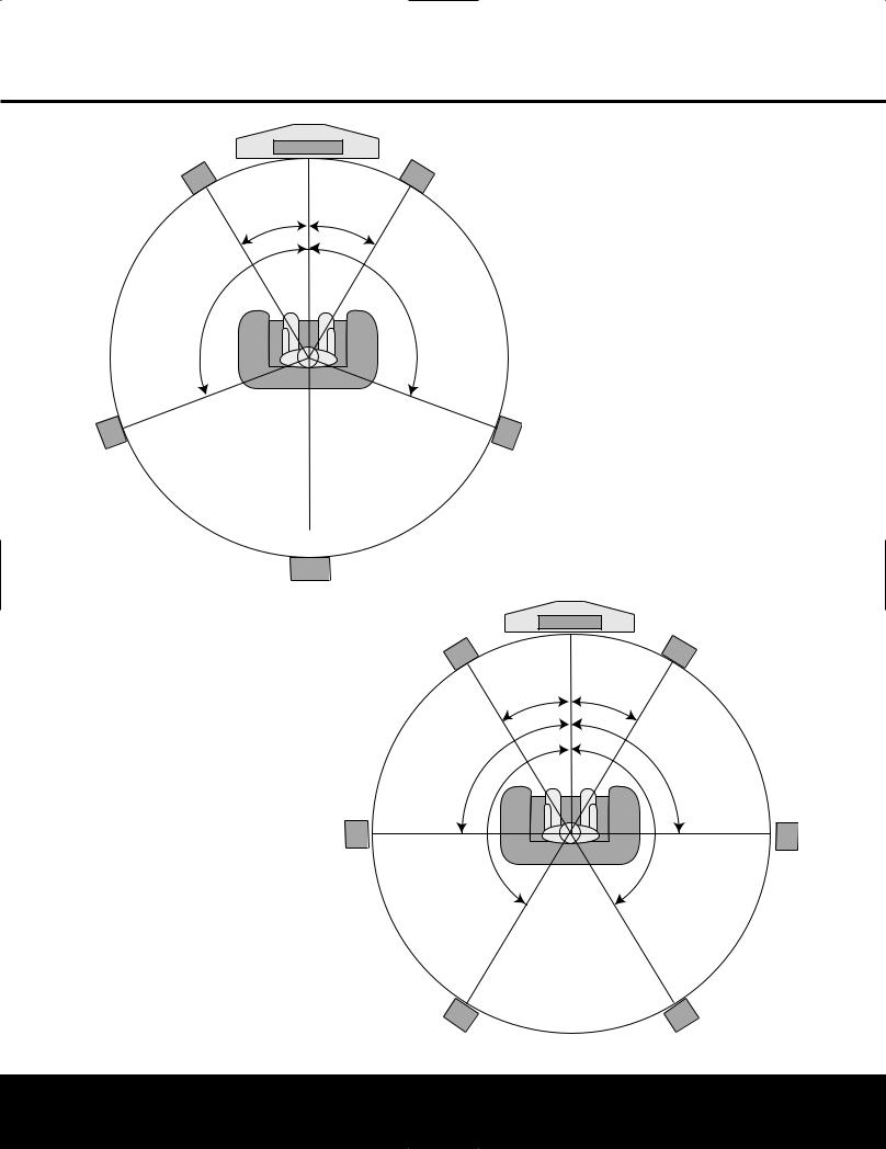
SYSTEM CONFIGURATION
6.1-Channel System |
Center Speaker |
|
V |
|
|
Front Left |
|
Front Right |
Speaker |
|
Speaker |
|
30° |
30° |
110° |
110° |
Side Surround |
Side Surround |
Left Speaker |
Right Speaker |
Back Surround
Speaker
starting on page 26 for manual setup to manually configure your surround back speaker.
We recommend that you consider adding a second surround back speaker as soon as possible.
Surround Speakers for 7.1 Systems
For the ultimate home theater experience, a 7.1 surround system uses both traditional surround left/right channels and a surround back left/right speaker pair. In a 7.1 system, the front left/center/right speakers remain in the same place as they would be for a 5.1 or 6.1 system, but due to the number of speakers involved, the placement of the surround speakers is different.
In a 7.1 system, you should place the main surround left/right speakers at the 90-degree point on our circle. A good way to visualize proper surround speaker positioning for 7.1 is to place the speakers directly to the left and right of the ears of someone sitting in the prime listening spot. The two speakers should ideally face toward each other.
The additional set of Surround Back Left/Right speakers is placed at about 150 degrees on the circle, pointing inward toward the listening area. The easiest way to visualize the placement of these speakers is to place the surround back left speaker directly opposite the right front speaker and to place the surround back left speaker directly opposite the left front speaker.
Surround Speakers for 6.1 Systems
A 6.1 surround speaker adds an additional center back surround speaker to the system, enabling you to enjoy the benefits of advanced surround modes such as Dolby Digital EX, DTS-ES and Harman Kardon’s proprietary Logic 7/7.1 processing.
To step up to a 6.1 system, first place the speakers for a 5.1 system, as shown on page 18. The “sixth” speaker should ideally be placed at the center of the room’s rear wall, pointing directly toward the front center channel speaker.
NOTE: The 6.1-channel configuration is not recommended for the AVR 240. We strongly recommend a 7.1-channel installation as described below. When
6.1-channel materials are played through a 7.1-chan- nel system, the same surround back channel information is played through both the left and right surround back speakers.
If you are only able to install a single surround back speaker at this time, you will not be able to run the full EzSet+ 7.1-channel calibration procedure. In that case, we suggest you install all of your speakers except the surround back speaker, and run the EzSet+ procedure for a 5.1-channel system (see page 24). After EzSet+ has finished, connect the single surround back speaker to the left Surround Back Speaker Outputs 9. Then follow the instructions
|
Video Screen |
7.1-Channel System |
|
Center Speaker |
|
Front Left |
Front Right |
|
Speaker |
|
Speaker |
30° |
30° |
|
90° |
90° |
|
|
1 |
150° |
Side Surround |
Side Surround |
Left Speaker |
Right Speaker |
Back Surround |
Back Surround |
Left Speaker |
Right Speaker |
SYSTEM CONFIGURATION 19
SYSTEM CONFIGURATION
Since subwoofers produce nondirectional sound, they may be placed almost anywhere in a room. Actual placement should be based on room size and shape and the type of subwoofer used. One method of finding the optimal location for a subwoofer is to begin by placing it in the front of the room, about six inches from a wall, or near the front corner of the room. Another method is to temporarily place the subwoofer at your normal listening position, and then walk around the room until you find a spot where the subwoofer sounds best. Place the subwoofer in that spot. You should also follow the instructions of the subwoofer’s manufacturer, or you may wish to experiment with the best location for a subwoofer in your listening room.
NOTES ON SPEAKER PLACEMENT:
1.The limitations of your listening room, including the placement of walls and furniture, may make it difficult to follow the speaker placement suggestions shown above. Depending on the specific layout of the room, here are some ways to compensate for unusual conditions:
•Try to follow the suggested placement, but move the speakers within a few feet from the preferred locations.
•Regardless of where they are placed, always try to make certain that the main surround speakers are the same distance from the front speakers.
(For example, try not to have the right surround speaker further back into the room than the left surround speaker.)
•If it is not possible to wall-mount or place speakers on a shelf, consider the use of optional floor stands, available for many speakers.
2.When using ceiling-mounted in-wall speakers, follow the same guidelines shown for conventional floor or shelf-mounted speakers.
System Setup
Once the speakers have been placed in the room and connected, the remaining steps in the setup process are to configure each source input to match the physical connections you have made, select a surround mode and run the EzSet+ procedure, which will automatically program the AVR 240’s bass management system for the type of speakers used in your system, calibrate the output levels, and set the delay times used by the surround sound processor.
You are now ready to power up the AVR 240 to begin these final adjustments.
1.Make certain that the AC Power Cord fl is firmly inserted into an unswitched AC outlet. To maintain the unit’s safety rating, DO NOT replace the power cord with one that has a lower current capacity.
2.Press the Main Power Switch 1in until it latches and the word “OFF” on the top of the switch disappears inside the front panel. Note that the Power Indicator 2will turn amber, indicating that the unit is in the Standby mode.
3.Remove the protective plastic film from the frontpanel lens. If left in place, the film will affect the performance of your remote control.
4.Install the three supplied AAA batteries in the remote as shown. Be certain to follow the (+) and (–) polarity indicators that are on the top of the battery compartment.
5.Turn the AVR 240 on either by pressing the Standby/On Switch 2on the front panel, or via the remote by pressing the Power On Button d, the AVR Selector for any of the Input Selectors deg. When the unit is turned on, the entire list of options will briefly light for both the Input Indicators Úand the Surround Mode Indicators ˆ. After a few seconds, the majority of those indicators will go dark, leaving only the indications for the active surround mode and input illuminated. The Display Lines Ùı will display the unit’s status, the Power Indicator 2will turn blue, and the accent light inside the Volume Control Òwill also light up to remind you that the unit is turned on.
Using the On-Screen Display
When making the following adjustments, you may find it easier to use the AVR 240’s on-screen display system. These easy-to-read displays give you a clear picture of the current status of the unit and make it easy to see which selection you are making.
To view the on-screen menus, make certain that you have made a connection from the Video or S-Video Monitor Out Jack cV on the rear panel to the composite or S-video input of your TV or projector. In order to view the AVR 240’s displays, the correct video source must be selected on the video display. The on-screen menus are not available when a component video display is in use.
IMPORTANT NOTE: When viewing the on-screen menus using a CRT-based projector, plasma display or any direct-view CRT monitor or television, it is important that they not be left on the screen for an extended period of time. The constant display of a static image such as
these menus or other still images may cause the image to be permanently “burned into” the projection tubes, plasma screen or CRT. This type of damage is not covered by the AVR 240 warranty and may not be covered by the projector/TV set’s warranty.
The AVR 240 has two on-screen display modes, “Semi-OSD” and “Full-OSD.” When making configuration adjustments, it is recommended that the full-OSD mode be used. This will place a menu on the screen, making it easier to view the available options.
Making Configuration Adjustments
The full-OSD system is available by pressing the
OSD Button v. When this button is pressed, the MASTER MENU (Figure 1) will appear, and adjustments are made from the individual menus.
* * M A S T E R M E N U * *
I N P U T S E T U P
A U D I O S E T U P
S U R R O U N D S E L E C T
E z S e t +
M A N U A L S E T U P
A D V A N C E D
Figure 1
The semi-OSD system is also available, allowing you to make adjustments directly, by pressing the appropriate buttons on the front panel or remote control for the specific parameter to be adjusted. For example, to change the digital input for any of the sources, press the Digital Select Button qand then press the ⁄/¤ Buttons nto scroll through the list of options as they appear in the on-screen display or the Upper Display Line P.
To use the full-OSD menu system, press the OSD Button v. When the menu is on the screen, press the ⁄/¤ Buttons nuntil the on-screen › cursor is next to the item you wish to adjust, and then press the Set Button pto adjust that item. The menus will remain on the screen for 20 seconds, and then they will “time-out” and disappear from the screen. The time-out may be increased to as much as 50 seconds by going to the ADVANCED SELECT menu, and changing the item titled FULL OSD TIME OUT (see page 42).
When the full-OSD menu system is used, OSD ON will appear in the Upper Display Line Pto remind you that a video display must be used. When the semi-OSD system is used in conjunction with the discrete configuration buttons, the on-screen display will show the current menu selection. That selection will also be shown in the Upper Display Line P or the Lower Display Line ı, depending on which parameter is being adjusted.
20 SYSTEM CONFIGURATION
 Loading...