


AVR-3550-HD Part 1
harman/kardon
AVR 3550HD
7 X 75W 7.1 CHANNEL A/V RECEIVER
SERVICE MANUAL
CONTENTS
ESD W A R N I N G……………………………….2
LEAKAGE TESTING……………….…..…....3
BASIC SPECIFICATIONS…………………..4
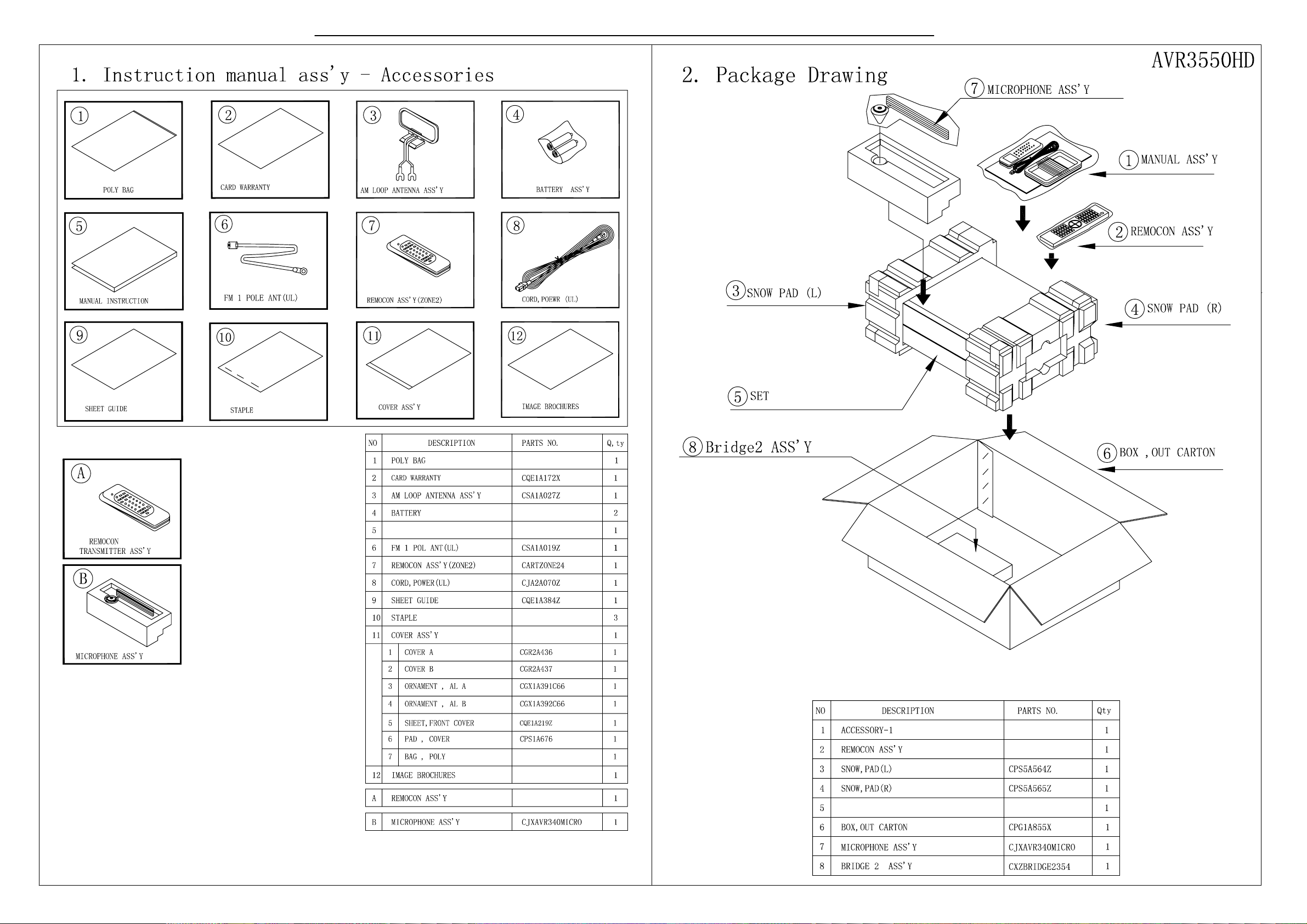
PACKAGING………………………..………..5
FRON T P A NEL CO N T R OLS………..…..…..6
REAR PANEL CONNECTIONS………….…8
REMOTE CONTROL FUNCTIONS.………11
CONNECTIONS………………………….…14
OPERATION………………………...………18
TROUBLESHOOTING GUIDE…...……..…23
PROCESSOR RESET……………….….…..24
DISASSEMBLY………………………………25
UNIT EXPLODED VIEW……………………..26
EXPL O DED VI E W P A RTS LI S T ……………27
AMP BIAS ADJUSTMENT………………….28
BLOCK DIAGRAM…………………….……..29
ELECTRICAL PARTS LIST……….……..…30
PCB DRAWINGS…………………….………72
SEMICONDUCTOR PINOUTS……………..80
SCHEMATICS………………………………199
WIRING DIAGRAM.....................................213
harman/kardon, Inc.
250 Crossways Park Dr.
Released 2008 Woodbury, New York 11797 Rev0 12/2008
Discontinued XXXX

Each precaution in this manual should be followed during servicing.
Components identified with the IEC symbol in the parts list are special significance to safety. When replacing a component identified with
, use only the replacement parts designated, or parts with the same ratings or resistance, wattage, or voltage that are designated in the
parts list in this manual. Leakage-current or resistance measurements must be made to determine that exposed parts are acceptably
insulated from the supply circuit before retuming the product to the customer.
Some semiconductor (solid state) devices can be damaged easily by static electricity. Such components commonly are called
Electrostatically Sensitive (ES) Devices. Examples of typical ES devices are integrated circuits and some field effect transistors and
semiconductor "chip" components.
The following techniques should be used to help reduce the incidence of component damage caused by static electricity.
1. Immediately before handling any semiconductor component or semiconductor-equipped assembly, drain off any electrostatic charge on
your body by touching a known earth ground. Alternatively, obtain and wear a commercially available discharging wrist strap device,
which should be removed for potential shock reasons prior to applying power to the unit under test.
2. After removing an electrical assembly equipped with ES devices, place the assembly on a conductive surface such as aluminum foil, to
prevent electrostatic charge build-up or exposure of the assembly.
3. Use only a grounded-tip soldering iron to solder or unsolder ES devices.
4. Use only an anti-static solder removal device. Some solder removal devices not classified as "anti-static" can generate electrical charges
sufficient to damage ES devices.
5. Do not use freon-propelled chemicals. These can generate electrical change sufficient to damage ES devices.
6. Do not remove a replacement ES device from its protective package until immediately before you are ready to install it. (Most replacement
ES devices are packaged with leads electrically shorted together by conductive foam, aluminum foil or comparable conductive material.)
7. Immediately before removing the protective material from the leads of a replacement ES device, touch the protective material to the
chassis or circuit assembly into which the device will be installed.
Be sure no power is applied to the chassis or circuit, and observe all other safety precautions.
8. Minimize bodily motions when handling unpackaged replacement ES devices. (Otherwise harmless motion such as the brushing together
or your clothes fabric or the lifting of your foot from a carpeted floor can generate static electricity sufficient to damage an ES devices.
CAUTION :
AVR3550HD harman/kardon
2

SAFETY PRECAUTIONS
The following check should be performed for the continued
protection of the customer and service technician.
LEAKAGE CURRENT CHECK
Measure leakage current to a known earth ground (water
pipe, conduit, etc.) by connecting a leakage current tester
between the earth ground and all exposed metal parts of the
appliance (input/output terminals, screwheads, metal
overlays, control shaft, etc.). Plug the AC line cord of the
appliance directly into a 120V AC 60Hz outlet and turn the
AC power switch on. Any current measured must not exceed
o.5mA.
ANY MEASUREMENTS NOT WITHIN THE LIMITS
OUTLINED ABOVE ARE INDICATIVE OF A
POTENTIAL SHOCK HAZARD AND MUST BE
CORRECTED BEFORE RETURNING THE APPLIANCE
TO THE CUSTOMER.
Device
under
test
Test all
exposed metal
surfaces
Also test with
plug reversed
(Using AC adapter
plug as required)
AC Leakage Test
Leakage
current
tester
Reading should
not be above
0.5mA
Earth
ground
3
AVR3550HD harman/kardon

75
AVR 3550HD TECHNICAL SPECIFICATIONS
Audio Section
Seven-Channel Surround Modes
Power per Individual Channel
Front L & R channels:
75 Watts per channel
@ <0.07% THD, 20Hz–20kHz into 8 ohms
Center channel:
75 Watts @ <0.07% THD, 20Hz–20kHz into 8 ohms
Surround (L & R Side, L & R Back) channels:
75 Watts per channel
@ <0.07% THD, 20Hz–20kHz into 8 ohms
Input Sensitivity/Impedance
Linear (High-Level) 200mV/47k ohms
Signal-to-Noise Ratio (IHF-A) 100dB
Surround System Adjacent Channel Separation
Pro Logic
®
I/ II 40dB
Dolby
®
Digital (AC-3) 55dB
DTS
®
55dB
Frequency Response
@ 1W (+0dB, –3dB) 10Hz –130kHz
High Instantaneous
Current Capability (HCC) ±35 Amps
Transient Intermodulation
Distortion (TIM) Unmeasurable
Slew Rate 40V/µsec
FM Tuner Section
Frequency Range 87.5–108.0MHz
Usable Sensitivity IHF 1.3µV/13.2dBf
Signal-to-Noise Ratio Mono/Stereo 70/68dB
Distortion Mono/Stereo 0.2/0.3%
Stereo Separation 40dB @ 1kHz
Selectivity ±400kHz, 70dB
Image Rejection 80dB
IF Rejection 90dB
AM Tuner Section
Frequency Range 520–1720kHz
Signal-to-Noise Ratio 45dB
Usable Sensitivity Loop 500µV
Distortion 1kHz, 50% Mod 0.8%
Selectivity ±10kHz, 30dB
Video Section
Television Format NTSC
Input Level/Impedance 1Vp-p / 75 ohms
Output Level/Impedance 1Vp-p/75 ohms
Video Frequency Response
(Composite and S-Video) 10Hz–8MHz (–3dB)
Video Frequency Response
(Component Video) 10Hz–100MHz (–3dB)
HDMI
™
Version 1.3a with 10-bit Deep Color
General
Power Requirement AC 120V/60Hz
Power Consumption 118W idle, 890W maximum
(7 channels driven)
Dimensions (Product) (Shipping)
Width 17-5/16 inches (440mm) 21-7/8 inches (555mm)
Height 6-1/2 inches (165mm) 10-1/2 inches (266mm)
Depth 15 inches (382mm) 18-5/16 inches (465mm)
(Product) (Shipping)
Weight 31.5 lb (14.3kg) 36.7 lb (16.7kg)
Depth measurement includes knobs, buttons and terminal connections.
Height measurement includes feet and chassis.
All features and specifications are subject to change without notice.
Harman Kardon and Logic 7 are trademarks of Harman International Industries, Incorporated, registered
in the United States and/or other countries. EzSet/EQ, Designed to Entertain and The Bridge II logo are
trademarks of Harman International Industries, Incorporated.
iPod, iTunes and Apple are trademarks of Apple Inc., registered in the U.S. and other countries. iPod not included.
“Made for iPod” means that an electronic accessory has been designed to connect specifically to iPod and has
been certified by the developer to meet Apple performance standards.Apple is not responsible for the operation
of this device or its compliance with safety and regulatory standards.
A-BUS is a registered trademark of Leisure Tech Electronics Pty Ltd.
Audiovox is a registered trademark of Audiovox Corporation.
Blu-ray Disc is a trademark of the Blu-ray Disc Association.
CEA is a registered trademark of the Consumer Electronics Association.
Cirrus Logic is a registered trademark of Cirrus Logic, Inc.
Dolby, the double-D symbol and Pro Logic are registered trademarks of Dolby Laboratories.
Manufactured under license under U.S. Patent #’s 5,451,942; 5,956,674; 5,974,380; 5,978,762;
6,226,616; 6,487,535; 7,003,467 and other U.S. and worldwide patents issued and pending. DTS, DTS-ES
and DTS Neo:6 are registered trademarks, and DTS 96/24, DTS-HD and DTS-HD Master Audio are trademarks,
of DTS, Inc. © 1996-2007 DTS, Inc. All Rights Reserved.
Faroudja DCDi Cinema is a trademark of Genesis Microchip Inc.
HD-DVD is a trademark of the DVD Format/Logo Licensing Corporation (DVD FLLC).
HDMI, the HDMI logo and High-Definition Multimedia Interface are trademarks or registered trademarks of
HDMI Licensing LLC.
SACD is a trademark of Sony Corporation.
TiVo is a registered trademark of TiVo Inc.
XM and XM Ready are registered trademarks of XM Satellite Radio.
4
AVR3550HD harman/kardon
RB46G00
RB46G00
Owner's Manual
AVR 3550HD
AVR 3550HD
5
AVR3550HD harman/kardon
visit www.harmankardon.com

8
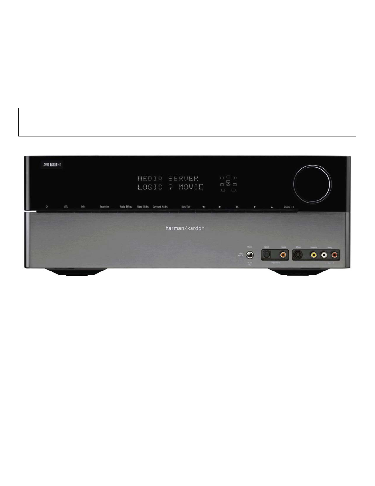
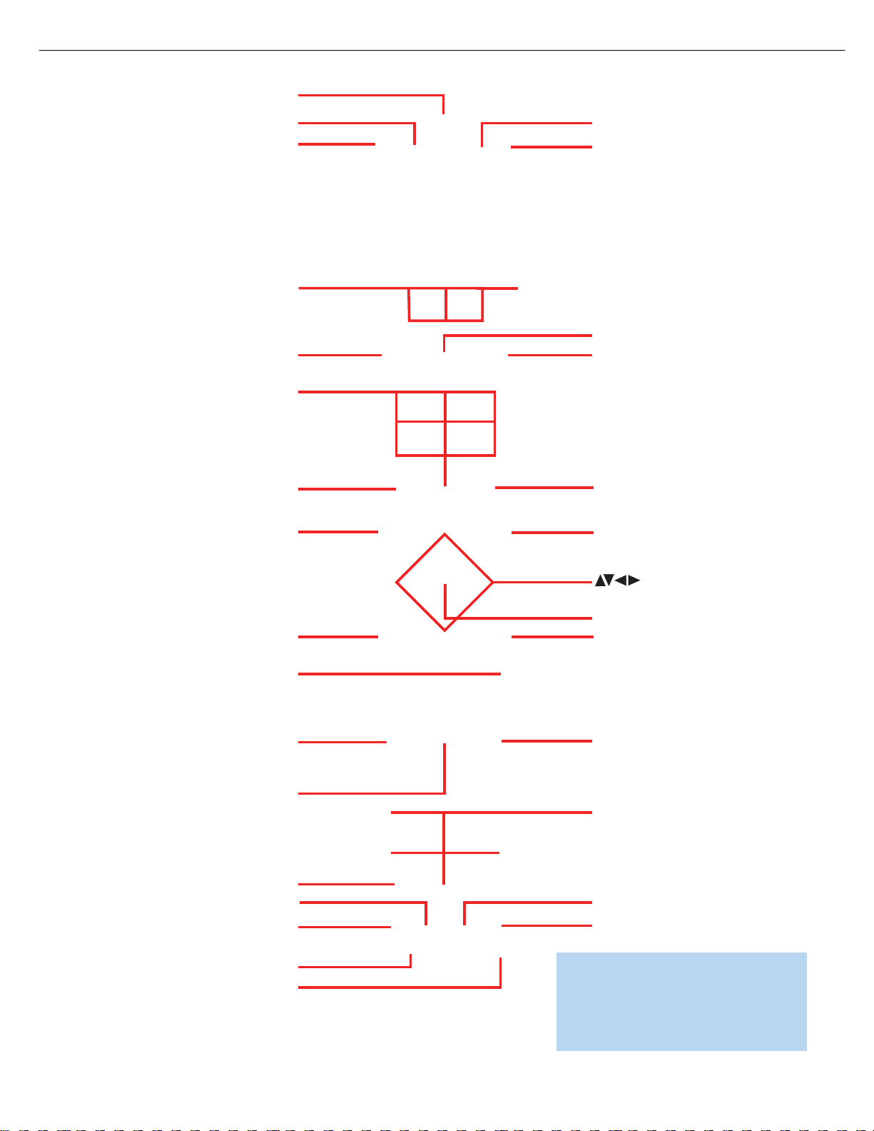
FRONT-PANEL CONTROLS
Standby/On Switch: This electrical switch turns the receiver on
for playback, or leaves it in Standby mode for quick turn-on using this
switch or the remote control.
Power Indicator: This LED has three possible modes:
• Main Power Off: When the AVR is unplugged or the rear-panel
Main Power Switch is off, this LED is off.
• Standby: The LED is amber, indicating that the AVR is ready to
be turned on.
• On: The LED is white, when the AVR is on and operating normally.
NOTE: If the PROTECT message ever appears, turn off the AVR
and unplug it. Check all speaker wires for a possible short. If
none is found, bring the unit to an authorized Harman Kardon
service center for inspection and repair before using it again.
Source List: Press this button to select a source device, which
is a component where a playback signal originates, such as DVD,
cable TV, satellite or the tuner.
Volume Knob: Turn this knob to raise or lower the volume.
Message Display: Various messages appear in this two-line display
in response to commands and changes in the incoming signal. In normal
operation, the current source name appears on the upper line, while
the surround mode is displayed on the lower line. When the on-screen
display menu system (OSD) is in use, the current menu settings appear.
Headphone Jack/EzSet/EQ Microphone Input: Plug a 1/4"
headphone plug into this jack for private listening.
This jack is also used to connect the supplied microphone for the
EzSet/EQ procedure described in the Initial Setup section. To begin
EzSet/EQ, plug the supplied microphone into this jack, place the micro-
phone at the listening position, and follow the directions given in the
Speaker Setup-Automatic Setup-EzSet/EQ on-screen menu.
Surround Modes: Press this button to select a surround sound
(e.g., multichannel) mode. The Surround Modes menu will appear on
screen, and the menu line will appear in the front-panel display.
Use the front-panel or remote
⁄
/
¤
Buttons to highlight a different
menu line: Auto Select, Virtual Surround, Stereo, Movie, Music or Video
Game. Each line represents a type of audio signal, and is set to the
preferred surround mode that you manually select.
Press the OK Button when the menu line is highlighted, and the
available surround mode options for the current signal will appear.
Use the
⁄
/
¤
Buttons to select the desired mode, and press
the OK Button to engage it. Press the Back/Exit Button to exit the
Surround Modes menu.
See the Advanced Functions section for more information on
surround modes.
Analog Audio, Video and Digital Audio Front Inputs: Connect
a source component that will only be used temporarily, such as a digital
camera or game console, to these jacks. Use only one type of audio
and one type of video connection.
NOTES:
• Each of these connections (analog audio, digital audio and
video) may be independently assigned to any source. See the
Initial Setup section for information on setting up sources,
including assigning audio and video inputs to a source.
• The AVR’s menus refer to these jacks as the Optical Front,
Coaxial Front, Composite Front, S-Video Front and Analog
Front inputs.
Speaker/Channel Input Indicators: The box icons indicate
which speaker positions you have configured (see the Initial Setup
Section), and the size (frequency range) of each speaker. The letters
will light inside the boxes to indicate which channels are present in
the incoming signal.
Navigation: These buttons are used to navigate the AVR’s menus
and to operate the tuner.
Remote IR Sensor: This sensor receives infrared (IR) commands
from the remote control. It is important to ensure that it is not blocked.
If covering the sensor is unavoidable, such as when the AVR 3550HD
is placed inside a cabinet, you may use an optional Harman Kardon
HE 1000, or other infrared receiver, connecting it to the Remote IR
Input on the AVR 3550HD’s rear panel. Alternatively, connect the Remote
IR Output of another compatible component to the AVR 3550HD’s
Remote IR Input. Point the remote at the other device’s remote sensor,
and the command will be transmitted to the AVR 3550HD. An external
IR “blaster” may also be used, positioned to point at this area.
AVR Settings Button: Press this button to access the AVR’s
main menu.
Info Settings Button: Press this button to directly access the
AVR’s Source Info submenu, which contains the settings for the
current source.
Resolution: Each press of this button changes the AVR’s video output
resolution to these settings: 480i, 480p, 720p, 1080i or 1080p.
IMPORTANT NOTE: If the AVR’s video output resolution is set
higher than the capabilities of the actual connection, you will not
see a picture. If the best video connection from the AVR to the
TV is either composite or S-video, press this button until the
resolution is set to 480i.
Audio Effects: Press this button to directly access the Audio Effects
submenu, which allows adjustment of the tone and other controls.
See the Initial Setup section for more information.
Video Modes: Press this button for direct access to the Video Modes
submenu, which contains settings that may be used to improve the
picture if necessary after you have adjusted the picture settings using
the video display or TV.
OK: Press this button to select the currently highlighted item.
Back/Exit: Press this button to return to the previous menu, or
to exit the menu system.
6
AVR3550HD harman/kardon
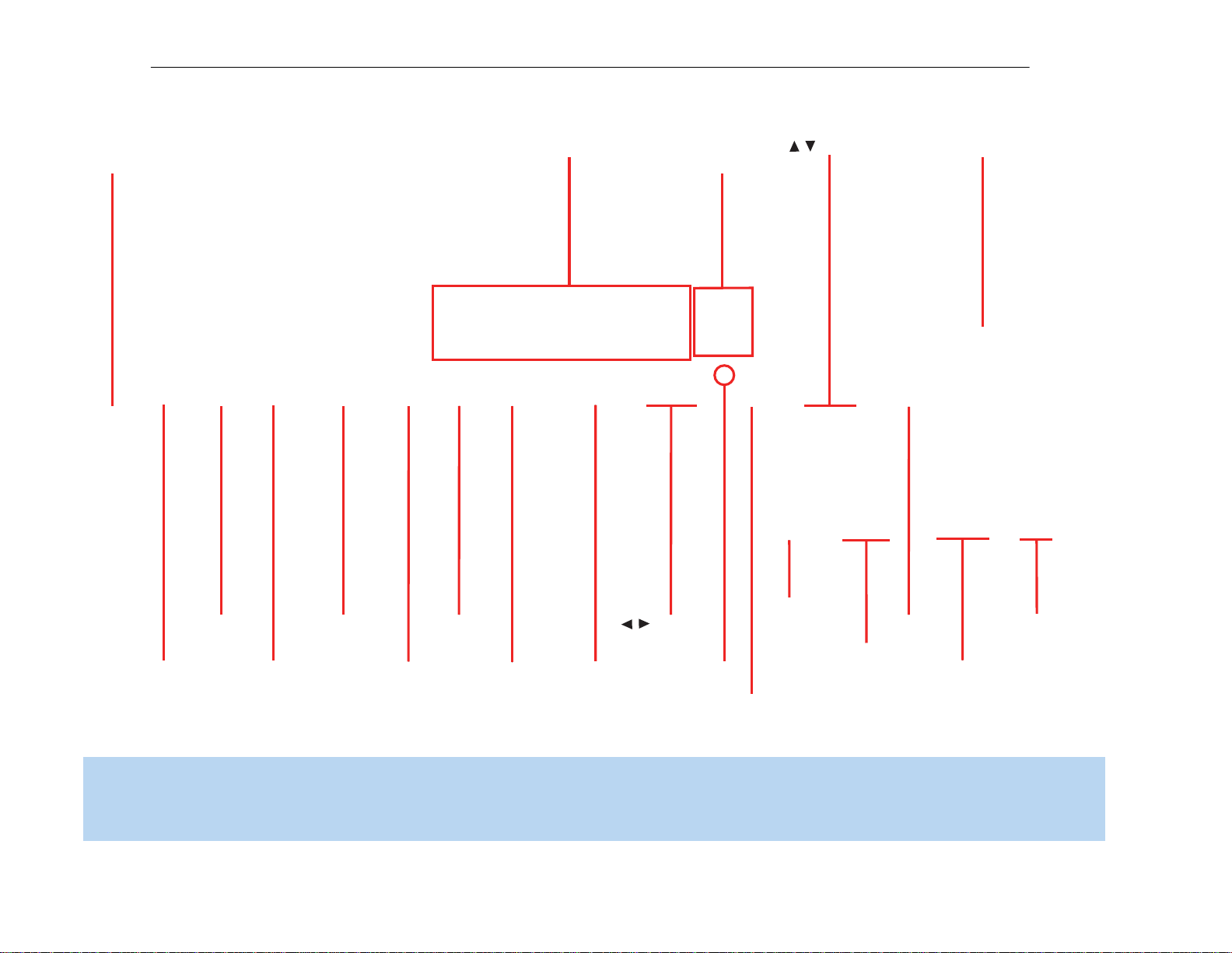
Resolution Navigation
Video
Modes
Source List
Back/Exit
OK
Navigation
Headphone
Jack/EzSet/EQ
Microphone
Input
Digital
Audio Inputs
(Optical and
Coaxial Front)
Remote
IR Sensor
Video Front
Inputs
Analog Audio
Front Inputs
Surround
Modes
Audio
Effects
AVR
Settings
Standby/On
Switch
Info
Settings
Volume
Message DisplayPower
Indicator
Speaker/Channel
Input Indicators
/
/
NOTE: To make it easier to follow the instructions throughout the manual that refer to this illustration, a copy of this page may be downloaded from the Product Support section at
www.harmankardon.com.
7
AVR3550HD harman/kardon

10
REAR-PANEL CONNECTIONS
Main Power Switch: This mechanical switch turns the power supply
on or off. It is usually left in the up position (On), and cannot be turned
on using the remote control.
AM and FM Antenna Terminals: Connect the included AM
and FM antennas to their respective terminals for radio reception.
XM Antenna Jack: Plug in an XM Connect-and-Play or Mini-Tuner
antenna module here. The XM antenna module is purchased separately,
and should specify that it is for home use with an XM Ready
®
product.
You will need to subscribe to the XM service, which is available sepa-
rately, and activate the service for your antenna module. (XM service
is not available in Alaska and Hawaii.)
Front, Center and Surround Speaker Outputs: Use two-
conductor speaker wire to connect each set of terminals to the correct
speaker. Remember to observe the correct polarity (positive and negative
connections). Always connect the positive lead to the colored terminal
on the receiver and the red terminal on the speaker. Connect the negative
lead to the black terminal on both the receiver and the speaker. See the
Connections section for more information on connecting your speakers.
Surround Back/Zone 2 Speaker Outputs: These speaker
outputs are used for the surround back channels in a 7.1-channel home
theater, or may be reassigned to a remote room for multizone operation.
When these outputs are reassigned for multizone operation, only a
5.1-channel configuration will be available in the main listening room.
Use the on-screen menu system to configure these channels as desired.
As with the other speaker outputs, remember to observe proper
polarity by connecting the positive and negative output terminals to
the corresponding terminals on each speaker.
Subwoofer Output: If you have a powered subwoofer with a
line-level input, connect it to this jack.
Preamp Outputs: Connect these jacks to an external amplifier if
more power is desired.
The Surround Back/Zone 2 Preamp Outputs may be used with an
external amplifier to power the surround back channels, or to power
the remote zone of a multizone system. Use the on-screen menu
system to configure these channels as desired.
Remote Infrared (IR) Input and Output: When the remote IR
receiver on the front panel is blocked, such as when the AVR is placed
inside a cabinet, connect an optional IR receiver to the Remote IR Input
jack for use with the remote control. The Remote IR Output may be
connected to the Remote IR Input of a compatible product to enable
remote control through the AVR. This is particularly useful in multizone
applications to control a source device from the remote room (when
used with the Zone 2 IR Input). When several source devices are used,
connect them in “daisy chain” fashion.
Zone 2 Infrared (IR) Input: Connect a remote IR receiver located
in the remote zone of a multizone system to this jack to control the AVR
(and any source devices connected to the Remote IR Output) from the
remote zone.
Remote IR Carrier Output: This output is similar in function to
the Remote IR Output, with the difference that this jack outputs the full
infrared signal as received by the AVR’s IR sensor or the Remote IR
Input, while the Remote IR Output jack outputs a “stripped” signal that
has no carrier frequency. The full signal may be required by some
components with IR inputs. It may also be required when you connect
external IR emitters or other devices to the AVR to pass IR signals to
other components.
A-BUS IR Output: This is an additional IR output that may only be
controlled through the A-BUS system. Use it as a dedicated connection
to sources used only with the A-BUS system, or if the other IR outputs
are in use for incompatible applications.
A-BUS Port: Use a Category 5/5e cable to connect this port to
optional A-BUS equipment for multizone operation. When the A-BUS
system is used, it is possible to have a full 7.1-channel system in the
main listening room at the same time the multizone system is in use.
Composite and S-Video 1, 2 and 3 Video Inputs: These
jacks may be used to connect your video-capable source components
(e.g., VCR, DVD player, cable TV box) to the receiver. Use only one type
of video connection for each source. These inputs are assignable, which
means they may be paired with any analog or digital audio inputs. This
will be explained in more detail in subsequent sections of this manual.
NOTE: The Video 2 inputs are associated with a set of outputs.
Consider connecting a video recorder here.
Composite and S-Video 2 Outputs: Connect one of these
analog video outputs to the composite or S-video inputs of a recording
device. A signal is available at these outputs whenever an analog video
source is playing. HDMI and component video signals are not available
for recording.
Composite and S-Video Monitor Outputs: If any of your
sources use composite or S-video connections, connect one or both of
these monitor outputs to the corresponding inputs on your television or
video display. If your video display is equipped with HDMI or component
video inputs, these connections are unnecessary. Connect the HDMI
Monitor Output (if available, otherwise use the Component Video Monitor
Output) to your TV, and the AVR 3550HD will convert the composite
or S-video source signal to the correct format for a single video cable
connection to the TV.
HDMI Inputs and Output: HDMI (High-Definition Multimedia
Interface) is a connection for transmitting digital audio and video signals
between devices. With the AVR 3550HD’s powerful processor, you may
connect up to three HDMI-equipped source devices to the HDMI inputs
using a single-cable connection, while benefiting from superior digital
audio and video performance. If your video display is not HDMI-compatible,
connect the device to one of the analog video inputs, then pair it with
an analog or digital audio input.
If your video display has an HDMI input, make just the HDMI video con-
nection to your display; the AVR 3550HD will automatically transcode
analog video signals to the HDMI format, upscaling to as high as 1080p.
8
AVR3550HD harman/kardon
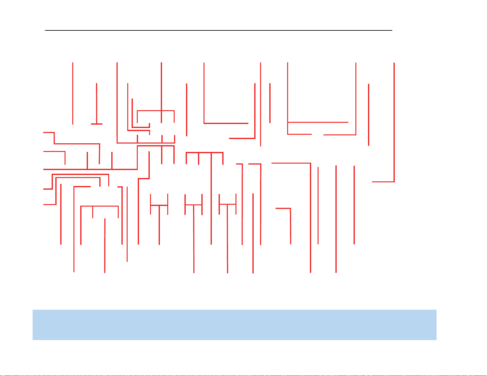
FM Antenna
XM
Antenna
AM Antenna
S-Video 2
Output
Composite 2
Output
Composite
1, 2 and 3
S-Video
1, 2 and 3
Video
Monitor
Outputs
HDMI
1, 2 and 3
AC Power
Input
Main Power
Switch
Component
1, 2 and 3
The Bridge II
HDMI
Monitor
Output
Component Video
Monitor Outputs
Subwoofer
Output
Preamp
Outputs
Front Speaker
Outputs
Surround
Speaker
Outputs
6-/8-
Channel
Inputs
Surround
Back/Zone 2
Speaker Outputs
Center Speaker
Outputs
Switched AC
Accessory
Outlet
RS-232
Reset
RS-232
Serial Port
Coaxial
Digital
Audio
Output
Coaxial
1 and 2
Digital
Audio
Optical 1, 2 and 3
Digital Audio
A
nalog 1–5
Inputs
Carrier
IR Output
Zone 2
IR Input
A-BUS
IR Output
A-BUS
Port
Remote
IR Output
Remote
IR Input
Analog 2
Outputs
Zone 2
Audio
Outputs
Analog 4
Outputs
RS-232
Mode
NOTE: To make it easier to follow the instructions throughout the manual that refer to this illustration, a copy of this page may be downloaded from the Product Support section at
www.harmankardon.com. All connectors are inputs except as indicated.
9
AVR3550HD harman/kardon

12
12
12
12
REAR-PANEL CONNECTIONS
Analog 1– 5: Connect the left and right analog audio outputs of
a source device to any of these inputs. These inputs are assignable,
which means they may be paired with any video inputs, as explained
in subsequent sections of this manual.
NOTES:
• The Analog 3 through 5 connectors physically line up below
the Video 1 through 3 (composite and S-video) connectors.
For convenience, consider using Analog 3 with Video 1, Analog 4
with Video 2 and Analog 5 with Video 3, if appropriate for
your system.
• The Analog 1 and 2 connectors don’t physically line up with
any analog video inputs. Consider using them for audio-only
devices, such as a CD player or cassette tape deck.
• The Analog 2 and 4 inputs are each associated with a set of
outputs. Consider using the Analog 2 connectors for an audio
recorder, and the Analog 4 connectors for a video recorder
(along with the Video 2 connectors).
• You may optionally connect a source to both an analog and
digital audio input. This is useful for making recordings, for
multizone applications or simply as a backup.
Analog 2 and 4 Outputs: Connect either of these analog audio
outputs to the analog audio inputs of a recording device. A signal is
available at these outputs whenever an analog audio source is playing.
However, the AVR 3550HD does not convert digital audio sources to
analog for recording.
Coaxial 1/2 and Optical 1/ 2/3 Digital Audio Inputs: If a
source has a compatible digital audio output, and if you are not using
an HDMI connection for audio for the device, connect it to one of these
jacks to hear digital audio formats, such as Dolby Digital, DTS and linear
PCM. Use only one type of digital audio connection for each source.
Coaxial Digital Audio Output: If a source is also an audio
recorder, connect a coaxial digital audio output to the recorder’s input
for improved recording quality. Only PCM digital audio signals are
available for recording. The AVR 3550HD will pass signals from the
Optical Digital Audio Inputs to this output.
The Bridge II Input: Connect the included Harman Kardon
docking station to this input for use with most docking
iPod models, 4G and later (not included). Make sure the receiver is
turned off (in Standby mode) when connecting The Bridge II.
6-/8-Channel Inputs: Connect the multichannel analog audio
outputs of a DVD-Audio, SACD
™
, Blu-ray Disc
™
or HD-DVD player
(or any other external decoder) to these jacks to enjoy these formats.
NOTE: When the multichannel player has an onboard digital
decoder, it is not necessary to connect it to the 6-/8-Channel
Analog Audio Inputs. Only a digital audio connection (HDMI,
coaxial or optical) is needed.
Zone 2 Audio Outputs: Connect these jacks to an external amplifier
to power the speakers in the remote zone of a multizone system. When
these jacks are used, it is possible to have a full 7.1-channel system in
the main listening room at the same time the multizone system is in use.
Component Video 1, 2 and 3 Inputs: If a video source (e.g.,
DVD player or HDTV tuner) has analog component video (Y/Pb/Pr)
capability, and if you are not using an HDMI connection for the device,
then connect the component video outputs of the source to one of the
sets of component video inputs. Do not make any other video connec-
tions to that source.
Component Video Monitor Outputs: If you are using one of
the Component Video Inputs and your television or video display is
component-video-capable, and if you are not connecting the HDMI
Output to your display, connect these jacks to the corresponding inputs
on your video display.
NOTES:
• Due to copy-protection restrictions, there is no output at the
Component Video Monitor Outputs for copy-protected sources.
• Composite and S-video signals are upscaled to as high as
1080i and available at these outputs. If your video display’s
best connection is component video, it is the only video
connection required from the AVR to the display.
RS-232 Serial Port: This specialized connector may be used with
your personal computer in case we offer a software upgrade for the
receiver at some time in the future.
RS-232 Mode: Leave this switch popped out in the Operate position
unless the AVR 3550HD is being upgraded.
RS-232 Reset: This switch is only used during a software upgrade.
A standard processor reset is performed by pressing and holding the
front-panel OK Button.
Switched AC Accessory Outlet: You may plug the AC power
cord of one source device into this outlet, and it will turn on whenever
you turn on the receiver. Do not use a source that consumes more than
50 watts of power.
AC Power Input: After you have made all other connections, plug the
AC power cord into this receptacle and into an unswitched wall outlet.
10
AVR3550HD harman/kardon

13
13
MAIN REMOTE CONTROL FUNCTIONS
The AVR 3550HD remote is capable of controlling 7 devices, including
the AVR itself and an iPod docked in the included The Bridge II. During
the installation process, you may program the codes for each of your
source components into the remote. Each time you wish to use the
codes for any component, first press its Selector button. This changes
the button functions to the appropriate codes.
Each Source Selector has been preprogrammed to control certain types
of components, with only the codes specific to each brand and model
changing, depending on which product code is programmed. The AUX
Source Selector may be used for any of five device types: a CD player,
an HDTV set-top box, a PVD recorder used with cable or satellite televi-
sion, a TiVo
®
set-top box or a VCR. The device mode will depend
on the product code programmed into the AUX Source Selector as
described in the Initial Setup section. CD players use codes beginning
with a 0, 1 or 2; VCRs use codes beginning with a 3 or 4; HDTV
set-top boxes use codes beginning with a 6; PVDs use codes beginning
with a 7 and TiVo set-top boxes use codes beginning with an 8.
The remote automatically switches to the correct device mode, and
it will operate the device as described in the function list in Table A13
in the appendix.
Similarly, the CBL/SAT Source Selector automatically selects cable or
satellite television operation depending on the first digit of the product
code: 0, 1 or 2 for cable and 3 or 4 for satellite boxes.
IMPORTANT NOTE: All of the AVR 3550HD’s audio and video
inputs are independently assignable. As explained in the Initial
Setup section, it is necessary to set up each source, which
includes selecting the inputs to which the device is physically
connected. Any device may be connected to any compatible
input and given any name (e.g., DVD or Game). The Source
Selectors’ device types may be changed. For example, the TV
Source Selector may be reprogrammed to operate a DVD player.
Most of the buttons on the remote have dedicated functions, although the
precise codes transmitted will vary depending on which source device
has been selected for operation. Due to the wide variety of functions
unique to various source devices, we have included only a few of the most-
often used functions on the remote, including alphanumeric keys, transport
controls, television-channel control, menu access and power on and off.
Please refer to the descriptions below for more specific information.
Some buttons are only used to operate the AVR, and their functions are
available at any time, even if the remote has been switched to another
device’s mode: AVR Power On and Off, Audio Effects, Video Modes,
Surround Modes, Volume, Mute and Sleep Settings. Press the AVR
Settings button near the bottom of the remote to return it to AVR mode.
Any given button may have different functions, depending on which
component is being controlled. Some buttons are labeled with these
functions. For example, the Page Up/Down Buttons are labeled for use
as Channel Up/Down Buttons when controlling a television or cable box.
See Table A13 in the appendix for listings of the different functions for
each type of component.
IR Transmitter Lens: As buttons are pressed on the remote,
infrared codes are emitted through this lens. Make sure it is pointing
toward the component being operated.
AVR Power On Button: Press this button to turn on the AVR. The
Master Power Switch on the AVR 3550HD’s rear panel must first have
been switched on.
Device Power Off Button: When the remote has been switched
to a device’s mode by pressing its Source Selector, press this button to
turn off the device.
Device Power On Button: When the remote has been switched
to a device’s mode by pressing its Source Selector, press this button to
turn on the device.
Mute Button: Press this button to mute the AVR 3550HD’s speaker
and headphone outputs temporarily. To end the muting, press this button
or adjust the volume. Muting is also canceled when the receiver is
turned off.
AVR Power Off Button: Press this button to turn off the AVR 3550HD.
Source Selectors: Press one of these buttons to select a source
device, which is a component where a playback signal originates, e.g.,
DVD, CD, cable TV, satellite or HDTV tuner. This will also turn on the
receiver and switch the remote’s mode to operate the source device.
The first press of the Radio Selector switches the AVR to the last-used
tuner band (AM, FM or XM). Each successive press changes the band.
Audio Effects: This button is only used to operate the AVR. Press it
to directly access the Audio Effects submenu, which allows adjustment
of the tone and other controls. Each successive press scrolls to the next
line in the menu. See the Initial Setup section for more information.
Video Modes: This button is only used to operate the AVR. Press it
for direct access to the Video Modes submenu, which contains settings
that may be used to improve the picture if necessary after you have
adjusted the picture settings using the video display or TV. Each succes-
sive press scrolls to the next line in the menu. See the Advanced
Functions section for more information.
Surround Modes: This button is only used to operate the AVR. Press
it to directly access the Surround Modes submenu. Each successive
press scrolls to the next line in the menu, or use the
⁄
/
¤
Buttons
to scroll to the next line: Auto Select, Virtual Surround, Stereo, Movie,
Music or Video Game. Each menu line represents a type of audio signal,
and is set to the preferred surround mode that you manually select.
Press the OK Button when the menu line is highlighted, and the avail-
able surround mode options for the current signal will appear. Use the
⁄
/
¤
Buttons to select the desired mode, and press the OK Button
to engage it. Press the Back/Exit Button to exit the Surround Modes
menu and display the next higher menu in the hierarchy.
See the Advanced Functions section for more information on surround
modes.
Sleep Settings Button: Press this button to activate the sleep timer,
which turns off the receiver after a programmed period of time of up to
90 minutes. Each successive press increases the timer by 10 minutes,
ending with the “Sleep Off” message.
11
AVR3550HD harman/kardon

14
14
MAIN REMOTE CONTROL FUNCTIONS
Volume Control: Press this button to raise or lower the volume.
Navigation (
⁄
/
¤
/
‹
/
›
) and OK Buttons: These buttons are
used to make selections within the menu system. These buttons are
also used to operate the tuner.
Alphanumeric Keys: Use these buttons to enter numbers for
radio station frequencies or to select station presets. Use the alphabetic
keys with other products as required. When prompted for a text entry,
the first press of the key displays the first letter printed above the key.
Each additional press displays the other letters. When the desired
letter appears, wait a moment for it to be entered before moving to
the next character.
Last Channel: When controlling a cable, satellite or HDTV set-top
box or a TV, press this button to return to the previous television channel.
Activity: This button may be programmed to transmit a series of
commands with a single press, which is useful for powering on all
devices and selecting the correct settings on each device, or for selecting
multidigit channels. After a string of commands has been programmed
into an Activity, execute it by pressing this button, then the Alphanumeric
Key (or the AVR Power On Button) into which the Activity was programmed.
See the Advanced Functions section for more information on Activities.
Back/Exit: Press this button to return to the previous menu or to exit
the menu system. This button may have the same effect with some
source devices.
Menu Button: This button is used to display the main menu on some
source devices. To display the AVR 3550HD’s main menu, press the
AVR Settings Button.
Disc Menu: While a DVD is playing, press the DVD Source Selector,
then this button, to display the disc’s menu.
Teletext Buttons: Use these buttons with a Teletext-capable televi-
sion if your broadcast, cable or satellite provider offers Teletext service.
They are normally not used in North America. These buttons are also
used to operate some source devices. See Table A13 in the appendix
for details.
Channel/Page Control: When the tuner has been selected, this
control selects a preset radio station. Press these buttons while operat-
ing a cable, satellite or HDTV set-top box or a television to change
channels. The Page control may be available with some DVD players
when playing a DVD Audio disc containing pages of images associated
with a track.
Record Button: Use this button to make recordings when an audio
or video recorder is in use.
AVR Settings Button: Press this button to display the AVR’s Main
Menu. It is also used to switch the remote’s device mode from a source
device to the AVR.
Info Settings Button: Press this button to display the AVR’s Info
Menu, which contains the settings for the current source.
Source Settings Button: Press a Source Selector and then this
button to display a source device’s settings menu.
Zone Selector: Use this switch to select whether AVR commands
will affect the main listening area (Zone 1) or the remote zone of a
multizone system (Zone 2). For normal operation, leave the switch in
the Zone 1 position.
Track Skip: These buttons have no effect on the receiver, but are
used with source components to change tracks or chapters.
Transport Controls: These buttons have no effect on the receiver,
but are used to control many source components.
Light: Press this button to illuminate the buttons on the remote. Press
it again to turn the backlight off, or wait ten seconds after the last button
press for the light to turn off on its own.
Learn: The AVR 3550HD remote is capable of “learning” individual
IR codes from the original remote that came with your TV or a device
that is connected to any of the source inputs. See Step Eight of the
Installation section for instructions on learning remote codes.
12
AVR3550HD harman/kardon
AVR Power Off
AVR Power On
Source Selectors
Audio Effects
Alphanumeric Keys
Teletext
Volume
Mute
Device Power On
Device Power Off
Surround Modes
Video Modes
OK
Navigation
Activity
Menu
Disc Menu
Channel/Page
Sleep Settings
Learn
Transport Controls
Source Settings
IR Transmitter Lens
Last
Back/Exit
Light
Record
Info Settings
AVR Settings
Zone Selector
15
NOTE: To make it easier to follow the
instructions throughout the manual that refer
to this illustration, a copy of this page may
be downloaded from the Product Support
section at www.harmankardon.com.
13
AVR3550HD harman/kardon
19
There are different types of audio and video connections used to
connect the receiver to the speakers and video display, and to connect
the source devices to the receiver. To make it easier to keep them all
straight, the Consumer Electronics Association has established the
CEA
®
color-coding standard. See Table 1.
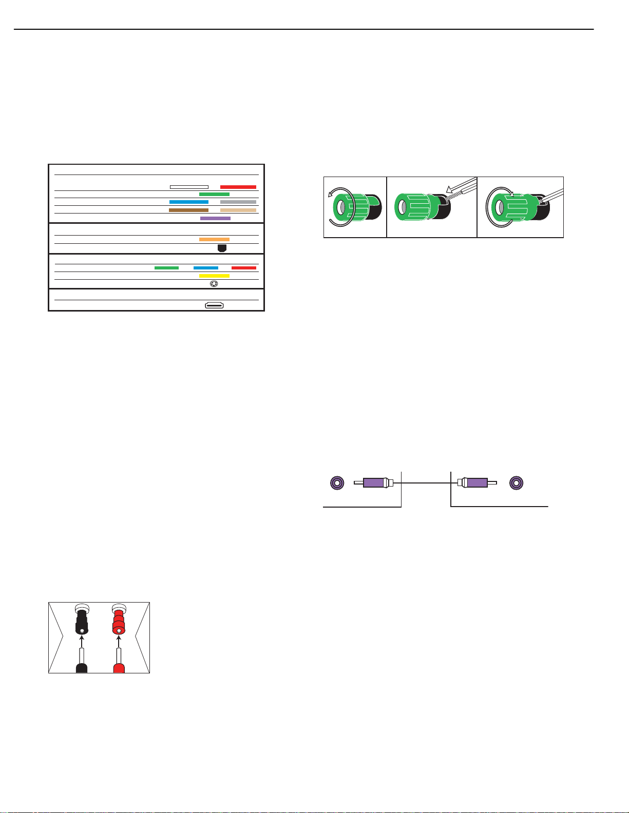
Table 1 – Connection Color Guide
Types of Connections
This section will briefly review different types of cables and connections.
Speaker Connections
Speaker cables carry an amplified signal from the receiver’s speaker
terminals to each loudspeaker. Speaker cables contain two wire conduc-
tors, or leads, inside plastic insulation. The two conductors are usually
differentiated in some way, by using different colors, or stripes, or by
adding a ridge to the insulation. Sometimes the wires are different,
colors e.g. copper-colored and silver.
The differentiation is important because each speaker must be connected
to the receiver’s speaker-output terminals using two wires, one positive
(+) and one negative (–), referred to as speaker polarity. It’s important
to maintain the proper polarity for all speakers in the system, or perform-
ance can suffer, especially for the low frequencies.
Always connect the positive terminal on the loudspeaker, which is usually
colored red, to the positive terminal on the receiver, which is colored as
shown in the Connection Color Guide (Table 1). Similarly, always connect
the black negative terminal on the speaker to the black negative terminal
on the receiver.
The AVR 3550HD uses binding-post
speaker terminals that can accept banana
plugs or bare-wire cables. Banana plugs
are simply plugged into the hole in the
middle of the terminal cap. See Figure 1.
Figure 1 – Binding-Post Speaker Terminals With Banana Plugs
Bare wire cables are installed as follows (see Figure 2):
1. Unscrew the terminal cap until the pass-through hole in the collar is
revealed.
2. Insert the bare end of the wire into the hole.
3. Hand-tighten the cap until the wire is held snugly.
Figure 2 – Binding-Post Speaker Terminals With Bare Wires
Subwoofer
The subwoofer is a specialized type of loudspeaker used to play only
the low frequencies (bass), which require much more power than the
other speaker channels. In order to obtain the best results, most speaker
manufacturers offer powered subwoofers, in which the speaker contains
its own amplifier on board. Usually, a line-level (nonamplified) connection
is made from the receiver’s Subwoofer Output to a corresponding jack
on the subwoofer, as shown in Figure 3, but sometimes the subwoofer
is connected to the receiver using the front left and right speaker outputs,
as with passive in-wall subwoofers, and then the front left and right
speakers are connected to terminals on the subwoofer.
Although the subwoofer output looks similar to the analog audio jacks
used for the various components, it is filtered and only allows the low
frequencies to pass. Don’t connect this output to any other devices.
Although doing so won’t cause any harm, performance will suffer.
Figure 3 – Subwoofer
Connecting Source Devices to the AVR
The AVR 3550HD is designed to process audio and video input signals,
playing back the audio and displaying the video on a television or
monitor connected to the AVR. These signals originate in what are
known as “source devices,” including your DVD player, CD player, DVR
(digital video recorder) or other recorder, tape deck, game console,
cable or satellite television box or MP3 player. Although the tuner is
built into the AVR, it also counts as a source, even though no external
connections are needed, other than the FM and AM antennas and the
XM antenna module.
Separate connections are required for the audio and video portions of
the signal, except for digital HDMI connections. The types of connections
used depend upon what’s available on the source device, and for video
signals, the capabilities of your video display.
SubwooferPreout
12 3
+
Audio Connections
Left Right
Front (FL/FR)
Center (C)
Surround (SL/SR)
Surround Back (SBL/SBR)
Subwoofer (SUB)
Digital Audio Connections
Coaxial
Optical
Video Connections
Component Y Pb Pr
Composite
S-Video
HDMI
™
Connections (digital audio/video)
HDMI
Input
CONNECTIONS
14
AVR3550HD harman/kardon

20 20
CONNECTIONS
Audio Connections
There are two formats for audio connections: digital and analog. Digital
audio signals are required for listening to sources encoded with digital
surround modes, such as Dolby Digital and DTS, or for non-compressed
PCM digital audio. There are three types of digital audio connections:
HDMI, coaxial and optical. Any type of digital audio connection may be
used for each source device, but never more than one for the same
source. However, it’s okay to make both analog and digital audio con-
nections to the same source.
NOTE: Since HDMI signals may carry both audio and video, if
your video display device has an HDMI input, make a single HDMI
connection from your source device (such as a DVD player) to
the AVR. No separate digital audio connection is usually required.
Make sure to turn the volume on your television all the way down.
Digital Audio
The AVR 3550HD is equipped with three HDMI (High-Definition
Multimedia Interface) inputs, and one output. HDMI technology enables
digital audio and video information to be carried using a single cable,
thus delivering the highest quality picture and sound.
There are different HDMI versions, depending on the capability of
the source device and the type of signal it is capable of transmitting.
In addition, receivers and processors such as the AVR 3550HD may
handle the incoming signal in several different ways, depending on their
capability as well. The AVR 3550HD uses HDMI (V.1.3 with Deep Color)
technology and is capable of processing both the audio and video
components of the HDMI data, minimizing the number of cable
connections in your system. The AVR 3550HD implements Deep Color,
which increases by an order of magnitude the shades of color that can
be displayed; and the latest lossless multichannel audio formats, including
Dolby TrueHD and DTS-HD Master Audio.
NOTE: Some DVD-Audio, SACD, Blu-ray Disc and HD-DVD
players, output mulitchannel audio only through the source’s
multichannel analog outputs. For those devices, make a sepa-
rate analog audio connection in addition to the HDMI connec-
tion, which is still used for video and to listen to Dolby Digital,
DTS or PCM materials that may be stored on the disc.
In addition, the AVR 3550HD will convert analog video signals to the
HDMI format, upscaling to high-definition 1080p resolution. You may view
the AVR 3550HD’s own on-screen display menus using the HDMI output.
The physical HDMI connection is simple. The connector is shaped for
easy plug-in (see Figure 4). If your video display has a DVI input and is
HDCP-compliant, you may use an HDMI-to-DVI adapter (not included)
to connect it to the AVR’s HDMI Output, but a separate audio connection
is required. HDMI cable runs are usually limited to about 10 feet,
depending on the type of cable used.
Figure 4 – HDMI Connection
If your video display or source device is not HDMI-capable, use one
of the analog video connections (composite, S- or component video)
and, if available on your source device, either a coaxial or optical digital
audio connection.
Coaxial digital audio jacks are usually color-coded in orange. Although
they look similar to analog jacks, they should not be confused, and you
should not connect coaxial digital audio outputs to analog inputs or
vice versa. See Figure 5.
Figure 5 – Coaxial Digital Audio
Optical digital audio connectors are normally covered by a shutter to
protect them from dust. The shutter opens as the cable is inserted. Input
connectors are color-coded using a black shutter, while outputs use a
gray shutter. See Figure 6.
Figure 6 – Optical Digital Audio
Analog Audio
Analog connections require two cables, one for the left channel (white)
and one for the right channel (red). These two cables are often attached
to each other for most of their length. See Figure 7.
Most sources that have digital audio jacks also have analog audio jacks,
although some older types of sources, such as tape decks, only have
analog jacks. For sources that are capable of both digital and analog
audio, you may make both connections.
The analog audio connection is strongly recommended if you intend
to use the source with the multizone system. It’s required if you will be
using the multizone preamp outputs with an external amplifier to power
your remote speakers, as the AVR 3550HD’s multizone system is not
capable of converting the digital signal to analog format. It’s suggested
that you also use the analog audio connections when using the
Surround Back/Zone 2 speaker outputs, in case another two-channel
digital audio source is in use in the main listening area. The AVR 3550HD
is only capable of processing one PCM source at a time.
You may only record materials from DVDs or other copy-protected
sources, using analog connections. Remember to comply with all copy-
right laws, if you choose to make a copy for your own personal use.
Figure 7 – Analog Audio
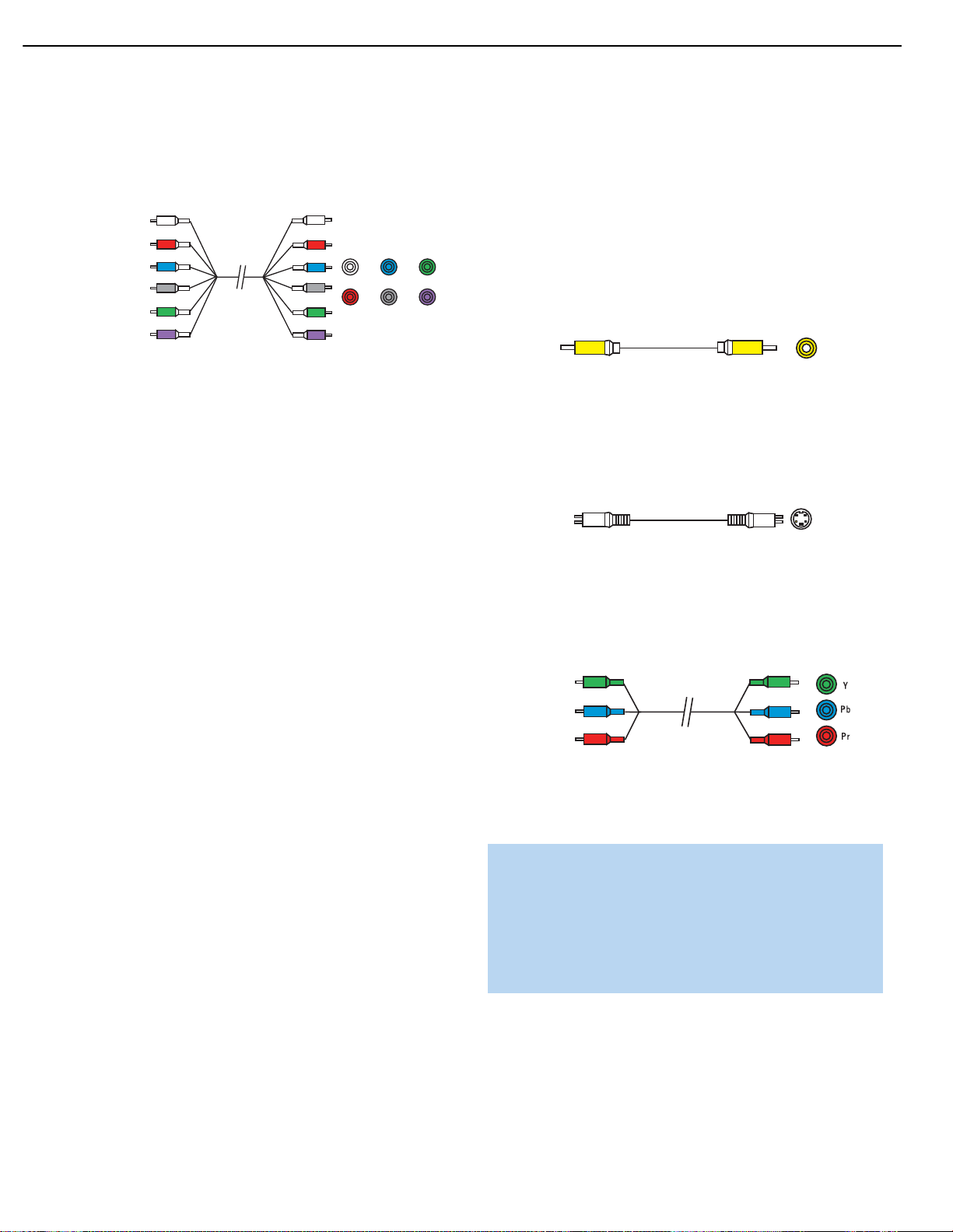
Multichannel analog connections are used with some high-definition
sources where the copy-protected digital content is decoded inside the
source. These types of connections are usually used with DVD-Audio,
SACD, Blu-ray Disc, HD-DVD and other multichannel players. See
Figure 8. However, the multichannel analog audio connection is not
L
R
Analog audio
cable (RCA)
Optical
Optical digital
audio cable
Coaxial
Coaxial digital
audio cable
15
AVR3550HD harman/kardon
21
21
CONNECTIONS
required for DVD-Audio players compliant with HDMI version 1.1 or
better, or HD-DVD and Blu-ray Disc players that decode the digital audio
internally and output linear PCM signals in digital format. Consult the
owner’s guide for your disc player for more information.
Figure 8 – Multichannel Analog Audio
Harman Kardon receivers also include a proprietary, dedicated audio
connection called The Bridge II docking station for iPod. If you own a
docking iPod (most models, 4G or later), connect The Bridge II (included)
to The Bridge II port on the receiver. See Figure 9. Dock your iPod
(not included) in The Bridge II, and you may listen to your audio materials
through your high-performance audio system. You may view still images
or video materials stored on a photo- or video-capable iPod that
supports video browsing. You may even use the AVR 3550HD remote
to control the iPod with navigation messages displayed on the front panel
and on a video display connected to the AVR. The Bridge II outputs analog
audio to the AVR 3550HD, and it is available to the multiroom system.
Figure 9 – The Bridge II port
Video Connections
Although some sources only produce an audio signal (e.g., CD player,
tape deck), many sources output both audio and video signals (e.g.,
DVD player, cable television box, HDTV tuner, satellite box, VCR, DVR).
In addition to the audio connection, make one type of video connection
for each of these sources (only one at a time for any source).
Digital Video
If you have already connected a source device to one of the HDMI
inputs as explained in the Digital Audio Connections section, you have
automatically made a video connection at the same time, as the HDMI
signal includes both digital audio and video components.
If the source device is not capable of transmitting its digital audio signal
through the HDMI connection, use one of the coaxial or optical digital
audio inputs for the source.
If a multichannel analog audio connection is required for certain lossless
formats (e.g., DVD-Audio, SACD, Blu-ray Disc or HD-DVD), you may
make both audio connections. To listen to the multichannel disc, set the
Audio Auto Polling setting to the 6/8CH inputs, and the AVR will automati-
cally select it when no digital signal is output by the player.
Analog Video
There are three types of analog video connections: composite video,
S-video and component video.
Composite video is the basic connection most commonly available. The
jack is usually color-coded yellow, and looks like an analog audio jack,
although it is important never to confuse the two. Do not plug a composite
video cable into an analog or coaxial digital audio jack, or vice versa.
Both the chrominance (color) and luminance (intensity) components of
the video signal are transmitted using a single cable. See Figure 10.
Figure 10 – Composite Video
S-video, or “separate” video, transmits the chrominance and luminance
components using separate wires contained within a single cable. The
plug on an S-video cable contains four metal pins, plus a plastic guide
pin. Be careful to line up the plug correctly when you insert it into the
jack on the receiver, source or video display. See Figure 11.
Figure 11 – S-Video
Component video separates the video signal into three components –
one luminance (“Y”) and two sub-sampled color signals (“Pb” and “Pr”) –
that are transmitted using three separate cables. The “Y” cable is color-
coded green, the “Pb” cable is colored blue and the “Pr” cable is
colored red. See Figure 12.
Figure 12 – Component Video
If it’s available on your video display, an HDMI connection is recom-
mended as the best quality connection, followed by component video,
S-video and then composite video.
NOTES:
• Copy-protected sources are not available at the Component
Video Monitor Outputs.
• Standard and high-definition analog video signals are upscaled
to 1080i resolution for the Component Video Monitor Outputs.
For improved video performance, consider upgrading to an
HDMI-capable video display with 1080p resolution.
Antennas
The AVR 3550HD uses separate terminals for the included FM and AM
antennas that provide proper reception for the tuner.
Component
video cable
S-video cable
Composite
video cable
Multichannel
analog audio
cable (RCA)
Front Surround Center
Subwoofer
16
AVR3550HD harman/kardon

22
The FM antenna uses a 75-ohm F-connector. See Figure 13.
Figure 13 – FM Antenna
The AM loop antenna needs to be assembled. Connect the two leads
to the spring terminals on the receiver. As AM antenna leads have no
polarity, it doesn’t matter which of the two terminals is used for either
lead. See Figure 14.
Figure 14 – AM Antenna
To enjoy XM satellite radio, purchase an XM antenna module designed
for use with XM Ready devices and a subscription to the XM service.
We recommend the XM Mini Tuner and Home Dock Bundle, available
at www.xmradio.com. The older Connect-and-Play module is also
compatible with the AVR 3550HD, but it may no longer be available
in your area.
An XM Ready-compatible module uses the special connector on the
AVR 3550HD’s rear panel that allows you to use the AVR’s tuner,
including its 40 preset station locations and remote control. Although
you may use a module with standard audio connections, which may
be indicated for “car and home use,” you will not be able to enjoy the
AVR 3550HD’s ease of control.
RS-232 Serial Port
The RS-232 serial port on the AVR 3550HD is used only for software
upgrades. If we release an upgrade for the receiver’s operating system
at some time in the future, it may be downloaded to the AVR using this
port. Complete instructions will be provided at that time.
CONNECTIONS
17
AVR3550HD harman/kardon

40
OPERATION
Now that you have installed your system components and completed
a basic configuration of your receiver, you are ready to begin enjoying
your home theater system.
Turning On the AVR 3550HD
Flip the Main Power Switch on the rear panel up to the “ On” position. The
Power Indicator on the front panel should light up in amber. This indicates
that the AVR is in Standby mode and is ready to be turned on. Normally,
you may leave the Main Power Switch on, even when the receiver is not
being used. See Figure 46.
There are several ways in which the AVR 3550HD may be turned on:
a) Press the Standby/On Switch on the front panel. See Figure 46.
b) Using the remote, press the AVR Power On Button or any of the
Source Selectors. See Figure 47.
To turn the receiver off, press either the Standby/On Switch on the front
panel, or press the AVR Power Off Button on the remote. Unless the
receiver will not be used for an extended period of time (for example,
when are on vacation), it is not necessary to turn off the Main Power
Switch. When the Main Power Switch is turned off, any settings you
have programmed, including system configuration and preset radio
stations, will be preserved for up to four weeks.
IMPORTANT NOTE: If the PROTECT message ever appears
in the Message Display, turn off the AVR and unplug it. Check
all speaker wires for a possible short. If none is found, bring
the unit to an authorized Harman Kardon service center for
inspection and repair before using it again.
Volume Control
The volume may be adjusted either by turning the knob on the front
panel (clockwise to increase volume or counterclockwise to decrease
volume), or by pressing the Volume Control on the remote. See Figure 57.
The volume is displayed as a negative number of decibels (dB) below
the 0dB reference point.
Unlike the volume controls on some other products, 0dB is the maximum
volume for the AVR 3550HD. Although it’s physically possible to turn the
volume to a higher level, doing so may damage your hearing and your
speakers. For certain more dynamic audio materials, even 0dB may be
too high, allowing for damage to equipment. We urge caution with
regard to volume levels.
You may change the volume level display from the default decibel scale
to a 0-to-100 scale by adjusting the Volume Units setting in the System
Settings menu, as described on page 55.
Figure 57 – Volume Controls
Mute Function
To temporarily mute all speakers and the headphones, press the Mute
Button on the remote. See Figure 57. Any recording in progress will
not be affected. The MUTE message will appear in the display as a
reminder. To restore normal audio, either press the Mute Button again,
or adjust the volume. Turning off the AVR will also end muting.
Sleep Timer
You may program the AVR to play for up to 90 minutes and then turn
off automatically using the sleep timer.
Press the Sleep Settings Button on the remote, and the time until
turn-off will be displayed. See Figure 58. Each additional press of the
Sleep Button will increase the time until turn-off by 10 minutes, up
to a maximum of 90 minutes, then the SLEEP OFF setting appears,
which disables the sleep timer.
Figure 58 – Sleep Settings Button
When the sleep timer has been set, the front-panel display will automati-
cally dim to half-brightness. If you press any button on the remote or
front panel, the display will return to full-brightness. The display will dim
again several seconds after your last command.
If you press the Sleep Button after the timer has been set, the remaining
time until turn-off will be displayed. You may press the Sleep Button to
change the time until turn-off.
Audio Effects
Depending on your preferences or the specific characteristics of your
listening room, you may wish to adjust some of the audio settings, such
as tone controls, to improve performance. Access these settings from
the Audio Effects submenu, as described in the Advanced Functions
section.
It is not necessary to adjust the Audio Effects settings to enjoy your
new AVR. We recommend leaving the settings at their default values
until you are more familiar with your system.
Video Modes
The settings in the Video Modes menu are used to fine-tune the
picture if necessary after making all adjustments on the video display.
It is recommended that you leave the settings at their defaults. See the
Advanced Functions section for detailed information.
Headphones
Plug the 1/4" plug on a pair of headphones into the headphone
jack on the front of the receiver for private listening. See Figure 59.
18
AVR3550HD harman/kardon

41
OPERATION
The DOLBY H:BYPASS message indicates that Dolby Headphone
surround processing is in the default bypass mode, which delivers
a conventional 2-channel signal to the headphones.
Figure 59 – Headphone Jack
Press the Surround Modes Button on the front panel or the remote, to
switch to Dolby Headphone virtual surround processing, indicated by the
DOLBY H:DH message. Dolby Headphone delivers an enhanced sound
field that emulates a 5.1-channel speaker system. No other surround
modes are available for the headphones.
Source Selection
Press the front-panel Source List Button to scroll through the sources.
Each press of the button scrolls down the list that appears in the display
and on screen. See Figure 60.
Figure 60 – Source List Button
For direct access to any source, press its Source Selector on the remote.
The AVR 3550HD will switch to the audio and video inputs assigned to
the source.
The source name will appear in the upper line of the front-panel display.
If you retitled the source, the new title will appear. The audio and video
inputs assigned to the source will also appear briefly. The surround
mode will be displayed on the lower line.
Any other settings you adjusted in the Setup Source menu will also be
selected. You may view these settings in the Source Info menu at any
time by pressing the Info Settings Button.
VIDEO TROUBLESHOOTING TIPS:
If a video source is playing and there is no picture:
• Check that you have selected the source to which the
video input was assigned.
• Check the wires for a loose or incorrect connection.
• Check that you have selected the correct video input on
the display device (TV).
• Try pressing the Resolution Button on the front panel repeat-
edly until the correct video output resolution is selected and
a picture appears. You will be prompted to accept or cancel
the resolution change, as the CANCEL message will appear
on the front panel. Press the
¤
Button to view the ACCEPT
option, and then press the OK Button to complete the change
to the output resolution.
Additional Tips for Systems Using HDMI:
• Turn off all devices (including the TV, AVR and any source
components).
• Unplug the HDMI cables starting with the cable between the
TV and AVR, and continuing with the cables between the AVR
and each source device.
• Carefully reconnect the cables from the source devices to
the AVR, and connect the cable from the AVR to the TV last.
• Turn on the devices in this order: TV, then AVR, then source
devices.
Using the Tuner
To select the AVR 3550HD’s built-in tuner:
1. Press the Source List Button on the front panel repeatedly until the
desired tuner band is selected, or use the
⁄
/
¤
Buttons to scroll
through the source list.
2. Press the Radio Source Selector on the remote. Press this button
again to switch bands (AM, FM or XM).
A screen similar to the one shown in Figure 61 will appear, with the
band indicated in the middle of the screen. (The XM band uses a slightly
different screen.)
Figure 61 – FM Radio
Use the
⁄
/
¤
Buttons to tune a station (or channel for XM Radio).
The frequencies will be displayed in the front panel and graphically on
screen.
The AVR defaults to automatic tuning, meaning each press of the
⁄
/
¤
Buttons scans through all frequencies until a station with accept-
able signal strength is found. To switch to manual tuning, in which each
press of the
⁄
/
¤
Buttons steps through a single frequency increment
(0.1MHz for FM, or 10kHz for AM), press the Menu Button. The Radio
Modes line will be highlighted, and each press of the OK Button toggles
between automatic and manual tuning modes.
When an FM station has been tuned, toggling the radio mode switches
between stereo and monaural play, which may improve reception of
weaker stations.
A total of 30 stations (AM and FM together) may be stored as presets.
When the desired station has been tuned, press the OK Button, and two
dashes will flash in the front-panel display. Use the Alphanumeric Keys
to enter the desired preset number.
19
AVR3550HD harman/kardon

42
OPERATION
To tune a preset station, press the
‹
/
›
Buttons or the Channel
Control, or press the Menu Button to view the list of programmed pre-
sets and scroll to the desired selection. Press the OK Button to tune the
station. You may also enter the preset number using the Numeric Keys.
For presets 10 through 30 press 0 before the preset number. For
example, to enter preset 21, press 0-2-1.
XM Radio Operation
XM Radio is a satellite-delivered service that offers hundreds of program
channels, as well as local traffic and weather information for select cities.
The AVR 3550HD is an XM Ready device, which means that it is able to
receive the XM service when a user-supplied XM antenna module is
connected and the service activated.
Select an antenna module designated for XM Ready audio components.
An XM Ready-compatible module uses the special connector on the
AVR 3550HD’s rear panel that allows you to use the AVR’s tuner,
including its 40 preset station locations and remote control. Although
you may use a module with standard audio connections, which may be
indicated for “car and home use,” you will not be able to enjoy the AVR
3550HD’s ease of control.
The XM Mini-Tuner and Home Dock (Models CNP-2000 and CNP-2000H;
both pieces are required) are compatible with the AVR 3550HD. The
older Audiovox
®
CNP 1000 “Connect-and-Play” module for home audio
use is also compatible, but has been discontinued and may no longer
be available. Additional modules may become available in the future.
Modules produced for automotive, or “mobile,” use are not compatible
with the AVR 3550HD, although if they have standard analog or digital
audio outputs, they may be connected to a compatible input and oper-
ated using their own controls.
NOTE: To listen to XM Radio using the AVR 3550HD, you will
need to purchase an XM antenna module and subscription, and
activate your module. XM service is not available in Alaska or
Hawaii. Visit the XM Radio Web site at www.xmradio.com for
more information.
Plug the module into the XM Antenna Jack on the rear of the AVR 3550HD.
Place the antenna module so that it has a clear view through a south-
facing window in order to obtain reception from the XM satellite.
Select XM Radio as the source in one of these ways:
1. Press the Source List Button on the front panel repeatedly until
XM Radio is selected, or use the
⁄
/
¤
Buttons to scroll through
the source list.
2. Press the Radio Source Selector on the remote repeatedly until
XM Radio is selected..
You should be able to tune in Channel 1, the Preview Channel, to
confirm that your equipment is ready for activation. There are four
ways to tune an XM Radio channel:
1. Press the Menu Button to select a search mode: preset, category,
all channels (the default) or direct entry.
2. Use the
⁄
/
¤
Buttons to scan through the channel numbers in
the default All Channel search mode. If you press the OK Button first,
pressing the
⁄
/
¤
Buttons will scan through any preset positions
you have programmed (Preset search mode).
3. In Category search mode, use the
‹
/
›
Buttons to jump to the
next category, and then use the
⁄
/
¤
Buttons to scan through
the channel numbers within the category.
4. After you have programmed presets, directly enter the preset number
(1 through 40) using the Alphanumeric Keys. For single-digit positions,
enter a “0” before the number. Select Direct Entry search mode, and
use the Alphanumeric Keys to select a channel directly.
When you are able to hear Channel 1, you are ready to activate your
module. If you don’t hear Channel 1, make sure the module’s plug is
firmly seated in the XM Antenna jack, and that the module is near a
south-facing window. Try unfolding the module and rotating it to obtain
reception. You may need to purchase an extension cable, available on
the XM Radio site, to ensure that the module is near the window.
Tune to Channel 0 for a display of your antenna module’s Radio ID
number, required for activation.
The current channel number and preset location will appear in the upper
line of the Message Display, and the search mode (all channels, category)
will appear in the lower line. Three signal-strength bars will appear to
the right of the channel number and preset location to indicate signal
strength. The song title, artist and channel category, along with the
channel number and preset position (if programmed), will all appear
on screen when a video display is in use.
For traffic and weather channels, the current city’s name will appear
instead of the channel name, and the local weather and temperature
will be displayed on screen.
To store a channel in one of the 40 preset locations:
1. Tune to the desired channel and press the OK Button. The lowest
available preset number will flash on screen and in the front-panel
Message Display.
2. Use the Alphanumeric Keys to enter the numbered preset location
you wish to store the channel in, or do nothing if the current preset
location is acceptable.
3. Press the OK Button to store the new preset.
Recording
Two-channel analog and digital audio signals, as well as composite
and S-video signals, are normally available at the appropriate recording
outputs. Thus, to make a recording, you need only make sure to con-
nect your audio or video recorder to the appropriate output jacks, as
described in the Installation section, insert blank media and make sure
the recorder is turned on and recording while the source is playing.
20
AVR3550HD harman/kardon

43
OPERATION
NOTES:
1. Analog audio signals are not converted to digital form, and
digital audio signals are not converted to analog audio form.
However, you may record a coaxial or optical digital audio
source using either type of digital audio output.
2. Only PCM digital audio signals are available for recording.
Proprietary formats such as Dolby Digital and DTS may not
be recorded using the digital audio connections, although
if the source is connected to the AVR using analog audio
connections, an analog recording may be made.
3. HDMI and component video sources are not available for
recording.
4. Please make certain that you are aware of any copyright
restrictions on any material you record. Unauthorized duplica-
tion of copyrighted materials is prohibited by federal law.
Using Docking Station
The Bridge II is an included dock that is compatible with most docking
iPod models, 4G and later (not included). When The Bridge II is con-
nected to its proprietary input on the AVR 3550HD and the iPod is
docked, you may play the audio, video and still-image materials on your
iPod through your high-quality audio/video system, operate the iPod
using the AVR remote or the AVR’s front-panel controls, view navigation
messages on the AVR’s front panel or a connected video display,
and charge the iPod.
Either press the front-panel Source Selector repeatedly until the message
“The Bridge is CONNECTED” appears in the front panel, or press The
Bridge Source Selector on the remote. If the AVR has difficulty detecting
that the iPod is connected and you have determined that The Bridge II
is properly plugged into the AVR, turn off the AVR, remove the iPod from
The Bridge II and reset the iPod as described in its user guide. When
the iPod returns to its main menu, redock it and turn on the AVR.
When The Bridge II is connected, the screen shown in Figure 62
will appear on a video display connected to the AVR.
Figure 62 – The Bridge
Press the Menu Button to view the slide-out menu:
Back: This option appears while navigating the contents of the iPod
only. Select it to return to the previous screen.
Music: Select this line to navigate the audio materials stored on
the iPod.
Photos: Select this line to view still images stored on a photo-capable
iPod. The system will switch to iPod Manual Mode, and control will shift
to the iPod. Use the screen and controls on the iPod, although the AVR
remote may be used for scrolling and selecting.
If the iPod supports video browsing, visual materials may be displayed
on a video monitor connected to the AVR as follows: Select the desired
photo and press the Play Button
on the iPod itself
to begin slideshow
playback. If you use the AVR’s remote, press the OK Button
three
times.
Videos: This line may appear, but cannot be selected. If the iPod sup-
ports video browsing, you may view videos on an external monitor by
following this procedure: Select the Photos line in the on-screen menu
so that the system switches to iPod Manual Mode. Use either the controls
on the iPod or the AVR remote to select a video for playback, making
sure the TV Out setting on the iPod is turned on.
NOTES ON VIDEO PLAYBACK:
• As of this writing, video browsing is only supported on the
iPod 5G, iPod classic and iPod nano 3G. For other iPod models,
it is not possible to view photos or videos on an external
monitor while using The Bridge II. However, you may purchase
a compatible A/V cable from Apple Inc. that has a dock con-
nector on one end and conventional audio and video plugs
on the other end. The audio/video plugs may be connected
to any available analog inputs on the AVR, as you would for
any other source device.
• Before attempting to view photos or videos stored on your
iPod, check the Video Settings menu on the iPod and make
sure that the TV Out setting is set to On. The TV Signal setting
should be NTSC to match the capabilities of your video
display. Set Widescreen to On or Off, depending on the
aspect ratio of your video display. If your selection was playing
and paused, the iPod requires you to reselect the video for
the new TV Out setting to take effect.
• In iPod Manual Mode, the iPod menus will only be visible
on the iPod screen itself. You may operate the iPod using the
AVR remote, as long as it is in The Bridge device mode.
• The MP4 and H.264 video formats often used for videos to
be played on the iPod are intended for optimal performance
on the small screen of the iPod. Playback on larger displays
may have different results.
After selecting photo or video viewing, the AVR may remain in iPod
Manual Mode, even after undocking the iPod or switching to another
source input and back again. To return to normal operation, with the
AVR remote in The Bridge mode, press and hold the Menu Button.
Random: Select this setting for random playback, also known as
“Shuffle Mode”. Each press of the OK Button switches the setting:
shuffle by Song, shuffle by Album, or Off to end random playback.
Repeat: Select this setting to repeat a track or all tracks in the current
album or play list. Each press of the OK Button switches the setting:
repeat Off, repeat One or repeat All.
21
AVR3550HD harman/kardon

44
44
OPERATION
NOTE: The iTunes application allows you to set certain selections to
always be skipped in Shuffle mode.The AVR 3550HD’s settings
cannot override these iTunes settings.
Table 2 summarizes the controls available when The Bridge II is in use.
Table 2 – Using The Bridge II
While scrolling, hold the key to scroll faster. Use the Page Up/Down
control on the remote to scroll a page at a time.
NOTES:
• The Play and Pause functions are not available unless content
has been selected for playback by navigating the menu system.
• To search within a track, press and hold the indicated button.
Pressing the Previous Track Button once skips to the beginning
of the current track. Press the Previous Track Button
twice
to
skip to the beginning of the previous track.
While a selection is playing, the song title, artist and album name, if
available on the iPod, will appear in the upper line in the front-panel
Message Display. The lower line will display the elapsed time of the track
on the left, the play mode icon, and the time remaining on the right.
In addition, if a video monitor is connected to the AVR 3550HD and the
system is not in iPod Manual Mode, it will display information about the
status of the iPod and the track, including the play mode icon, the song
title, artist and album. A graphic bar indicates the current play position
within the track. If random or repeat play has been programmed, an icon
will appear in the upper right corner.
After a period of time, the screen may disappear from view. The length
of time is set using the Setup and Slide-In Menus setting in the System
Settings menu (described in the Advanced Functions section). You
may restore the Now Playing screen to view by pressing either of the
‹
/
›
Buttons.
NOTE: It is strongly recommended that you use a screen saver
built into your video display to avoid possible damage from
“burn-in” that may occur with plasma and many CRT displays
when a still image, such as a menu screen, remains on display
for an extended period of time.
Selecting a Surround Mode
Surround mode selection can be as simple or sophisticated as your
individual system and tastes. Feel free to experiment, and you may
find a few favorites for certain sources or program types. More detailed
information on surround modes may be found in the Advanced
Functions section.
To select a surround mode, press the Surround Modes Button
(front panel or remote) repeatedly until the desired option appears:
SURR: AUTO SELECT, SURR: VIRTUAL, SURR: STEREO, SURR: MOVIE,
SURR: MUSIC or SURR: GAME. The option will be displayed in the
Lower Line of the Message Display, and the Surround Modes menu
will appear on screen (see Figure 63).
Figure 63 – Surround Modes Menu
Auto Select: For digital programs, such as movies recorded with
a Dolby Digital soundtrack, the AVR will automatically use the native
surround format. For 2-channel analog and PCM programs, the AVR
is programmed to default to Logic 7 Movie mode.
Virtual Surround: When only two main speakers are present in the
system, Dolby Virtual Surround may be used to create an enhanced
soundfield that virtualizes the missing speakers. Select between Wide
and Reference modes, depending on your preferences.
Stereo: When 2-channel playback is desired, select the number of
speakers used for playback:
• 2 CH STEREO for playback through only two speakers. As described
on page 45, you may select Analog Bypass mode for a pure analog
signal when analog audio inputs are in use. Simply set the Tone
Control setting in the Audio Effects submenu to Off, and the AVR
does the rest.
• 5 CH STEREO for playing the left-channel signal through the front
and surround left speakers, the right-channel signal through the right
speakers and a summed mono signal through the center speaker.
• 7 CH STEREO follows the same scheme as 5 CH STEREO, but adds
the surround back speakers to the mix. This mode is only available
when the surround back speakers are present and have not been
reassigned to multizone operation. See the Initial Setup section for
more information.
Movie: Select an analog surround mode for movie playback: Logic 7
Movie, DTS Neo:6 Cinema or Dolby Pro Logic II (IIx when seven main
speakers are present). The desired mode may also be selected when
a compatible digital surround mode is received.
iPod Function Remote Control Key
Play Play (
›
)
Pause Pause (II)
Menu Menu
Select OK
Scroll Reverse Left Arrow (
‹
)
Scroll Forward Right Arrow (›)
Forward Search/Next Track Forward/Next (
››
)
Reverse Search/Previous Track Reverse/Previous (
‹‹
)
Page Up/Down Channel/Page Up/Down
22
AVR3550HD harman/kardon

58
58
SYMPTOM CAUSE SOLUTION
Unit does not function when Main • No AC Power • Make certain AC power cord is plugged into
Power Switch is turned on a live outlet
• Check to see whether outlet is switch-controlled
Display lights, but no sound • Intermittent input connections • Make certain that all input and speaker connections
or picture are secure
• Mute is on • Press Mute Button
• Volume control is down • Turn up volume control
No sound from any speaker; • Amplifier is in protection mode • Check speaker wire connections for shorts at receiver and
PROTECT message appears on due to possible short speaker ends
front panel • Amplifier is in protection mode • Contact your local Harman Kardon service center
due to internal problems
No sound from surround or • Incorrect surround mode • Select a mode other than Stereo
center speakers • Input is monaural • There is no surround information from mono sources
• Incorrect configuration • Check speaker mode configuration
• Stereo or Mono program material • The surround decoder may not create center- or rear-channel
information from nonencoded programs
Unit does not respond to • Weak batteries in remote • Change remote batteries
remote commands • Wrong device selected • Press the AVR selector
• Remote sensor is obscured • Make certain front-panel sensor is in line of sight of remote
or connect an optional remote sensor
Intermittent buzzing in tuner • Local interference • Move unit or antenna away from computers, fluorescent
lights, motors or other electrical appliances
Letters flash in the channel indicator • Digital audio feed paused • Resume play for DVD
display and digital audio stops • Check that the correct digital input is selected
Surround Back Speaker settings • Multizone system has been turned • Use the menu system to access the Zone 2 menu and reassign
cannot be accessed, and test tone on, and the surround back channels the surround back channels to the main room.
does not play through Surround were reassigned to multizone operation
Back Speakers
The XM Preview Channel (001) • XM antenna is not plugged in • Make sure you are using a home audio XM antenna module
is silent designed for use with XM Ready home audio equipment,
and that the module is plugged into the XM Radio Jack
on the rear panel of the receiver.
• XM antenna is not located in such • The XM Antenna module needs to be placed with an
a way as to enable reception unobstructed view of the southern sky, or within range of an
XM terrestrial repeater. If necessary, purchase an extension
cable from your XM Radio dealer.
Unable to activate Program mode • Source Selector not held for at least • The selector will light as you initially press it, and go dark as you
on remote 3 seconds hold it down. Wait at least 3 seconds for the selector to light
up again.
Remote behaves erratically • Buttons are pressed too hard • Always press remote control buttons as gently as possible.
Remote buttons light, but AVR does • Remote is in Zone 2 mode • Slide the Zone Switch at the bottom of the remote to the
not respond Zone 1 position
Additional information on troubleshooting possible problems with your AVR 3550HD, or installation-related issues, may be found in the list of “Frequently
Asked Questions”, which is located in the Product Support section of our Web site at www.harmankardon.com.
TROUBLESHOOTING GUIDE
23
AVR3550HD harman/kardon

Learning
If you have programmed a product’s codes into the remote and find that
some functions are missing, the AVR 3550HD remote may “learn” indi-
vidual codes if you have the product’s original remote. See page 31 for
instructions on learning remote codes.
Resetting the Remote
To reset the remote to its factory defaults, simultaneously press and
hold the TV Source Selector and the “0” Alphanumeric Key. When the
TV Button re-lights, enter the code “333”. When the TV Button goes
out, and all of the Source Selectors flash, the remote will have been
fully reset.
Processor Reset
There may be instances when you wish to fully reset the AVR 3550HD to
its factory defaults, or the unit may behave erratically after a power surge.
To correct erratic behavior, first try turning the Master Power Switch off
and unplugging the AC power cord for at least three minutes. Plug the
cord back in and turn the receiver back on. If this doesn’t help, try a
system reset.
NOTES:
• A system reset erases all user configurations, including video
resolution, speaker and level settings, and tuner presets. After
a reset, you will need to reenter all of these settings.
• The RS-232 Reset Button on the rear panel of the AVR
3550HD does not perform a system reset. DO NOT press
the RS-232 Reset Button.
To reset the AVR 3550HD, place the receiver in Standby mode (press
the front-panel Standby/On Switch so that the Power Indicator turns
amber). Then press and hold the front-panel OK Button for at least five
seconds until the RESET message appears in the display.
Follow the directions in the note on page 34 to restore the picture
if necessary.
If the receiver still does not function correctly after a processor reset,
contact an authorized Harman Kardon service center for assistance.
Authorized service centers may be located by visiting the Web site
at www.harmankardon.com.
Memory
If the AVR 3550HD is unplugged or experiences a power outage, it will
retain user settings for up to four weeks.
24
AVR3550HD harman/kardon
 Loading...