


AVR 310 Audio/Video Receiver |
|
|
|
|
|
|
|
|
|
|
|
|||||||||||||
OWNER’S MANUAL |
|
|
|
|
|
|
|
|
|
|
|
|
|
|
|
|
|
|
|
|
|
|
||
|
|
AVR 310 |
|
|
|
|
|
|
|
|
|
|
|
|
|
|
|
|
|
|
|
|
|
|
|
• |
|
• HALL 1 |
DTS |
MUTE |
|
|
|
|
AUTO |
TUNED |
ST |
MEMORY |
PRESET |
O |
|
|
|
O |
|
• VID 1 |
• CD |
|
|
|
• |
DIGITAL |
• HALL 2 |
|
|
|
|
L |
0 |
C |
0 |
R |
|
• VID 2 |
• TAPE |
|
||||||||
|
DOLBY D |
|
|
|
|
|
|
|
|
|
|
SLEEP |
|
|
||||||||||
|
|
|
|
|
|
|
|
|
|
|
O |
|
|
|
O |
|
|
|||||||
|
• |
PRO LOGIC |
• THEATER |
PCM |
|
|
|
|
|
|
|
|
|
|
|
O |
|
|
|
O |
|
• VID 3 |
• FM |
|
|
• |
3 STEREO |
• VMAx |
MP3 |
|
|
|
|
|
|
|
|
|
|
|
|
|
|
|
|
||||
|
OPTICAL |
1 |
2 3 |
COAXIAL 1 2 3 |
ANALOG |
VMAx NF |
5.1 LOGIC 7 CM |
|
OSD |
LS |
|
LFE |
|
RS |
|
• VID 4 |
• AM |
|
||||||
|
• |
5CH STEREO |
• LOGIC 7 |
|
|
O |
|
|
|
O |
|
|
||||||||||||
|
|
|
|
DIGITAL |
PRO LOGIC |
3- STEREO 5 CH STEREO |
HALL 12 |
|
THEATER |
NIGHT |
|
MULTI |
|
• DVD |
• 6 CH. |
|
||||||||
|
|
|
• SURR. OFF |
|
|
|
|
|
|
|
||||||||||||||
|
|
|
|
|
|
|
|
|
|
|
|
|
|
|
|
|
|
|
|
|
|
|||
|
|
|
|
|
|
|
|
|
|
|
|
|
|
|
|
|
|
|
|
|
|
|
|
|
|
|
|
|
|
|
|
Test Tone |
Speaker |
Channel |
Digital Select |
Delay |
|
|
|
|
|
|
|
|
|
||||
|
|
|
|
|
|
|
|
|
Set |
|
|
|
|
|
|
|
|
|
|
|
|
|
|
Bass |
|
|
|
|
|
|
|
|
|
|
|
|
|
|
|
|
|
|
|
|
|
|
|
|
|
|
|
|
Tone Mode |
¤ Surround Mode ⁄ |
|
¤ Tuning ⁄ |
Band |
|
|
¤ Preset |
⁄ |
|
|
¤ Source |
⁄ |
FM Mode |
|
|
||||||
|
|
|
|
|
|
|
|
|
|
|
|
|
|
|
|
|
|
|
|
|
|
|
Min |
Max |
Power |
Phones |
|
|
|
|
|
|
|
|
|
|
|
|
|
|
|
|
|
|
|
In – DIgital – In/Out |
|
||
|
|
|
|
|
|
|
|
|
|
|
|
|
|
|
|
|
|
|
|
|
|
|||
|
|
|
|
|
|
|
|
|
|
|
|
|
|
|
|
|
|
|
|
|
|
Optical 3 |
Coaxial 3 |
S-Video |
|
|
|
|
|
|
|
|
|
|
|
|
|
|
|
|
|
|
|
|
|
|
|
|
® |
Power for the Digital Revolution.™

AVR 310 Audio/ Video Receiver
3Introduction
4Safety Information
4Unpacking
5Front Panel Controls
7 Front Panel Information Display
9 Rear Panel Connections
11 Main Remote Control Functions
14Zone II Remote Control Functions
15Installation and Connections
17 System Configuration
19Input Setup
19Surround Setup
20Delay Settings
21Speaker Setup
22Output Level Adjustment
23Manual Output Level Adjustment
25Operation
25Basic Operation
25Source Selection
26Surround Mode Chart
27Surround Mode Selection
27Digital Audio Playback
27Selecting a Digital Source
29Tuner Operation
30Tape Recording
30Front Panel Input/Output Connections
30Output Level Trim Adjustment
316-Channel Direct Input
32Advanced Features
32 Display Brightness
32 Turn-On Volume Level
32 Semi-OSD Settings
34Multiroom Operation
35Programming the Remote
35Direct Code Entry
35Auto Search Method
35Code Readout
36Learning Codes
36Erasing Learned Codes
36Macro Programming
37Programmed Device Functions
38Volume Punch-Through
38Channel Control Punch-Through
39Reassigning Device Control
Selectors
40 Function List
42 Setup Code Tables
52Troubleshooting Guide
52Processor Reset
53Technical Specifications
Typographical Conventions
In order to help you use this manual with the remote control, front panel controls and rear panel connections, certain conventions have been used.
EXAMPLE – (bold type) indicates a specific remote control or front panel button, or rear panel connection jack
EXAMPLE – (OCR type) indicates a message that is visible on the front panel information display
EXAMPLE – (outlined type) indicates a lit indicator in the front panel information display
1– (number in a square) indicates a specific front panel control
¡ – (number in a circle) indicates a rear panel connection
a– (number in an oval) indicates a button or indicator on the remote
A– (letter in a square) indicates an indicator in the front panel display
å– (letter in an oval) indicates a button on the Zone II remote
2 TABLE OF CONTENTS
Introduction
Thank you for choosing Harman Kardon!
With the purchase of a Harman Kardon
AVR 310 you are about to begin many years of listening enjoyment. The AVR 310 has been custom-designed to provide all the excitement and detail of movie soundtracks and every nuance of musical selections. With onboard Dolby* Digital and DTS® decoding, the AVR 310 delivers six discrete channels of audio that take advantage of the digital soundtracks from the latest DVD and LD releases and Digital Television broadcasts.
While complex digital systems are hard
at work within the AVR 310 to make all of this happen, hookup and operation are simple. Color-keyed connections, a programmable remote control, and on-screen menus make the AVR 310 easy to use. To obtain the maximum enjoyment from your new receiver, we urge you to take a few minutes to read through this manual. This will ensure that connections to speakers, source playback units and other external devices are made properly. In addition, a few minutes spent learning the functions of the various controls will enable you to take advantage of all the power the AVR 310 is able to deliver.
If you have any questions about this product, its installation or its operation, please contact your retailer or custom installer. They are your best local sources of information.
Description and Features
The AVR 310 is among the most versatile and multi-featured A/V receivers available, incorporating a wide range of listening options. In addition to Dolby Digital and DTS decoding for digital sources, a broad choice of analog surround modes are available for use with sources such as CD, VCR, TV broadcasts and the
AVR 310’s own FM/AM tuner. Along with Dolby Pro Logic*, Dolby 3 Stereo and custom Hall and Theater modes, only Harman Kardon receivers offer Logic 7® to create a wider, more enveloping field environment and more defined flyovers and pans. Another Harman Kardon exclusive is VMAx®, which uses proprietary process-
ing to create an open, spacious sound field even when only two front speakers are available. Finally, the AVR 310 is among the very few A/V receivers that offer decoding of MP3 data, so that you may listen to the latest music selections directly from compatible computers or playback devices with the power and fidelity you expect from Harman Kardon.
In addition to providing a wide range of listening options, the AVR 310 is easy to configure so that it provides the best results with your speakers and specific listening-room environment. On-screen menus make it simple to enter settings for speakers, inputs and delay times, while our exclusive EzSet™ remote measures a system‘s sound levels and automatically calibrates them for perfectly balanced soundfield presentation.
For the ultimate in flexibility, the AVR 310 features connections for four video devices, all with both composite and S-Video inputs. Two additional audio inputs are available, and a total of six digital inputs make the AVR 310 capable of handling all the latest digital audio sources. Coax and optical digital outputs are available for direct connection to digital recorders, and the front-panel coaxial jack may be switched to an output for use with portable recorders – a Harman Kardon exclusive. Two video recording outputs, preamp outputs for use with external power amplifiers, and a six channel input make the AVR 310 virtually future-proof, with everything needed to accommodate tomorrow’s new formats right on board.
The AVR 310’s flexibility and power extend beyond your main home-theater or listening room. The AVR 310 includes a sophisticated multi-zone control system that allows you to select one source for use in the main room and a different one in a second room. Complete control over volume is possible with a separate infrared control link. To make it easy to operate the AVR 310 from a remote room, a separate “Zone II” remote is included.
The AVR 310’s powerful amplifier uses traditional Harman Kardon high-current design technologies to meet the wide dynamic range of any program selection.
Harman Kardon invented the high-fidelity receiver more than forty-seven years ago. With state-of-the-art circuitry and time-honored circuit designs, the AVR 310 is one of the finest receivers ever offered by Harman Kardon.
■Onboard Dolby Digital and DTS Decoding Using Crystal® Chip Technology
■Harman Kardon’s Exclusive Logic 7 and VMAx Modes
■MP3 Decoding for Use with Computers and Digital Audio Players
■


 TM Remote Automatically Sets Output Levels for Optimum Performance
■Front-Panel Digital Inputs and Coax Digital Output Capability for Easy Connection to Portable Digital Devices and the Latest Video Game Consoles
■Multiple Digital Inputs and Outputs
■On-Screen Menu and Display System
■6-Channel Direct Input and Preamp Outputs for Easy Expansion and Use with Future Audio Formats
■Complete Multi-Zone System with Separate “Zone II” Remote Included
CAUTION
RISK OF ELECTRIC SHOCK
DO NOT OPEN
CAUTION: To prevent electric shock, do not use this (polarized)
plug with an extension cord, receptacle or other outlet unless the blades can
be fully inserted to prevent blade exposure.
The lightning flash with arrowhead symbol, within an equilateral triangle, is intended to alert the user to the presence of uninsulated “dangerous voltage” within the product’s
enclosure that may be of sufficient magnitude to constitute a risk of electric shock to persons.
The exclamation point within an equilateral triangle is intended to alert the user to the presence of important operating and maintenance (servicing) instructions in the
literature accompanying the appliance.
3 INTRODUCTION

Safety Information
Important Safety Information
Verify Line Voltage Before Use
Your AVR 310 has been designed for use with 120-volt AC current. Connection to a line voltage other than that for which it is intended can create a safety and fire hazard and may damage the unit.
If you have any questions about the voltage requirements for your specific model, or about the line voltage in your area, contact your selling dealer before plugging the unit into a wall outlet.
Do Not Use Extension Cords
To avoid safety hazards, use only the power cord attached to your unit. We do not recommend that extension cords be used with this product. As with all electrical devices, do not run power cords under rugs or carpets or place heavy objects on them. Damaged power cords should be replaced immediately by an authorized service depot with a cord meeting factory specifications.
Handle the AC Power Cord Gently
When disconnecting the power cord from an AC outlet, always pull the plug, never pull the cord. If you do not intend to use the unit for any considerable length of time, disconnect the plug from the AC outlet.
Do Not Open the Cabinet
There are no user-serviceable components inside this product. Opening the cabinet may present a shock hazard, and any modification to the product will void your guarantee. If water or any metal object such as a paper clip, wire or a staple accidentally falls inside the unit, disconnect it from the AC power source immediately, and consult an authorized service station.
CATV or Antenna Grounding
If an outside antenna or cable system is connected to this product, be certain that it is grounded so as to provide some protection against voltage surges and static charges. Section 810 of the National Electrical Code, ANSI/NFPA No. 70-1984, provides information with respect to proper grounding of the mast and supporting structure, grounding of the leadin wire to an antenna discharge unit, size of grounding conductors, location of antenna discharge unit, connection to grounding electrodes and requirements of the grounding electrode.
NOTE TO CATV SYSTEM INSTALLER: This reminder is provided to call the CATV (Cable
TV) system installer’s attention to article 82040 of the NEC that provides guidelines for proper grounding and, in particular, specifies that the cable ground shall be connected to the grounding system of the building, as close to the point of cable entry as possible.
Installation Location
■To assure proper operation and to avoid the potential for safety hazards, place the unit on a firm and level surface. When placing the unit on a shelf, be certain that the shelf and any mounting hardware can support the weight of the product.
■Make certain that proper space is provided both above and below the unit for ventilation. If this product will be installed in a cabinet or other enclosed area, make certain that there is sufficient air movement within the cabinet. Under some circumstances a fan may be required.
■Do not place the unit directly on a carpeted surface.
■Avoid installation in extremely hot or cold locations, or an area that is exposed to direct sunlight or heating equipment.
■Avoid moist or humid locations.
■Do not obstruct the ventilation slots on the top of the unit, or place objects directly over them.
Cleaning
When the unit gets dirty, wipe it with a clean, soft, dry cloth. If necessary, wipe it with a soft cloth dampened with mild soapy water, then a fresh cloth with clean water. Wipe dry immediately with a dry cloth. NEVER use benzene, aerosol cleaners, thinner, alcohol or any other volatile cleaning agent. Do not use abrasive cleaners, as they may damage the finish of metal parts. Avoid spraying insecticide near the unit.
Moving the Unit
Before moving the unit, be certain to disconnect any interconnection cords with other components, and make certain that you disconnect the unit from the AC outlet.
Important Information for the User
This equipment has been tested and found to comply with the limits for a Class-B digital device, pursuant to Part 15 of the FCC Rules. The limits are designed to provide reasonable protection against harmful interference in a residential installation. This equipment generates, uses and can radiate radio-frequency energy and, if not installed and used in accordance
with the instructions, may cause harmful interference to radio communication. However, there is no guarantee that harmful interference will not occur in a particular installation. If this equipment does cause harmful interference to radio or television reception, which can be determined by turning the equipment off and on, the user is encouraged to try to correct the interference by one or more of the following measures:
■Reorient or relocate the receiving antenna.
■Increase the separation between the equipment and receiver.
■Connect the equipment into an outlet on a circuit different from that to which the receiver is connected.
■Consult the dealer or an experienced radio/TV technician for help.
This device complies with Part 15 of the FCC Rules. Operation is subject to the following two conditions: (1) this device may not cause harmful interference, and (2) this device must accept interference received, including interference that may cause undesired operation.
NOTE: Changes or modifications may cause this unit to fail to comply with Part 15 of the FCC Rules and may void the user’s authority to operate the equipment.
Unpacking
The carton and shipping materials used to protect your new receiver during shipment were specially designed to cushion it from shock and vibration. We suggest that you save the carton and packing materials for use in shipping if you move, or should the unit ever need repair.
To minimize the size of the carton in storage, you may wish to flatten it. This is done by carefully slitting the tape seams on the bottom and collapsing the carton. Other cardboard inserts may be stored in the same manner. Packing materials that cannot be collapsed should be saved along with the carton in a plastic bag.
If you do not wish to save the packaging materials, please note that the carton and other sections of the shipping protection are recyclable.
Please respect the environment and discard those materials at a local recycling center.
At this time you should remove the protective plastic film from the front-panel lens. Leaving the film in place may affect the performance of your remote control.
4 SAFETY INFORMATION
Front Panel Controls
30 |
|
29 |
ˆıÙ |
Û |
ÚÒ Ô |
AVR 310
|
|
|
|
|
|
|
|
|
|
|
|
|
|
|
|
|
|
|
|
|
|
|
|
|
|
|
Volume |
|
|
|
• |
|
• HALL 1 |
DTS |
MUTE |
|
|
|
|
|
AUTO |
TUNED |
ST |
MEMORY |
PRESET |
O |
|
|
|
O |
|
• VID 1 |
• CD |
|
|
|
|
|
|
|
• |
DIGITAL |
• HALL 2 |
DOLBY D |
|
|
|
|
|
|
|
|
|
|
|
SLEEP |
L |
0 |
C |
0 |
R |
|
• VID 2 |
• TAPE |
|
|
|
|
|
|
|
|
|
|
|
|
|
|
|
|
|
|
O |
|
|
|
O |
|
|
|
|
|
|
||||||
|
• |
PRO LOGIC |
• THEATER |
PCM |
|
|
|
|
|
|
|
|
|
|
|
|
O |
|
|
|
O |
|
• VID 3 |
• FM |
|
|
|
|
Ó |
|
• |
3 STEREO |
• VMAx |
MP3 |
|
|
|
|
|
|
|
|
|
|
|
|
|
|
|
|
|
|
|
|
|||||
|
|
|
|
|
|
|
|
|
|
|
|
|
LS |
|
LFE |
|
RS |
|
• VID 4 |
• AM |
|
|
|
|
|||||
|
• |
5CH STEREO |
• LOGIC 7 |
|
OPTICAL |
1 |
2 3 |
COAXIAL |
1 2 3 |
ANALOG |
VMAx NF |
5.1 LOGIC 7 CM |
|
OSD |
O |
|
|
|
O |
|
|
|
|
|
|
||||
|
|
|
|
DIGITAL |
PRO LOGIC |
3- STEREO 5 CH STEREO |
HALL 12 |
|
THEATER |
NIGHT |
|
MULTI |
|
• DVD |
• 6 CH. |
|
|
|
|
|
|||||||||
|
|
|
• SURR. OFF |
|
|
|
|
|
|
|
|
|
|
|
|||||||||||||||
|
|
|
|
|
|
|
|
|
|
|
|
|
|
|
|
|
|
|
|
|
|
|
|
|
|
|
|||
|
|
|
|
|
|
|
|
|
|
|
|
|
|
|
|
|
|
|
|
|
|
|
|
|
|
|
|
|
|
|
|
|
|
|
|
|
Test Tone |
Speaker |
Channel |
Digital Select |
Delay |
|
|
|
|
|
|
|
|
|
|
|
|
|
|||||
|
|
|
|
|
|
|
|
|
|
|
|
|
|
|
|
|
|
|
|
|
|
|
|
|
|
|
|
|
( |
|
|
|
|
|
|
|
|
|
|
Set |
|
|
|
|
|
|
|
|
|
|
|
|
|
|
Bass |
|
Treble |
|
Balance |
|
|
|
|
|
|
|
|
|
|
|
|
|
|
|
|
|
|
|
|
|
|
|
|
|
|
|
|||
|
|
|
Tone Mode |
¤ Surround Mode |
⁄ |
|
¤ Tuning |
⁄ |
Band |
|
|
¤ Preset |
⁄ |
|
|
¤ Source |
⁄ |
FM Mode |
|
|
|
|
|
* |
|||||
|
|
|
|
|
|
|
|
|
|
|
|
|
|
|
|
|
|
|
|
|
|
|
|
|
|
|
|
|
|
1 |
|
|
|
|
|
|
|
|
|
|
|
|
|
|
|
|
|
|
|
|
|
|
|
Min |
Max |
Min |
Max |
L |
R |
|
|
|
|
|
|
|
|
|
|
|
|
|
|
|
|
|
|
|
|
|
|
|
|
|
|
|
|
& |
|
|
|
|
|
|
|
|
|
|
|
|
|
|
|
|
|
|
|
|
|
|
|
|
|
|
|
|
|
|
|
Power |
Phones |
|
|
|
|
|
|
|
|
|
|
|
|
|
|
|
|
|
|
|
|
In – DIgital – In/Out |
|
Video 4 |
|
|
|||
|
|
|
|
|
|
|
|
|
|
|
|
|
|
|
|
|
|
|
|
|
|
|
|
|
|
|
|||
2 |
|
|
|
|
|
|
|
|
|
|
|
|
|
|
|
|
|
|
|
|
|
|
|
|
|
|
|
|
|
|
|
|
|
|
|
|
|
|
|
|
|
|
|
|
|
|
|
|
|
|
|
|
Optical 3 |
Coaxial 3 |
S-Video |
Video |
L – Audio – R |
|
|
3 4 5 6 7 8 9 ) ! @ $ |
|
|
^ |
|
|||||||||||||||||||||||||
|
|
|
|
|
|
|
|
|
|
|
|
|
|
|
|
|
|
|
|
|
|
|
# % |
|
|
|
|
|
|
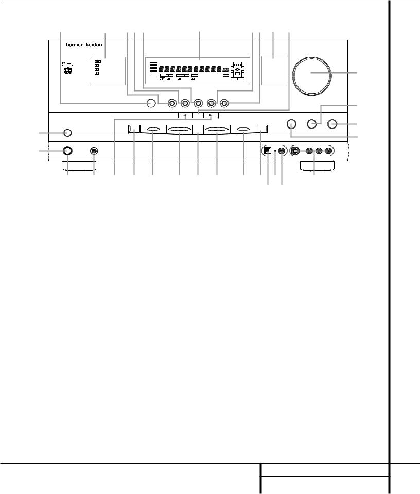
1 Main Power Switch
2 System Power Control
3 Power Indicator
4 Headphone Jack
5 Selector Buttons
6 Tone Mode
7 Surround Mode Selector
8 Tuning Selector
9 Tuner Band Selector
) Preset Stations Selector
1 Main Power Switch: Press this button to apply power to the AVR 310. When the switch is pressed in, the unit is placed in a Standby mode, as indicated by the amber LED 3 surrounding the System Power Control 2. This button MUST be pressed in to operate the unit. To turn the unit off and prevent the use of the remote control, this switch should be pressed until it pops out from the front panel so that the word “OFF” may be read at the top of the switch.
NOTE: This switch is normally left in the “ON” position.
2 System Power Control: When the Main Power Switch 1is “ON,” press this button to turn on the AVR 310; press it again to turn
! Input Source Selector
@ FM Mode Selector
# Digital Optical 3 Input
$ Digital Coax 3 Status Indicator
% Digital Coax 3 Jack
^ Video 4 Input Jacks
& Bass Control
* Balance Control
( Treble Control
Ó Volume Control
the unit off. Note that the Power Indicator surrounding the switch 3will turn green when the unit is on.
3 Power Indicator: This LED will be illuminated in amber when the unit is in the Standby mode to signal that the unit is ready to be turned on. When the unit is in operation, the indicator will turn green.
4Headphone Jack: This jack may be used to listen to the AVR 310’s output through a pair of headphones. Be certain that the headphones have a standard 1/4" stereo phone plug. Note that the main room speakers will automatically be turned off when the headphone jack is in use.
Ô Set Button
Input Indicators
Ò Delay
Ú Digital Input Selector
Û Main Information Display
Ù Channel Select Button
ıSpeaker Select Button
ˆ Test Tone Selector
˜ Surround Mode Indicators
¯ Remote Sensor Window
5 Selector Buttons: When you are establishing the AVR 310’s configuration settings, use these buttons to select from the choices available, as shown in the Main Information Display
Û.
6Tone Mode: Pressing this button enables or disables the Bass and Treble tone controls. When the button is pressed so that the words TONE IN appear in the Main Information Display Û, the settings of the Bass &and Treble (controls may be used to adjust the output signals. When the button is pressed so that the words TONE OUT appear in the Main Information Display Û, the output signal will be “flat,” without any bass or treble alteration, no matter how the actual Bass and Treble controls &(are adjusted.
5 FRONT PANEL CONTROLS

Front Panel Controls
7Surround Mode Selector: Press this button to change the surround mode by scrolling through the list of available modes. Note that depending on the type of input, some modes are not always available. (See page 26 for more information about surround modes.)
8Tuning Selector: Press the left side of the button to tune lower frequency stations and the right side of the button to tune higher frequency stations. When a station with a strong signal
is reached, the TUNED indicator Wwill be illuminated in the Main Information Display Û .
To tune manually, tap the button lightly and note that the tuner will step up one frequency increment per button press. When the button is held for a few seconds you will note that the unit will quickly search the frequency band. Release it once the fast tuning starts; the tuner will automatically scan for the next station with an acceptable signal and then stop.
9Tuner Band Selector: Pressing this button will automatically switch the AVR 310 to the Tuner mode. Pressing it again will switch between the AM and FM frequency bands. (See page 29 for more information on the tuner.)
) Preset Stations Selector: Press this button to scroll up or down through the list or stations that have been entered into the preset memory. (See page 30 for more information on tuner programming.)
!Input Source Selector: Press this button to change the input by scrolling up or down through the list of input sources.
@FM Mode Selector: Press this button to select Auto or Manual tuning. When the button is pressed so that the AUTO Indicator Xlights, the tuner will search for the next station with an acceptable signal when the Tuning Selector 8uéis pressed. When the button is pressed so that the AUTO Indicator Xis not lit, each press of the Tuning Selector 8ué will increase the frequency. (See page 29 for more information on using the tuner.)
#Digital Optical 3 Input: Connect the optical digital output of an audio or video product to this jack. When the Input is not in use, be certain to keep the plastic cap installed to avoid dust contamination that might degrade future performance.
$Digital Coax 3 Status Indicator: This LED indicator will normally light green to show that the Digital Coax 3 jack is operating as an input. When the jack has been configured as an output the indicator will turn red to show that the jack may be used for recording. (See page 19 for more information on configuring the Digital Coax 3 jack.)
%Digital Coax 3 Jack: This jack is normally used for connection to the output of portable audio devices, video game consoles or other products that have a coax digital jack. It may also be configured as an output jack, to feed a digital signal to a CD-R, MiniDisc or other digital recording device. (See page 30 for information on configuring the Digital Coax 3 Jack to an output.)
^Video 4 Input Jacks: These audio/video jacks may be used for temporary connection to video games or portable audio/video products such as camcorders and portable audio players.
& Bass Control: Turn this control to modify the low frequency output of the left/right channels by as much as ±10dB. Set this control to a suitable position for your taste or room acoustics.
* Balance Control: Turn this control to change the relative volume for the front left/right channels.
NOTE: For proper operation of the surround modes this control should be at the midpoint or “12 o’clock” position.
(Treble Control: Turn this control to modify the high frequency output of the left/right channels by as much as ±10dB. Set this control to a suitable position for your taste or room acoustics.
ÓVolume Control: Turn this knob clockwise to increase the volume, counterclockwise to decrease the volume. If the AVR 310 is muted, adjusting volume control will automatically release the unit from the silenced condition.
Ô Set Button: When making choices during the setup and configuration process, press this button to enter the desired setting as shown
in the Main Information Display Ûinto the AVR 310’s memory. The set button may also
be used to change the display brightness. (See page 32.)
Input Indicators: A green LED will light in front of the input that is currently being used as the source for the AVR 310.
Ò Delay: Press this button to begin the sequence of steps required to enter delay time settings. (See page 20 for more information on delay times.)
ÚDigital Input Selector: When playing a source that has a digital output, press this button to select between the Optical #i and Coaxial %j Digital inputs. (See pages 27–29 for more information on digital audio.)
Û Main Information Display: This display delivers messages and status indications to help you operate the receiver. (See pages 7–8 for a complete explanation of the Information Display.)
Ù Channel Select Button: Press this button to begin the process of trimming the channel output levels using an external audio source. (For more information on output level trim adjustment, see page 30.)
ı Speaker Select Button: Press this button to begin the process of selecting the speaker positions that are used in your listening room. (See page 21 for more information on setup and configuration.)
ˆTest Tone Selector: Press this button to begin the process of adjusting the channel output levels using the internal test tone as a reference. (For more information on output level adjustment, see page 22.)
˜ Surround Mode Indicators: A green LED will light in front of the surround mode that is currently in use.
¯Remote Sensor Window: The sensor behind this window receives infrared signals from the remote control. Aim the remote at this area and do not block or cover it unless an external remote sensor is installed.
6 FRONT PANEL CONTROLS
Front Panel Information Display
A
B
|
Z |
Y |
X W V |
UTSR |
|
Q |
|||
DTS |
MUTE |
|
AUTO TUNED |
ST |
MEMORY PRESET |
O |
|
O |
|
|
L 0 |
C |
0 R |
||||||
DOLBY D |
|
|
|
|
|
SLEEP |
|||
|
|
|
|
|
|
O |
|
O |
|
PCM |
|
|
|
|
|
|
O |
|
O |
MP3 |
|
|
|
|
|
|
|
||
|
|
|
|
|
|
LS |
LFE |
RS |
|
|
OPTICAL 1 2 3 |
COAXIAL 1 2 3 |
ANALOG VMAx NF |
5.1 LOGIC 7 CM |
OSD |
||||
|
O |
|
O |
||||||
|
DIGITAL |
PRO LOGIC |
3- STEREO 5 CH STEREO |
HALL 12 |
THEATER |
NIGHT |
|
MULTI |
|
C D E F G H I J KLM N O P
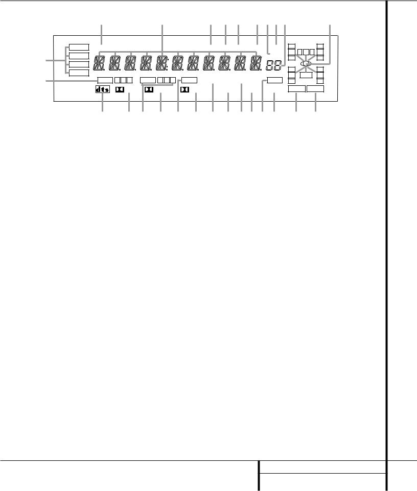
A Bitstream Indicators |
J 5 Channel Stereo Indicator |
S Preset Indicator |
B Optical Source Indicators |
K Logic 7 Mode Indicators |
T Sleep Indicator |
C DTS Mode Indicator |
L Hall Mode Indicator |
U Memory Indicator |
D Dolby Digital Indicator |
M OSD Indicator |
V Stereo Indicator |
E Coaxial Source Indicators |
N Theater Mode Indicator |
W Tuned Indicator |
F Dolby Pro Logic Indicator |
O Night Mode Indicator |
X Auto Indicator |
G Analog Input Indicator |
P Multiroom Indicator |
Y Main Information Display |
H Dolby 3 Stereo Indicator |
Q Speaker/Channel Input Indicators |
Z Mute Indicator |
I VMAx Mode Indicator |
R Preset Number/Sleep Timer |
|
ABitstream Indicators: When the input is a digital source, one of these indicators will light to display the specific type of data signal in use.
B Optical Source Indicators: These indicators light to show when an Optical Digital Input has been selected.
C DTS Mode Indicator: This indicator lights when a DTS-encoded source is playing.
D Dolby Digital Indicator: This indicator lights when a Dolby Digital source is being played.
ECoaxial Source Indicators: These indicators light to show when a Coaxial Digital Input has been selected.
F Dolby Pro Logic Indicator: This indicator lights when the Dolby ProLogic mode has been selected.
NOTE: It is possible to see the Dolby Pro Logic indicator lit simultaneously with the Dolby Digital indicator, even though the Dolby Digital surround mode has been selected. This is due to the specifications for Dolby Digital processing, which require that the Dolby Pro Logic mode apply any time a 2-channel Dolby signal is detected. If you desire 5.1-channel audio, check the audio settings in the menus for both your DVD player and your DVD disc to make sure that a 5.1-channel Dolby Digital soundtrack has been selected.
GAnalog Input Indicator: This indicator lights when an analog input source has been selected.
H Dolby 3 Stereo Indicator: This indicator lights when the Dolby 3 Stereo Mode has been selected.
IVMAx Mode Indicator: This indicator lights when the VMAx mode is in use. VMAx F appears when the Far Field VMAx mode is selected; VMAx N appears when the Near Field VMAx mode is selected. (See page 26 for a description of the VMAx Modes.)
J 5 Channel Stereo Indicator: This indicator lights when the 5 Channel Stereo mode has been selected.
K Logic 7 Mode Indicators: These indicators light when the Logic 7 mode is in use. LOGIC 7C appears for the Cinema version of Logic 7, LOGIC 7M appears for the Music version of Logic 7. (See page 26 for a description of the Logic 7 Modes.)
LHall Mode Indicators: These indicators light when one of the Hall modes has been selected.
MOSD Indicator: When the OSD system is in use, this indicator lights to remind you that the other indicators in this display do not function when the On Screen Display is being used.
NTheater Mode Indicator: This indicator lights to show that the Theater mode is in use.
O Night Mode Indicator: This indicator lights when the AVR 310 is in the Night mode, which preserves the dynamic range of digital program material at low volume levels.
PMultiroom Indicator: This indicator lights when the multiroom system is active. Note that it will remain lit when the multiroom system is in use even though the main room system is in the Standby mode and all other indicators are dark. (See page 34 for more information on the Multiroom system.)
Q Speaker/Channel Input Indicators: These indicators are multipurpose, indicating either the speaker type selected for each channel or the incoming data-signal configuration. The left, center, right, right surround and left surround speaker indicators are composed of three boxes, while the subwoofer is a single box. The center box lights when a “Small” speaker is selected, and the two outer boxes light when “Large” speakers are selected. When none of the boxes are lit for the center, surround or subwoofer channels, no speaker has been selected for one of those positions. (See page 21 for more information on configuring speakers.) The letters inside each of the center boxes display active input channels. For standard analog inputs, only the L and R will light, indicating a stereo input. When a digital source is playing, the indicators
7 FRONT PANEL INFORMATION DISPLAY

Front Panel Information Display
will light to display the channels being received at the digital input. When the letters flash, the digital input has been interrupted. (See page 28 for more information on the Channel Indicators.)
R Preset Number/Sleep Timer: When the tuner is in use, these numbers indicate the specific preset memory location in use. (See page 29 for more information on preset stations.) When the Sleep function is in use, these numbers show how many minutes remain before the unit goes into the Standby mode.
S Preset Indicator: This indicator lights when the tuner is in use to show that the Preset Number/Sleep Timer Ris showing the station’s preset memory number. (See page 30 for more information on tuner presets.)
TSleep Indicator: This indicator lights when the Sleep function is in use. The numbers in the Preset Number/Sleep Timer Indicators will show the minutes remaining before the AVR 310 goes into the Standby mode. (See page 25 for more information on the Sleep function.)
UMemory Indicator: This indicator flashes when entering presets and other information into the tuner’s memory.
V Stereo Indicator: This indicator lights when an FM station is being tuned in stereo.
W Tuned Indicator: This indicator lights when a station is being received with sufficient signal strength to provide acceptable listening quality.
XAuto Indicator: This indicator lights when the tuner’s Auto mode is in use.
Y Main Information Display: This display shows messages relating to the status, input source, surround mode, tuner, volume level or
other aspects of the AVR 310’s operation.
Z Mute Indicator: This indicator lights to remind you that the AVR 310’s output has been
silenced by pressing the Mute button ˚ 38 . Press the Mute button again to return to the previously selected output level.
8 FRONT PANEL INFORMATION DISPLAY
Rear Panel Connections
|
|
|
32 |
|
j |
g |
d |
|
|
|
|
|
|
|
|
|
|
|||
|
|
|
33 |
31 |
|
k i h f e c |
|
b a |
· |
° |
|
|
|
|
||||||
|
L |
R |
|
L |
|
R |
|
|
VIDEO |
S-VIDEO |
|
|
|
|
|
|
AC INPUT |
|
|
|
|
¡ |
|
|
|
|
VID 3 |
|
VID 3 |
|
|
|
|
|
|
|
~120V/60HZ A |
|
|
|
|
|
|
IN |
|
|
1 |
|
|
|
|
|
|
|
|
|
|
|
||||
|
|
|
TAPE |
|
|
|
|
|
|
|
|
|
|
|
|
|
|
|
|
|
™ |
|
|
OUT |
|
|
|
OPT |
|
|
|
MULTI |
|
|
|
|
|
|
|
|
|
|
|
|
|
IN |
|
|
IN |
|
|
|
|
|
|
|
|
|
|
|||
|
|
|
|
|
|
|
|
|
|
|
|
|
|
|
|
|
||||
|
|
|
|
|
|
|
|
|
|
|
|
|
|
|
|
|
|
|||
|
|
|
|
|
|
VID 2 |
2 |
VID 2 |
|
IN |
|
|
|
|
|
|
|
|
|
|
|
£ |
|
|
|
|
|
|
|
|
|
|
|
|
|
|
|
|
|||
|
|
|
|
|
OUT |
|
|
OUT |
|
|
|
|
|
|
|
|
|
|
MODEL NO. AVR 310 |
|
|
ANTENNA |
|
|
|
|
|
|
IN |
|
|
|
|
|
C |
|
US |
|
|||
|
|
|
|
|
|
|
|
|
|
|
|
|
|
|
|
|||||
|
|
|
|
|
|
|
1 |
|
|
|
|
|
|
|
|
|
R |
NORTHRIDGE |
||
|
|
|
|
|
|
|
|
|
|
|
OUT |
|
|
|
|
|
|
LISTED |
|
|
|
|
|
|
|
|
|
COAX |
|
|
|
|
|
|
|
|
|
|
CALIFORNIA, USA |
||
|
|
|
|
|
|
|
|
|
|
|
|
|
|
|
|
|
E191351 |
|
||
|
|
AM |
|
|
|
IN |
|
|
IN |
|
REMOTE |
|
|
|
|
|
|
40KK |
|
|
|
|
|
|
|
|
|
|
|
|
|
|
|
|
AUDIO EQUIPMENT |
MADE IN CHINA |
|||||
|
|
|
|
|
|
|
2 |
|
|
|
|
|
|
|
|
|||||
¢ |
|
|
|
|
|
VID 1 |
VID 1 |
|
|
|
|
|
|
|
|
|
|
|
||
|
|
|
|
|
|
|
|
|
|
|
|
|
|
|
|
|
||||
|
|
|
|
|
|
DIGITAL IN |
|
|
|
|
|
|
|
|
|
|
|
|
|
|
|
|
GND |
|
|
|
OUT |
|
OUT |
|
|
|
|
|
|
|
|
|
|
|
|
|
|
|
|
|
|
|
|
|
|
|
|
|
|
|
|
|
AC OUTLETS |
|||
|
∞ |
|
|
|
|
|
|
|
|
|
|
|
|
|
|
|
|
|
|
|
|
|
|
|
|
|
|
|
|
|
|
|
|
|
|
|
|
|
|
~120V/60Hz |
|
§ |
|
|
|
|
|
OPT |
|
|
|
|
|
|
|
|
|
|
|
|
UNSWITCHED / 100W MAX |
|
|
|
|
|
|
|
|
|
|
|
|
|
|
|
|
|
|
|
|||
¶ |
FM |
|
|
|
DVD |
|
DVD |
|
|
|
|
|
|
|
|
|
|
|||
|
|
|
|
|
|
|
|
|
|
|
|
|
|
|
|
|||||
|
75Ω |
|
|
|
|
|
|
|
|
|
|
|
|
|
|
|
|
|
|
|
|
|
|
|
|
|
|
COAX |
|
|
|
|
|
|
|
|
|
+ |
|
|
|
• |
|
|
|
|
|
CD |
|
MON. |
|
|
|
|
+ |
|
|
|
|
|
||
|
|
|
|
|
|
|
|
|
|
|
|
|
|
|
|
|||||
|
|
|
|
|
|
OUT |
|
|
|
|
|
|
|
|
|
|
||||
|
|
|
|
|
|
|
DIGITAL OUT |
|
|
|
|
|
|
|
|
|
|
|
||
|
CENTER |
SL |
FL |
ML |
|
|
|
|
|
|
|
|
|
|
|
|
|
|
SWITCHED / 100W MAX |
|
|
|
|
|
|
|
|
|
|
|
|
|
|
|
|
|
|
||||
|
ª |
|
|
|
|
|
|
|
|
|
|
|
|
– |
|
|
– |
|
|
|
|
|
|
|
|
|
|
|
|
|
|
|
|
|
|
|
|
|
|
|
|
|
|
|
|
|
|
|
|
|
|
|
|
|
|
|
|
RIGHT |
LEFT |
|
|
SERIAL NO. |
|
SUBWOOFER |
SR |
FR |
MR |
FL |
FR |
SL |
SR |
CENTER |
SUBWOOFER |
RIGHT |
LEFT |
CENTER |
|
|
|
|
|
||
|
|
|
|
|
|
|
|
|||||||||||||
|
6 CH. DIRECT INPUT |
|
MULTI OUT |
|
|
PRE |
OUT |
|
|
FRONT SPKRS (8Ω ) |
SPKR (8Ω |
) |
|
SURR. SPKRS (8Ω ) |
|
|
|
|||
|
|
|
|
‚ |
|
|
⁄ |
|
|
¤ ‹ |
|
|
|
› |
|
fi |
|
|
fl |
‡ |
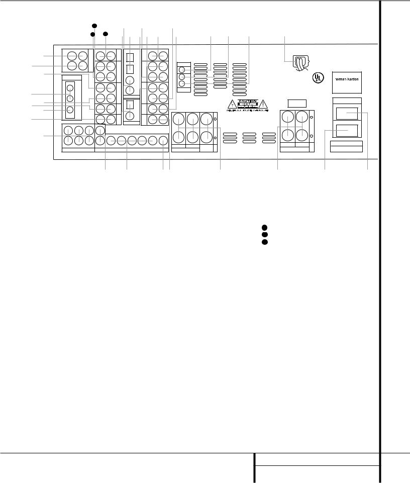
¡ Tape Inputs |
|
|
|
|
|
|
|
fi Surround Speaker Outputs |
|
|
j Coaxial Digital Inputs |
|
|
|||||||
™ Tape Outputs |
|
|
|
|
|
|
|
fl Switched AC Accessory Outlet |
|
k Digital Audio Outputs |
|
|
||||||||
£ Video 1 Audio Inputs |
|
|
|
|
|
|
‡ Unswitched AC Accessory Outlet |
|
31 Video 3 Audio Inputs |
|
|
|||||||||
¢ AM Antenna |
|
|
|
|
|
|
|
° AC Power Cord |
|
|
|
|
32 Video 2 Audio Inputs |
|
|
|||||
∞ Video 1 Audio Outputs |
|
|
|
|
|
|
· Remote IR Output |
|
|
|
33 Video 2 Audio Outputs |
|
|
|||||||
§ DVD Audio Inputs |
|
|
|
|
|
|
|
a Remote IR Input |
|
|
|
|
|
|
|
|
|
|||
¶ FM Antenna |
|
|
|
|
|
|
|
b Multiroom IR Input |
|
|
|
|
|
|
|
|
||||
• CD Inputs |
|
|
|
|
|
|
|
c DVD Video Inputs |
|
|
|
|
|
|
|
|
|
|||
ª 6-Channel Direct Inputs |
|
|
|
|
|
|
d Video 1 Video Outputs |
|
|
|
|
|
|
|
|
|||||
‚ Multiroom Outputs |
|
|
|
|
|
|
|
e Video 3 Video Inputs |
|
|
|
|
|
|
|
|
||||
⁄ Preamp Outputs |
|
|
|
|
|
|
|
f Video 2 Video Inputs |
|
|
|
|
|
|
|
|
||||
¤ Subwoofer Output |
|
|
|
|
|
|
|
g Video 2 Video Outputs |
|
|
|
|
|
|
|
|
||||
‹ Video Monitor Outputs |
|
|
|
|
|
|
h Video 1 Video Inputs |
|
|
|
|
|
|
|
|
|||||
› Front Speaker Outputs |
|
|
|
|
|
|
i Optical Digital Inputs |
|
|
|
|
|
|
|
|
|||||
|
|
|
|
|
|
|
|
|
|
|
|
|
|
|
|
9 REAR PANEL CONNECTIONS |
||||

Rear Panel Connections
¡Tape Inputs: Connect these jacks to the PLAY/OUT jacks of an audio recorder.
™Tape Outputs: Connect these jacks to the RECORD/INPUT jacks of an audio recorder.
£Video 1 Audio Inputs: Connect these jacks to the PLAY/OUT audio jacks on a VCR or other video source.
¢AM Antenna: Connect the AM loop antenna supplied with the receiver to these terminals. If an external AM antenna is used, make connections to the AM and GND terminals in accordance with the instructions supplied with the antenna.
∞ Video 1 Audio Outputs: Connect these jacks to the RECORD/INPUT audio jacks on a VCR.
§ DVD Audio Inputs: Connect these jacks to the analog audio jacks on a DVD or other video source.
¶ FM Antenna: Connect the supplied indoor or an optional external FM antenna to this terminal.
• CD Inputs: Connect these jacks to the output of a compact disc player or CD changer.
ª 6-Channel Direct Inputs: If an external digital audio decoder is used, connect the outputs of that decoder to these jacks.
‚ Multiroom Outputs: Connect these jacks to an optional audio power amplifier to listen to the source selected by the mulitroom system in a remote room.
⁄ Preamp Outputs: These jacks may be connected to an external power amplifier.
¤ Subwoofer Output: Connect this jack to the line-level input of a powered subwoofer. If an external subwoofer amplifier is used, connect this jack to the subwoofer amplifier input.
‹Video Monitor Outputs: Connect this jack to the composite or S-Video input of a TV monitor or video projector to view the on-screen menus and the output of any standard video source selected by the receiver’s video switcher.
› Front Speaker Outputs: Connect these outputs to the matching + or – terminals on your front speakers. When making speaker connections, always make certain to maintain
correct polarity by connecting the red (+) terminals on the AVR 310 to the red (+) terminals on the speaker and the black (–) terminals on the AVR 310 to the black (–) terminals on the speakers. (See page 15 for more information on speaker polarity.)
fi Surround Speaker Outputs: Connect these outputs to the matching + or – terminals on your left and right surround speakers. When making speaker connections always make certain to maintain correct polarity by connecting the red (+) terminals on the AVR 310 to the red
(+) terminals on the speakers and the black (–) terminals on the AVR 310 to the black (–) terminals on the speakers. See page 15 for more information on speaker polarity.
fl Switched AC Accessory Outlet: This outlet may be used to power any device you wish to have turned on when the AVR 310 is turned on with the System Power Control switch 2.
‡ Unswitched AC Accessory Outlet: This outlet may be used to power any AC device. The power will remain on at this outlet regardless of whether the AVR 310 is on or off.
Note: The total power consumption of all devices connected to the accessory outlets should not exceed 100 watts.
°AC Power Cord: Connect the AC plug to an unswitched AC wall output.
· Remote IR Output: This connection permits the IR sensor in the receiver to serve other remote controlled devices. Connect this jack to the “IR IN” jack on Harman Kardon (or other compatible) equipment.
a Remote IR Input: If the AVR 310’s frontpanel IR sensor is blocked due to cabinet doors or other obstructions, an external IR sensor may be used. Connect the output of the sensor to this jack.
b Multiroom IR Input: Connect the output of an IR sensor in a remote room to this jack to operate the AVR 310’s multiroom control system.
c DVD Video Inputs: Connect these jacks to the composite or S-Video output jacks on a DVD or other video source.
d Video 1 Video Outputs: Connect these jacks to the RECORD/INPUT composite or S-Video jack on a VCR.
e Video 3 Video Inputs: Connect these jacks to the PLAY/OUT composite or S-Video jacks on a VCR or other video source.
fVideo 2 Video Inputs: Connect these jacks to the PLAY/OUT composite or S-Video jacks on a VCR or other video source.
gVideo 2 Video Outputs: Connect these jacks to the RECORD/INPUT composite or S-Video jacks on a VCR.
hVideo 1 Video Inputs: Connect these jacks to the PLAY/OUT composite or S-Video jacks on a VCR or other video source.
i Optical Digital Inputs: Connect the optical digital output from a DVD player, HDTV receiver, LD player or CD player to these jacks. The signal may be either a Dolby Digital signal, a DTS signal or a standard PCM digital source.
j Coaxial Digital Inputs: Connect the coax digital output from a DVD player, HDTV receiver, LD player or CD player to these jacks. The signal may be either a Dolby Digital signal, DTS signal or a standard PCM digital source. Do not connect the RF digital output of an LD player to these jacks.
k Digital Audio Outputs: Connect these jacks to the matching digital input connector on a digital recorder such as a CD-R or MiniDisc recorder.
31Video 3 Audio Inputs: Connect these jacks to the PLAY/OUT audio jacks on a VCR or other video source.
32Video 2 Audio Inputs: Connect these jacks to the PLAY/OUT audio jacks on a VCR or other video source.
33Video 2 Audio Outputs: Connect these jacks to the RECORD/INPUT audio jacks on a VCR or other video source.
10 REAR PANEL CONNECTIONS

Main Remote Control Functions
a Power On Button
b IR Transmitter Window
c Program/SPL Indicator
d Power Off Button
e Input Selectors
f AVR Selector
g AM/FM Tuner Select
h Learn Button
i Test Button
j Sleep Button
k Surround Mode Selector
l Night Mode
m Channel Select Button
n ⁄/ ¤ Buttons
o ‹ Button
pSet Button
q Digital Select
r Numeric Keys
s Tuner Mode
t Direct Button
u Tuning Up/Down
v OSD Button
w Macro Buttons
x Transport Controls
y Skip Up/Down Buttons
z Disc Skip Buttons
` Preset Up/Down
●28 Clear Button
●29 Memory Button
●30 Delay/Prev. Ch.
●31 › Button
●32 Speaker Select
●33 Multiroom
●34 Volume Up/Down
●35 TV/Video Selector
●36 SPL Indicator Select
●37 6-Channel Direct Input
●38 Mute
●39 EzSet Sensor Microphone
c b a
dOFF
e
fAVR V C R VID1
g
h LEARN
i  j
j
SLEEP
CH.
SURR.
k
l
|
|
|
E |
|
|
|
ID |
|
|
m |
G |
U |
|
. |
|
|
|||
|
|
|
H |
|
n |
|
|
|
C |
|
|
|
|
|
o p |
|
|
|
|
q |
|
|
D |
|
|
|
|
|
I |
|
|
|
|
G |
|
|
|
|
I |
|
|
|
|
T |
|
E |
|
A |
|
|
X |
|
L |
|
|
|
I |
|
|
n |
|
T |
|
|
|
|
|
|
|
r |
|
|
|
1 |
|
|
|
|
|
|
|
|
|
5 |
s |
|
|
TUN-M |
|
|
|
|
||
t
POWER 
|
TM |
ON |
|
|
|
MUTE |
||
|
|
|
|
|
|
|||
DVD |
CD |
|
|
|
TAPE |
|||
T V |
CBL/SAT |
|
|
|
|
|
|
|
VID2 |
VID3 |
|
|
|
VID4 |
|||
AM/FM |
6 CH. |
|
|
|
|
SPL |
||
TEST |
T/V |
|
|
|
|
|
|
|
NIGHT |
M-ROOM |
|
|
|
VOL. |
|||
|
|
|
|
M |
|
|
||
|
|
|
|
|
|
E |
|
|
|
|
|
|
|
|
N |
|
|
|
|
S |
|
|
|
U |
||
|
|
|
P |
|
|
|
|
|
|
|
|
K |
|
|
|
|
|
|
|
|
R |
|
|
|||
SET |
|
|
|
|
|
|
|
|
|
|
|
|
|
|
Y |
|
|
|
|
|
|
|
A |
|
|
|
|
|
|
|
L |
|
|
|
|
|
|
|
E |
|
|
|
. |
|
|
|
|
D |
|
|
|
|
|
|
|
|
|
|
|
|
.C |
H |
|
|
|
|
|
|
|
V |
|
|
|
|
|
|
|
E |
|
|
|
|
|
|
|
R |
|
|
|
|
|
|
|
P |
|
|
||
2 |
3 |
|
|
|
|
4 |
|
|
6 |
7 |
|
|
|
8 |
|
|
|
9 |
0 |
|
MEM |
|
||||
u |
|
DIRECT |
CLEAR |
|
TUNING |
|
|
PRESET |
|
|
|
|
||
|
|
OSD |
D.SKIP |
|
v |
|
|
|
|
w |
M1 |
M2 |
M3 |
M4 |
|
NOTE: The function names shown here are each |
|
|
button’s feature when used with the AVR 310. |
x |
|
Most buttons have additional functions when |
|
|
|
|
|
used with other devices. See pages 40–41 for a |
y |
|
list of these functions. |
|
|
|
DWN |
UP |
|
|
SKIP |

 310
310
39
38
37
36
35
34
33
32
31
30
29
28
`
z
11 MAIN REMOTE CONTROL FUNCTIONS
Main Remote Control Functions
IMPORTANT NOTE: The AVR 310’s remote may be programmed to control up to eight devices, including the AVR 310. Before using the remote, it is important to remember to press the Input Selector button ethat corresponds to the unit you wish to operate. In addition, the AVR 310’s remote is shipped from the factory to operate the AVR 310 and most Harman Kardon CD or DVD players and cassette decks. The remote is also capable of operating a wide variety of other products using the control codes that are part of the remote. Before using the remote with other products, follow the instructions on pages 35–39 to program the proper codes for the products in your system.
It is also important to remember that many of the buttons on the remote take on different functions, depending on the product selected using the Device Control Selectors. The descriptions shown here primarily detail the functions of the remote when it is used to operate the AVR 310. (See page 37 for information about alternate functions for the remote’s buttons.)
aPower On Button: Press this button to turn on the power to a device selected by pressing one of the Input Selectors e.
b IR Transmitter Window: Point this window towards the AVR 310 when pressing buttons on the remote to make certain that infrared commands are properly received.
cProgram/SPL Indicator: This three-color indicator is used to guide you through the process of programming the remote or learning commands from a remote into the AVR 310’s remote code memory and it is also used as a level indicator when using the remote’s EzSet capabilities. (See page 22 for more information on setting output levels, and see page 35 for information on programming the remote.)
d Power Off Button: Press this button to place the AVR 310 or a selected device in the Standby mode. Note that this will turn off the main room functions, but if the Multiroom system is activated, it will continue to function.
e Input Selectors: Pressing one of these buttons will perform three actions at the same time. First, if the AVR 310 is not turned on, this will power up the unit. Next, it will select the source shown on the button as the input to the AVR 310. Finally, it will change the remote control so that it controls the device selected. After pressing one of these buttons you must press the AVR Selector button f again to operate the AVR 310’s functions with the remote.
fAVR Selector: Pressing this button will switch the remote so that it will operate the AVR 310’s functions. If the AVR 310 is in the Standby mode, it will also turn the AVR 310 on.
gAM/FM Tuner Select: Press this button to select the AVR 310’s tuner as the listening choice. Pressing this button when the tuner is already in use will select between the AM and FM bands.
h Learn Button: Press this button to begin the process of “learning” the codes from another product’s remote into the AVR 310’s remote.
(See page 36 for more information on using the remote’s learning function.)
iTest Button: Press this button to begin the sequence used to calibrate the AVR 310’s output levels. (See page 22 for more information on calibrating the AVR 310.)
j Sleep Button: Press this button to place the unit in the Sleep mode. After the time shown in the display, the AVR 310 will automatically go into the Standby mode. Each press of the button changes the time until turn-off in the following order:
|
|
90 |
|
80 |
|
|
70 |
|
|
60 |
|
50 |
|
|
|
|
min |
|
min |
|
min |
|
min |
|
|
min |
|
||
|
|
|
|
|
|
|
|
|
|
|
|
|
|
|
|
40 |
|
30 |
|
|
20 |
|
|
10 |
|
|
OFF |
||
|
|
|
|
|
|
|
|
|||||||
|
|
min |
|
min |
|
min |
|
min |
|
|
||||
|
|
|
|
|
|
|
|
|
||||||
Note that this button is also used to change channels on your TV when the TV is selected.
When the AVR 310 remote is being programmed with the codes to operate another device, this button is also used in the “Auto Search” process. (See page 35 for more information on programming the remote.)
k Surround Mode Selector: Press this button to begin the process of changing the surround mode. After the button has been pressed, use the ⁄/¤ buttons n to select the desired surround mode. (See page 27 for more information.) Note that this button is also used to tune channels when the TV is selected using the device Input Selector e. When the AVR 310 remote is being programmed with the codes of another device, this button is also used in the “Auto Search” process. (See page 35 for more information on programming the remote.)
l Night Mode: Press this button to activate the Night mode. This mode is available in specially encoded digital sources, and it preserves
dialog (center channel) intelligibility at low volume levels.
m Channel Select Button: This button is used to start the process of setting the AVR 310’s output levels to an external source. Once this button is pressed, use the ⁄/¤ buttons nto select the channel being adjusted, then press the Set button p, followed by the ⁄/¤ buttons again, to change the level setting. (See page 30 for more information.)
n ⁄/¤ Buttons: These are multi-purpose buttons. They will be used most frequently to select a surround mode. To change the surround mode, first press the Surround Mode ¤ selector k. Next press these buttons to scroll up or down through the list of surround modes that appear in the Main Information Display 25.. These buttons are also used to increase or decrease output levels when configuring the unit with either the internal test tone or an external source. They are also used to enter delay time settings after the Delay button 30 has been pressed.
o ‹ Button: This button is used to change the menu selection or setting during some of the setup procedures for the AVR 310.
pSet Button: This button is used to enter settings into the AVR 310’s memory. It is also used in the setup procedures for delay time, speaker configuration and channel output level adjustment.
q Digital Select: Press this button to assign one of the digital inputs # %to a source. (See page 27 for more information on using digital inputs.)
r Numeric Keys: These buttons serve as a ten-button numeric keypad to enter tuner preset positions. They are also used to select channel numbers when TV has been selected on the remote, or to select track numbers on a CD, DVD or LD player, depending on how the remote has been programmed.
sTuner Mode: Press this button when the tuner is in use to select between automatic tuning and manual tuning. When the button is pressed so that the AUTO indicator Xgoes out, pressing the Tuning buttons u8≠ will move the frequency up or down in singlestep increments. When the FM band is in use, pressing this button when a station’s signal is weak will change to monaural reception. (See page 29 for more information.)
12 MAIN REMOTE CONTROL FUNCTIONS
Main Remote Control Functions
t Direct Button: Press this button when the tuner is in use to start the sequence for direct entry of a station’s frequency. After pressing the button simply press the proper Numeric Keys rto select a station. (See page 29 for more information on the tuner.)
uTuning Up/Down: When the tuner is in use, these buttons will tune up or down through the selected frequency band. If the Tuner Mode button s@has been pressed so that the AUTO indicator Xis illuminated, pressing and holding either of the buttons for three seconds will cause the tuner to seek the next station with acceptable signal strength for quality reception. When the AUTO indicator Xis NOT illuminated, pressing these buttons will tune stations in single-step increments. (See page 29 for more information.)
v OSD Button: Press this button to activate the On Screen Display (OSD) system used to set up or adjust the AVR 310’s parameters.
w Macro Buttons: Press these buttons to store or recall a “Macro”, which is a pre-programmed sequence of commands stored in the remote. (See page 36 for more information on storing and recalling macros.)
xTransport Controls: These buttons do not have any functions for the AVR 310, but they may be programmed for the forward/ reverse play operation of a wide variety of CD or DVD players, and audio or video cassette recorders. (See page 38 for more information on programming the remote.)
y Skip Up/Down Buttons: These buttons do not have a direct function with the AVR 310, but when used with a compatibly programmed CD or DVD changer they will change the disc currently being played in the changer.
z Disc Skip Buttons: These buttons have no direct function for the AVR 310, but they are often used when the remote is programmed to operate a CD or DVD changer to change the discs in the changer. (See page 37 for more information on using the remote with other devices.)
` Preset Up/Down: When the tuner is
in use, press these buttons to scroll through the stations programmed into the AVR 310’s mem-
ory. When some source devices, such as CD players, VCRs and cassette decks, are selected using the device Input Selectors e, these buttons may function as chapter step or track advance.
28Clear Button: Press this button to clear incorrect entries when using the remote to directly enter a radio station’s frequency.
29Memory Button: Press this button to enter a radio station into the AVR 310’s preset memory. Once the MEMORY indicator U flashes, you have five seconds to enter a preset memory location using the Numeric Keys r. (See page 30 for more information.)
30Delay/Prev Ch.: Press this button to begin the process for setting the delay times used by the AVR 310 when processing surround sound. After pressing this button, the delay times are entered by pressing the Set button pand then using the ⁄/¤ buttons nto change the setting. Press the Set button again to complete the process. (See page 20 for more information.)
31› Button: Press this button to change a setting or selection when configuring many of the AVR 310’s settings.
32Speaker Select: Press this button
to begin the process of configuring the
AVR 310’s Bass Management System for use with the type of speakers used in your system. Once the button has been pressed, use the ⁄/¤ buttons n to select the channel you wish to set up. Press the Set button p and then select another channel to configure. When all adjustments have been completed, press the Set button ptwice to exit the settings and return to normal operation. (See page 21 for more information.)
33Multi-Room: Press this button to activate the multiroom system or to begin the process of changing the input or volume level for the second zone. (See page 34 for more information on the multiroom system.)
34Volume Up/Down: Press these buttons to raise or lower the system volume.
35TV/Video Button: This button does not have a direct function on the AVR 310, but when used with a compatibly programmed VCR, DVD or satellite receiver that has a “TV/Video” function, pressing this button will switch between the output of the player or receiver and the external video input to that player. Consult the Owner’s Manual for your specific player or receiver for the details of how it implements this function.
36SPL Indicator Select: This button activates the AVR 310’s EzSet function to quickly and accurately calibrate the AVR 310’s output levels. Press and hold the button for three seconds and then release it. Note that the Test Tone will begin circulating, and the Program Indicator cwill change colors. During this sequence, EzSet will automatically adjust the output levels for all channels until they are equal, as shown by the Program Indicator lighting green for each channel. Press this button again when the adjustment is complete to turn off the test tone. (See page 23 for more information on EzSet.)
376-Ch. Direct Input: Press this button
to select the component connected to the
6-Channel Direct Input ª as the source.
38 Mute: Press this button to momentarily silence the AVR 310 or TV set being controlled, depending on which device has been selected.
When the AVR 310 remote is being programmed to operate another device, this button is pressed with the Input Selector button e to begin the programming process. (See page 35 for more information on programming the remote.)
39 EzSet Sensor Microphone: The sensor microphone for the EzSet microphone is behind these slots. When using the remote to calibrate speaker output levels using EzSet, be sure that you do not hold the remote in a way that covers these slots. (See page 23 for more information on using EzSet.)
13 MAIN REMOTE CONTROL FUNCTIONS
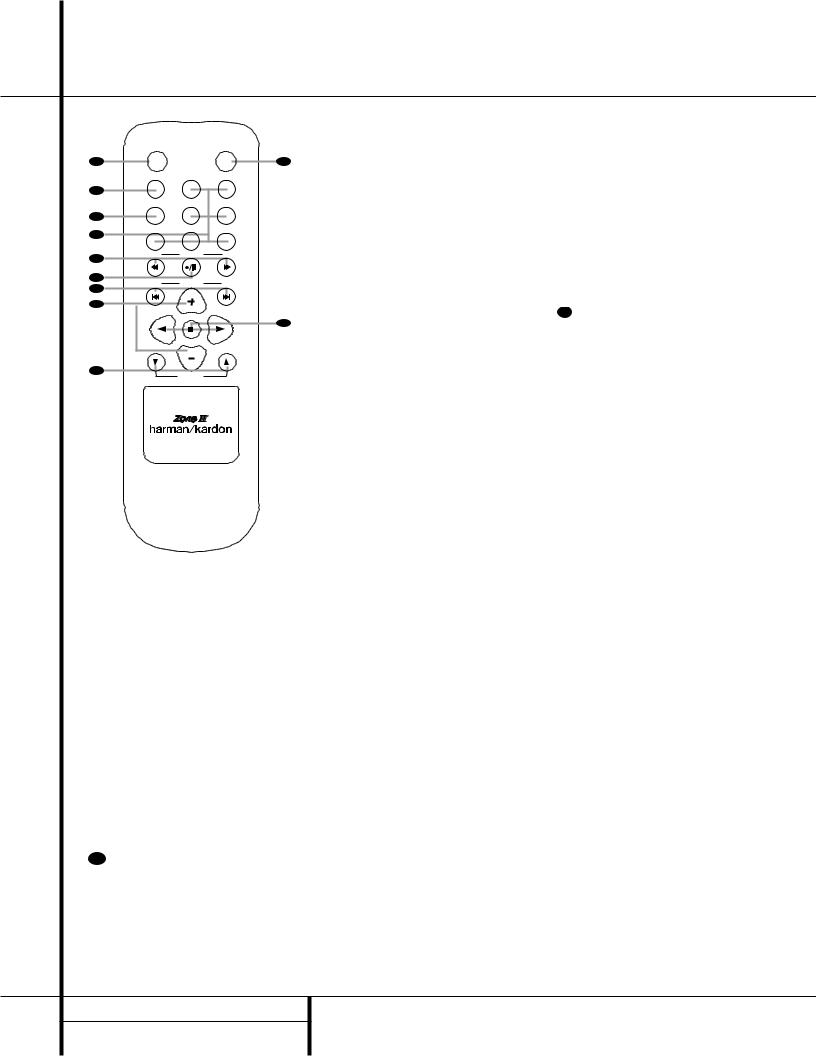
Zone II Remote Control Functions
|
POWER |
|
MUTE |
|
A |
OFF |
|
|
|
|
AVR |
VID1 |
VID2 |
|
B |
|
|
|
|
|
AM/FM |
VID3 |
VID4 |
|
C |
|
|
|
|
D |
DVD |
CD |
TAPE |
|
|
|
|
||
E |
DN |
TUNING |
UP |
|
|
|
|
||
F |
DN |
PRESET |
UP |
|
G |
||||
|
|
|
||
H |
|
|
|
|
|
|
DISC SKIP |
|
|
|
|
DISC SKIP |
|
|
I |
|
VOLUME |
|
|
|
|
|
å Power Off
∫ AVR Selector
ç AM/FM Tuner Select
∂ Input Selectors
≠ Tuning Up/Down – Fast Play
ƒ Record/Pause
© Preset/Track Skip
˙ Disc Skip
I Volume Up/Down
∆ Play Forward/Reverse/Stop
˚ Mute
åPower Off: When used in the room where the AVR 310 is located, press this button
Kto place the unit in Standby. When it is used in a remote room with a sensor that is connected to the Multi IR jack b, this button turns the Multi-Room system on and off.
∫AVR Selector: Press this button to turn on the AVR 310. The input in use when the unit was last on will be selected.
çAM/FM Tuner Select: Press this button to select the Tuner as the input to the Multiroom system. Press it again to change
Jbetween the AM and FM bands.
∂Input Selectors: When the AVR 310 is off, press one of these buttons to select a specific input and turn the unit on. When the unit is already in use, pressing one of these buttons will change the input.
≠Tuning Up/Down – Fast Play: When this remote is used in the same room as the AVR 310, these buttons may be used to change the frequency of the tuner. These buttons may also control the Fast Play or Fast Reverse functions of compatible Harman Kardon CD, DVD or cassette decks in the same room, or from a remote room when an IR link is connected to the AVR 310.
ƒRecord/Pause: Press this button to activate the Record or Pause function on compatible Harman Kardon CD, DVD or Cassette Deck products.
NOTE: The Zone II remote may be used in either the same room where the AVR 310 is located, or it may be used in a separate room with an optional infrared sensor that is connected to the AVR 310’s Multi IR input jack b. When it is used in the same room as the AVR 310, it will control the functions of the AVR 310 or any compatible Harman Kardon products in that room. When it is used in a separate room via a sensor connected to the Multi IR Jack b, the buttons for power, input source,
©Preset Up/Down – Track Skip: When the AVR 310’s tuner is selected as the input source, these buttons will move up or down through the list of stations that have been stored in the preset memory. When a CD or DVD player is selected, these buttons activate the forward or reverse track or chapter skip functions.
˙Disc Skip: Press this button to change discs on compatible Harman Kardon CD or DVD players.
I Volume Up/Down: When used in the room where the AVR 310 is located, press this button to raise or lower the volume in that room. When it is used in a remote room with a sensor that is connected to the Multi IR Jack b, this button will raise or lower the volume in the remote room.
∆Play Forward/Reverse/Stop: Press these buttons to control compatible
Harman Kardon CD, DVD or cassette players.
˚Mute: When used in the room where the AVR 310 is located, press this button to temporarily silence the unit. When it is used in a remote room with a sensor that is connected to the Multi IR Jack b, this button will temporarily silence the feed to the remote room only. Press the button again to return to the previous volume level.
volume and mute will control the source and volume for the second zone, as connected to the Multi Out Jacks ‚. (See page 34 for complete information on using the Multiroom system.)
14 ZONE II REMOTE CONTROL FUNCTIONS
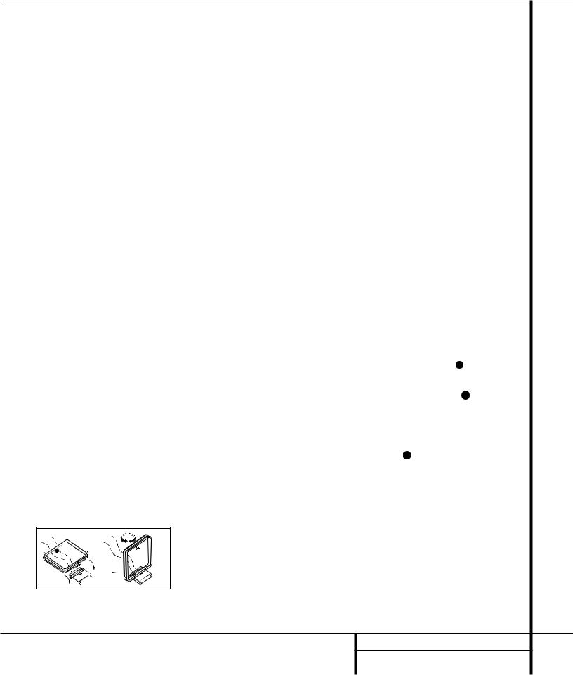
Installation and Connections
System Installation
After unpacking the unit, and placing it on a solid surface capable of supporting its weight, you will need to make the connections to your audio and video equipment.
Audio Equipment Connections
We recommend that you use high-quality interconnect cables when making connections to source equipment and recorders to preserve the integrity of the signals.
When making connections to audio source equipment or speakers it is always a good practice to unplug the unit from the AC wall outlet. This prevents any possibility of accidentally sending audio or transient signals to the speakers that may damage them.
1. Connect the analog output of a CD player to the CD inputs •.
NOTE: When the CD player has both fixed and variable audio outputs it is best to use the fixed output unless you find that the input to the receiver is so low that the sound is noisy, or so high that the signal is distorted.
2.Connect the analog Play/Out jacks of a cassette deck, MD, CD-R or other audio recorder to the Tape Input jacks ¡. Connect the analog Record/In jacks on the recorder to the Tape Output jacks ™ on the AVR 310.
3.Connect the output of any digital sources to the appropriate input connections on the AVR 310 rear panel. Note that the Optical and Coaxial digital inputs ij#%may be used with a Dolby Digital or DTS source or the output of a conventional CD or LD player’s PCM (S/P-DIF) output.
4.Connect the Coaxial or Optical Digital Outputs k on the rear panel of the AVR to the matching digital input connections on a CD-R or MiniDisc recorder.
5.Assemble the AM Loop Antenna supplied with the unit as shown below. Connect it to the AM and GND screw terminals ¢.
6.Connect the supplied FM antenna to the FM (75 ohm) connection ¶. The FM antenna may be an external roof antenna, an inside powered or wire lead antenna or a connection from a cable TV system. Note that if the antenna or connection uses 300-ohm twin-lead cable, you must use the 300-ohm-to-75-ohm adapter supplied with the unit to make the connection.
7.Connect the front, center and surround speaker outputs ›fi to the respective speakers.
To assure that all the audio signals are carried to your speakers without loss of clarity or resolution, we suggest that you use high-quality speaker cable. Many brands of cable are available and the choice of cable may be influenced by the distance between your speakers and the receiver, the type of speakers you use, personal preferences and other factors. Your dealer or installer is a valuable resource to consult in selecting the proper cable.
Regardless of the brand of cable selected, we recommend that you use a cable constructed of fine, multistrand copper with a gauge of 14 or smaller. Remember that in specifying cable, the lower the number, the thicker the cable.
Cable with a gauge of 16 may be used for short runs of less than ten feet. We do not recommend that you use cables with an AWG equivalent of 18 or higher due to the power loss and degradation in performance that will occur.
Cables that are run inside walls should have the appropriate markings to indicate listing with UL, CSA or other appropriate testing agency standards. Questions about running cables inside walls should be referred to your installer or a licensed electrical contractor who is familiar with the NEC and/or the applicable local building codes in your area.
When connecting wires to the speakers, be certain to observe proper polarity. Remember to connect the “negative” or “black” wire to the same terminal on both the receiver and the speaker. Similarly, the “positive” or “red” wire should be connected to like terminals on the AVR 310 and speaker.
NOTE: While most speaker manufacturers adhere to an industry convention of using black terminals for negative and red ones for positive, some manufacturers may vary from this configuration. To assure proper phase and optimal
performance, consult the identification plate on your speaker or the speaker’s manual to verify polarity. If you do not know the polarity of your speaker, ask your dealer for advice before proceeding, or consult the speaker’s manufacturer.
We also recommend that the length of cable used to connect speaker pairs be identical. For example, use the same length piece of cable to connect the front-left and front-right or surround-left and surround-right speakers, even if the speakers are a different distance from the AVR 310.
8. Connections to a subwoofer are normally made via a line level audio connection from the Subwoofer Output ¤ to the line-level input of a subwoofer with a built-in amplifier. When a passive subwoofer is used, the connection first goes to a power amplifier, which will be connected to one or more subwoofer speakers. If you are using a powered subwoofer that does not have line-level input connections, follow the instructions furnished with the speaker for connection information.
Video Equipment Connections
Video equipment is connected in the same manner as audio components. Again, the use of highquality interconnect cables is recommended to preserve signal quality.
1.Connect a VCR’s or other video source’s audio and video Play/Out jacks to the Video 1 or Video 2 In jacks £fh32 on the rear panel. The Audio and Video Record/In jacks on the VCR should be connected to the Video 1 or Video 2 Out jacks ∞dg33 on the AVR 310.
2.Connect the analog audio and video outputs of a satellite receiver, cable TV converter or television set or any other video source to the
Video 3 e31 jacks.
3.Connect the analog audio and video outputs of a DVD or laser disc player to the DVD jacks §c.
4.Connect the digital audio outputs of a DVD player, satellite receiver, cable box or HDTV converter to the appropriate Optical or Coaxial Digital Inputs ij#%.
5.Connect the Video Monitor Output ‹ jacks on the receiver to the composite or S-Video input of your television monitor or video projector.
15 INSTALLATION AND CONNECTIONS

Installation and Connections
Video Connection Note:
•Composite and S-Video signals may only be viewed in their native formats. S-Video inputs may only be viewed when the AVR 310 is connected to a TV set or video display with S-Video capability.
System and Power Connections
The AVR 310 is designed for flexible use with multiroom systems, external control components and power amplifiers.
Main Room Remote Control Extension
If the receiver is placed behind a solid or smoked glass cabinet door, the obstruction may prevent the remote sensor from receiving commands. In this event, an optional remote sensor may be used. Connect the output of the remote sensor to the Remote IR Input jack a.
If other components are also prevented from receiving remote commands, only one sensor is needed. Simply use this unit’s sensor or a remote eye by running a connection from the Remote IR Output jack · to the Remote IR Input jack on Harman Kardon or other compatible equipment.
Multiroom IR Link
The remote room IR receiver should be connected to the AVR 310 via standard coaxial cable. Plug the IR connection cable into the Multiroom IR Input jack b on the AVR 310’s rear panel.
If other Harman Kardon compatible source equipment is part of the main room installation, the Remote IR Output jack · on the rear panel should be connected to the IR IN jack on source equipment. This will enable the remote room location to control source equipment functions.
NOTE: All remotely controlled components must be linked together in a daisy chain. Connect the IR OUT jack of one unit to the IR IN of the next to establish this chain.
Multiroom Audio Connections
Depending on the distance from the AVR 310 to the remote room, two options are available for audio connection:
Option 1: Use high-quality, shielded audio interconnect cable from the AVR 310’s location to the remote room. At the remote room, connect the interconnect cable to a stereo power amplifier. The amplifier will be connected to the room’s speakers. No volume control is required, as the AVR 310 and the remote IR link will provide that function. At the AVR 310, plug the audio interconnect cables into the MultiRoom Output jacks ‚ on the AVR 310’s rear panel.
NOTE: The remote power amplifier must have signal-sensing capability or be left on constantly to assure automatic operation at the remote room.
Option 2: Place the amplifier that will provide power to the remote location speakers in the same room as the AVR 310, and connect the
Multiroom Output jacks ‚ on the rear panel of the AVR 310 to the audio input of the remote room amplifier. Use the appropriate speaker wire to connect the optional power amplifier to the remote speakers. High-quality wire of at least AWG14 is recommended for long multiroom connections.
IMPORTANT NOTE: Any cables run inside walls should be CL3/FT4 rated, or carry any other certification that is required by the NEC or state and local building and electrical codes. To avoid interference, audio and speaker cables should not be parallel to, or run in the same conduits or path with, AC cables. If you have any questions about multiroom wiring, consult your dealer, custom installer or low-voltage electrical contractor.
External Audio Power Amplifier Connections
If desired, the AVR 310 may be connected to optional, external audio power amplifiers.
When an external amplifier is used, connect the Preamp Output jacks ⁄ to the inputs on the external amplifier. Note that when external amplifiers are used, the volume control is still controlled by the AVR 310, although additional volume controls on the external device may impact the volume settings and output levels from the AVR 310.
External Audio Decoder Connection
To provide for ultimate flexibility, the AVR 310 may be used in conjunction with optional, external decoders for digital audio systems other than the AVR 310’s own built-in Dolby Digital and DTS decoding system or with DVD players using the DVD Audio Format. If an external decoder is used, connect the output jacks of the decoder to the 6-Channel Direct inputs ª, making sure to match channels.
These jacks may also be used for connections to devices such as DVD players or High Definition Television (HDTV) sets or decoders that feature built-in digital surround decoders. Although the digital decoding system in the AVR 310 will typically provide audio performance that is superior to other decoders, you may use these jacks to provide an additional 6-channel input for connection to a DVD player or HDTV set with a built-in decoder and discrete 6-channel analog outputs.
AC Power Connections
This unit is equipped with two accessory AC outlets. They may be used to power accessory devices, but they should not be used with highcurrent draw equipment such as power amplifiers. The total power draw to each outlet may not exceed 100 watts.
The Switched AC Accessory fl outlet will receive power only when the unit is on. This is recommended for devices that have no power switch or a mechanical power switch that may be left in the “ON” position.
NOTE: Many audio and video products go into a Standby mode when they are used with switched outlets, and cannot be fully turned on using the outlet alone without a remote control command.
The Unswitched AC Accessory ‡ outlet will receive power as long as the unit is plugged into a powered AC outlet.
Finally, when all connections are complete, plug the power cord into a nonswitched 110-volt AC wall outlet. You’re almost ready to enjoy the AVR 310!
16 INSTALLATION AND CONNECTIONS
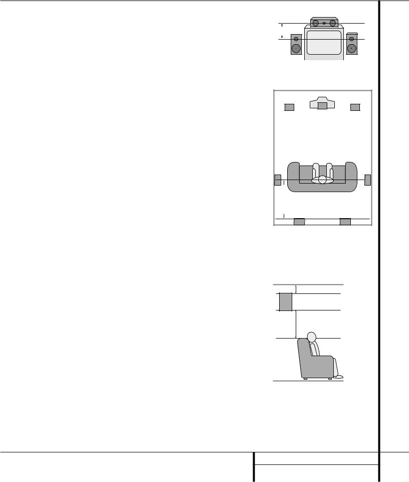
System Configuration
When all audio, video and system connections have been made, there are a few configuration adjustments that must be made. A few minutes spent to correctly configure and calibrate the unit will greatly add to your listening experience.
Speaker Selection and Placement
The placement of speakers in a multichannel home-theater system can have a noticeable impact on the quality of sound reproduced.
No matter which type or brand of speakers is used, the same model or brand of speaker should be used for the front left, center and front right speakers. This creates a seamless front soundstage and eliminates the possibility of distracting sonic disturbances that occur when a sound moves across mismatched front channel speakers.
Speaker Placement
Depending on the type of center channel speaker in use and your viewing device, place the center speaker either directly above or below your TV, or in the center behind a perforated front projection screen.
Once the center channel speaker is installed, position the left front and right front speakers so that they are as far away from one another as the center channel speaker is from the preferred listening position. Ideally, the front channel speakers should be placed so that their tweeters are no more than 24" above or below the tweeter in the center channel speaker.
Depending on the specifics of your room acoustics and the type of speakers in use, you may find that imaging is improved by moving the front left and front right speakers slightly forward of the center channel speaker. If possible, adjust all front loudspeakers so that they are aimed at ear height when you are seated in the listening position.
Using these guidelines, you’ll find that it takes some experimentation to find the correct location for the front speakers in your particular installation. Don’t be afraid to move things around until the system sounds correct. Optimize your speakers so that audio transitions across the front of the room sound smooth, and that sounds from all speakers appear to arrive at the
listening position at the same time (without delay from the center speaker compared to the left and right speakers).
Surround speakers should be placed on the side walls of the room, at or slightly behind the listening position. The center of the speaker should face into the room. The speakers should be located so that the bottom of the cabinet
is at least two feet higher than the listeners’ ears when the listeners are seated in the desired area.
If side-wall mounting is not practical, the speakers may be placed on a rear wall, behind the listening position. Again, they should be located so that the bottom of the cabinet is at least two feet higher than the listeners’ ears. The speakers should be no more than six feet behind the rear of the seating area.
Subwoofers produce nondirectional sound, so they may be placed almost anywhere in a room. Actual placement should be based on room size and shape and the type of subwoofer used. One method of finding the optimal location for a subwoofer is to begin by placing it in the front of the room, about six inches from a wall, or near the front corner of the room. Another method is to temporarily place the subwoofer at your normal listening position, and then walk around the room until you find a spot where the subwoofer sounds best. Place the subwoofer in that spot. You should also follow the instructions of the subwoofer’s manufacturer, or you may wish to experiment with the best location for a subwoofer in your listening room.
System Setup
Once the speakers have been placed in the room and connected, the remaining steps in the setup process are to program the AVR 310’s bass management system for the
type of speakers used in your system, calibrate the output levels, and set the delay times used by the surround sound processor.
You are now ready to power up the AVR 310 to begin these final adjustments.
1.Plug the Power Cable ° into an unswitched AC outlet.
Center Front Speaker
No more than 24" 
Left Front |
|
Right Front |
Speaker |
|
Speaker |
A) Front Channel Speaker Installation with Direct-View TV Sets or Rear-Screen Projectors
|
|
TV or Projection Screen |
|
|
Left Front |
Center Front |
Right Front |
|
Speaker |
||
|
Speaker |
Speaker |
|
|
|
||
No more than 6 feet |
when rear-mounted speakers are used |
Optional Rear-Wall Mounting |
|
|
|
|
B) The distance between the left and right speakers should be equal to the distance from the seating position to the viewing screen. You may also experiment with placing the left and right speakers slightly forward of the center speaker.
At least 6 inches from ceiling
At least 2 feet
17 SYSTEM CONFIGURATION
 Loading...