


 Loading...
USER MANUAL
Ethernet Option
OPC-G11S-ETN
For
GE Fuji AF-300G11/P11
Firmware Version 1.XXX
Document SDM-7583-006
Version 1.0 - Dec 19, 2003
HMS Industrial Networks
Germany |
|
|
|
! |
+ 49 |
- 721 - 96472 - 0 |
sales-ge@hms-networks.com |
||
Japan |
+ 81 |
– 45 - 478 -5340 |
sales-jp@hms-networks.com |
|
Sweden |
+ 46 |
- 35 |
- 17 29 20 |
sales@hms-networks.com |
U.S.A |
+ 1 - 773 |
- 404 - 2271 |
sales-us@hms-networks.com |
|

|
Table of Contents I |
Table of Contents |
|
Table of Contents.................................................................................................................. |
I |
About This Manual ............................................................................................................ |
IV |
How To Use This Manual......................................................................................................................................................... |
IV |
Important User Information..................................................................................................................................................... |
IV |
Related Documentation............................................................................................................................................................. |
IV |
Revision List................................................................................................................................................................................ |
IV |
Conventions Used in This Manual............................................................................................................................................ |
V |
About the OPC-G11S-ETN................................................................................................... |
1 |
Key Features.................................................................................................................................................................................. |
1 |
General........................................................................................................................................................................................ |
1 |
Ethernet Global Data (EGD)..................................................................................................................................................... |
1 |
EtherNet/IP............................................................................................................................................................................... |
1 |
Modbus/TCP ............................................................................................................................................................................. |
1 |
EtherNet/IP Network Overview............................................................................................................................................... |
2 |
Ethernet Global Data (EGD) Network Overview.................................................................................................................. |
2 |
Modbus/TCP Network Overview............................................................................................................................................. |
3 |
Applicable Inverters ..................................................................................................................................................................... |
4 |
Installation ............................................................................................................................ |
5 |
Receiving Inspection.................................................................................................................................................................... |
5 |
Installation of Option Card......................................................................................................................................................... |
6 |
Installation Checklist.................................................................................................................................................................... |
7 |
Installation and Configuration ............................................................................................. |
8 |
Module Overview......................................................................................................................................................................... |
8 |
Network Connection ................................................................................................................................................................... |
8 |
Status Indicators ........................................................................................................................................................................... |
9 |
LED 1 – Ethernet Link/Activity.............................................................................................................................................. |
9 |
LED 2 – Module Status............................................................................................................................................................. |
9 |
LED 3 – Network Status .......................................................................................................................................................... |
9 |
Assigning a Network Address................................................................................................................................................... |
10 |
Example Using HICP .............................................................................................................................................................. |
11 |
Bus Configuration Parameters.................................................................................................................................................. |
12 |
Operation Configuration Parameters....................................................................................................................................... |
12 |
Fault Detection and Action....................................................................................................................................................... |
13 |
EGD .................................................................................................................................... |
14 |
Configuration .............................................................................................................................................................................. |
14 |
Data Messages............................................................................................................................................................................. |
15 |
Command Messages................................................................................................................................................................... |
15 |
Configuration Messages............................................................................................................................................................. |
16 |
Modbus/TCP...................................................................................................................... |
17 |

|
Table of Contents II |
Addressing................................................................................................................................................................................... |
17 |
Commands .................................................................................................................................................................................. |
17 |
Exception Codes......................................................................................................................................................................... |
17 |
Timeout........................................................................................................................................................................................ |
18 |
EtherNet/IP ....................................................................................................................... |
19 |
IO Connection............................................................................................................................................................................ |
19 |
Idle action .................................................................................................................................................................................. |
19 |
Example PLC configuration ...................................................................................................................................................... |
19 |
Explicit Messaging...................................................................................................................................................................... |
21 |
Get Attribute Single Example ................................................................................................................................................... |
21 |
Set Attribute Single Example .................................................................................................................................................... |
23 |
Electronic Data Sheet (EDS) File ............................................................................................................................................ |
24 |
Appendix A - EGD, EtherNet/IP IO Format.................................................................... |
25 |
Data Consumed by the Drive ................................................................................................................................................... |
25 |
Run Command Word ................................................................................................................................................................ |
25 |
Frequency Setting (S01) ............................................................................................................................................................. |
25 |
Data Produced by the Drive ..................................................................................................................................................... |
26 |
Operation Status Monitor 1 ....................................................................................................................................................... |
26 |
Operation Status Monitor 2 ....................................................................................................................................................... |
26 |
Output Frequency Monitor (M06).............................................................................................................................................. |
27 |
Appendix B - Drive Parameters.......................................................................................... |
28 |
Parameter List ............................................................................................................................................................................. |
28 |
Data Format Specification......................................................................................................................................................... |
33 |
Data Format [1]: Integer Data (Positive): Min. Unit 1 ............................................................................................................ |
33 |
Data Format [2]: Integer Data (Positive, Negative): Min. Unit 1 ............................................................................................. |
33 |
Data Format [3]: Decimal Data (Positive): Min. Unit 0.1....................................................................................................... |
33 |
Data Format [4]: Decimal Data (Positive, Negative): Min. Unit 0.1........................................................................................ |
33 |
Data Format [5]: Decimal Data (Positive): Min. Unit 0.01..................................................................................................... |
33 |
Data Format [6]: Decimal Data (Positive, Negative): Min. Unit 0.01 ..................................................................................... |
33 |
Data Format [7]: Decimal Data (Positive): Min. Unit 0.001................................................................................................... |
33 |
Data Format [8]: Decimal Data (Positive, Negative): Min. Unit 0.001 ................................................................................... |
34 |
Data Format [10]: Alarm Code............................................................................................................................................... |
34 |
Data Format [11]: Capacity Code............................................................................................................................................ |
34 |
Data Format [12]: Index Data (ACC/DEC Time, Display Coefficient).................................................................................. |
35 |
Data Format [14]: Operation Command ................................................................................................................................... |
35 |
Data Format [15]: Universal Output Terminal ......................................................................................................................... |
35 |
Data Format [16]: Operating State ........................................................................................................................................... |
36 |
Data Format [17]: Type Code.................................................................................................................................................. |
36 |
Data Format [18]: Code Setting (1 – 4 Figures)........................................................................................................................ |
36 |
Data Format [19]: Amperage Value Decimal Data (Positive) ................................................................................................... |
37 |
Data Format [20]: Transmission Error Code ............................................................................................................................ |
37 |
Data Format [21]: Auto Tuning............................................................................................................................................... |
37 |
Appendix C – Ethernet/IP Objects.................................................................................... |
38 |
Identity Object, Class 0x01 ....................................................................................................................................................... |
39 |
Services ...................................................................................................................................................................................... |
39 |
Class Attributes......................................................................................................................................................................... |
39 |
Instance Attributes..................................................................................................................................................................... |
39 |
Assembly Object (Class 0x04) .................................................................................................................................................. |
40 |
Services ...................................................................................................................................................................................... |
40 |
Class Attributes......................................................................................................................................................................... |
40 |
Instance Attributes, Instance/Connection Point 0x03 (3d).......................................................................................................... |
40 |

|
Table of Contents III |
Instance Attributes, Instance/Connection Point 0x64 (100d) |
..................................................................................................... 40 |
Instance Attributes, Instance/Connection Point 0x65 (101d) ..................................................................................................... |
40 |
Instance Attributes, Instance/Connection Point 0x96 (150d) ..................................................................................................... |
40 |
Fuji Vendor Specific Object (Class 0x64) ............................................................................................................................... |
41 |
Services ...................................................................................................................................................................................... |
41 |
Class Attributes......................................................................................................................................................................... |
41 |
Instance Attributes..................................................................................................................................................................... |
41 |
TCP/IP Interface Object (Class 0xF5).................................................................................................................................... |
42 |
Services ...................................................................................................................................................................................... |
42 |
Class Attributes......................................................................................................................................................................... |
42 |
Instance Attributes..................................................................................................................................................................... |
42 |
Ethernet Link Object (Class 0xF6) .......................................................................................................................................... |
43 |
Services ...................................................................................................................................................................................... |
43 |
Class Attributes......................................................................................................................................................................... |
43 |
Instance Attributes..................................................................................................................................................................... |
43 |
Appendix D - EGD Exchanges .......................................................................................... |
44 |
Exchange C1 ............................................................................................................................................................................... |
44 |
Exchange P1................................................................................................................................................................................ |
44 |
Exchange P2................................................................................................................................................................................ |
44 |
Exchange P3................................................................................................................................................................................ |
45 |

About This Manual IV
About This Manual
How To Use This Manual
This manual is intended to provide a good understanding of the functionality of the OPC-G11S-ETN module. This manual only covers the Ethernet communication module, for more info about the drive’s capabilities refer to the drive manual. For more information about a specific fieldbus contact the respective fieldbus organization.
Important User Information
The data and illustrations found in this document are not binding. We reserve the right to modify our products in line with our policy of continuous product development. The information in this document is subject to change without notice and should not be considered as a commitment by HMS Industrial Networks AB. HMS Industrial Networks AB assumes no responsibility for any errors that may appear in this document.
AnyBus® is a registered trademark of HMS Industrial Networks AB. All other trademarks are the property of their respective holders.
Related Documentation
Document |
Author |
EtherNet/IP specification |
ODVA |
Open Modbus/TCP specification |
Schneider Electric |
Ethernet Global Data, Protocol specification |
GE Fanuc / GE Industrial Systems |
AF-300G11 Instruction Manual |
GE Fuji |
AF-300P11 Instruction Manual |
GE Fuji |
Revision List
Revision |
Date |
Author |
Chapter |
Description |
1.0 |
Dec 19, 2003 |
MaH |
All |
Document created |

About This Manual V
Conventions Used in This Manual
The following conventions are used throughout this manual:
•Numbered lists provide sequential steps
•Bulleted lists provide information, not procedural steps
•The term ‘module’ is used when referring to the OPC-G11S-ETN
•Hexadecimal values are written in the format NNNNh or 0xNNNN, where NNNN is the hexadecimal value.

About the OPC-G11S-ETN 1
About the OPC-G11S-ETN
The OPC-G11S-ETN Ethernet adapter interfaces the G11 or P11 drive to an Ethernet network. The module support three different communication protocols: EtherNet/IP, Ethernet Global Data (EGD), and Modbus/TCP. It is not recommended that more than one protocol is used for controlling the drive at the same time.
Key Features
General
•10/100 Mbps operation
•DHCP support
•Supports HICP (Host IP Configuration Protocol)
•FTP server for configuration and firmware upgrade
Ethernet Global Data (EGD)
•Implements EGD class 3 functionality
•Data messages (Exchanges)
•Command messages
•Configuration messages
EtherNet/IP
•IO data connection
•EtherNet/IP explicit messaging
Modbus/TCP
•Supports 8 simultaneously connections
•Configurable time-out

About the OPC-G11S-ETN 2
EtherNet/IP Network Overview
EtherNet/IP is an industrial networking standard that takes advantage of commercial off-the-shelf Ethernet communication chips and physical media. IP, stands for 'industrial protocol' and is what distinguishes this network. Unlike many options in the industrial Ethernet crowd, EtherNet/IP uses an open protocol at the application layer. Further, more than one vendor or organization backs EtherNet/IP. It is the only standard supported by three networking organizations: ControlNet International (CI), the Industrial Ethernet Association (IEA) and the Open DeviceNet Vendor Association (ODVA)
For further information:
ODVA
1099 Highland Drive, Suite A
Ann Arbor, Michigan 48108
Phone: 1-734-975-8840
Fax: 1-734-922-0027
Email: odva@odva.org
http://www.odva.org
Ethernet Global Data (EGD) Network Overview
Ethernet Global Data (EGD) supports the ability to share information between controllers (nodes) in a networked environment. EGD allows one controller, referred to as the producer of the data, to simultaneously send information to any number of peer controllers (consumers) at a fixed periodic rate.
In addition, EGD supports a set of commands for accessing data and protocol information on EGD nodes. EGD also defines a mechanism for sharing configuration information among nodes.
EGD protocol messages are categorized as command, data, or configuration messages.
Command messages can be used to monitor and control the operation of EGD on the destination node. Data messages are individually configured to send a sample of data at a fixed periodic rate. Each data message that a node sends or receives is associated with a specific identifier, which uniquely defines the configuration of the data sample. This configuration is referred to as an exchange. EGD allows the configuration of exchanges that are sent to a single destination address (IP Unicast addressing), a group of addresses (IP Multicast addressing), or to all EGD nodes (IP Broadcast addressing). An assigned set of 32 IP Multicast addresses has been defined for use by applications requiring the transmission of data exchanges to a group of nodes.
EGD configuration messages are transferred using HTTP on the connection based TCP/IP transport layer, utilizing XML as a data abstraction layer.

About the OPC-G11S-ETN 3
Modbus/TCP Network Overview
Modbus/TCP was invented by Modicon/Group Schneider and is today is one of the most popular protocols embedded inside the TCP/IP frames of Ethernet.
The Modbus protocol was first published back in the 1970's and has been adopted by users and vendors alike in the industrial automation world. No changes have been made to the protocol itself but changes have been made in the way or the rate that messages are sent in order to fulfill the real-time needs of industrial applications. This has given us Modbus/TCP.
Modbus/TCP basically embeds a Modbus frame into a TCP frame in a simple manner. This is a connectionoriented transaction, which means every query expects a response.
This query/response technique fits well with the master/slave nature of Modbus, adding to the deterministic advantage that Switched Ethernet offers industrial users.
For further information:
The Modbus Organization
PO Box 628
Hopkinton, MA 01748-0628
Phone: 508-435-7170
http://www.modbus.org
|
|
|
About the OPC-G11S-ETN 4 |
|
Applicable Inverters |
|
|
|
|
|
|
|
|
|
|
Item |
Description |
|
|
|
Inverter type |
AF-300G11/P11 |
|
|
|
Compatible inverter Model number |
The two last digits of the model number should be B1 or later |
||
|
|
Example: 6KG1123X1B1 |
|
|
|
Minimum inverter ROM version |
Up to 22kW (30HP) |
S08000 |
|
|
|
30 kW (40HP) and above |
H08004 |
|
Note: This product can only be used for Inverters with ROM version numbers greater than or equal to the versions shown above.
1.Check the ROM number of your Inverter as follows, using the inverter keypad.
2.Check that the Inverter Operation monitor (Operation mode) screen is displayed.
3.Press the [PRG] key of the Inverter once.
4.Select the "5. MAINTENANC" with the cursor and press the [FUNC/DATA] key.
5.Press the down cursor key to increment the display at the MAINTENANC screen. Finally, the ROM number is shown in the maintenance information, as indicated by the display "INV=Hxxxxx or Sxxxxx".
The maintenance and inspection items are similar to the Inverter unit, for detail refer to the Inverter Instruction Manual.
Installation 5
Installation
Receiving Inspection
Confirm the following items upon a receipt.
1.The model number matches your purchase order?
2.Check the model number printed on the circuit board.
Model: OPC – G11S – ETN
Option Type
ETN = Ethernet Interface Option
Inverter type
G11S = AF-300 G11/P11 Series
3. Inspection for damage during transportation. Report damage to transportation carrier.
Installation 6
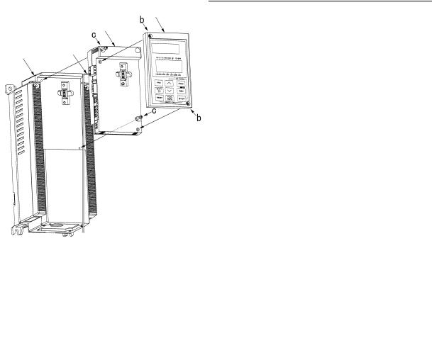
Installation of Option Card
Please follow the installation procedure described as follows. Please install or detach the option after turning off the input power supply of the inverter and confirming the charge lamp (CHARGE or CRG) is gone out.
The shape, the dimensions and the position of the charge lamp of the inverter are different by each capacity.
|
Keypad |
Keypad |
|
Option Unit |
|
Top Cover |
|
|
|
|
|
Inverter Unit |
|
Inverter Unit PE Line |
Step 1 |
Charge Lamp |
Step 2 to 4 |
Step 1
Loosen two screws (M4) at a and remove the top cover. Loosen two screws (M3) at b and detach the keypad panel. (For the 30kW[40HP] and above inverters, the keypad panel can be detached if the front cover is removed and the screws loosened at b.)
Step 2
Reassemble the top cover, push-in the option unit and secure it with two screws (M3) at c.
Step 3
Secure the keypad panel to the option unit with two screws at b.
Step 4
Connect the ground cable to the PE terminal of the option unit (The rightmost screw terminal, besides the RJ45 Ethernet connector).

Installation 7
Installation Checklist
After installation and wiring, check the following items.
•The wiring is correct.
•No loose wires or screws remain inside the Inverter.
•The screws and terminals are all tight.
•There are no loose threads of wires at terminals that may contact other terminals.
•Inverter parameters such as H30, o27, o28, o31 to o40, are set correctly. (H30: Link Active/Inactive, o27 and o28: for network loss action, o31 to o40: for fieldbus specific options)
Installation and Configuration 8
Installation and Configuration
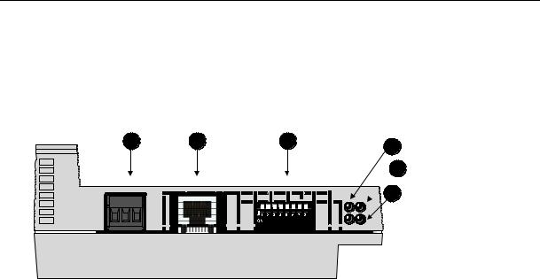
Module Overview
A |
B |
C |
1 |
|
|
|
2
 3
3
|
|
|
|
|
|
|
|
|
|
|
|
|
|
|
|
|
|
|
|
|
|
|
|
|
|
|
|
|
|
|
|
|
|
|
|
|
|
|
|
|
|
|
|
|
|
|
|
|
|
|
|
|
|
|
|
|
|
|
|
|
|
|
|
|
|
|
|
|
|
|
|
|
|
|
|
|
|
|
|
|
|
|
|
|
|
|
|
|
|
|
|
|
|
|
|
|
|
|
|
|
|
|
|
|
Figure |
|
Description |
|
|
||||||||||
A |
|
PE Connector |
|
|
||||||||||
B |
|
RJ45 Ethernet connector |
|
|
||||||||||
C |
|
Network address switch |
|
|
||||||||||
1-3 |
|
|
|
|
|
|
|
|
LED indicators |
|
|
|||
Network Connection
Connect the module to a 10 or 100 Mbps Ethernet network.
LED 1 lit green when the module detects link, the LED will flash when the module is receiving/transmitting data on the network.
Default, auto negotiation will be used for speed and duplex. If speed and duplex settings need to be configured manually, i.e., no link is established, see the bus configuration parameters.
|
|
|
Installation and Configuration 9 |
|
Status Indicators |
|
|
||
|
LED 1 – Ethernet Link/Activity |
|
|
|
|
|
|
|
|
|
Color |
LED state |
Description |
|
|
Green |
On |
The module sense link |
|
|
|
Off |
The module does not sense link |
|
|
|
Flash |
The module is receiving/transmitting data on Ethernet |
|
|
LED 2 – Module Status |
|
|
|
|
|
|
|
|
|
LED state |
Device State |
Description |
|
|
Steady Off |
No power |
- |
|
|
Steady Green |
Device operational |
The module has an Ethernet/IP connection OR has a |
|
|
|
|
healthy EGD exchange OR has a Modbus/TCP |
|
|
|
|
connection. |
|
|
Flashing Green |
Standby |
The module has no active data exchange but is ready to |
|
|
|
|
be controlled. |
|
|
Flashing Red |
Minor fault |
A recoverable minor fault has been detected. E.g., a |
|
|
|
|
connection time out or EGD exchange in unhealthy state. |
|
|
Steady Red |
Major fault |
A major internal error has been detected. E.g., hardware |
|
|
|
|
fault or invalid drive type detected. |
|
|
Flashing Green/Red |
Self-test |
The module is performing its power up testing. |
|
|
LED 3 – Network Status |
|
|
|
|
|
|
|
|
|
LED state |
Network State |
Description |
|
|
Steady Off |
No power or |
The module has no power or no IP address is configured. |
|
|
|
no IP address |
|
|
|
Flashing Green |
No connections |
There are no Ethernet/IP connections established to the |
|
|
|
|
module. |
|
|
Steady Green |
Connected |
The module has at least one established Ethernet/IP |
|
|
|
|
connection. |
|
|
Flashing Red |
Connection timeout |
One or more of the EtherNet/IP connections, where this |
|
|
|
|
module is the target, has timed out. This state is only left if |
|
|
|
|
all timed out connections are re-established or if the |
|
|
|
|
module is reset. |
|
|
Steady Red |
Duplicate IP |
The module has detected that its IP address is already in |
|
|
|
|
use. |
|
|
Flashing Green/Red |
Self-test |
The module is performing its power up testing. |
|

Installation and Configuration 10
Assigning a Network Address
When the module is connected to the network it must me assigned a unique IP address on the network. There are four methods available for setting the IP address:
Method |
Description |
Comment |
Network address switch |
The module will use the IP address |
Must be set before power-on. This |
|
192.168.0.X where X is set with the |
configuration can only be used in a |
|
network address switch. The address |
private network. |
|
is set binary with DIP1 as MSB. |
|
DHCP |
The module will automatically receive |
DHCP is enabled by default. |
|
the configuration from a DHCP server. |
|
HICP |
Use “Anybus IPconfig” software to find |
HICP can be disable, see bus config |
(Windows program) |
the module on the network and |
parameters. |
|
configure it. |
|
EtherNet/IP |
Send IP parameters to the TCP/IP |
Module needs to be restarted before |
|
interface object- |
new configuration will be used. |

Installation and Configuration 11
Example Using HICP
Install “Anybus IPconfig” software on a PC with MS Windows. The software is located on the diskette delivered with the module and can also be downloaded from the web at http://www.hms-networks.com.
1.Start the configuration program and hit the Scan button, the module(s) shall appear in the window: If the module does not appear, make sure that it is connected to the same network and that it has link.
2.Double click on the line with the module you want to configure. If you have several nodes connected to the network, the MAC address shall match the MAC address that is printed on the side of the module. The following window will open:
3.Enter the desired settings and turn DHCP off. The settings can optionally be protected by a password. Hit set and the module is configured. The DNS settings are not used in this product.
Loading...