

Page 1

Gate w a y
ALR 9250R
User’s Guide
Part #8504180 A MANSYS US9250R USR GDE R0 4/99
Page 2

Notices
Copyright © 1999 Gateway 2000, Inc.
All Rights Reserved
610 Gateway Drive
N. Sioux City,SD 57049 USA
AllRig htsReserv ed
This publication is protected by copyright and all rights are reserved. No part of it may bereproduced
or transmitted by any means or in any form, without prior consent in writing from Gateway 2000.
The information in this manual has been carefully checked and is believed to beaccurate. Howev er,
changes are made periodically.These changes are incorporated in newer publication editions.
Gateway 2000 may improveand/or change products described in this publication at any time. Due to
continuing system improvements, Gateway 2000 is not responsible for inaccurate information which
may appear in this manual. For the latest product updates, consult the Gateway 2000 web site at
www.gateway .c om. In no eventwill Gateway2000 be liable fordirect, indirect, special, exemplary,
incidental, or consequential damages resulting from any defect or omission in this manual, evenif
advised of the possibility of such damages.
In the interest of continued product development, Gateway2000 reserves the right to make
improvements in this manual and the products it describes at any time, without notices or obligation.
T rademark Acknowledgments
AnyKey ,black-and-white spot design, ColorBook, CrystalScan, Destination, EZ Pad, EZ Point, Field
Mouse, Gateway 2000, HandBook, Liberty,TelePath,Vivitron, stylized “G” design, and “You’vegot a
friend in the business” slogan are registered trademarks and “All the big trends start in South Dakota”
slogan, GAT EWAY ,and Gateway Solo are trademarks of Gateway 2000, Inc. Intel, Intel Inside logo,
and Pentium are registered trademarks and MMX is a trademark of Intel Corporation. Microsoft, MS,
MS-DOS, and Windows are trademarks or registered trademarks of Microsoft Corporation. All other
product names mentioned herein are used for identification purposes only,and may bethe trademarks
or registered trademarks of their respective companies.
ii
Copyright © 1999 Advanced Logic Research, Inc. (ALR)
All Rights Reserved
9401 Jeronimo
Irvine, CA 92618 USA
AllRig htsReserv ed
This publication is protected by copyright and all rights are reserved. No part of it may bereproduced
or transmitted by any means or in any form, without prior consent in writing from ALR.
The information in this manual has been carefully checked and is believed to beaccurate. Howev er,
changes are made periodically.These changes are incorporated in newer publication editions. ALR
may improve and/or change products described in this publication at any time. Due to continuing
system improvements, ALR is not responsible for inaccurate information which may appear in this
manual. For the latest product updates, consult the ALR web site at www.alr.com.InnoeventwillALR
be liable for direct, indirect, special, exemplary, incidental, or consequential damages resulting from
any defect or omission in this manual, even if advised of the possibility of such damages.
In the interest of continued product development, ALR reserves the right to make improvements in this
manual and the products it describes at any time, without notices or obligation.
T rademark Acknowledgments
ALR is a registered trademark of Advanced Logic Research, Inc. All other product names mentioned
herein are used for identification purposes only,and may be the trademarks or registered trademarks
of their respective companies.
Page 3

Contents
Preface ..................................................................... ......... ......vii
Conventions used in t his gui de... .... .. ..... .. .... .. .. ..... .. .... .. .. .... .. ..... .. .. .... . viii
Safety in structio ns.......... ..... .. .. .... .. .. ..... .. .. .... .. .. ..... .. .. .... .. .. .... ... .. .... .. .. .... ix
Additional inf ormation source s.... .... ... .. .... .. .. .... ... .. .... .. .. .... .. ... .... .. .. .... .. xi
Chapter 1: Getting Started . .................. .......... .................. ....... 1
System acce ss......... .. .... .. .. ... .... .. .. .. .... ... .. .... .. .. .. ..... .. .. .. .... .. .. ..... .. .. .. .... .. .. . 2
Static electr icity precautions............. .... ...... ..... .... ...... .... ....... .... .... ... 2
Opening the system.......... .... ...... ..... .... ...... ..... .... ...... .... ....... .... .... ..... 2
Closing the syste m. .. .. ..... .. .. .... .. .. ..... .. .. .... .. .. ..... .. .. .... .. .. ..... .. .. .... .. .. ... 5
Installing the CPU drawer......... ...... ..... .... ...... .... ..... ...... .... ....... .... .... ...... . 7
Inspecting the contents....... .... .. ..... .. .. .... .. .. ..... .. .. .... .. .. .... ... .. .... .. .. .... . 7
Installing the CPU drawer i n the ra ck..... .... ... .... .. .. .... .. ..... .. .. .... .. .... . 8
Connecting peripher als...... ...... ..... .... ...... .... ....... .... .... ....... .... .... ..... 12
Using an autoswitc her.......... .... .. ..... .. .. .... .. .. ..... .. .. .... .. .. ..... .. .. .... .. .. . 14
Powering up the system.. ....... .... .... ....... .... ...... .... ..... ...... .... .... ....... .... ..... 15
Looking things ove r..... .... .. .. .... .. ... .... .. .. .... .. ... .... .. .. .... .. .. ..... .. .. .... .. . 15
Verifying your conf iguratio n..... ..... .. .. .... .. .. ..... .. .. .... .. .. ..... .. .. .... .. .. . 16
Troubleshooting guidelines..... ....... .... ...... ..... ...... .... ...... ..... ...... .... . 16
Completing the inst allatio n............. .... .. .. .... ... .. .... .. .. .... .. ... .... .. .. .... . 16
Chapter 2: System Features ................................... ..............21
Basic architec ture..... .... .... ....... .... ...... ..... .... ...... ..... .... ...... .... ....... .... .... ... 22
Front panel............ .. .. .... .. .. ..... .. .. .. .... .. ... .. .... .. .. .... ... .. .. .... .. .. .. ..... .. .. .... .. .. . 23
Dual redundant 400- Watt power supplies....... .... .. .. .... .. ..... .. .. .... .. . 23
Switches......... .. .. .... .. .. ... .... .. .. .... .. ... .. .... .. .. .. ..... .. .. .... .. .. .. ..... .. .. .. .... .. . 24
3.5-inch diskette drive.......... .... .. ... .... .. .. .... .. ... .... .. .. .... .. .. ..... .. .. .... .. . 24
CD-ROM drive .... .. .. .. ..... .. .. .... .. .. ... .... .. .. .. .... ... .. .... .. .. .. .... ... .. .. .... .. .. . 24
Storage bays... .. .. .... .. ..... .. .. .... .. .. ..... .. .. .... .. .. ..... .. .. .... .. .. .... ... .. .... .. .. ... 24
LED indicators........ ..... .... ...... .... ....... .... .... ....... .... ...... .... ..... ...... .... . 25
Rear panel......... .. .. .... .. .. .. ..... .. .. .. .... .. .. ..... .. .. .. .... .. ... .. .... .. .. .... .. ... .. .... .. .. .. . 26
Power connector s............. .. .... .. .. ..... .. .. .... .. .. ..... .. .. .... .. .. ..... .. .. .... .. .. . 26
I/O ports............. .. .... .. ... .. .... .. .. .. ..... .. .. .... .. .. .. ..... .. .. .. .... .. .. ..... .. .. .. .... . 27
Expansion slot cover plates........ ....... .... ...... ..... ...... .... ....... .... ...... ... 27
System board.......... .... .. .. ..... .. .. .. .... .. .. ... .... .. .. .... .. ... .. .... .. .. .. .... ... .. .... .. .. .. . 28
Drive controlle rs a nd connec tors.............. ..... .. .. .... .. .... .. ... .... .. .... .. . 29
Contents i
Page 4

System jumpe rs... .. .... .. .. ..... .. .. .. .... .. .. .. ..... .. .. .... .. .. ... .... .. .. .. .... ... .. .... . 31
Miscellaneous c onnector s..... .. .. .... .. .. ..... .. .. .... .. .. ..... .. .. .... .. .. ..... .. .. . 32
Expansion slot connectors........... .... ....... .... ...... ..... .... ...... .... ..... ..... 33
Memory module c onnector......... .. .... ... .. .... .. .. .... ... .. .... .. .. .... ... .. .... . 34
System manage ment c onnectors.......... .. .. .... .. .. ..... .. .. .... .. .. ..... .. .. ... 34
Back panel I /O connect ors. .. .. .... .. .. .... ... .. .... .. .. .... ... .. .... .. .. .... ... .. .... . 36
Processors a nd re lat ed connectors... .. ..... .. .. .... .. .. ..... .. .. .... .. .. ..... .. .. . 38
Power connector s........ .. ..... .. .. .... .. .. .... ... .. .... .. .. .... ... .. .... .. .. .... ... .. .... . 40
Operating systems........ .... ...... ..... .... ...... .... ....... .... .... ....... .... .... ....... .... ... 41
Chapter 3: Components .........................................................43
Introduction........... ..... .. .. .... .. .. ..... .. .. .... .. .. ..... .. .. .... .. .. ..... .. .. .... .. .. ..... .. .. ... 44
Processors.... .... .. .. .. ..... .. .. .... .. .. ... .... .. .. .. .... .. ... .... .. .. .. .... ... .. .. .... .. .. ..... .. .. .. . 44
Replacing t he proc essor..... .... .. .. .... .. .. ..... .. .. .... .. .. ..... .. .. .... .. .. ..... .. .. . 44
Installing another proce ssor......... .... ....... .... ...... ..... ...... .... ....... .... ... 48
Installing a VRM. .... .. .. .... ... .. .... .. .. .... .. ... .... .. .. .... .. ... .... .. .. .... .. ... .... .. . 52
Memory............. .. ..... .. .. .. .... .. .. ... .... .. .. .... .. .. ... .... .. .. .. .... ... .. .... .. .. .. ..... .. .. .. . 54
DIMM installation sequence....... ...... ..... ...... .... ....... .... ...... ..... ...... . 55
System memory add ressing. .... .. .. .... .. ... .... .. .. .... .. ... .... .. .. .... .. ... .... .. . 55
Memory configurat ion....... ...... .... ...... ..... .... ...... ..... ...... .... .... ....... ... 56
Removing the memor y modul e..... .... ... .. .... .. .. .... ... .. .... .. .. .... ... .. .... . 56
Removing DIMMs..... .... ... .. .... .. .. .... .. ... .... .. .. .... .. ... .... .. .. .... .. ... .... .. . 58
Installing DIMMs... .... ....... .... ...... .... ..... ...... .... .... ....... .... ...... ..... .... . 59
Installing the memory module. ...... ....... ...... .... ....... .... ...... .... ....... ... 60
Expansion cards............. .... .... ....... .... .... ....... .... ...... .... ..... ...... .... ....... .... . 62
Power Supply Modules.. .... .. ..... .. .. .... .. .. .... ... .. .... .. .. .... ... .. .... .. .. .... ... .. .... . 64
Storage ba ys.......... ..... .. .. .... .. .. ... .... .. .. .. .... .. ... .... .. .. .. .... ... .. .. .... .. .. ..... .. .. .. . 66
5.25-inch devi ce............ ..... .... ...... .... ....... .... .... ....... .... .... ...... ..... ..... 67
3.5-inch device s.... .. .... .. .. ..... .. .. .... .. .. ..... .. .. .... .. .. ..... .. .. .... .. .. ..... .. .. ... 68
RAID cage (optional)... ..... ...... .... .... ....... .... ...... ..... .... ...... .... ..... ..... 70
Chapter 4: BIOS S etup .................... ............................ ..........77
ii Gateway ALR 9250RUser’s Guide
Introduction........... ..... .. .. .... .. .. ..... .. .. .... .. .. ..... .. .. .... .. .. ..... .. .. .... .. .. ..... .. .. ... 78
Using BIOS Setup........ .... ...... ..... .... ...... .... ....... .... .... ....... .... .... ....... .... ... 79
If you cannot access Setup... .... .... ...... ..... .... ...... ..... ...... .... .... ....... ... 80
Starting BI OS Setup... .. ..... .. .. .... .. .. .... ... .. .... .. .. .... ... .. .... .. .. .... ... .. .... . 80
Setup key c ommands......... .... .. .. .... .. .. ..... .. .. .... .. .. ..... .. .. .... .. .. ..... .. .. . 81
Special di splay ite ms.... .. ... .... .. .. .... .. .. ..... .. .. .... .. .. ..... .. .. .... .. .. ..... .. .. . 81
Main menu. .... ... .. .... .. .. .. ..... .. .. .. .... .. .. ..... .. .. .. .... .. .. ... .... .. .. .... .. ... .. .... . 82
Page 5

Advanced menu..... .... ....... .... .... ..... ...... .... .... ..... ...... .... .... ....... .... .... . 84
Security menu...... .... ....... .... .... ....... .... .... .... ....... .... .... .... ....... .... .... ... 89
Server menu....... .. .... .. ... .. .... .. .. .. ..... .. .. .... .. .. .. ..... .. .. .. .... .. .. ..... .. .. .. .... . 90
Boot menu.. .. .. .... .. .. .. ..... .. .. .... .. .. .. ..... .. .. .. .... .. ... .... .. .. .. .... .. ... .. .... .. .. ... 92
Exit menu..... .... .. .. .. .... ... .. .... .. .. .. ..... .. .. .. .... .. .. ..... .. .. .. .... .. .. ... .... .. .. .... . 94
Upgrading the BIOS..... .. ..... .. .... .. .. .... ... .. .... .. .. .... ... .. .... .. .. .... .. ... .... .. .. .... . 95
Preparing for the upgrade......... ..... .... ...... .... ....... .... .... ....... .... ...... ... 95
Upgrading the BIOS.. ... .... .. .. .... .. ... .... .. .. .... .. ... .... .. .. .... .. .. ..... .. .. .... .. . 97
Recovering the BIOS........... .. .. ..... .. .. .... .. .. ..... .. .. .... .. .. .... ... .. .... .. .. ... 98
Changing the B IOS la nguage............. .. .. .... ... .. .... .. .. .... .. ... .... .. .. .... . 99
Chapter 5: The Ser verSetup Utility ............... .................. ...101
Introduction .. .. ..... .. .. .... .. .. ..... .. .. .... .. .. ..... .. .. .... .. .. ..... .. .. .... .. .. .... ... .. .... .. .. . 102
Using the Server Setup Utility............. .... .... ...... ..... ...... .... .... ....... .... ... 103
When to run the SSU.... .. .... .. .. .... ... .. .... .. .. .... ... .. .... .. .. .... .. ... .... .. .. ... 104
Running the SSU...... .... .. ..... .. .. .... .. .. ..... .. .. .... .. .. ..... .. .. .... .. .. .... ... .. .... .. .. . 105
Customizing the S SU....... ..... .. .. .... .. .. ..... .. .. .... .. .. ..... .. .. .... .. .. ..... .. .. .... .. . 107
Launching a t ask......... .. .. ..... .. .. .... .. .. ..... .. .. .... .. .. ..... .. .. .... .. .. .... ... .. .... .. .. . 108
SSU add-ins.......... .. .. .... .. .. ..... .. .. .... .. .. ..... .. .. .... .. .. ..... .. .. .... .. .. ..... .. .. .... .. . 109
Resource configuration add- in........ .... ...... ..... ...... .... ...... ..... ...... ... 109
Multiboot options add-in.... ...... ....... .... ...... ..... ...... .... ...... ..... ...... ... 113
Security add-in. .... ...... ..... .... ...... ..... .... ...... .... ..... ...... .... .... ....... .... ... 113
System event l og vie wer add-in........ .. .. .... .. ..... .. .. .... .. .... ... .. .... .. ... 115
Sensor data record ma nager add-In............ ..... .... ...... .... ....... .... ... 116
Field rep laceable uni t manager add- In.............. .. .... .. .. ..... .. .... .. .. . 117
Exiting the SSU.......... .... .. ... .... .. .. .... .. ... .... .. .. .... .. ... .... .. .. .... .. .. ..... .. .. .... . 119
Chapter 6: Other Utilities ................................ .................. ...121
Introduction .. .. ..... .. .. .... .. .. ..... .. .. .... .. .. ..... .. .. .... .. .. ..... .. .. .... .. .. .... ... .. .... .. .. . 122
Power-on self test........... .. ..... .. .. .... .. .. ..... .. .. .... .. .. ..... .. .. .... .. .. ..... .. .. .... .. . 124
Emergency management port conso le... ...... ...... ..... ...... .... ....... .... ...... . 126
How the EMP console works ......... ...... .... ..... ...... .... .... ....... .... .... . 127
EMP console re quirem ents............. .. .... .. .. ..... .. .. .... .. .. .... ... .. .... .. .. . 129
Setting up the ser ver for t he EMP....... .. .. .... ... .. .... .. .. .... .. ... .... .. .. ... 130
Main EMP console window ......... ...... .... ....... .... .... ...... ..... ...... .... . 132
Server control ope rations. ...... .... ....... .... ...... ..... .... ...... .... ..... ...... ... 134
Phonebook....... .. .... .. ..... .. .. .... .. .. ..... .. .. .... .. .. ..... .. .. .... .. .. .... ... .. .... .. .. . 137
Management plug-ins ....... .... .... ....... .... ...... ..... .... ...... .... ....... .... .... . 138
FRU and SDR loa d uti lity........... .... .. ... .... .. .. .... .. ... .... .. .. .... .. .. ..... .. .. .... . 142
Contents iii
Page 6

When to run the F RUSDR l oad utili ty......... .. .... ..... .. .... .. .... ... .... . 142
What you need to do.......... .. .. .... .. .. .... ... .. .... .. .. .... ... .. .... .. .. .... ... .. ... 142
How to use t he FR USDR load uti lity... .. .... .. .. .... ... .... .. .. .... .. ..... .. . 143
Cleaning up and exiting............. .... .... ....... .... .... ....... .... ...... ..... .... . 147
Using the fir mware upda te ut ility..... .... .. ..... .. .... .. .... .. ... .... .. .... .. .. ..... .. . 148
Using the Symbios SCSI ut ility.. .... .. .... .. ..... .. .... .. .. .... ... .... .. .. .... .. ..... .. . 149
Chapter 7: Troubleshooting ...................... ................... ........151
Introduction........... ..... .. .. .... .. .. ..... .. .. .... .. .. ..... .. .. .... .. .. ..... .. .. .... .. .. ..... .. .. . 152
Computer virus notice.. ...... .... ....... .... ...... ..... .... ...... .... ..... ...... .... ....... ... 152
Troubleshooting checklist... ..... ...... .... .... ....... .... ...... ..... .... ...... .... ....... . 154
Verifying the conf igurati on....... .. .... .. ... .... .. .. .... .. ... .... .. .. .... .. ... .... . 154
Troubleshooting guidelines........... ....... .... ...... .... ....... .... ...... ..... ... 154
Solving problems......... ...... .... ..... ...... .... .... ....... .... .... ....... .... .... ....... .... . 155
Resetting the sy stem... .. .. ..... .. .. .... .. .. ..... .. .. .... .. .. ..... .. .. .... .. .. ..... .. .. . 155
Initial system startup.......... ...... .... ...... ..... .... ...... ..... .... ...... .... ....... . 155
Running new applica tion softwar e.... ..... .. .. .... .. ..... .. .. .... .. .... ... .. ... 156
New problems............. .. .. ..... .. .. .... .. .. ..... .. .. .... .. .. ..... .. .. .... .. .. ..... .. .. . 157
More problem-solving pr ocedures....... .... .. .. .... .. ..... .. .. .... .. ..... .. .. . 158
Problems a nd sol utions.......... .. .. .... .. .. ..... .. .. .... .. .. ..... .. .. .... .. .. ..... .. . 160
Error message s and cod es......... .. .... .. .. .... .. ... .... .. .. .... .. ... .... .. .. .... .. ... .... . 166
POST codes and port-80h codes.......... .... .. .. .... .. ..... .. .. .... .. ..... .. .. . 166
POST error codes and messages.......... .... ...... .... ....... .... .... ....... ... 170
Appendix A: System BoardJumpers ................. .................173
Appendix B: Regulatory Compliance Sta tements ...............181
iv Gateway ALR 9250R User’s Guide
Setting t he jumpe rs ... .... .. .. .... .. ... .... .. .. .... .. .. ..... .. .. .... .. .. ..... .. .. .... .. .. ..... .. . 174
Changing a jum per s etting..... .... .. .... .. ..... .. .. .... .. ..... .. .. .... .. .... ... .. ... 175
CMOS Clear jumper....... ....... .... ...... ..... .... ...... .... ....... .... .... ....... ... 176
Password Clear jumper...... ...... .... ...... ..... .... ...... ..... .... ...... .... ....... . 177
Recovery Boot jumper.... ..... ...... .... ....... .... .... ...... ..... ...... .... ..... ..... 178
Acronyms and abbr evi ations.......... .. .. .... .. ... .... .. .. .... .. ... .... .. .. .... .. ... .... . 182
Terms and def initi ons.... .. .. .... ... .. .... .. .. .... .. ... .... .. .. .... .. ... .... .. .. .... .. ... .... . 186
FCC notice... .... .... ..... ...... .... .... ....... .... .... .... ....... .... .... ..... ...... .... .... ....... . 189
Industry Canada noti ce.......... ..... .. .. .... .. .. ..... .. .. .... .. .. ..... .. .. .... .. .. ..... .. .. . 190
CE notice........... .. .. ... .... .. .. .... .. ... .. .... .. .. .. .... ... .. .... .. .. .. ..... .. .. .. .... .. .. ..... .. . 190
VCCI notice.... .... .. ... .... .. .. .... .. ... .... .. .. .... .. .. ..... .. .. .... .. .. ..... .. .. .... .. .. ..... .. . 191
Australia/New Zea land noti ce.......... .. .. .... ... .. .... .. .. .... ... .. .... .. .. .... ... .. ... 191
Page 7

Index ................ ......... .......... ......... ......... .......... ..................... 193
Contents v
Page 8

vi Gateway ALR 9250R User’s Guide
Page 9
Pref ace
Conventions used in t his gui de........ .. .... .. ..... .. .... .viii
Safety in structio ns............. .... .. ... .... .. .. .... .. ... .... .. .. ...ix
Additional infor mation source s.... .. .. .... .. ..... .. .. .... .. .xi
Page 10
Con ventions used in this guide
Throughout this guide, you will see the follo wing conv entions:
Manual Conventions
Convention Description
ENTER Keyboard key names ar e printed in small
capitals.
C
TRL+ALT+DEL A plus sign indicatesthatthe keysmustbe
pressed simultaneously.
Setup Commands to be ent ered, options to
select,and messages that appear on your
monitor are printed in bold.
User’s Guide
Namesof publicationsandfilesareprinted
in italic.
Note:
Caution!
Warning!
!
Important!
A note informs you of special circumstances.
A cautionwarnsyouofpossible damage to
equipment or loss of data.
A warning indicates the possibility of personal injury.
An import ant notifies you of an important
point or an essential st ep which may prevent the system or process from working.
viii Gateway ALR 9250R User’s Guide
Page 11

Safety instructions
Observe the following safety inst ructions when using your system:
• Follow all instructions mar ked on the syst em and in the
documentation.
• When the system is turned of f, a small amount of elec trical current
still runs through the system. Alwa ys unplug the system from the
electrical outlet before cleaning the system or opening the co ver .
• Do not use this product near water or a heat source, such as a
radiator or heat register .
• Do not spill anything on or into the system. The best wa y to avoid
spills is t o a v oid e ating or drinki ng near the se rver.
• Make sure y ou set u p the system on a stab le work surface.
• Openings in the system cabinet a re pro vided for ve ntilation. Do not
block or cov er these openings. Make sure you pro vide adequate
space around the system for ventilation when you set up yo ur work
area. Never insert objects of any kind into the system venti lation
slots.
• Use the voltage setting for your area. The voltage selec tor switch is
set at the factory to the correct voltage.
Warning!
!
Do not attempt to service
thesystem yourselfexcept
as explained elsewhere in
the system documentation.
Adjust only those controls
covered in the instructions.
Opening or removing
covers marked “Do Not
Remove” may expose you
to dangerous electrical
voltages or otherrisks.
• This system is equipped with 3-wire grounding plugs (plugs with a
grounding pin). These plugs onl y fit into grounded power outlet s.
This is a safety feature. Do not defeat the purpose of the grounding
pin. If you are unab le to insert the plug i nto t he outle t, co ntact an
electrician to replace the outlet.
• Do not walk on the pow er cord or allo w anything to rest on it.
• If you use an extension cord with this system, make sure the total
ampere ratings of the components plugged into the extension cord
do not exceed the extension cord ampere rating. Also, the total
ampere requirements for all products plugged into the wall outlet
must not exce ed 15 amper es.
Preface ix
Page 12

• There is a danger of explosion if the CMOS (complementary
metal-oxide se miconductor) battery is r eplaced inc orrectl y.
Replace the battery with the same or equivalent type recommended
by the manufacturer . Dispose of used batteries according to the
manufacturer’s instructions.
• Unplug the system f rom the w all outl et and refer servicing to
qualified personnel if:
• The power cor d or plug is damaged.
• Liquid has been spilled into the sys tem.
• The system does not operate properly when the opera ting
instructions are foll owed.
• The system was dropped or the cabine t is da maged.
• The system’s performance changes.
x Gateway ALR 9250RUser’s Guide
Page 13

Additional inf ormation sources
Along with this manual, you can find additional information by using the
Gatew a y Support Cent er
Access the Gate wa y Support Center at www.gatewa y .c om/support to access
information about your system or ot her Gate w a y products. Some types of
information you can access are:
• Hardware dri ver (including BIOS) and softw are application
updates
• An expanded glossary
• Technical tips
• Service agreement information
• Technical documents and component inf ormation
• Frequentl y Asked Questions (FAQs)
• Online access to technical support
Preface xi
Page 14

xii Gateway ALR 9250R User’s Guide
Page 15

Chapter 1:
Getting Started
System acce ss............ .. .... .. .. .. ..... .. .. .... .. .. .. ..... .. .. .. ....2
Static electric ity precautions................ ...... .... .. 2
Opening the system............... .... ...... ..... ...... .... .. 2
Closing the system...... ...... ....... .... ...... ..... ...... ....5
Installing the CPU drawer....... ....... .... ...... ..... ...... ....7
Inspecting the conte nts........ .... .. .. .... .. ..... .. .. .... ..7
Installing the C PU dra wer i n the rack........ .. ....8
Connecting peripherals ..... ..... ...... .... ....... .... ....12
Using an autoswitcher........... .... ...... ..... ...... ....14
Powering up the system....... .... ....... .... ...... ..... ...... ..15
Looking things ove r.. .... .. ..... .. .... .. .. .... ... .... .. .. ..15
Verifying your configurati on............... ...... ....16
Troubleshooting guidelines. ...... .... ....... ...... ....16
Completing the install ation......... ...... ..... ...... ..16
Page 16

Caution!
Power down the system
and disconnect both power
cords before proceeding
with system access.
Installing any component
while the power is on may
causep ermanent damage
to the system.
System access
System access is pr o vide d b y a hinged top co v er. All system components
can be accessed through t his cover .
Static electricity precautions
Static electricity can damage computers and other sensiti ve electronic
equipment. Precauti ons such as those described belo w should b e tak en
before opening the system draw er , or touching any of the components, and
prior to removing an y new component from its protecti ve packaging.
Caution! Prevent Static-Electricity Damage
Static Electricit y Prev ention s
1. WEAR A GROUNDING WRIST STRAP (available at most electronic
stores).
2. T urn off the system pow er.
3. T ouch the back of the power suppl y fan, located on the back of the case.
4. UNPLUG ALL CORDS FROM WALL OUTLET .
5. Remo v e t he sys tem case cover .
Static Electri city Pr ecautio ns
• Avoid static-causing surfaces such as pla stic and styrofoam in y our work
area.
• Remove t he parts from their ant istati c bags onl y w hen you are ready to use
them. Do not lay parts on the outside of antistatic bags since only the
inside provi des antis tatic prot ection.
• Always hold ca rds b y their e dges and their metal mounting brac ket. Avoid
touching components on the ca rds and th e edge connectors th at connec t to
expansion slots.
• Never slide cards or other parts ov er any surface.
Openin g thesystem
Depending on your purpose, you ma y need to open only the front portion of
the top cov er, or you may need to remo ve the top cov er entirel y . Foll ow the
instructions specific to the task you want to accomplish as indicated in each
section.
2 Gateway ALR 9250R User’s Guide
Page 17
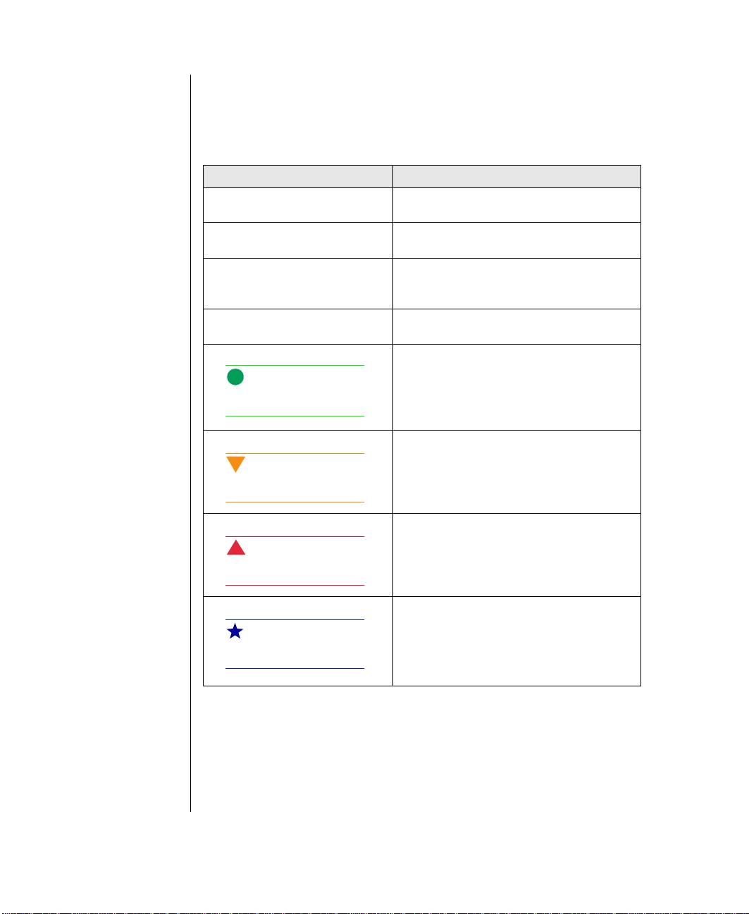
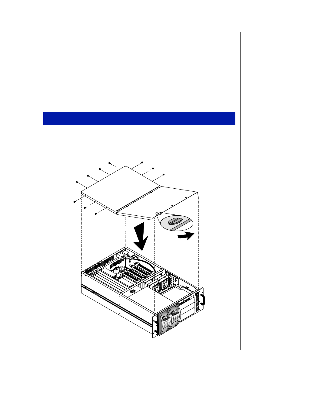
Opening the topcover
The top cover is hinged so y ou can open it to acce ss t he internal
components without removi ng it entirely.
T o open the top cover
1. Po w er do wn the system.
2. While observing the static elect ricity precautions on pa ge 2, turn each
of the three sl otte d retainer s 90 degrees cou nterclockwise. See t he
illustration Opening the Top Co ver below .
Slotted
retainers
Opening the Top Cover
3. Lift the lid co vering the front portion of t he system to access the pow er
supply subs ystem, the fans, the hard dis k dr iv e mounting bra cket, t he
3.5-inch disk ette drive, the data cab l es, and t he RAID bay backplane.
9250r_19
Chapter 1: Getting Started 3
Page 18
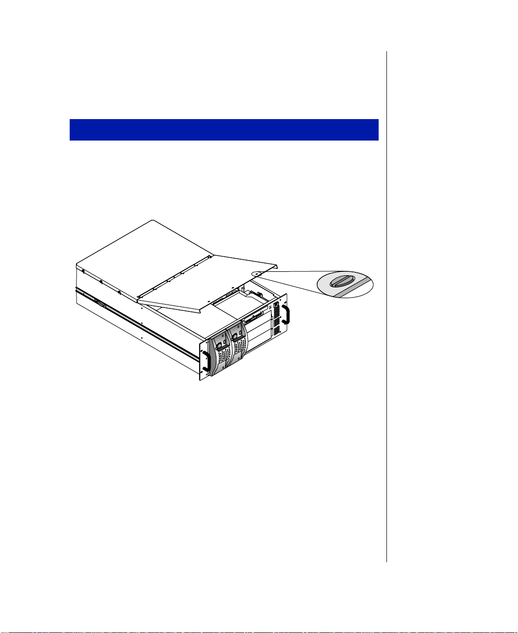
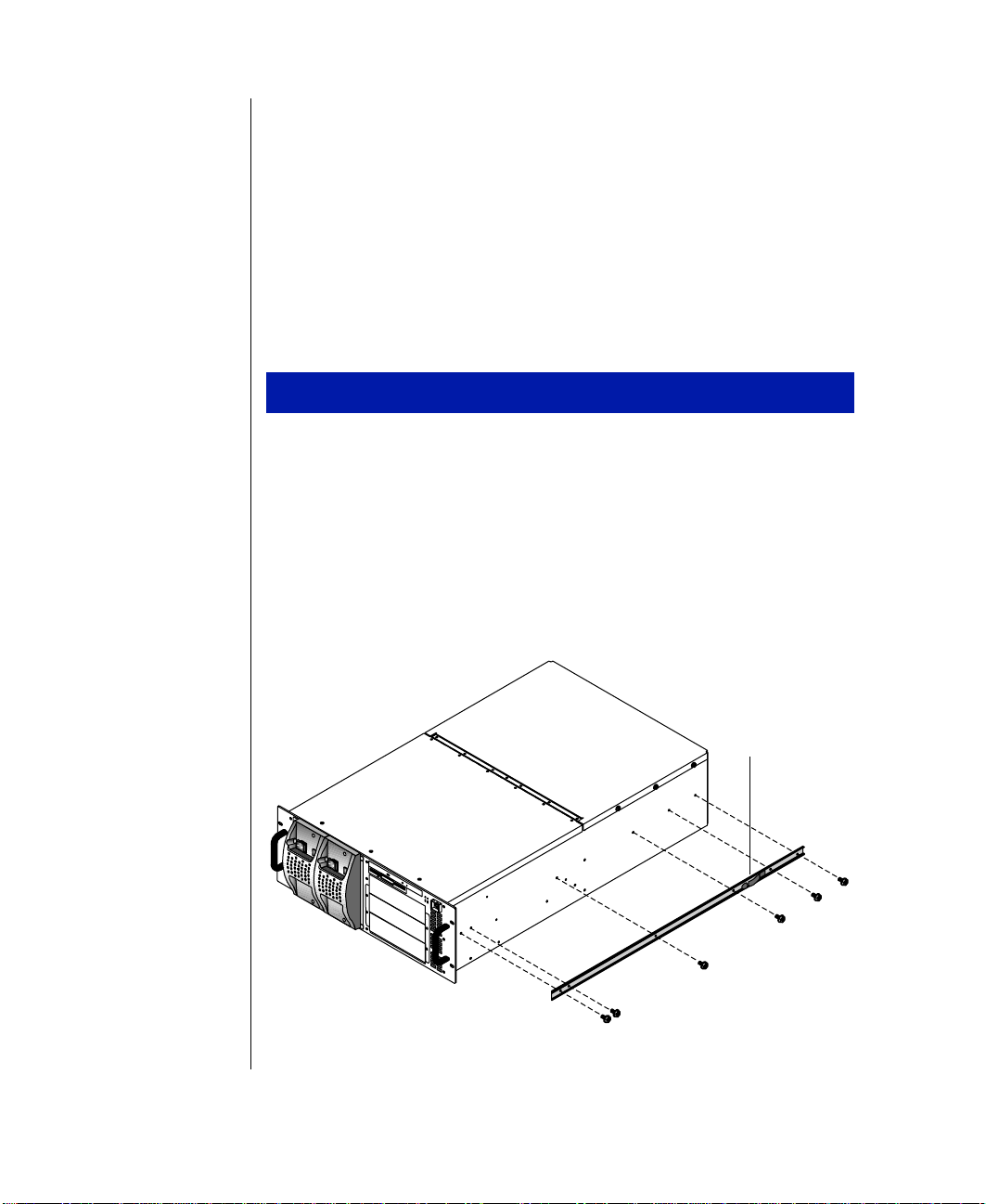
Removingthe topcover
The back portion of the draw er holds the syst em board and the add-in cards.
Remove the top cov er to access these components.
T o remove the top cover
1. Remove t he three sc re ws f rom each s ide of the t op cover and the f our
screws from the bac k of t he top c o v er. See the ill ustrati on Removing
the T op Co ver belo w .
T opcover
Slotted
retainers
2. Remove the top cov er .
4 Gateway ALR 9250R User’s Guide
9250r_10
Removing the Top Cover
Page 19
Closing the system
Before closing the system, verify that all connectors and boards are
properly install ed and firmly seated.
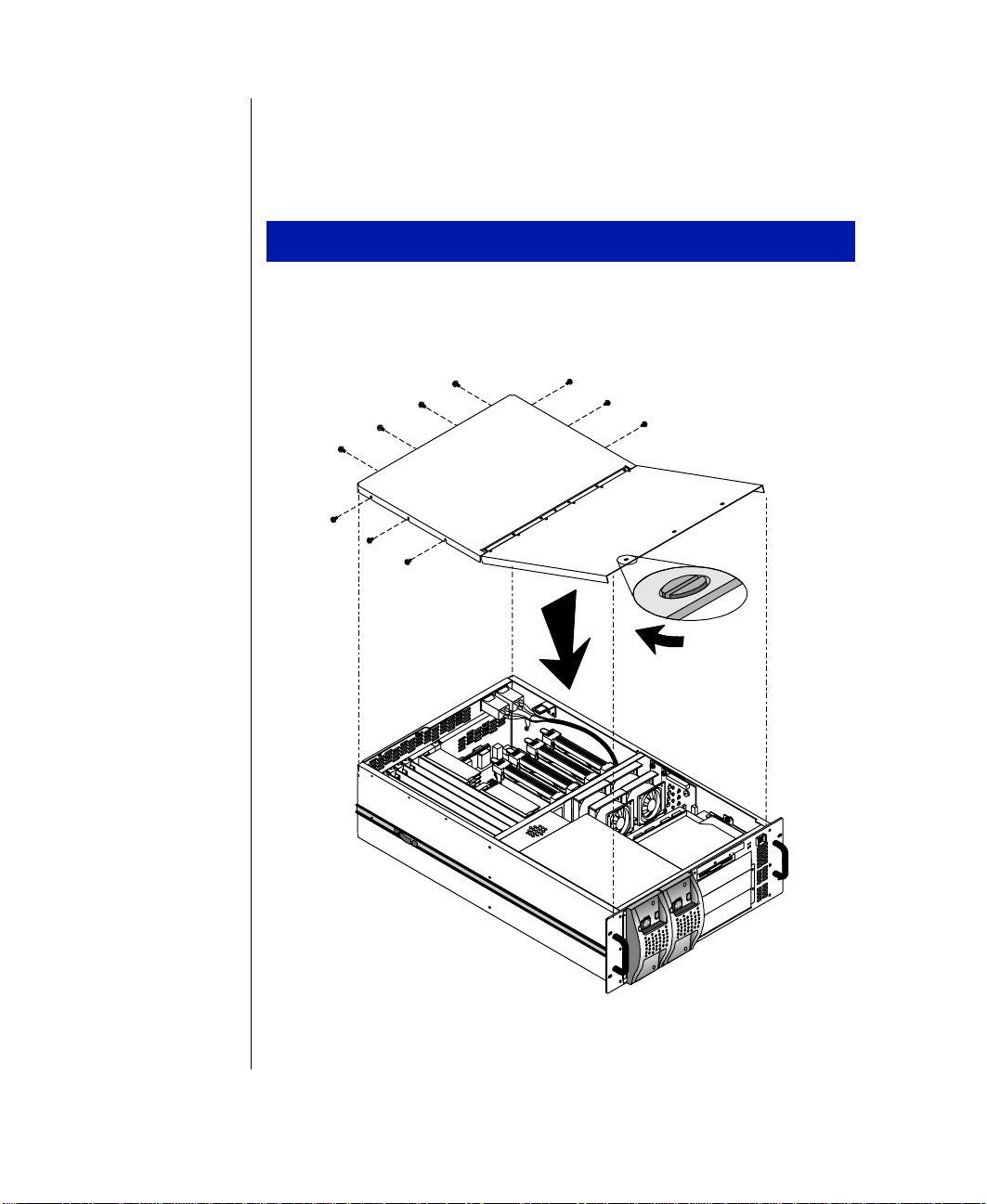
Reinstalling the topcover
After you hav e completed the procedures in volving the back portion of the
draw er , replac e the top cove r .
To replace the top cover
1. Position the top cove r on the chassis, aligning the three holes on each
side and four holes in back. See the illustration Reinstalling the T op
Cove r be lo w.
Reinstalling the T op Co ver
9250r_11
Chapter 1: Getting Started 5
Page 20

2. Replace the scre ws remo v ed w hen the t op cover was remo v ed (thr ee
on each side and four in back).
3. T urn t he thr ee sl otted ret ainers 90 degrees clockwise to sec ure t he
front portion of t he top c o v er in pl ace.
6 Gateway ALR 9250R User’s Guide
Page 21

Installing the CPU drawer
If the rails hav e not been mounted on the processor drawer at the factory,
you must install them. The brackets must be installed in the rack.
Requirements for i nstallat ion of the dr a w er a re liste d belo w.
• This CPU dra w er is an 4U syste m, meaning that it r equires 7
vertical inches (1.75" x 4") of rack space for installation. Check
your rack configuration to make sure you have at least this much
space. You may have to remo ve bla nk panels or rearrange existing
draw ers to pro vide enough clearance.
• Protect your system from extreme temperature and humidity.
Position y our rack aw a y from direct sunlight, heater ducts, and
other heat-generating objects .
• Keep y our syst em a w ay from equipment that gene rates m agnetic
fields. Even a telephone placed too c losel y to the system may
cause interference.
• Your new system drawe r is configured for AC operation. Protect it
against AC line spik es by using a 3-prong, 110 V or 220 V
(depending on the voltage supplied in your localit y), and an AC
surge contr ol outlet station. The s ystem re quires tw o se parate AC
outlets (one per pow er supply) .
Inspect ing the contents
Unpack the carton and inspe ct t he cont ents. Sta ndard systems inclu de the
following ite ms:
Note:
Drawer heightsare
measured in “U’s.” Each U
is 1.75
", measured
vertically on the rack.
• System Drawer
• P ow er Cab les
• User’s Guide
• Software Utilitie s (Diskettes or CD)
Check the packing list to ensure all equipment and associated manuals are
included in y our sh ipment. Inspect ev erything ca refull y. If you suspect an y
damage from shipping, contact technical support immediately
.
Important!
Keepthe product carton
and foam packing, in case
youhavetoshipthe
system.Ifyoureturnthe
system in different
packaging, your warranty
maybevoided.
Chapter 1: Getting Started 7
Page 22
Installingt heCPUdra werinth e rack
These procedures assume that the mounting rails hav e not been installed on
the dra w er at the factory and that the brack ets have not been insta lled i n the
rack. If these procedures hav e been completed , you can skip them.
Installingthe mountingrails
The mounting rails are provided in the accessory kit. If they ha ve already
been installed on the system dra wer, y ou can ski p thi s procedure.
T o install the mounting rails
1. After unpacking the system draw er , note that the side rails come
preassembled with the mounting rails. Prior to mounting the side rails
to the system chassis, they must be remov ed from the mounting rails.
Remove t he side r ails f rom the mounting r ails b y depressi ng the
retention clips and sli ding t hem of f.
2. Mount the side r ails on the syst em chassi s wit h the t w elv e scre ws
provide d. See the illustration Mounting the Side Rails belo w. The
retention clips should go tow ard the rear of the cabinet.
8 Gateway ALR 9250R User’s Guide
Retention clips
9250r_08
Mounting the Side Rails
Page 23
3. Position the 4U drawe r template in the cabinet/rack so that the side
matches the corresponding side you wish t o inst all.
4. Mark the scre w hole l ocations on t he v ertical mounting stri ps i n the
cabinet, as sho wn on the template. The marks will locate the mounting
holes of the r ail bra cket s and fr ont p anel.
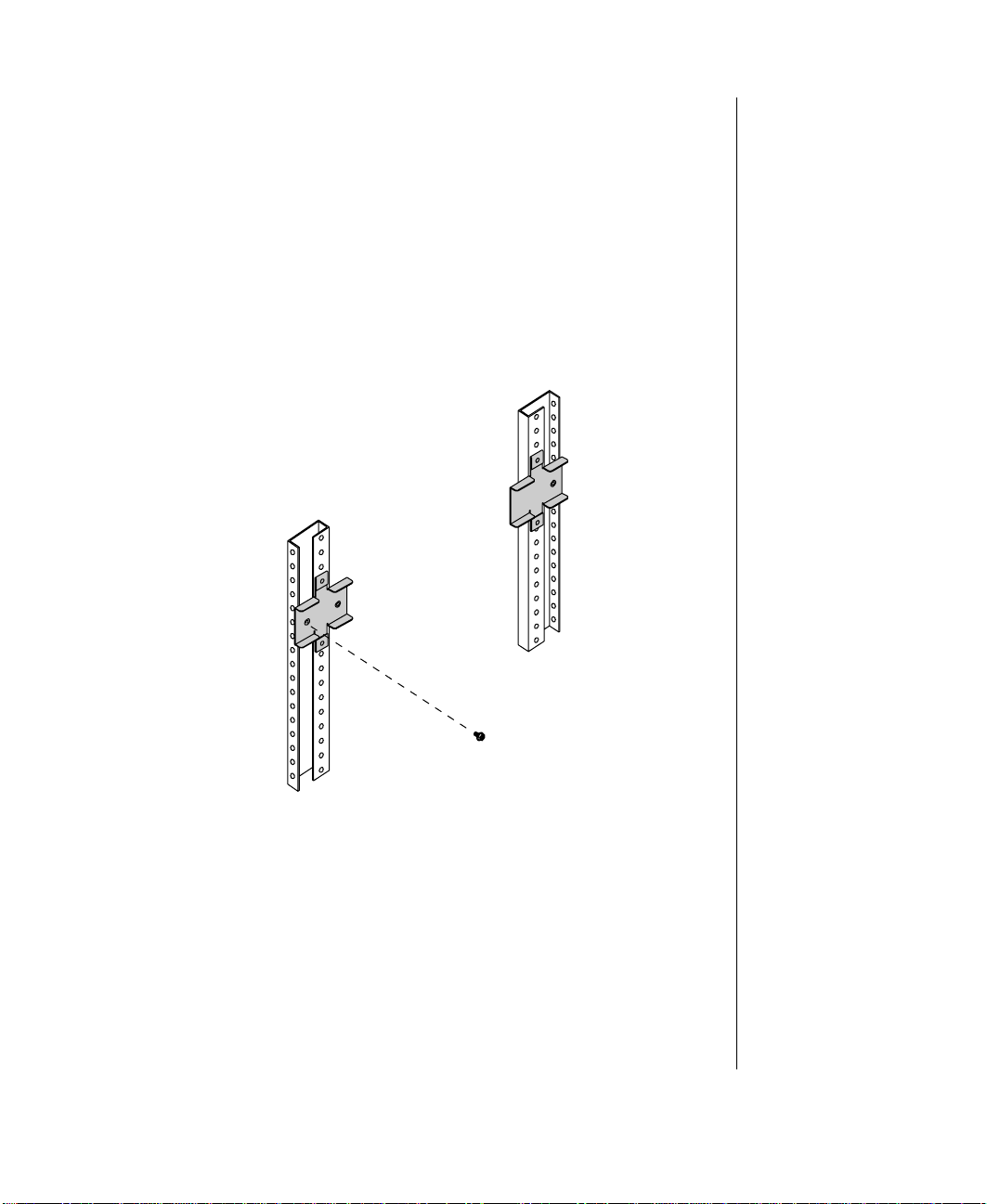
5. Attach the front bracke t t o the fr ont cabinet v ertical mounting strip
using tw o screws.
6. Attach the rear bracke t to the re ar ca binet v ertical mounting strip. See
the illustration Mounting the Brackets on the Cabinet belo w .
Mounting the Brac kets on the Cabinet
7. Repeat Steps 4 through 6 to mount t he second rail.
9250R_04
Chapter 1: Getting Started 9
Page 24
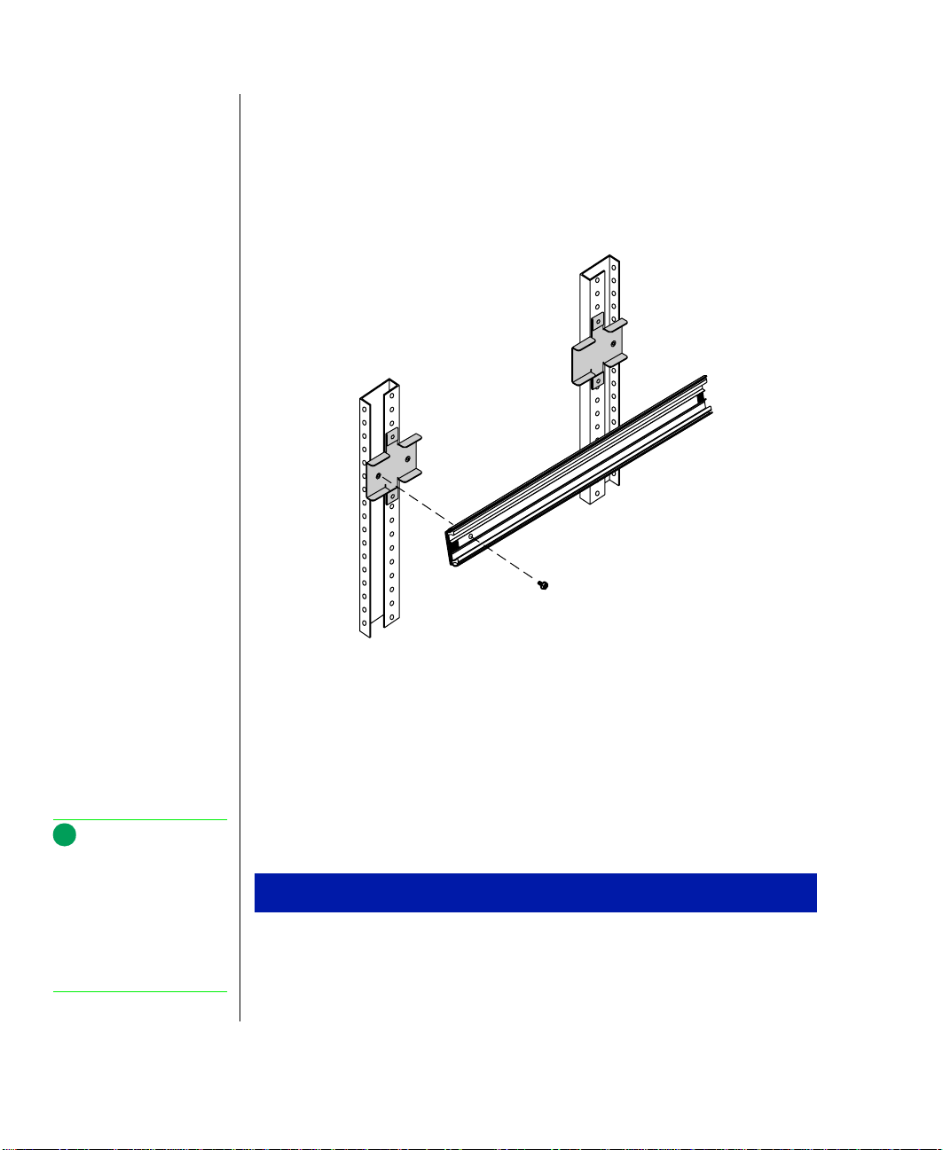
8. T o se cure t he rea r of the ra il, sli de the inner rai ls forw ard to g ain
access to the mounting holes. The latch may lock the rail into place.
Release the latch to allo w the rails to slide freel y. T o secure the front of
the rail, slide the inner rail so that the opening aligns with the
mounting holes. See the illustration Attaching the Cabinet Mounting
Rails belo w. V erify t hat the i nner ra ils slide fr eely.
9250R_05
Mounting the CPUdrawerin thecabinet
When the rails and the br ack ets are i nstal led, you are r eady to instal l th e
draw er in t he cabine t. Check the sys tem spe cifications for the weight of the
Note:
The CPU drawer is heavy .
T oprevent injury and
possible damage to the
equipment, we
recom mended thatyou get
help when trying to mount
the drawer into the cabinet.
10 Gateway ALR 9250R User’s Guide
draw er and use appropriate precautions wh en performing the installation.
1. Pull the inner cabinet mounting rails (in the cabinet) all the wa y
Attaching the Cabinet Mounting Rails
T o mount the drawer in the cabinet
forward until the retaining latch es lock the rails in the “out” position.
Page 25
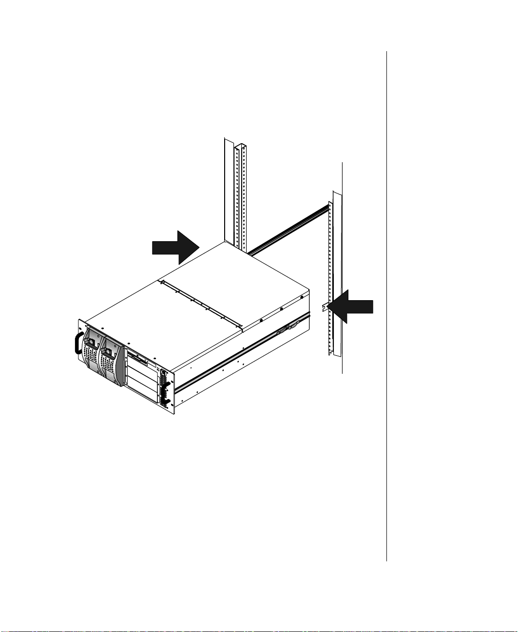
2. Lift the CPU draw er to the same height as the mounting rails and align
the rails on the draw er with the cabinet mounting rails.
3. Insert the side rails on the CPU drawer into the cabinet mounting rails
and push the drawer e ve nly into the c abinet until the latc hes on the
draw er rails lock. See the illustrat ion Installing the Draw er belo w.
Installing the Dr aw er
9250r_15
Chapter 1: Getting Started 11
Page 26
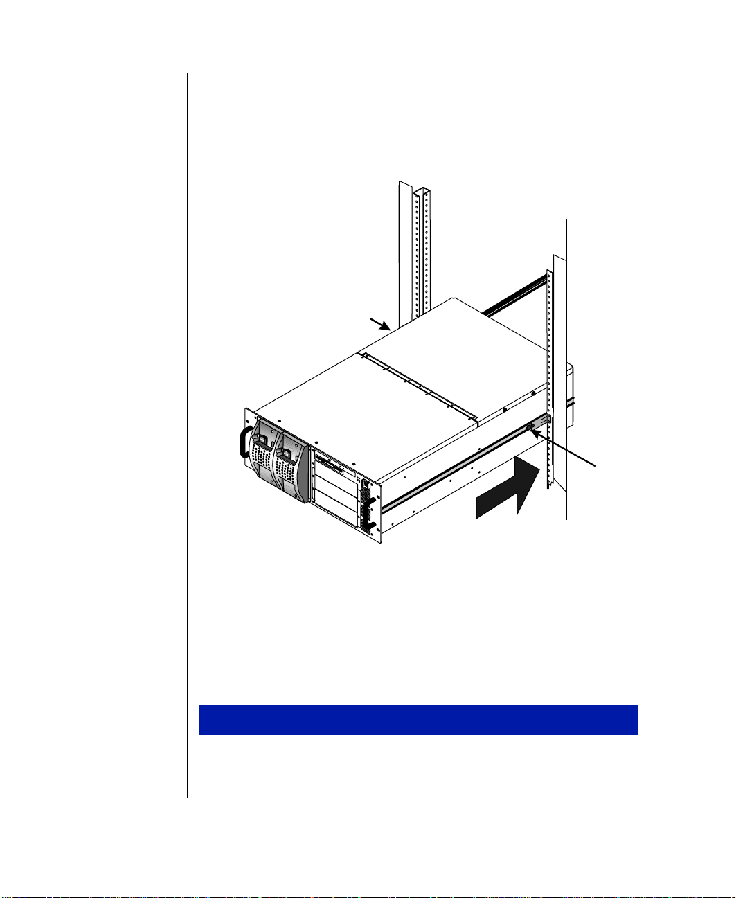
4. Press the latches on both side rails of the CPU drawer and push the
draw er into the cabinet until the front panel touches the vertical
mounting rails. S ee the illus tration Cabine t Rai l Retainin g Latches
below. The draw er ma y move reluc tantly at first. How ev er , it should
move smoothl y, without binding or restriction, ther eafter.
Latch
Latch
Connectin g peripherals
Refer to “Connecting P eripherals” on page 13 and the followin g procedures
when connecting optional peripherals to y our system.
1. Po w er off all dra w ers and devices in the cabinet prior to attaching an y
12 Gateway ALR 9250R User’s Guide
9250r_16
Cabinet Rail Retaining Latches
T o connect peripherals
of the system draw er cables.
Page 27
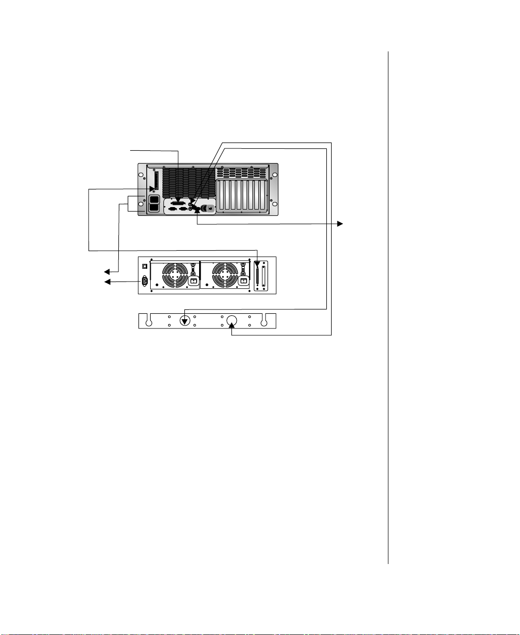
2. Verify that t he syste m drawer po w er switc h i s in the OFF position.
3. Connect controller and data cables to their respecti ve de vices as
appropriate (for example, SCSI cab les to a storage draw er , or parallel
cables to a printer , etc.) See the illustration Connecti ng Periphera ls
below.
Mouse
To printer
Keyboard
T o power
source
CPU drawer
SCSI channel
115V
T ape storage drawer
Keyboard and mouse tray
115V
Keyboard
Mouse
To VGA
monitoror
autoswitcher
9250R_08
Connecting Peripher als
4. Connect the keyboard , mouse, and video cab les to their respectiv e
ports. Systems with multipl e CPU dr a wers may require connecting
these cables to an autoswitcher unit. Refer to your rack system user’s
guide or “Connecting to an AutoSwitcher” on page 14 for the proper
connections.
5. Connect the monitor pow er cable to an appropriate po w er source.
6. Verify that t he v oltage sel ector swit ches on the power s upplies are set
for the proper volta ge ( 115V or 23 0V).
7. Connect the system pow er cables to the po wer input connec tors
8. Connect the other end of the system power cab les to the appropriate
pow er so urces.
Chapter 1: Getting Started 13
Page 28
Note:
Becausethe keyboard,
mouse,andmonitorare
plugged into the
AutoSwitcher, connecting
the system drawers to an
AutoSwitcher requires
extender cables.
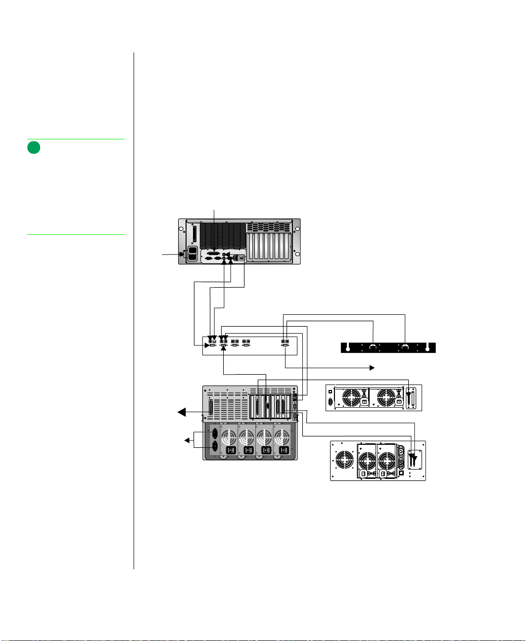
Using an autoswitcher
Multiple system dra wers installed i n the s ame syste m cabinet c an sha re a
single set of peripheral de vices ( monitor , k eyboa rd, and mouse) through the
use of an AutoSwitcher.
The AutoSwitcher provi des exclusiv e control of the monitor and routes the
keyboard an d mouse inputs to t he currentl y se lected s ystem dra wer .
Installing the AutoSwitcher is described in the Rack-Mountable System
User’s Guide. See the illustration Connecting to an AutoSwitcher below for
example connections.
To printer
To
power
source
Video
CPU drawer
Mouse
To
printer
To power
source
Keyboard
Mouse
4/8 autoswitcher
Video
CPU drawer #2
Connecting to an AutoSwitcher
Keyboard
Keyboard
Keyboardandmousetr ay
SCSI channel
AutoDAT backup drawer
SCSI channel 2
Storage drawer
SCSI channel 1
Mouse
To m onito r
115V
115V
115V
115V
9250R_09
14 Gateway ALR 9250R User’s Guide
Page 29

Po wering up the system
Lift the plastic cover o ver the po w e r s witch on the front pa nel a nd press i t,
and the green LED immediate l y beside t he po w er switc h t urns on.
If you turn off the server, you must w ait at le ast t en seconds before you t urn
it back on.
The system self-checks the memory even if the monitor is not connected. If
the monitor is connected and pow ered on, the screen displa ys the pow er-up
sequence.
• If more than one CPU is installed, the system displa ys which CPU
it is currentl y testi ng.
• If any e rrors are encounte red, the server displ a ys t hem on the
monitor .
• If a monitor is not connected or the syste m is unab le to display an
error, it sounds a n error beep code.
Warning!
!
Thetopcover mustbe
closed and secured while
thesystem is running.
• If the system e ncounters an erro r , it i s usuall y a nonfatal error,
meaning the system continues to function until the error is
corrected (usually through the BIOS Setup). In the rare case of a
fatal error, contact Ga te w a y for field service support.
Lookingthi ngsov er
Sometimes the simplest things can cause trouble. Before po w ering up the
system, perform the foll o wing checks:
• Are the po wer cords connected to the CPU syste m drawer and an
appropriate po wer source?
• Is the pow er source supplying po w er?
• If a po wer strip is used, is it s witc hed on? I s the circuit breake r se t?
• Does the v oltage sel ection switc h on the syst em’s pow er supply
reflect the proper v oltage ?
Note:
Under no circumstances
return any equipment
without obtaining a Return
Material Authorization
(RMA) number.
Chapter 1: Getting Started 15
Page 30

Warning!
!
Donotattempttoopenthe
monitor, it contains
components thatare
extremely dangerous. Even
if themonitor’s poweris
disconnected,stored
energy within the monitor’s
components can causean
electric shock.
V erifying your configuration
If the server i s not operating correctly, the BIOS may conta in an in v al id
configuration parameter. Enter the BIOS Setup pr o gram or the SSU and
check the configuration settings.
Troub leshootingguideli nes
As you troubleshoot y our system, keep the follo wing guidelines in mind:
• Never remo ve the syst em cover s while the system is pow ered up.
• If a periphera l such as the ke yboard, mouse, dri v e, or pri nter does
not work, ensure that all connections are secure.
• If an error message displays on the screen, write it down, w ord-for -
word. You may be asked a bout it whe n cal ling Technical Support.
• Only qualified personnel should open the syste m for maint enance.
• If you are qualified to maintain the system, make certain you are
properly grounded be fore opening the system’s chassis.
Completingth e installation
Once the cables are connected , you can use the system. Ho we ver , there are
some further procedures that help to ensure a clean installation and a
superior w orking e n vir onment for future maintenance acti vite s.
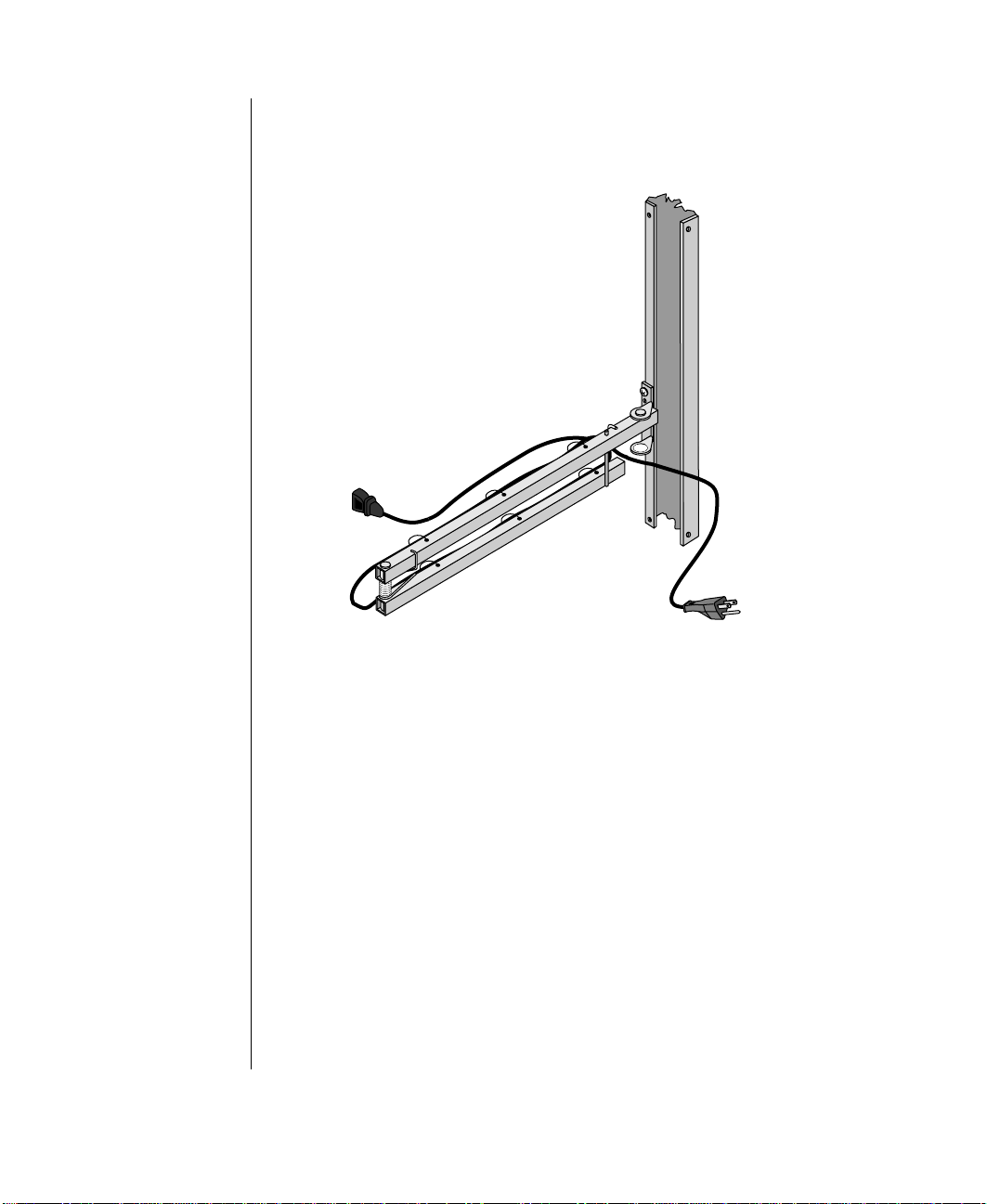
Installinga cable retractor
Cable retr actors of f er setup adv antages i n tha t the y reduce str ain on the
draw er cable s and connectors as well as simplifying maintenance because
they keep t he cab le s neatl y out of the way .
1. Position the c able retr actor to the r ear s ide of the c abinet so tha t the
16 Gateway ALR 9250R User’s Guide
To install a cable retractor
mounting holes on both retr actor a nd cabinet are a ligned.
Page 31

2. Using tw o screws, secure the cable re tractor to the mounting h oles on
the rear of the system draw er . See the illustration Insta lling a Cable
Retractor below.
Cable Retractor
9250R_01
Installing a Cab le Retr actor
Dressing the cables
Placing the cables in the cable retrac tor and ensuring that none are pinched
or streched is the final step in the installation process.
T o dress the system cables
1. Route the cabl e(s) from t he rea r of the system dr a wer ove r to the c abl e
retractor , w here i t i s mou nted on t he rea r of the drawer .
Chapter 1: Getting Started 17
Page 32
2. Secure the cables to the cable retract or with tie wraps. The cable
retractor is designed with tie holes for tie wraps. See the illustration
Routing Cable on the Cable Retractor belo w.
9250R_02
To powersource
3. Leav e enough slack in the cables to let them flex when the dra wer is
4. Check the cab les f or ti ght spot s while the dra w e r is being p ulled
5. Route the cables to their destinations and secure with tie wraps as
6. If necessary, bundle and secur e exc ess c able wi th a tie wrap to keep it
18 Gateway ALR 9250R User’s Guide
Routing Cable on the Ca b le Re tr ac tor
pulled out.
forward and pushe d back into place. Check for str ess points, especia lly
at the bends in the cable retractor and where the cable retr actor is
mounted to the vertical mounting rail.
required.
out of the way.
Page 33

Securing the system
Because of the nature of the rack system, primary physical security is
provide d b y the cabinet it self. The sec urity procedur es spe cified below are
in addition to any site security required.
T o secure the system
1. Close the rear doo r of the sys tem cabi net and lock i t if desired.
2. Push the system draw er back until its front panel presses against the
vertical mounting rails in the cabinet. Secure the draw er with four
screws.
3. Close the front door and lock it if desi red.
Chapter 1: Getting Started 19
Page 34

20 Gateway ALR 9250R User’s Guide
Page 35

Chapter 2:
System F eatures
Basic architec ture........ .... .... ....... .... ...... .... ..... ...... ..22
Front panel.......... .. ... .... .. .. .... .. .. ..... .. .. .... .. .. ..... .. .. ....23
Dual redundant 400- Watt power supplies.....23
Switches............ .... .. .. .. .. .. ..... .. .. .. .. .... .. ... .. .. .... ..24
3.5-inch diskette drive............. .... ...... ..... ...... ..24
CD-ROM drive... .. .... .. .. .... ... .... .. .. .... .. ... .... .. .. ..24
Storage bays...... .. .. .... .. .. .... ... .. .... .. .. .... ... .. .... .. ..24
LED indicators...... .... ...... ....... .... ...... ..... ...... ....25
Rear panel... .... .... ....... .... .... ...... ..... .... .... ....... .... .... ..26
Power connector s..... .. .... .. ... .... .. .. .... .. ... .... .. .. ..26
I/O ports......... ... .... .. .. .. .... .. ... .. .... .. .. .... ... .. .. .... ..27
Expansion slot cover plates......... .... ....... .... ....27
System board.... .. ..... .. .. .... .. .. .... ... .. .... .. .. .... ... .. .... .. ..28
Drive controlle rs a nd connector s............. .. ....29
System jumpe rs.... .. .... .. .... ... .. .... .. .. .... ... .. .... .. ..31
Miscellaneous c onnectors............. .. ..... .. .... .. ..32
Expansion slot connectors..... ...... .... ....... .... ....33
Memory module connector......... ......... .... ......34
System management c onnectors. .. .... ... .... .. .. ..34
Back panel I/O connect ors............ .... ... .... .. ....36
Processors and r elat ed connectors............. ....38
Power connector s..... .. .... .. ... .... .. .. .... .. ... .... .. .. ..40
Operating systems..... .... ...... .... ....... .... .... ....... .... ....41
Page 36

Basic arc hitecture
The system dra wer includes the following features:
• Support for up to four Intel P en tium
Xeon processors with dual 16 KB L1 cache integrated with an
additional 512 KB, 1 MB , or 2 MB of L2 cache
®
II Xeon or Pentium® III
• SMP design supporting up to four processor modules. Intel MP
Specification V1.1 and 1.4 compliant
• 32-bit PCI and ISA bus master; 64-bit data path processor and
memory data path; extended PCI-to-PCI bridge support
• 256-MB extended data out put (EDO), S DRAM memory,
expandable to 4-GB , using PC100 (100MHz) non- re gistered, 3.3V
DIMM memory modules in the singl e plug-in m odule with 16
DIMM sockets
• Integrated 32-bit DRAM PCI Graphics with 2-MB DRAM
• Seven P CI e xpansion slot s ( one shar ed)
• One ISA expansion slot (shared)
• Two embedded small computer systems interface (SCSI)
controllers:
• Symbios SYM53C810AE—narrow SCSI controller providing
support for legacy 8-bit SCSI devic es
• Symbios SYM53C896—dual-channel wide lo w volta ge dif ferential
(LVD)/single-ended (SE) (ult ra2/ult ra) SCSI cont roller dri ving one
SCSI backplane in the system and providing support for external
expansion
The system board is the main interface betw een the processor , memory, and
peripherals.
22 Gateway ALR 9250R User’s Guide
• RAC-400 ( 110V or 220V A C) P o wer Supply Subs ystem with dua l
redundant, hot s w appabl e 400 Watt po w er suppl ies
• Intel upgradable Flash BIOS, year 2000 ready
• N+1 cooling for syst em r eliability
Page 37

Front panel
The front panel pr o vide s controls to support system m aintenance and
provide s access to r emo v ab le media dri v es. See the il lustrat ion F ront P anel
below for the locations of the front panel features.
B
A
L
CD
EFGHI
J
K
Fr ont Panel
A Power supply on/off switches G System reset switch
B Power supply vo lt a geselection swit ches H Powersupp lyf ault reset switch
C 5.25-inch drive bay I Power supply fault LED
D 3.5-inch slimline diskette drive J Drawer on/off switch
E Slimline CD-ROM drive K Drawer power-on LED
F Hard drive activity LED L 400 W power supply modules
Dualredund ant 4 00-Wattpo wer supplies
9250r_4
Po wer is supplied to the CPU s ystem dra wer by an RA C-400 power suppl y
subsystem. This subsystem receiv es its pow er from two , hot swappa ble,
400-W att po we r supplies which are remo vab le from the front of the system
draw er . If one po we r supply should fail or become inoperativ e, it may be
changed out without shutting down the system. The system will continue
receiving po w er from the remaining pow er supply w hile the exchange is
taking place.
A voltage selection switc h is located on the upper front of each power
supply. These switches must be set for the appropriate input po wer (either
110V or 220V).
Chapter 2: System Features 23
Page 38

Switches
The system supports three s witches. The se s witches are de scribed belo w.
• Power-on: toggles the system on or off
• System Reset: allo ws you to reset the system without having to
pow er i t of f and t hen on a gain.
• Po wer Supply Fault Reset: cancels a power supply fault alarm
and clears the fault status
Additionally, the powe r supply modules each support tw o s witches, one to
turn the po we r on and off and the other to select the i ncoming li ne v oltage.
3.5-inchdiskettedriv e
The standard system is equipped with one slimline 1.44-MB 3.5-inch
diskette dri v e. Thi s dri v e is bracke ted with the sl imli ne CD-R OM dri v e a s
shown in the illustration F ront Panel on page 23.
CD-ROMdrive
The standard system is equipped with one slimline CD-ROM driv e. This
drive is br ackete d with the 3.5- inch slim line dis kette dri v e as shown in the
illustration the illustration F ront Panel on page 23.
Storage bays
The system can support up to six devices in the following bays :
24 Gateway ALR 9250R User’s Guide
• One 3.5-inch internal device: one internal mounting bracket is
provide d for the installation of a fixed media device.
• Three 5.25-inch f ront acce ssib le bays that support 5.25-inch
devices or 3.5-inch de vices with special mounting bracket.
Page 39

• One front accessible slim-line 1.44-MB 3.5-Inch disk ette driv e and
one front accessib le slim-line CD-ROM drive are b racket ed
together a nd i nstalled a bo ve the 5.25-inc h dri v e bays.
• Optional RAID cage, that supports up to three 3.5-inch Single
Connector Attachment (SCA) driv es. The RAID cage occupies the
5.25-inch driv e bays when insta lled.
LEDindica tors
The front panel su pports three LED indica tors to provide information on
system status. The se LEDs and thei r functi ons are described below:
• Power-on LED: The system is on
• Power Supply F aul t LED: One po wer supply module ha s
experienced a f ault condition
• Hard Drive Activit y LED: One or more of the ha rd dri v es is
being accessed
Chapter 2: System Features 25
Page 40

Rear panel
The rear panel of the system is equipped with I/O Ports and connectors. See
the illustration Rear Panel belo w for the locations of the rear panel
connectors.
A
D
B
C
F
E
H
G
J
I
K
9250r_5
Rear Pane l
A Power connectors G Video port
B USB port H Parallel port
C Mouse port I PCI slot A1
D Keyboard port J Intelligent chassis management bus (ICMB
E Serial port 2 K PCI slots A2, A3, B1, B2, B3, and B4 (B4 is
F Serial port 1
connector slot
shared with the ISA slot)
P owerconnec tors
These connect to a po wer source and provide pow er to t he power supplies,
via the po w e r supply subsystem, which distr ibutes power to the system and
its peripherals. Using the po wer cables supplied with the system, connect
each of the power supplies into a separa te w all o utle t or pl ug st rip.
26 Gateway ALR 9250R User’s Guide
Page 41

I/Oports
The system supports the sta ndard I/O ports a s described in the table
Back Panel I/O Ports below below.
Back Panel I/O Ports
Port Definition
Serial Ports 1
and 2
Par allel Port Parallel devices such as parallelprinters and scanners
Mouse Port This port supports any mouse with a miniature circular
Keyboard Port This port supports any keyboard with a miniature circular
Video Port Connects your monitor to the integrated video controller
USB Port Providesconnection point for USB-compliant peripheral
These are high speed serial ports which use the First-InFirst-Out(FIFO) protocol. If you havea serial mouse, connect it to Serial Port 1 (COM1). Other serial devices such
as serial printersormodems can also be connected these
ports.
can be connected to this port.
DIN (mini-DIN) connector.
DIN (mini-DIN) connector.
devices, such as modems, keyboards,joyst icks, etc.
Expansion slot cov er plates
These are temporary co ver plate s for their corresponding expa nsion slots on
the system board: s ix PCI sl ots and one shared P CI/ISA slot.
Note:
If your mouse has a miniDINconnector,you must
connect it to the Mouse
Port.
Chapter 2: System Features 27
Page 42

Syste mboar d
The system board is the main interface betw een the processor , memory, and
peripherals. See the illustration Sys tem Board below for the locations of the
major board features.
C DA E FB
G
LL
KK
JJ
II
HH
GG
FF
EE
DD
CC
BB
AA
P
Z
Y
X
W
V
Q
R
S
T
U
System Board
A Wide SCSI B connector J ICMB connector
B System jumpers K PCI slot A1
C Hard drive input LED connector L Video and parallel port connectors
D System speaker connector M Serial port connectors
E Lithium battery N Keyboard and mouse connectors
F Wake-on-LAN technology connector O USB external connector
G ISA slot P VRM connector for processor 4
H PCI slots B4 (top), B3, B2, B1, A3, and A2 Q VRM connector for processors 4 & 3
I Memory module connector R VRM connector for processor 3
H
I
9250R_14
J
K
L
M
N
O
28 Gateway ALR 9250R User’s Guide
Page 43

S VRM connector for processor 2 CC IDE connector
T VRM connector for processors 1 & 2 DD Diskette drive connector
U VRM connector for processor 1 EE Auxiliary power connector
V Processor 1 Slot 2 connector FF USB internal connector
W Main power connector, primary GG SMBus connector
X Processor 2 Slot 2 connector HH F16 expansion connector
Y Processor 3 Slot 2 connector II Narrow SCSI connector
Z Main power connector, secondary JJ External IPMB connector
AA Front panel connector KK SMM connector
BB Processor 4 Slot 2 connector LL Wide SCSI A connector
Drivecontro llersandconn ectors
The system board supports se ver al control lers and connector s for the
control of the va rious dr iv e s that are or can be i nstalled in the system.
SCSI connectors
The system board inc ludes t w o SCSI c ontrolle rs. A narrow SCSI contr oller
(SYM53C810AE) is on the PCI-A bus, and a dual-channel wide L VD/SE
(Ultra2/Ultra) SCSI control ler (SYM53C896) i s on the P CI-B bus. The
narrow controller pro vides support for legacy 8-bi t SCSI devices that may
be installed in the 5.25-inch drive bays. The wide controller dri ves one
SCSI backplane and pr o vide s sup port for exte rnal expa nsion.
Each controller has its own set of PCI configuration registers and SCSI I/O
registers. As a PCI 2.1 bus master, the wide controller supports burst data
transfers on PCI up to the maximum rate of 132 MB/sec using on-chip
buffers.
No logic, termination, or r esistor loa ds are requi red t o connect devi ces t o
the SCSI controller other than termination in the device at the end of the
cable. The SCSI bus is terminated on the system board with active
terminators that can be disabled.
Wide SCSI A and Wide SCSI B connectors
Internally, each wide channel is identical, capable of operations using either
8- or 16-bit SCSI providing 10 MB/sec (F ast-10) or 20 MB/sec (F ast-20)
throughput, or 20 MB /sec ( Ultra) or 40 MB/sec (Ultra-wide).
Chapter 2: System Features 29
Page 44

The wide controller contains a high-performance SCSI bus interface. It
supports SE mode with 8-bit (10 or 20 MB/sec) or 16-bit (20 or 40 MB/sec)
transfers and LVD mode with 8-bit (40 MB/sec) or 16-bit (80 MB/sec)
transfers.
Narro w SCSI c onn ect or
The narrow contr oller cont ains a high-performance SCSI core c apable of
Fa st 8- bit SCSI trans fers in single-ended m ode. It pr o vides pro grammable
activ e ne gation, PCI ze ro w ait-s tate bursts of f aster tha n 110 MB/se c at 33
MHz, and SCSI transfer rates from 5 to 10 MB/sec.
IDEconnector
This is an integrated Ultra-DMA PCI/IDE interface with an IDE connector
capable of c ontrolli ng up to tw o IDE devices. Ultra-DMA pro vides faster
access to IDE de vic es tha t are Ultra-DMA compl iant w hile m aintaini ng
support for IDE devices that do not support the Ultra-DMA specification.
Note:
You can connect an IDE
signal cable, up to a
maximumof 18 inches ,to
theIDEco nn ect o ron the
system board. The cable
cansup porttwodevices ,
one at the end of the cable
andonesixinchesfromthe
end.
The IDE controller supports:
• PIO and IDE DMA/bus master operations
• Mode 4 timings
• Transfer rate s up to 33 MB/sec
• Buffering for PCI/IDE burst transfers
• Master/slav e I DE mode
• Up to two driv es for one IDE channel
The IDE connector is connected to the auxiliary board on the back of the
cobracketted slim-line diske tte/CD-R OM drives via a 40-wire ribbon cable.
Diskettedriveconnector
The diskette dri ve c ontroller and connector on the system board can su pport
up to two diskette dri ves of 1.44-MB and 2.88-MB formats. This connector
is connected to the auxiliary board on the back of the cobra cketted slim-line
diskette/CD-R OM drive s via a 34-wire ribbon cable.
30 Gateway ALR 9250R User’s Guide
Page 45

System jumpers
These jumpers allo w y ou to set c ertain characte ristic s of t he syste m. Do not
change any jumper unless it is necessary to configure the system.
There may be additional jumpers on the system board. These jumpers are
reserved and should not be changed. In some cases, changing the s ettings of
reserved jumpers can cause damage to the syst em board.
ClearCMOSjumper
This jumper allo ws y ou to clear the compl imentary metal-o xide
semiconductor (CMOS) memory. You should only do this if you cannot
access the normal methods of modi fying the C MOS and modi fications to
the CMOS are necessary . Clearing CMOS memory returns all BIOS Setup
settings to the default v alues. This jumper oc cupies pins 1- 3 of t he
connector . S ee “C MOS Clear jumper” on page176 for more information
on setting the CMOS clear jumper.
Pass word clear jumper
Setting this j umper al lo ws y ou to cle ar the pass w ords. The de fault jumper
position protects the passwords. Use this jumper only if you have forgotten
the passw ords and cannot access the system. This jumper occupies pins 5-7
of the connector. See “Pa ss wor d Clear jumper” on page177 for more
information on using the password clear jumper.
Recoveryboot jumper
The recov ery boot jumper should be used only in the event of a failed BIOS
update. If you attempt a BIOS update and the update fails, set this jumper
and reboot the system. The syst em attempts to recover the pre vious ve rsion
of the BIOS as it boots up. This jumper occupies pins 9- 11 of the connector .
See “Reco ve ry Boot jumper” on pa ge 178 for more information on setti ng
the reco very boot jumper.
Chapter 2: System Features 31
Page 46

Miscella neousconn ectors
The system board supports a v ari ety of c onnectors f or man y functions.
Many of these connectors are described in this section.
Hard driveinput LED connector
This connector allows you to con nect a cab le f rom an add- in har d disk
controller to the system board to allow the add-in controlle r to activa te the
hard drive acti vity LED on the control panel.
System speaker connector
Connects the internal speaker to the system board. This connector is not
used in this c onfiguration.
Wak e-on-LAN technologyconnector
The wake on local area network (LAN) technolog y c onnector allo ws y ou t o
connect a magic packet-enabled LAN adapter to the system board to
support wake on LAN functionality. W ake on LAN functionality allo ws a
system in power conservation mode to be awakened b y an inc oming
message on the network.
F ront panelconnector
The front panel c onnector pro vi des the signals for the fr ont cover indicator
LEDs and the fron t cover buttons.These signa ls pas s through an auxi liary
board installed on the right side of the chassis connected to the system
board through a 30-wire ribbon cable. The auxiliary board supports an
alarm buzzer and connects to the power- on switch and LED and a small
LED/switch board that supports the hard drive acti vity LED , the po w er
supply fault LED , the system reset swit ch, and the pow er supply fault reset
switch.
32 Gateway ALR 9250R User’s Guide
Page 47

USB internal connector
This connector allows you to co nnect i nternal devi ces t hat use the US B
interface to the US B cont roller on the sys tem boar d. This connector is not
used in this c onfiguration.
Lithium battery socket
Holds the battery that provides pow er to maintain the CMOS memory when
the system is turned of f or unplugged.
Expansions lot connectors
The system supports seve n expansion car ds. One slot is sha red and supports
either a PCI card or an ISA card.
ISAslot
The system board ha s one i ndustry standar d architec ture (ISA) slot t hat is
full-length if you do not use the wide SCSI-B connector (a nd half-l ength if
you use the wide SCSI-B connector). The ISA slot supports slave-onl y
boards and is shared with PCI-B slot 4. The ISA bus also supports three
embedded devices: the Super I/O chip, system board management
controller (BMC), a nd flash memory for the sys tem B IOS. ISA bus
features:
• Bus speed up to 8. 33 MHz
• 16-bit memory addressing
• Type A transfers at 5.33 MB/sec
• Type B transfers at 8 MB/sec
• 8- or 16-bit da ta tra nsfers
• Plug and Pla y r eady
Chapter 2: System Features 33
Page 48

PCIslots B4(top), B 3, B2, B1,A3, A 2, A1
The system board ha s tw o 32-bit pe riphe ral component interconne ct (PCI)
bus segments: PCI-A and PCI-B. These pro vide seve n slots for PCI
expansion cards: three on PCI-A and four on PCI-B. PCI-B4 is shared with
the ISA slot. PCI-A1 supports half-length boards only. The other slots
support full-length boards. PCI bus features:
• 33 MHz bus speed
• 32-bit memory addressing
• 5 V signaling e n vironment
• Burst transfers of up to 133 M B/sec
• 8-, 16-, or 32-bit data transfers
• Plug and Play ready
• Parity enabled
Memory moduleconnec tor
The memory module connector supports the memory module. The
memory module is a proprie tary card that supports all of the mai n memory
for the system. The memory module is describe d in “Operating sys tems”
on page 41.
Systemmana gement connectors
Server Management feature s are implemented using one mi crocontrol ler ,
the system board m anagement contr oller (BMC).
The BMC and associated circuitry are powered from the 5 V standby line,
which remains a cti v e w hen the system power is switc hed of f .
The primary function of the BMC is to autonomously monitor system
management events and log the ir occurrence in the nonvolat ile system
event lo g (SEL). These event s include o vertemperature and o vervoltage
conditions, fan failure, or chassis intrusion. While monitoring, the BMC
maintains the nonv olatile sensor data record reposit ory (SDRR), from
whic h ru n- ti m e i nf ormat i on can be r etr ieved. The BMC pr ovides an ISA
34 Gateway ALR 9250R User’s Guide
Page 49

host interface to SDRR inf ormation, so softw a re running on the server can
poll and retri ev e the current stat us of t he hardw a re. A sha red registe r
interface is defined for this purpose.
SEL contents can be retri ev ed a fter s ystem failure for anal ysis b y field
service personnel using system management tools like Intel
Server Manager . Because the BMC is pow ered b y 5V_Standby, SEL (and
SDRR) information is also available via the int erperipheral management
bus (IPMB). An emergency management board like the Intel LANDesk
server management module (SMM) board can obtain the SEL and make it
remotely accessib le using a LAN or telephone line connection.
During monitoring, the BMC performs the following functions:
®
LANDesk®
• System board temperature and v ol tage monitoring
• Processor presence monitoring and fault resilient boot (FRB)
control
• System board fan failure detection and indicator control
• SEL interface management
• SDRR int erfac e man ageme nt
• SDR/S EL tim estamp clo ck
• System board field replaceable unit (FR U) information interface
• System management wa tchdo g t imer
• Periodic system management interrupt (SMI) timer
• Front panel non-maskab le interrupt (NMI) handling
• Event receiver
• ISA host and IPMB interface management
• Secure mode control, front panel lock/unlock initiation, and video
blank and diskette write protect monitoring and control
• Sensor ev ent i nitializ ation a gent
• W ak e-on-LAN via Magic Pa cke t support
• ACPI Support
• Emergency Management P ort (EMP) support
Chapter 2: System Features 35
Page 50

ICMB connector
The intelligent c hassis m anagement bus (ICMB) connector a llo ws the
connection of a sy stem management component t o monitor the c hassis
characteristics including temperat ure, voltages, intrusion detection, and fan
speeds.
SMBus c onnector
This connector suppo rts an SMBus card t hat provides system management
functions.
F16 expansion connector
The F16 expansi on connector allows you to connect a component to the
F16 bus which communicates between the memory and I/O controller
(MIOC) and the PCI expansion bridge (PXB).
External IPMBconnector
This connector allows y ou to connect an “external” device to the IPMB to
help determine the cause of a s yste m failure fr om a remote terminal.
SMM connector
The SMM connector allows you to connect a sys tem management module
to the system board to monitor the system and perform other system
management functions.
Backpanel I/O connectors
The back panel supports the standa rd a rray of I /O connectors. These
connectors are de scribed i n the pa ragraphs below .
36 Gateway ALR 9250R User’s Guide
Page 51

Video port connector
The onboard, integrated Cirrus Logic CL-GD5480 64-bit VGA chip
contains an SV GA controller that is fully compatib le with the V GA video
standard. The system board pr o vide s 2 MB of 10 ns onboard video
memory . The video controller supports pixel resolutions of up to
1600 x 1200 and up to 16.7 M colors. You cannot add video memory to this
system.
The SV GA controll er sup ports anal og VGA monitors (single and multiple
frequency, interlace d and noni nterlac ed) with a maximum v ertical r etrace
noninterlaced frequency of 100 Hz. Depending on the env ironment, the
controller displa ys up to 16.7 M colors in some video resolutions.
Compatible video dri vers are pro vided with the operating system or the
utilities.
Paral lel port connector
The 25/15-pin connector stacks the paral lel port beside the VGA video port.
BIOS programming of the super I/O chip registers enables the parallel port
and determines the port address and inte rrupt. The system BIOS pr o vide s
fields in the setup utility to easily enab le the parallel port and set the port
address and interrupt. When disabled , the interrupt is av ailab le to expansion
cards.
Serial port connectors
Both serial ports are relocata b le. By de fault, port 1 is the l eft connect or ,
port 2 on the right. Each serial port ca n be set to one of four dif ferent
COMx ports, and each can be enabled separately . The system BIOS
provide s fields in the setup utilit y to easil y e nabl e both s eria l ports and se t
the port addresses and interrupts. When disabled, serial port interrupts are
av ail able t o e xpansion cards.
Chapter 2: System Features 37
Page 52

Note:
A second USB port internal
to the system chassis is
provided at position FF as
shown in the illustration
System Board on page 28
Ke yboardand mouseconnectors
The PS/2-compatible ke yboard and mouse connectors are mounte d in a
single-stacked housi ng with the m ouse connector to the lef t of the
keyboard. External to the system, they appear as tw o connectors.
You can plug in the keyboard and mouse to either connector before
pow ering up the system. BIOS detects the device connected at each
connector and configures the keyb oard contr oller accordingl y.
The keyboard controller is functionall y compatib le with the 8042A
microcontroller . The system can be locked automaticall y if no keyboard or
mouse activity occurs for a predefined length of time, if specified through
the SSU . Once the inacti vity (lockout) timer has expired , the keyboard and
mouse do not res pond unti l the previously stored password is entered.
USB external connector
One universal seri al bus (USB) port provides connection for a growing list
of peripheral components including mouse, keyboard, joysti ck, monitor ,
tape and diske tte dri v es. Up to 127 de vic es can be da isy-chained f rom t he
port. The USB port also pro vides hot- sw ap capability and dynamic resource
allocation for all peripherals attached to it with data transfer rates of up to
12 Mbps. USB dri ve rs a re provided as a part of most m ajor operating
systems and should require no special procedures for implementation or
use.
Processorsandrelated connectors
The system board supports four slot 2 pr ocessor connectors and supports
and six associated VRM connectors. These connectors are described in the
paragraphs belo w.
VRM connectors
In this syste m each proce ssor must ha v e one VR M to a djust the v oltage
supplied to the processor core and one to adjust the voltage supplied to the
second-lev el cache in the SEC cartridge. The first VRM is dedicated to a
single processor and provide s the correct pow er to the processor core. The
second VRM provides po w er to the integrated second-lev el cache and can
38 Gateway ALR 9250R User’s Guide
Page 53

support the cache on two SEC cartridges. Therefore each processor requires
1.5 VRMs. See the tab le P rocessors a nd Ass ociated VRMs below for the
allow ed processor and VRM configurations.
Processors and Associated VRMs
Processor
Installed
Processor 1 VRM 1 Powers the processor core for processor 1
Processor 2 VRM 3 Powers the processor core for processor 2
Processor 3 VRM 4 Powers the processor core for processor 3
Processor 4 VRM 6 Powers the processor core for processor 4
VRM
Installed
VRM 2 Powers the second-level cache forprocessors 1 and 2
VRM 5 Powers the second-level cache forprocessors 3 and 4
VRM Function
Processorslots
Each Pentium® II Xeon™ or Pentium® III Xeon™ processor is packaged in
an SEC cartridge. The cartridge includes the processor core with an
inte grate d 16 KB primary ( L1) ca che; t he se cond ary (L2) cache ; a therma l
™
plate; and a back cove r . The processor implements MMX
maintains full backward compatibility with the 8086, 80286, Intel386
™
Intel486
, Pentium, P entium Pro, and Pe ntium II processors.
Each SEC cartridge connects to the system board through a Slot 2 edge
connector . The cartridge i s secured by a retention bra cket attached to the
system board. Depe nding on co nfiguration, the server has one to four
processors.
technolog y and
™
,
The processor external interface is multiprocessor (MP)-ready and operates
at 100 MHz. The processor contains a local advanced programmable
interrupt controller (APIC) for interrupt handling i n MP and u niprocessor
(UP) envir onments. The system SMP design supports up to four processors
and is Intel MP Specification v1.1 and 1.4 compliant.
The second-lev el c ache is locat ed inside the SEC cartrid ge. The c ache
includes burst pipelined synchronous static RAM (BSRAM) and is offered
in 512 KB, 1 MB, and 2 MB configurations, with ECC that operates at the
full core cloc k rate.
Chapter 2: System Features 39
Page 54

Each processor cartridge requires two VRMs to pro vide po wer to the
processor core and the second-leve l cache, respecti vel y . The full details of
the installation of processors and VRMs are provided in “VRM connectors”
on page 38.
P owerconnec tors
There are se v eral power connectors that provide pow er f or th e syste m
board. Some of these connec tors pr o vide po wer for specialized func tions.
Main power connector , primary
The primary power connectors provide the majority of t he po w er to the
system board. These connectors are de signed to accommodate the p ower
supply installed in the system.
Main power connector , secondary
The primary power connectors provide the majority of t he po w er to the
system board. These connectors are de signed to accommodate the p ower
supply installed in the system.
Auxiliary power connector
The auxiliary po w er connect or provides for the connecti on of a n addit ional
pow er so urce.
40 Gateway ALR 9250R User’s Guide
Page 55

Operating systems
The Gatew a y ALR 9250R is compliant with t he Int el MP S pecification
V1.1 or V1.4 (BIOS-se lectab le). The following operating systems support
symmetrical multiprocessing (SMP):
• Nov ell NetW ar e 4.1 and 5.0
• SCO UNIX Open Server 5.xx
• UnixWare 7.0.1
• Windo ws NT
• Windo ws NT
• Microsoft Backof fice Small Business Se rver 4.0 (SBS)
Current versions of the various operating systems are constantl y changing.
Contact Gatewa y Technical Support for the latest information about
operating systems a nd supported versions.
If your ope rating syst em doe s not support multiproce ssing, the serv er
adjusts the oper ating mode to asymmet rical, meaning onl y the first
processor accepts I/O interrupts. Any additiona l processors in the system
receiv e only interprocessor interrupts.
™
Server 4. 0
™
Server 4.0 Enterprise Edition
Important!
TheP entium® IIXeonand
Pentium III Xeon
proces s or sare designedto
support 32-bit operating
system sand applicati on s.
T o ensure optimum system
performance, use only 32bitpro grams on the system.
Chapter 2: System Features 41
Page 56

42 Gateway ALR 9250R User’s Guide
Page 57

Chapter 3:
Components
Introduction... .. .. .... ... .. .. .. .. .. .... .. ... .. .. .. .. .... .. ... .. .. .. .. ..44
Processors... .. .. .. .... ... .. .. .. .. .. .... .. ... .. .. .. .. .... .. ... .. .. .. .. ..44
Replacing th e proce ssor... ..... .. .. .... .. ..... .. .. .... ..44
Installing another proce ssor.... ...... .... ....... .... ..48
Installing a VRM............ ....... .... ...... ..... ...... ....52
Memory..... .... .... .... ....... .... .... .... ..... ...... .... ..... .... .... ..54
DIMM installation sequence....... ...... ..... ...... ..55
System memory ad dressing........ .. .... ... .... .. .. ..55
Memory configurat ion..... ..... ...... .... ..... ...... ....56
Removing the memory modul e............... .. .. ..56
Removing DIMMs....... .... ... .. .... .. .. .... ... .. .... .. ..58
Installing DIMMs............. ....... .... ...... ..... ...... ..59
Installing the memory module.......... ..... ...... ..60
Expansion cards......... ...... .... .... ....... .... .... ....... .... ....62
Power Supply Modules......... ..... .. .. .... .. .. ..... .. .. .... ..64
Storage bays........ .. ... .... .. .. .... .. .. ..... .. .. .... .. .. ..... .. .. ....66
5.25-inch devi ce ......... ...... ..... .... ...... ..... .... ......67
3.5-inch devi ces........ .... ....... .... .... ...... ..... .... ....68
RAID cage (optional).............. .... ...... ..... ...... ..70
Page 58

Note:
If the server has less than
fourprocessorsandyou
are adding one, then you
must remove the
terminat ion boar dassembly
from the next Slot 2
connector befor eyou install
the new processor. If you
plan to reduce the number
of processors in your
system ,then you must
replace a processor with a
termination board
assembly.
Introduction
Your system has been configured for the Pentium II Xeon or Pentium III
Xeon processor . Ho we ver , the system can be enhanced with v arious options
to meet your future needs, s uch as installi ng up to t hree a dditional
processors. This c hapter c ontains proc edures th at as sist you in insta lling
some of these options.
Processors
Your system supports up to three additional processors to further enhance
system performance. CPU Upgrade kits, w hich provide all of the
components that y ou need t o ins tal l an additi onal processor, are readily
available from Gateway.
Replacin g theprocesso r
The system is c ompatible with Intel Pentium II Xeon and Pentium III Xeon
processors. You can either upgrade the existing Pentium II Xeon processor
or install up to thr ee more p rocessors of the same speed and cache size as
the first processor .
When replacing a processor , orde r a pr ocessor upgrade kit. The kit i ncludes
the upgrade processor, a heat sink, and latches.
It is critical that a heat sink be installed on each processor . The Pe ntium
family of processors ma y overheat and fail if not coole d suf ficiently. The
heat sink provided with the processor in t he syste m pro vi des all ne cessary
cooling for the processor .
For the latest details on the av ailability of the upgrade kits, contact one of
the sources li sted in the Assis tance Resourc es document shipped with the
serve r .
1. T urn off the system and disconnect all the po wer cords.
44 Gateway ALR 9250R User’s Guide
T o Replace the Processor
Page 59
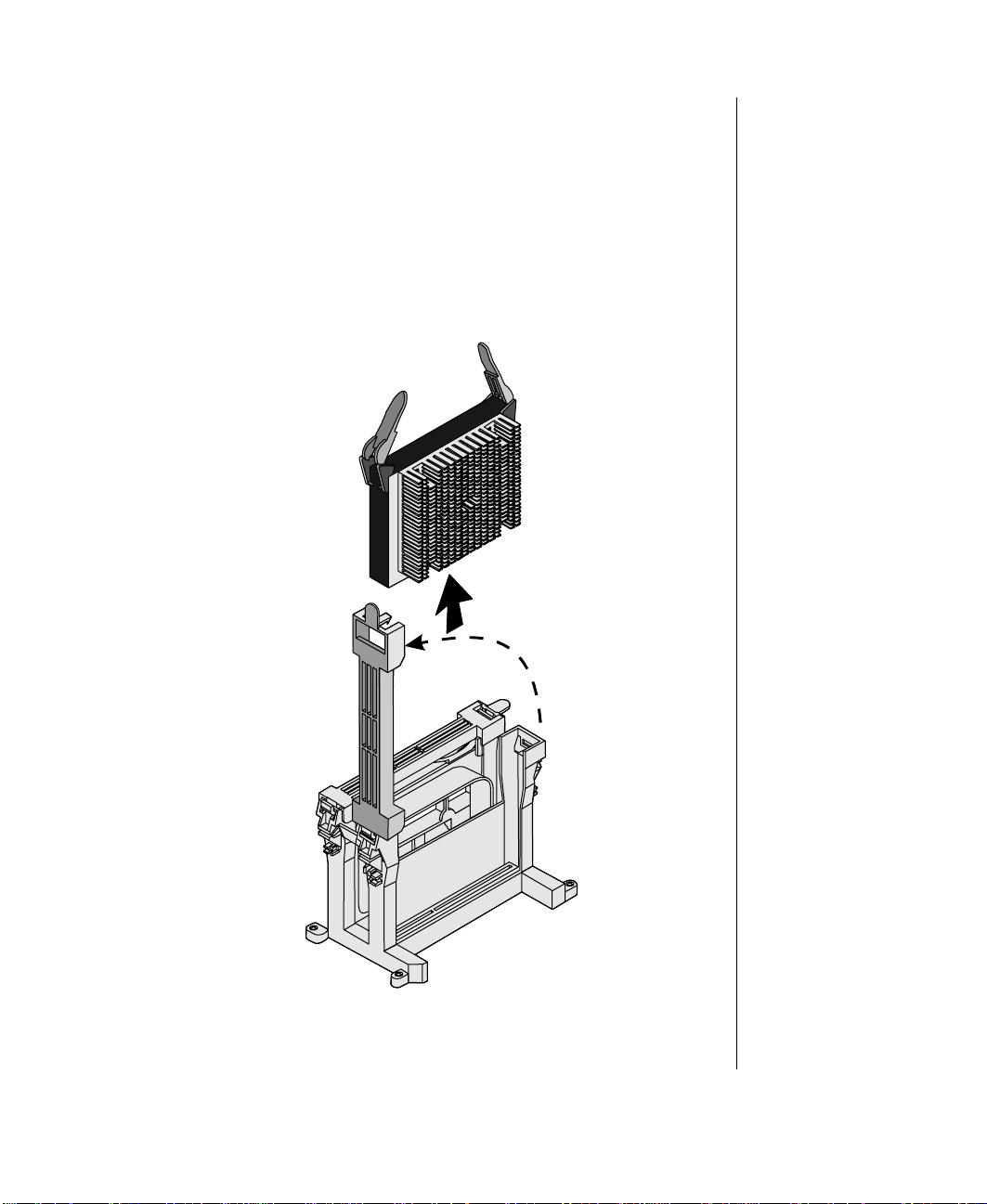
2. Open the case, o bserving the sta tic ele ctri city preca utions in “Stati c
electricity precautions” on page 2.
3. Wear an anti-static wristba nd grounded to the s ystem chassis and
place processors on a grounded , static-free surface or conducti ve foam
pad.
4. With y our thumb on the face of the retention module bracket, wrap
your index finger around the tab protruding from the right edge of the
bracket. See the illus tration Remo vi ng the Ol d P rocessor bel o w.
Removing the Old Processor
9250R_28a
Chapter 3: Components 45
Page 60

5. Use your index finger to slightly pull the tab outward and to the left.
Do not try to pull the entire bracket. The back of the tab has a latch
that releases when the tab is pulled slightl y .
6. When you hav e released the right edge of the bracket, lift it until it is
perpendicular to the front of the retention module.
7. Pull the two tabs attached to the single edge contact (SEC) cartridge
(visible after y ou r emo v e the bra cket) straight up. As y ou do, the
cartridge disengages from th e connect or on t he syste m board.
8. Slide the SEC cartridge straight aw ay from the system board , out of
the retention module. Put it on a piece of conductive foam and store it
in an antistatic package.
9. Remove the replacement processor cartridge from its protecti ve
wrapping.
10. Orient the SEC cartridge so that the heat sink faces awa y from the
center of the system board.
11. If you are inst alling a termination c ard asse mbl y, orient it so that the
side with the label faces tow ard the center of the system board.
46 Gateway ALR 9250R User’s Guide
Page 61

12. With the tabs at the top of the SEC cartridge completely open (pulled
outward , a w ay from the center of the cartridge) , slide the cartridge into
the guide rails of the retention module. The triangular ends of the tabs
fit into the entrance to the guide rails. See the illustration Installing a
New Processor below .
9250R_28b
Installing a New Pr oc essor
13. When the cartridge m eets resista nce, push the tw o tabs toward each
other until t he proce ssor is full y seated. See the illustr ation I nstalli ng a
New Processor above.
Chapter 3: Components 47
Page 62

Note:
If the server has less than
fourprocessorsandyou
are adding one, then you
must remove the
terminationboard assembly
from the next Slot 2
connector before you install
the new processor. If you
plan to reduce the number
of processors in your
system, then you must
replace a processor with a
termination board
assembly.
14. With the bracket in an open position (perpendicular to the front of the
retention module), rotate the bracket to the right until it reaches the
retention module. W ith your thumb on the face of the bracket and y our
index finger around the tab at the end of the brack et, pull the tab gentl y
outward and t o the left to open the latch a t t he back o f the tab.
As you open the latch on the back of the tab, slide the right edge of the
bracket onto the retention module and release the tab . The bracket
latches securel y.
15. Close the case, as d escribed in “Closing the system” on page 5.
16. Reconnect the power cord and turn on t he system.
Installi ng anotherprocess or
The system is c ompatible with Intel Pentium II Xeon and Pentium III Xeon
processors. You can either upgrade the e xisting pr ocessor or i nsta ll up to
three additional processors of the same speed as the original processor .
When adding a proce ssor , or der a processor upgrade kit. The ki t include s
the processor , a hea t si nk, and latches.
It is critical that a heat sink be installed on each processor . The Pe ntium
family of processors ma y overheat and fail if i t is not coo led suf ficiently.
The heat sink pr o vide d wit h the proc essor in the system provides all
necessary cooling for the processor.
For the latest details on the av ailability of the upgrade kits, contact one of
the sources li sted in the Assis tance Resourc es document shipped with the
serve r .
1. T urn off the system and disconnect the po wer cord.
2. Open the case, ob serving the sta tic ele ctricity precau tions in “Stati c
48 Gateway ALR 9250R User’s Guide
To Install a Second Processor
electricity precautions” on page 2.
Page 63

3. Wear an anti-static wristba nd grounded to the s ystem chassis and
place processors on a grounded , static-free surface or conducti ve foam
pad.
4. Remove the termination card in the lowe st numbered empty processor
slot. (Processor slots are numbered from the edge of the system board
tow ard the center of the board.) With y our thumb on the face of the
retention module bracket, wrap your index finger around the tab
protruding from the right edge of the bracket.
5. Use your index finger to slightly pull the tab outward and to the left.
You should not try to pull the entire bracket; rather , the back of the tab
has a latch that rel eases w hen the t ab is pulled sl ightl y.
6. When you hav e released the right edge of the bracket, rotate it until it
is perpendicular to the front of the retenti on module.
Chapter 3: Components 49
Page 64

7. Pull the two tabs attached to the termination module (visible after you
remov e the bracke t) st raight a w ay from the system board. As y ou do,
the termi nati on module dise ngages from the c onnector on the syste m
board. See the illustration Remo ving the T e rmination Module below.
8. Slide the termination module straight awa y from the system board , out
9. Remove t he processor cartrid ge from it s pr otecti ve wrapping.
50 Gateway ALR 9250R User’s Guide
9250R_29
Removing t he Termination Module
of the retention module. Put it on a pie ce of conducti ve foam a nd store
it in an antistatic package.
Page 65
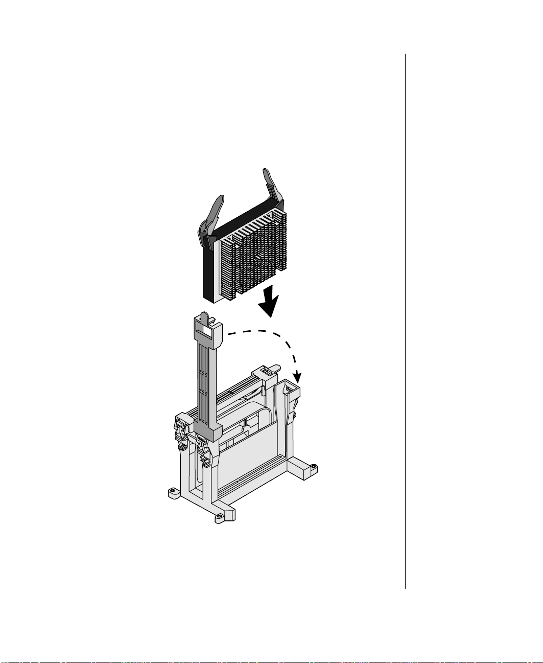
10. Orient the SEC. ca rtridge so that t he heat sink faces away f rom the
center of the system board.
11. With the tabs a t the top of the SEC. c artridge c ompletel y op en (pul led
outward , a w ay from the center of the cartridge) , slide the cartridge into
the guide rails of the retention module. The triangular ends of the tabs
fit into the entrance to the guide rails. See the illustration Installing a
Processor belo w .
Installing a Processor
9250R_28b
Chapter 3: Components 51
Page 66

12. When the cartridge m eets resista nce, push the tw o tabs toward each
other until t he proce ssor is full y seated. See the illustr ation I nstalli ng a
Processor abo ve.
13. With the bracket in an open position (perpendicular to the front of the
retention module), rotate the br acket do wn unti l i t reac hes the
retention module. W ith your thumb on the face of the bracket and y our
index finger around the tab at the r ight of th e brac ket, slight ly pul l t he
tab upward and to the left to open the latch at the back of the tab.
As you open the latch on the back of the tab, slide the right edge of the
bracket onto the retention module and release the tab . The bracket
latches securel y.
14. Close the case, as d escribed in “Closing the system” on page 5.
15. Reconnect the power cord and turn on t he system.
Installi ng a VRM
Each processor re quires two VRMs to control po wer to the process or core
and the integrated second-lev el cache respectiv ely. The VRMs for cache
pow er c an support the cache on two pr ocessors. For more information on
VRMs see the tab le P rocessors a nd Associate d VRMs, on page 39.
1. Open the system, as described in “Opening the system” on page 2, and
2. Remove the new VRM from its packaging.
Note:
BoththeVRMandthe
socket are keyed to prevent
improper connection.
52 Gateway ALR 9250R User’s Guide
3. Hold the ne w VRM o v er the VRM soc ket and v erify t hat the pins on
T o Install a VRM
locate the VRM socket on the system board.
both VRM and socket are aligned.
Page 67
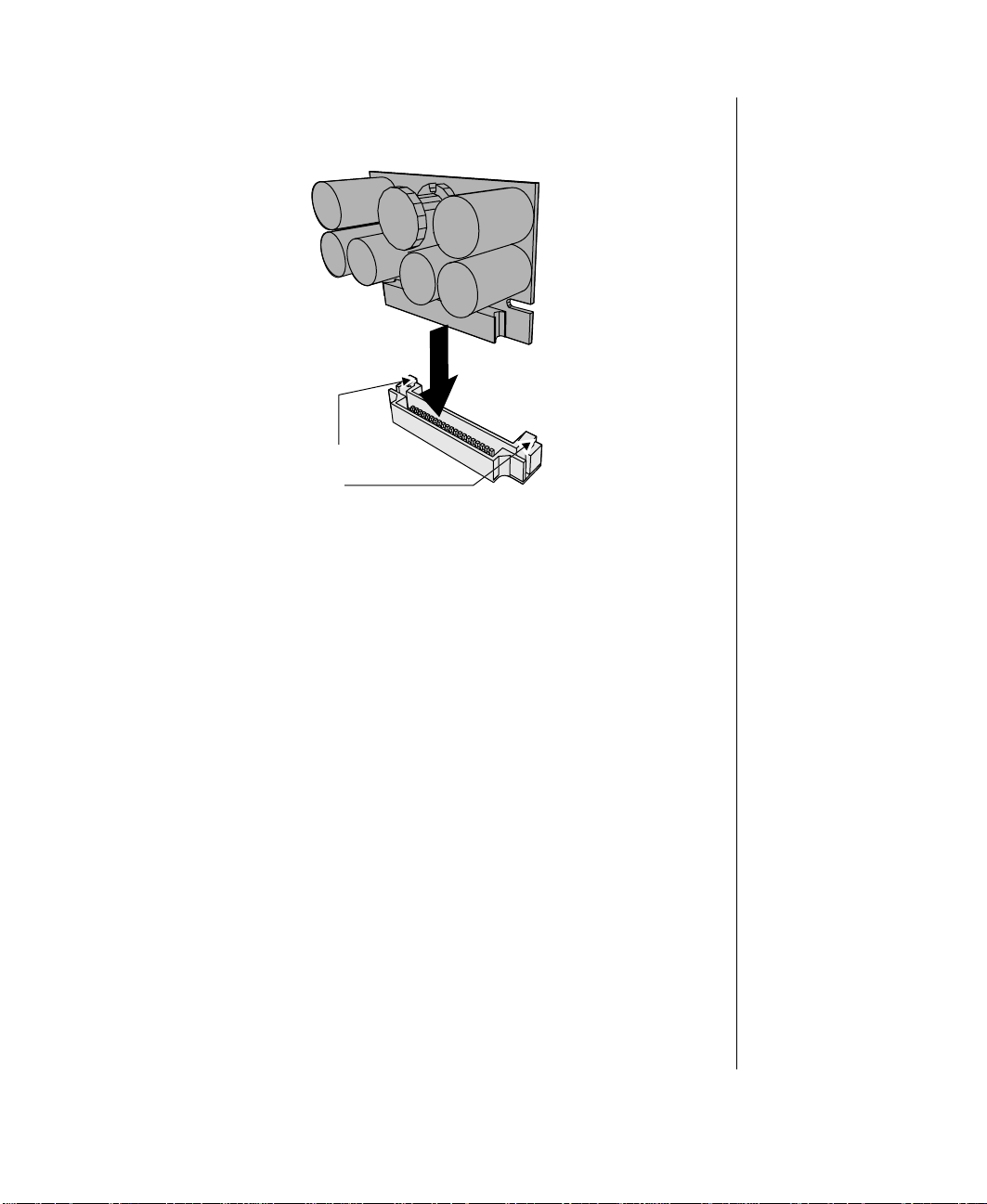
4. Gently insert the new VRM into the socket and push in until it latches
into place. See the illustration Installing a VRM below.
9250R_03
Quick release tabs
Installing a VRM
Chapter 3: Components 53
Page 68

Memory
The system comes standard with 256-MB of ECC RAM. System RAM is
expandable up to 4-GB using ECC 50- or 60-ns 72-bit EDO DIMMs
(16 DIMM sockets) with gold contacts.
Main memory resides on an expansion card, called a memory module,
designed specifically for thi s server. (See the il lustr ation Memory Banks
below.) The memory module contains slots for 16 DIMMs, each of w hic h
must be at least 32 MB, and is attached to the system board through a
dedicated connector . Memory amounts from 128 MB to 4 GB of RAM are
supported , with a 64/72-bit four-wa y-interlea ved pathway to main memory .
The 16 slots a re di vide d into f our ba nks of four s lots each, labele d A
through D . These ba nks s upport 4:1 inter lea ving. The memory controller
supports EDO DRAMs. The ECC used for the memory module is capable
of correcting single-bit errors (SBEs) and detecting 100 percent of doublebit errors o ver one code w or d. Nibb le error detection is also provided.
54 Gateway ALR 9250R User’s Guide
J16
J15
J12
J11
J8
J7
J4
J3
D
C
B
A
J14
J13
J10
J9
J6
J5
J2
J1
9250R_30
Memory Banks
Page 69

DIMMinst allationsequ ence
You must install DIMMs in the correct order and in entire banks. All
DIMMs in the bank must be the same size and speed. DIMMs in other
banks may dif fer in size. If you use slow er DIMMs in another bank, all
DIMMs operate at the slowe r speed (see the illustration Memory Banks on
page 54).
The sequence in w hich y ou must fill the banks is:
1. Memory ban k A
2. Memory ban k B
3. Memory ban k C
4. Memory ban k D
System memory addressing
System memory begins at a ddress 0 and is conti nuous (f lat addr essing) up
to the maximum amount of DRAM i nstalled ( excepti on: s ystem memory is
noncontiguous in the ranges defined as memory holes using configuration
registers). The system supports both base (conv entional) and extended
memory.
Note:
Eachmemorybank
includes two DIMM sockets
in each row of connectors.
When installing DIMMs, be
careful to install the DIMMs
in the correct sockets for
the bank.
• Base memory is located at addresses 00000h to 9FFFFh (the first
1 MB).
• Extended memory begins at address 0100000h (1 MB) and
extends to FFFFFFFFh (4 GB), w hich is the l imit of supported
addressable memory. The top of physical memory is a maximum
of 4 GB (to FFFFFFFFh)
Memory holes can be configured in Setup or the SSU and are used by some
legacy ISA boards. If you do not need to set up a memory hole for an ISA
expansion board , lea ve the memory in a contiguous state for optimal
performance.
Chapter 3: Components 55
Page 70

Note:
UseDIM Msthat havebeen
tested for compatibility with
thesystemboard. Contact
yoursalesrepresentative or
dealer for a list of approved
DIMMs. In the table
Memory Configuration
some sample size
combinationsarelisted.
Memory configuration
BIOS automaticall y d etects, sizes, a nd initializes the m emory array,
depending on the type, size, and speed of the installed DIMMs, and reports
memory size and allocation to the system via configuration registers.
In a 4 GB configuration, a small part of memory (typically 32 MB) is not
remapped abo ve 4 GB. If the OS doe s not su pport more tha n 4 GB of
physical memory, this small part of the memory is effecti vel y lost.
Memory Configuration
Bank A
(slotsJ1 - 4)
4x64 256 MB
4x64 4x32 384 MB
4x64 4x32 4x32 512 MB
4x64 4x64 512 MB
4x64 4x64 4x32 4x32 768 MB
4x64 4x64 4x64 4x64 1024 MB
4x128 4x64 4x32 4x32 1024 MB
4x128 4x128 4x64 4x64 1536MB
4x128 4x128 4x128 4x128 2048 MB
4x256 4x128 4x64 4x64 2048MB
4x256 4x256 4x128 4x128 3072 MB
4x256 4x256 4x256 4x256 4096 MB
Bank B
(slotsJ5 - 8)
Bank C
(slots J9 - 12)
Bank D
(slotsJ13 - 16)
Total
Memory
Removing the memory module
The memory module must be remov ed before you can change the memory
configuration. See “Operating systems” on page 41 for memory size and
requirements.
1. Observe the safety and ESD precautions in “Static electricity
2. Remove the access co ver (see “Opening the system” on page 2).
56 Gateway ALR 9250R User’s Guide
T o Remove the Memory Module
precautions” on pa ge 2.
Page 71

3. Remove t he memory module from the s ystem board b y pulli ng it
gently from the dra wer. See the illustration Remo ving the Memory
Module below.
9250R_35a
Removing the Memory Module
4. Place the module c omponent-side up on a nonconducti v e, stat ic-free
surfa ce .
Chapter 3: Components 57
Page 72

Removing DIMMs
When removing DIMMs, remember that DIMMs must be installed by
banks. Each bank consists of four DIMM sockets. All DIMMs in a bank
must be installe d and must be of the sa me si ze and s peed. See the
illustration Memory Banks on page 54 for the location of the DIMM
sockets in each bank.
To Remove DIMMs
1. Observe the safety and ESD precautions in “Static electricity
precautions” on pa ge 2.
2. Remove t he memory module and pla ce it component-side up on a
nonconductiv e, static-free surface (see “Remo ving the memory
module” on page 56).
Caution!
Useextreme care when
removing a DIMM. Too
muchpressure can
damagethe socket. Apply
onlyenough pressureon
theplastic ejector levers to
release the DIMM.
3. Gently push t he plastic e jector le ver s out and down to eject a DIMM
from i t s s o ck et.
4. Hold the DIMM onl y b y i ts ed ges, be ing careful not t o touch its
components or gold edge connectors. Carefully lif t it aw ay f rom the
socket and store it in an antistatic package.
5. Repeat Steps 3 and 4 to remove other DIMMs as necessary .
6. If you are replacing DIMMs, proceed to “Installing DIMMs” on
page 59. If you are remo vi ng DIMMs, c ontinue t his procedure.
7. Reinstall the memory module (see “Installi ng the memory module” on
page 60).
8. Reinstall the top cover using the original screws.
9. Connect all ext ernal cab les and power cords to the system.
10. T urn on the m onitor and t hen the syst em.
11. Run the SSU/BIOS Setup ( see “Advanced chipse t control submenu”
on page 88 and “Resource configuration add-in” on page 109) to
configure the system and to properly set up advanced memory
attributes as required.
58 Gateway ALR 9250R User’s Guide
Page 73

Installi ngDIMMs
When adding and removing DIMMs, remember that DIMMs must be
installed or remo ved by banks. Each bank consists of four DIMM sockets.
All DIMMs in the bank must be installed and all must be of the same size
and speed. See the il lustrat ion Memory Banks on pa ge 54 f or th e location
of the DIMM sockets in each bank.
T o Ins tall DIMMs
1. Holding the DIMM onl y by its edge s, remove it from it s antist ati c
package.
2. Orient the DIMM so that th e two notches in the bott om ed ge of the
DIMM align with the k e ye d socket on t he memory module.
3. Insert the bottom ed ge of t he DIMM into the sock et, then pr ess down
firmly on the DIMM until it seats correctly . See the illustration
Installing a DIMM below.
Caution!
Useextr e mecare when
installing a DIMM. Applying
toomuchpressurecan
damage the socket. DIMMs
arekeyed andcanbe
inserted in only one way.
Installing a DIMM
Mixingdissimilarmetals
mightcau sememory
fai lures later, resul ting in
data corruption. Install
DIMMs with gold-plated
edgeconnectors onlyin
gold-plated sockets.
9250R_18
Chapter 3: Components 59
Page 74

4. Push the ejector le v ers on the socket e nds t o the upright posit ion.
Note:
DIMMslotson the memory
module must be installed
only in certain
configurations. See
“Memory configuration” on
page 56 for requirements.
5. Repeat steps two through four to in stall e ach DIMM.
6. Reinstall the memory module (see “Installi ng the memory module” on
page 60).
7. Reinstall the top cover using the original screws.
8. Connect all ext ernal cab les and the po wer cords to the s ystem.
9. T urn on the m onitor and t hen the syst em.
10. Run the SSU (see “ Resource configuration add-in” on page 109) to
configure the system and to properly attribute ECC memory .
Installi ng t he m emory module
Once you have installed an y DI MMs that y ou wa nt, you m ust re -install t he
memory module.
T o Install the Memory Module
1. Observe the safety and ESD precautions in “Static electricity
precautions” on pa ge 2.
60 Gateway ALR 9250R User’s Guide
Page 75

2. Holding the memory module by its edges, align the module so its e dge
engages in the connector on the system board. See the illustration
Installing the Memory Module below.
Caution!
Thememory moduleisheld
in place by the 242-pin
connec tor on the system
board, the guide rail at the
back of the electronics bay ,
and a plastic guide at the
front of the electronics bay .
You must support the
modul euntil it is fully
seated in the connector.
Installing the Memory Module
3. Push the memory module toward the system board until it fully
engages its connector .
4. Replace the top cove r and screws.
9250R_35
Chapter 3: Components 61
Page 76

Expa nsi on cards
T o protect ex pansion cards from static electricity:
• Before remo vi ng the ca rd f rom its a nti-static bag, dischar ge static
electricity from your body by touchi ng the metal cabinet of any
electrical equipment (the equipment mus t be pl ugged into a
grounded outlet).
• Alw ays hold a card or board by its edges.
• Do not rest the board on any static-generating surface, such as
carpeting.
To Install an Expansion Card
1. Open the system as pre viousl y de scri bed in “S ystem acce ss” on
page 2.
2. Locate an ava ilable expansion slot ( ISA or PCI, as appropriate) on the
system board.
62 Gateway ALR 9250R User’s Guide
Page 77

3. Use a Phillips sc rewdri ver to remo ve the screw that secures the co ver
plate of the slot you have selected. Sav e the screw . See the illustration
Installing an Expansion Card below.
9250r_54
Installing an Ex pansion Card
4. Insert the expansion card into the slot and push in until the card is
firmly seated. I f y ou are inst alling a full-si ze card, make ce rtain it
aligns with the card guide at the front of the system chassis.
5. Secure the card with the screw you remo ved in Step 2. Double-c heck
the card , making sure it is seated correctly .
6. Reinstall the top cover and power up the system.
Warning!
!
For safety reasons, the top
cover must be closed and
securedwhilethesystemis
running.
Chapter 3: Components 63
Page 78

P ower SupplyModules
The system supports two 400W pow er supply modules accessab le at the
front panel. These tw o modules allow hot-swapping i n the e v ent one of the
modules fails. The power suppl y fault LED lights an d an a udible ala rm
sounds when a module e xperi ences a failur e. If t he error does not require
the replacement of a pow er supply module, reset the alarm with the pow er
supply ala rm reset s witch on the f ront pa nel (se e the illustr ation F ront Pa nel
on page 23 for the location of the LED and switch).
If the failure r equires y ou to r eplace the failed module, turn of f the failed
module and follow the instructions belo w to replace it.
T o Replace a Failed Power Supply Module
1. Through the operating system, ensure that the server i s not atte mpting
to draw po wer from the failed module and prepare to replace the
module. Specific instructions should be pro vi ded b y t he operating
system or utility sof tware documentation.
2. T urn off the po we r to the failed pow er supply module. You may leav e
the pow er to the other module on.
64 Gateway ALR 9250R User’s Guide
Page 79

3. Remove t he two screws that sec ure t he module t o the chassis. See t he
illustration Repl acing a Failed Power Suppl y Module below .
9250r_17
Replacing a Failed Power Sup ply Module
4. T ak e hold of the handle s at the side s of the power suppl y m odule and
pull it out of the chassis.
5. Place the repla cement module into the space w here the f ailed module
was and push it firmly into the chassis. Mak e sure the modul e is
firmly seated in the connectors at the back of the pow er supply.
6. Secure the replacement module with the screws you remo ved earli er.
7. T urn on the pow er from the replacement supply using the po w er
switch on the front of the supply module.
8. Perform an y nec essary softw are procedures to in form the operating
system that the ne w po w e r supply module is present.
Chapter 3: Components 65
Page 80

Storage bays
The system can support up to six devices in the following bays :
• One 3.5-inch internal device: one internal mounting bracket is
provide d for the installation of a fixed media device.
• Three 5.25-inch f ront acce ssib le bays that support 5.25-inch
devices or 3.5-inch de vices with special mounting bracket.
• One front accessible slim-line 1.44-MB 3.5-Inch disk ette driv e and
one front accessib le slim-line CD-ROM drive are b racket ed
together a nd i nstalled a bo ve the 5.25-inc h dri v e bays.
• Optional RAID cage, whic h supports up t o thre e 3.5- inch Single
Connector Attachment (SCA) SCSI dri v es. The RAID c age
occupies the 5.25-inch driv e bays when insta lled.
Refer to the specific section that corresponds to the type of device you are
installing.
Interna l3.5-Inch DriveM ou nt
Co-bracketted3.5-Inch
diskette/CDD-ROM
drives (Installed)
66 Gateway ALR 9250R User’s Guide
400-Watt Hot-Sw ap
Power Supplies
Additional Device Options
Option al
RAID Cage (2 SCSI drives)
9250R_13
Page 81

5.25-inc hde vice
The processor drawer ma y c ontain up to three 5. 25-inch devices. How e v er ,
the optional RAID cage occupies these drive ba ys.
Installinga 5.25-inch de vice
Installing a 5.25-inch de vice requires opening t he top co ver to disconnect or
connect the int ernal cabl es. I f a 5. 25-inch dri v e ba y i s a vailable, y ou ma y
need to remove a cov er plate.
T o Install a 5.25-inch Device
1. T urn the system pow er of f.
2. Open the system as described in “System access” on page 2.
3. If no 5.25-inch device is currently install ed , remo ve the metal RF
shield that prote cts t he 5.25- inch de vic e ba y.
4. Attach mounting rails to the 5.25-inch device. See the illustr ation
Installing a 5.25-inch Dri ve below.
Installing a 5.25-inch Drive
5. From the fr ont of the c hassis, insert the dri ve into t he ba y.
9250r_58
Chapter 3: Components 67
Page 82

Warning!
!
The top cover must be
closed and secured while
thesystem is running.
6. Secure the drive with the mounting screws suppli ed with the driv e.
7. Connect the device cable to the device, making sure that pin 1 on both
cable and device are aligned .
8. Locate the appropria te connector on the sys tem board for the de vice
you are installing.
9. Connect the drive cab le to the corresponding connector on the system
board , making sure to match pin 1 on both system board and drive
connectors. On most standard c ab les, pi n 1 is design ated b y a color ed
wire on the cable. In some cases, the device connector is ke yed.
10. Connect the device to the po wer suppl y using an ava ilable powe r
connector .
11. Reinstall the top cover and power up the system.
12. Enter the BIOS Set up pro gram by pr essing F2 before the system
boots.
13. V e rify the new configuration information in BIOS Setup, then reboot
the system.
3.5-inchdevices
The draw er includes a 3.5-inch slimline disket te driv e that is co-bracketed
with the slimline CD-ROM driv e abo ve the 5.25-inch dri ve bays. I f the
draw er includes the optional 3.5 -inch RAID cage, it provides space for up
to three 3.5-inch SCA-2 SCSI drives. You can install one 3.5-inch driv e in
the internal mounting bracket inside the draw er .
68 Gateway ALR 9250R User’s Guide
Page 83

Installinga 3.5-inchdriveon the internal bracket
The internal mounting brac ket i s atta ched to th e right w all of the dra wer .
The drive mounted in this bracket is not accessab le from the front of the
system during normal operation.
T o Install a 3.5-inch Drive on the Internal Mounting Bracket
1. T urn the system pow er of f.
2. Open the system as described in “System access” on page 2.
3. Remove the mounting bracket from the draw er .
4. Install the mount ing brack et onto the dr i ve with the scr ews supplied.
See the illustration Installing an Internal 3.5-inch Dri ve belo w .
9250R_36
Installing an Internal 3.5-inch Drive
5. Connect the data cable to the drive , making sure that pin 1 on both
cable and driv e are aligned.
Chapter 3: Components 69
Page 84

Warning!
!
The top cover must be
closed and secured while
thesystem is running.
6. Locate the appropriate connector on the system board. See the
illustration System Board on page 28 for the location of the connector.
7. Connect the data cable, making certain to match pin 1 on both
connectors. On most standard c ab les, pi n 1 is design ated b y a color ed
wire on the cable. In some cases, the connector is keyed.
8. Connect the drive to the po we r supply, using an av ailabl e pow er
connector .
9. Install the driv e by aligning the tw o pins on the bottom drive bracket
with the corresponding holes in the chassis mounting bracket.
10. Secure the drive to the chassis by insta lling a screw through the top
drive bracket into the c orresponding hole in the chassis.
11. Reinstall the top cover and power up the system.
12. Enter the BIOS Set up pro gram by pr essing F2 before the system
boots.
13. Verify the ne w dr iv e information in B IOS Set up, then reboot the
system.
RAIDcage(opti onal)
The RAID cage is a reliable, fault tolerant networ k storage solution that
supports RAID lev els 0, 1, a nd 5 a nd ac commodates up t o thre e 1.6-inc h
high 3.5-inch SCA-2 SCSI drives. F or optimum operation, use only
appro ved, RAID-Ready dri v es wit h the R AID cage.
The RAID cage allows you to easily co nfigure a reliable RAID subsystem.
Drives are mounte d on a rail system, w hic h provides quick and eas y
installation, as we ll as hot-sw apping capability. A fully functiona l RAID
subsystem is contr olled b y a Caching C ontrolle r.
Hot-swa pping is a fe ature that al lo ws y ou to re place failed ha rd dis k dri v es
without interrupting system operation. In the e vent of a hot-sw appable driv e
failure, which is part of a RAID 5, the system continues normal operations.
You can replace the failed drive, and the system rebuilds its contents
automatically on an equiv alent repla cement drive, without inte rrupting the
operation of t he syste m.
70 Gateway ALR 9250R User’s Guide
Page 85

For information on R AID components and a vailable upgrade kits, c ontact
Gatew a y Clie nt Care.
See the illustration RAID Cage Backplane below for the jumper locations
on the RAID cage backplane.
T ermination (JP1)
Fan
Fan
Power
SCSI ID 2 (JP4)
SCSI ID 3 (JP10)
Delay start (JP9)
Terminat i on
power (JP11)
68-pinSCSI
data connector
RAID Cage Backplane
SCSI ID addresssettings
Up to fifteen devices can be connected to a single wide SCSI channel. Each
SCSI device i s a ssigned a SCSI I D number (a ddress). The active backplane
of the RAID cage a llo ws y ou to assign SCSI ID num bers for e ach of the
drive s instal led, based on the jumper settings of JP4 and JP10.
Drives must be instal led in the lowest a v aila b le dri v e bay . Refer to t he tabl e
SCSI ID Jumper Settings, on page 72 below for specific jumper settings.
SCSI ID’s are assigned according to each driv e’s position in the RAID cage
9250r_53
Chapter 3: Components 71
Page 86

(from lo w est to highe st). Each dri v e shoul d ha v e a dri v e number labe l
affixed to the f ront o f it. The dr iv e number on the la bel shoul d correspond
to the SCSI ID of the de vice.
SCSI ID Jumper Settings
SCSI ID Selected JP4 JP10
0, 1, 2 Out Out
4, 5, 6 In Out
8, 9, 10 Out I n
12, 13, 14 In In
Activetermination
Every SCSI subsystem must be t ermi nate d at both ends for proper
operation. Refer to the documentation supplied with your controlle r for
instructions on how to properly terminate the controller.
Terminat e th e other end of the SCSI subsystem by setting JP1 on the RAID
cage backplane. This jumper provide s active termination on the SCSI bus.
Active termination is enabled by default (no jumper block on the jumper).
Disable act i ve termination b y inst all ing a j umper b lock on JP1.
Terminat i on power m ust also be set. Jumper JP 11 sets the sourc e of
termination pow er . A jumper block on pins 1 and 2 draws termination
pow er from the backpla ne, which is th e default. Mo ving the j umper block to
pins 2 and 3 draws termination pow er from the SCSI bus.
DelayStart
Jumper JP9 controls the drive start sequence for the RAID cage. The
default setting, no jumper block on JP9, enables autosta rt. If you want the
drive s to delay thei r start, install a jumper b lock on JP9. In general, a system
with more than t hree dri v es should use dela y ed st art to pr e v ent an overload
at the pow er suppl y .
72 Gateway ALR 9250R User’s Guide
Page 87

Installingthe RAIDcage
The optional RAID cage occupies all three of the 5.25-inch drive ba ys in
the front of the draw er . If you inst all a RAID cage, you must remove all
5.25-inch devices e xcept the slimline CD-ROM driv e.
T o Install the RAID Cage
1. Po wer down the system a nd di sconnect the po wer cables.
2. Disconnect and remove all dri v es and c o v er pl ates from the 5.25-i nch
drive ba ys.
3. Configure the RAID cage backplane as described in “SCSI ID address
settings” on page 71 and follo wing.
4. Align the drive cage rails with the center set of rail guides in the 5.25-
inch drive ba ys.
Installing the Optional RAID Cage
5. Slide the RAID cage all of the way into the bay.
6. Conect the cables to the RAID cage backplane as described in
“Connecting the cables” on page 74.
9250r_60
Chapter 3: Components 73
Page 88

Warning!
!
For safety reasons, both
upper and lower bezel
doors must be closed and
locked while the system is
running.
7. Install the dr iv es in the RAID ca ge as de scribed in “Inst alling t he
drive s” on page 74.
8. Po w er up the system and build the RAID as described in the software
manual for the RAID controller you are using.
Connecting the cab les
Once the backplane is configured, connect the cables from the po wer
supply and t he RAID controlle r.
T o Connect the RAID Cage Cables
1. Use a single c able and enable termination (jumper removed from JP3)
so that the system will operate properly.
2. Plug one end of the SCSI cable into the RAID cage and the other end
into the RAID SCSI c ontrolle r , w hich wi ll be controlli ng the RAID
cage. Be sure to enab l e termi nati on on this channel.
3. Reinstall the top cover.
4. Po w er-up the system and install any de vice dri vers required b y the
SCSI controller for y our operating sy stem. F ol lo w the instructions i n
the documentation tha t came with your SCSI controller for more
information on setting up the S CSI controll er.
5. Install the hard disk driv es as explained belo w and as shown in the
Installing the drives
Note:
Eachdrive has a Drive
Numberlabel affixed to the
front of the drive. The drive
number on the label
corresponds to the device’s
SCSI ID. Drives must be
installed in ascending order
starting from the bottom
bay.
74 Gateway ALR 9250R User’s Guide
The RAID Cage accommodates up to three SCA drive s. Drive s are
mounted on a rail system that allows quick and easy installation, as w ell as
hot-swa pping.
1. Label the SCSI Channe l and t he SCSI I D numbers on the front of the
illustration Insta llin g the Dri v e on page 75.
T o Install Drives in the RAID Cage
drive .
Page 89

2. With the dri ve handle do wn (rotated aw a y from the drive), align the
drive rails with the rail guides at the top and bottom of the drive cage.
3. Slide the drive all of the w ay into the dri ve bay until the handle begins
to try to close.
Installing the Drive
9250r_59
4. Rotate the handle into its c losed (upri ght) posit ion, pressi ng firmly to
seat the dri ve i n the connector on t he backplane.
5. Lock the drive in place with the key pro vided. When the dri ve is
locked in place a red flag is visible on the handle.
After installation, initia lize the drives in the RAID cage follo wing the
instructions that came with the RAID controller . Be sure to follo w the SCSI
controller instructions on how to ope rate the RAID syst em, especially about
how to properly hot-swap a hard dis k dr iv e, t o pr e vent inadve rtent
corruption of your data.
Chapter 3: Components 75
Page 90

Caution!
Before replacing a drive,
verify that you are properly
grounded, or static
electricity may damage the
device.
Replacing(hot-swapping) a drive.
The RAID cage incorporates SCA-2 technology that allo ws you to remov e
and replace a S CSI hard dri ve from the RAID ca ge without powering do wn
the dra w er. Check the oper ating sys tem and R AID controll er
documentation for software procedures tha t may be required before you
attempt to hot-sw ap a RAID drive.
To Hot-swap a SCSI Drive
1. Remove the replacement drive from its shipping carton and inspect it
carefully.
Note:
TheIDfor the replacement
drive is set automatically
when the drive is installed
in theslot of the failed drive.
2. Record the SCSI I D number of the dri ve you are r eplacing.
3. Select the matching SCSI ID Number Label (provided with the new
drive ) and affix it to the front of the new device.
4. If replacing the failed dr i ve w hile t he syste m is running, pl ace the
failed dri ve of f -line first. This ma y be a ccomplished a utomaticall y i f
your system is se t up for enhanced RAID le vel 5 ope ration. Otherwise,
you must run the software.
5. Unlock the failed drive using the key pro vi ded with the RAID cage.
6. Remove the failed drive b y pinching the projections on the handle and
rotating the handle downw ards.
7. Pull the failed dr i ve out of the R AID cage.
8. Install the ne w dr i ve as de scribed in “I nstalling the dr iv es” on page74.
9. Use the software to notify the controlle r that the ne w driv e is ready and
to begin rebuilding the RAID on the new drive.
76 Gateway ALR 9250R User’s Guide
Page 91

Chapter 4:
BIOS Setup
Introduction... .. .. .... ... .. .. .. .. .. .... .. ... .. .. .. .. .... .. ... .. .. .. .. ..78
Using BIOS Setup..... .... ...... .... ....... .... .... ....... .... ....79
If you cannot access Setup............ ....... .... ......80
Starting BI OS Setup............ .. .... .. .. .... ... .. .... .. ..80
Setup key c ommands .... .. .. ..... .. .. .... .. .. ..... .. .. ....81
Special di splay ite ms............. .... .. .... .. ... .... .. ....81
Main menu........ .... .... ...... ..... ...... .... .... ....... .... ..82
Advanced menu.......... .... ....... .... .... ....... .... ......84
Security menu........... .... ....... .... .... ...... ..... ...... ..89
Server menu.......... .... .... ....... .... .... .... ....... .... ....90
Boot menu.... ..... .. .. .... .. .. .... ... .. .... .. .. .... ... .. .... .. ..92
Exit menu.......... .. .... .. .. .... .. ... .... .. .. .... .. ... .... .. .. ..94
Upgrading the BIOS........ .. .... .. ... .... .. .. .... .. ... .... .. .. ..95
Preparing for the upgrade............ .... ....... .... ....95
Upgrading the BIOS..... .. ..... .. .... .. .. .... ... .. .... .. ..97
Recovering the BIOS..... ....... .... ...... ..... ...... ....98
Changing the BIOS language..... .. .... ..... .. .... ..99
Page 92

Introduction
The Server Utility CD and the system ROM contain several utilitie s for
configuring the server . This chapter describes the BIOS Setup utility. The
following chapte rs describe the power -on self test ( POST) and other utilities
for configuring and managing the server. These util ities ar e:
• POST: described in “Other Utilities” on page 121. POST checks
basic system int egrity and all major components.
• Server Setup Utility (SSU): described in “The Server Setup
Utility” on page 101. Use for extended system configuration of
onboard resources a nd e xpansion c ards, vie wing the system event
log (SEL), setting boot de vic e pr iority, or setting system security
options.
Run the SSU from a set DOS-bootable diskettes. See “Using the
Server Setup Utility” on page 103 to make a set of SSU diskettes.
Selections entered via the SSU ov erride information entered via
BIOS Setup.
• Emergency Management P ort (EMP) Console: described in “Other
Utilities” on page 121. Use the EMP to access and monitor the
server remotely .
• FRUSDR Load Utility: described in “Other Util ities” on page 121.
Use to update the F ield R eplacement Unit (FRU), Sensor Data
Record (SDR), and De sktop Management I nterface ( DMI) flash
components.
If the system doe s not have a diske tte dri v e, or the dri v e is disab le d or
misconfigured, use Setup to enable it. Or , you can mo ve the CMOS jumper
on the system board from the default setting (protect CMOS memory) to
the clear setting. Doing so allows most system configurations to boot. Then
run BIOS Setup and the SSU to configure the system.
78 Gateway ALR 9250R User’s Guide
• BIOS Update Utility: described in “Other Utilities” on page 121.
Use to update the BIOS or recover from a corrupted BIOS update .
• Firmware Update Utility: described in “Other Utilitie s” on
page 121. Use to update the BMC flash ROM.
• Symbios SCSI Utility: describe d in “ Other Ut ilities” on pa ge 121.
Use to configure or view the settings of the SCSI host adapters and
onboard SCSI devi ces i n the syste m.
Page 93

Using BIOS Setup
This section desc ribes the BIOS Setup options. Use BI OS Setup to c hange
the system configuration defaults. You can run BIOS S etup with or without
an operating syst em present. BIOS S etup store s most of the configuration
values i n battery-backe d CMOS. The rest of t he v alues are st ored i n fla sh
memory.
The values tak e effect w hen y ou boot the system. POST use s these val ues to
configure the hardware. If the values and the actual hardware do not agree,
POST generates an error message. You must then run BIOS Setup to
specify the correct configuration.
The different configuration utilities ha v e dif fere nt purposes. In some
instances, fea tures can be configured in more tha n one utility. The primary
utilities are BIOS Setup and the SSU
Run BIOS Setup to modify s tandard syst em board features, such as:
• Select the diskette dri ve
• Select the para llel port
• Select a serial port
• Set the time or date (to be stored in the real-time clock (RTC))
• Configure an IDE hard drive
• Specify the boot device sequence
• Enable the S CSI BIOS
Run the SSU , not BIOS Setup, to do the following:
• Enter or change information about an expansion card
• Alter system reso urces ( for example , interrupts, memory
addresses, I/O assignments) to your choices instead of those
selected by the BIOS resource manager
It is a good idea to maintain a current record of the BIOS Setup and SSU
settings for e ach system. If the de fault va lues e v e r need t o be r estored (after
a CMOS clear, for example), y ou must run BIOS Setup again. Referring to
your notes will make the task easier .
Chapter4: BIOS Setup 79
Page 94

Ifyouc annotacce ssSetup
If the diskette driv e is misconfigured so that you cannot access it to run a
utility from a diskette, you might need to clear CMOS memory . T o do so
you must ope n the s ystem, change a jum per sett ing, use BIOS S etup to
check and set diskette driv e options, and change the jumper back. F or
detailed instructions, see “CMOS C lear j umper” on page 176.
Starting BIOS Setup
You can enter and start BIOS Setup:
• When you turn on the system, after POST completes the memory
test
• When you reboot the system
• When you hav e moved the CMOS jumper on the system board to
the “Clear CMOS” posi tion (enabl ed); for deta iled instructions, see
“CMOS Clear jumper” on page 176.
In the three conditions listed abo ve, after rebooti ng, the system displa ys this
prompt:
Press <F2> to enter SETUP
In a fourth condition, w hen CMOS/NVRAM has be en corrupted , the
system displa ys ot her messages, such as:
In this condit ion, the BIOS loa ds default v alues f or CMOS and attempt s to
boot.
80 Gateway ALR 9250R User’s Guide
Warning: cmos checksum invalid
Warning: cmos time and date not set
Page 95

Setupke ycomm ands
A command bar at the bottom of the screen and the table below list the key
commands ava ilable in Setup and what they do. See the table Setup Key
Commands below.
Setup Key Commands
Function Key Command
Get general help
Move between menus ←→
Go to the previous item ¦ (colon)
Go to the next Item Ø (zero)
Changethe value of an item + or Select an item or display a submenu
Leave a submenu or exit Setup
Resetto Setup defaults
Save and exit Setup
F1 or ATL+H
ENTER
ESC
F9
F10
Specialdis playitems
Some items displayed on the scre en do no t beha v e as normal fields. These
items are eith er submenus or dis pla y-onl y fields. See the tab le S pecial
Display I tems bel o w.
Special Display Items
When you see this: It means this:
On screen, an option is shown but
you cannot selectitor moveto that
field.
On screen, the phrase Press Enter
appearsnext to the option.
Youcannotchangeorconfiguretheoptioninthat
menuscreen. Eitherthe optionisautoconfigured
or autodetected, or you must use a different
Setup screen, or you must use the SSU.
ENTERto display a submenu that is either
Press
a separate full-screen menu or a pop-up menu
with oneor morechoices.
The rest of this section list s the feat ures that displ a y on screen a fter y ou
press
F2 to enter Setup. Not all of the option choices are described because a
few are not user-selectable but are strictly informational, and many of the
choices are self-explanatory.
Chapter4: BIOS Setup 81
Page 96

Note:
Serial redirection does not
work with Kanji.
Main menu
The table M ain Menu F iel ds below lists the selections y ou can make on t he
main menu itself. Use t he submenus f or ot her sele ctions. Default v alue s ar e
in bol d.
Main Menu Fields
Field Options Description
System Time HH:MM:SS Sets the system time
System Date MM/DD/YYYY Sets the system date
Legacy Diskette A: Disabled
360 KB
720 KB
1.44 MB
2.88 MB
Legacy Diskette B: Disabled
360 KB
720 KB
1.44 MB
2.88 MB
Hard Disk Pre-delay Disabled
3, 6, 9, 12, 15, 21, or
30 seconds
Primary Master N/A Enters submenu.
Primary Slave N/A Enters submenu.
Keyboard Features N/A Enters submenu.
Language English (US)
Spanish
Italian
French
German
Japanese (Kanji)
Selects the primary diskette type.
Selects the secondary diskette type.
Adds a delay before the first BIOS
access of a hard disk drive. Some
hard disk drives hang if accessed
before they initialize themselves. This
delay ensures the hard diskdrivehas
initialized after powerup and before
being accessed.
Selects which language the BIOS displays.
82 Gateway ALR 9250R User’s Guide
Page 97

Primary masterand sl av esubmenu
In the table below, the features other than “T ype” appear only f or Type
Auto, if a drive is detected.
Primary Master and Slav e Submenu Fields
Field Options Description
Type Auto
None
CD-ROM
IDE Removable
ATAPI Removable
User
Cylinders 1 to 2048 Number of Cylinders on Drive.
Heads 1 to 16 Number of read/write heads on drive.
Sectors 1 to 64 Number of sectors per trac k .
Maximum
Capacity
Multi-Sector
Transf er s
LBA Mode
Control
32 Bit I/O Disabled
Transf erMod e Standard
Ultra DMA Disabled
N/A Com put ed size of drive from cylinder s, heads,
Disabled
2, 4, 8, or 16 sectors
Disabled
Enabled
Enabled
Fast PIO 1
Fast PIO 2
Fast PIO 3
Fast PIO 4
Enabled
Auto allows the system to attempt autodetection
of the drive type.
None informs the system to ignore this drive.
CD-ROM allows the manual entry of fields
describedbelow.
User allows the manual entry of all fields
describedbelow.
This field is changeable only for Type User.
This field is strictly informational for T ype Auto.
Thisfiel disav a ilable only forType User.
This field is strictly informational for T ype Auto.
Thisfiel disav a ilable only forType User.
This field is strictly informational for T ype Auto.
and sectors entered.
Thisfiel disav a ilable only forType User.
This field is strictly informational for T ype Auto.
Determines the number of sectors per block for
multisector transfers.
This field is strictly informational for T ype Auto.
Enabling LBA causes logic alblock addres sing to
be used in place of cylinders, heads, and sectors.
This field is strictly informational for T ype Auto.
Enabling allows 32-bit IDE data transfers.
This field is strictly informational for T ype Auto.
Selects the method for moving data to and from
the drive.
This field is strictly informational for T ype Auto.
For use with Ultra DMA drives.
This field is strictly information for Type Auto.
Chapter4: BIOS Setup 83
Page 98

Ke yboardfeaturessubmenu
In the table below, the settable features of the keyboard controller are listed
along with the options.
Keyboard F eatures Submenu Fields
Field Options Description
Num Lock Auto
On
Off
Key Click Disabled
Enabled
Keyboard autorepeat rate
Keyboard autorepeat delay
30, 26.7,21.8, 18.5,13.3, 10,
6, or 2 per second
1/4 sec
1/2 sec
3/4 sec
1sec
Selects the power on state for the
NumLockkey.
Enables or disables key click.
Selects the keyrepeat rate.
Selectsthe delay before the keys
begin to repeat.
Advanced menu
You can make the selections listed in the table below on the Advanced
Menu itself. Refer to “PCI configuration submenu” on page 85, “I/O device
configuration submenu” on page 86, and “Advanc ed chipset control
submenu” on page 88 for information on the thr ee other select ions t hat
appear on the Adv anced Menu.
Field Options Description
Plug and Play OS No
Reset Configuration
Data
PCI Configuration N/A Enters submenu.
I/O Device Configura-
tion
Use Multiprocessor
Specification
84 Gateway ALR 9250R User’s Guide
Advanced Menu Fields
Select
Yes
No
Yes
N/A Enters submenu.
1.1
1.4
Yes if you are booting a Plug and Play-
capable operating system.
Select
Yes if you want to clear the system con-
figuration data during the next boot. The system
automatically resets to
Selects the versionof the multiprocessorspecification to use. Some operating systems require
version 1.1 for compatibility reasons.
No during the nextboot.
Page 99

Advanced Menu Fields (Continued)
Field Options Description
Large Disk Access
Mode
Pause Before Boot Enabled
Advanced Chipset Control
LBA
CHS
Disabled
N/A Enters submenu.
Applies to IDE drivesonly; refers to themethod
used to access the drive.
Most operating systemsuselogical block
addressing (LBA); some use cylinder head sector (CHS). T o verify the correct method, consult
the operating system documentation.
Enables a five-second pause before booting the
operating system.
PCIconfiguration submenu
The PCI Configuration Menu contains selections that access other
submenus.
PCI device, e mbedded SCSI submenu
This submenu provides three fields that allow you to control certain
characteristics of the embedded SCSI controllers. See the table PCI Device,
Embedded SCSI A Submenu F iel ds below .
PCI Device, Embedded SCSI A Submenu Fields
Field Options Description
Option ROM Scan Enabled
Disabled
EnableMaster Disabled
Enabled
Latency Timer Default
0020h
0040h
0060h
0080h
00A0h
00C0h
00E0h
Enables the option ROM scan of the
selecteddevice.
Enables the selected device as a PCI
bus master.
Defines the minimum guaranteed time,
in units of PCI bus clocks, that a device
canbemasteronaPCIbus.Typically,
option ROM code overwrites the value
set by the BIOS.
Chapter4: BIOS Setup 85
Page 100

PCI devices submenu
This submenu provides three fields that allow you to control certain
characteristics of the PCI expansion slots. The tabl e below list s the fields
and options.
PCI Devices Submenu Fields
Field Options Description
Option ROM Scan Enabled
Disabled
EnableMast er Disabled
Enabled
Latency Timer Default
0020h
0040h
0060h
0080h
00A0h
00C0h
00E0h
Enables the option ROM scan of all
devices other than the onboard SCSI
controllers.
Enables all devices, other than the
onboardSCSI controller s, as PCI bus
masters .
Define sthemini mum guaranteedtime,
in units of PCI bus clocks, that a device
can be master on a PCI bus. Typically,
optio nROM codeoverwritestheva lue
set by the BIOS.
I/Odeviceconfiguration submenu
This submenu contains fields to control the I/O ports on the back pane l of
the system. The table belo w lists the fields and the options av ailab le for
each.
Field Options Description
Serial Port A Disabled
Base I/O Address 3F8
Interrupt IRQ 4
86 Gateway ALR 9250R User’s Guide
I/O Device Configuration Submenu
Enabled
Auto
OS Controlled
2F8
3E8
2E8
IRQ 3
Auto forces the BIOS to configure the port.
OS Controlled is shown when the operat ing system controls the port.
Selectsthe baseI/Oaddressf orCOM port
A.
Selects the IRQ for COM port A.
 Loading...