

Page 1

Gateway
ALR 9000
User’s Guide
Part # 8503432 A MAN US GW2K 9000 USR GDE R2 7/98
In our effort to use nature’ s res ources ef ficiently and wisely, we print all manuals on recycled papers that meet the m inimum
requirements established by the Federal EPA in its guideline s for re cycled paper products.
Page 2

Notices
Copyright © 1998 Gateway 2000, Inc.
All Rights Reserved
610 Gateway Drive
N. Sioux City, SD 57049 USA
All Rights Reserved
This publication is protected by copyright and all rights are reserved. No part of it may be reproduced or
transmitted by any means or in any form, without prior consent in writing from Gateway 2000.
The information in this manual has bee n carefully checked and is believed to be accurate. However, changes are
made periodically. These changes are incorporated in newer publication editions. Gateway 2000 may improve
and/or change products described in this publication at any time. Due to continuing system improvements,
Gateway 2000 is not responsible for inaccurate information which may appear in this manual. For the latest
product updates, consult the Gateway 2000 web site at www.gateway.com. In no event will Gateway 2000 be
liable for direct, indirect, special, exemplary, incidental, or consequential damages resulting from any defect or
omission in this manual, even if advised of the possibility of such damages.
In the interest of continued product development, Gateway 2000 reserves the right to make improvements in this
manual and the products it describes at any time, without notices or obligation.
Trademark Acknowledgments
AnyKey, black-and-white spot design, ColorBook, CrystalScan, Destination, EZ Pad, EZ Point, Field Mouse,
Gateway 2000, HandBook, Liberty, T elePath, V ivitron, stylized “G” design, and “You’ve got a friend in the
business” slogan are registered trademarks and “All the big trends start in South Dakota” slogan, GATEWAY,
and Gateway Solo are trademarks of Gateway 2000, Inc. Intel, Intel Ins ide logo, and Pentium are registered
trademarks and MMX is a trademark of Intel Corporation. Microsoft, M S, MS-DOS, and Windows are
trademarks or registered trademarks of Microsoft Corporation. All other product names mentioned herein are
used for identification purposes only, and may be the trademarks or registered trademarks of their respective
companies.
Copyright © 1998 Advanced Logic Research, Inc. (ALR)
All Rights Reserved
9401 Jeronimo
Irvine, CA 92618 USA
All Rights Reserved
This publication is protected by copyright and all rights are reserved. No part of it may be reproduced or
transmitted by any means or in any form, without prior consent in writing from ALR.
The information in this manual has bee n carefully checked and is believed to be accurate. However, changes are
made periodically. These changes are incorporated in newer publication editions. ALR may improve and/or
change products described in this publication at any time. Due to continuing system improvements, ALR is not
responsible for inaccurate information which may appea r in this manual. For the latest product updates, consult
the ALR web site at www.alr .com. In no event will ALR be liable for direct, indirect, special, exemplary,
incidental, or consequential damages resulting from any de fect or omission in this manual, even if advised of the
possibility of such damages.
In the interest of continued product development, ALR reserves the right to make improvements in this manual
and the products it describes at any time, without notic es or obligation.
Trademark Acknowledgments
ALR is a registered trademark of Advanced Logic Research, Inc. All other product names mentioned he rein are
used for identification purposes only, and may be the trademarks or registered trademarks of their respective
companies.
ii Gateway ALR 9000 User’s Guide
Page 3

Contents
Important Safety Instructions............................................................... vii
Regulatory Compliance Statements................................................... viii
Computer Virus Notice........................................................................... x
Preface ................ .............. .............. .......... .............. .............. .xiii
About This Guide................................................................................ xiv
Conventions Used in this Guide........................................................... xv
Getting Started ....................... ........................ .................. ........ 1
Before You Begin.................................................................................... 2
Assembling Your System ....................................................................... 3
Inspecting the Contents.................................................................... 3
Connecting Peripherals........................................................................... 4
Powering Up the System......................................................................... 5
System Features ...................................... ....................... ........ 7
Basic Architecture................................................................................... 8
Front Panel............................................................................................... 9
Reset Switch..................................................................................... 9
3.5-inch Floppy Disk Drive............................................................. 9
SCSI CD-ROM Drive...................................................................... 9
Bezel Doors.................................................................................... 10
Storage Bays................................................................................... 10
Keyboard Inhibit Switch................................................................ 10
Power On/Off Switch..................................................................... 10
LED Indicators............................................................................... 10
Bezel Keylock................................................................................ 11
InforManager™ (IFM) LCD......................................................... 11
Rear Panel.............................................................................................. 12
ECC Reset Switch.......................................................................... 12
Parallel Port .................................................................................... 12
Mouse Port...................................................................................... 13
Keyboard Port................................................................................. 13
Serial Port 1 .................................................................................... 13
Serial Port 2 .................................................................................... 13
Power Supply Fault Reset Switch ................................................. 13
iii
Page 4

Chassis Keylocks (2)..................................................................... 13
Redundant Power Supply Subsystem........................................... 13
System Board........................................................................................ 15
CPUs and CPU Slots..................................................................... 16
Voltage Regulator Module............................................................ 16
Floppy Drive Controller................................................................ 16
Hard Drive Controller.................................................................... 17
Adaptec® AIC™-7880 SCSI Controller..................................... 17
I/O Card Slot.................................................................................. 17
Expansion Slots.............................................................................. 18
Memory.......................................................................................... 18
InforManager™............................................................................. 18
InforManager™ LCD ................................................... ...........21
About InforManager™......................................................................... 22
CPU Menu............................................................................................. 24
RAM Menu........................................................................................... 25
Disk Activity Menu .............................................................................. 26
Fan and Temperature Menu ................................................................. 27
Power Menu.......................................................................................... 28
Lock Menu............................................................................................ 29
System Menu ........................................................................................ 30
LCD Reset...................................................................................... 31
ID Setup.......................................................................................... 32
Alarm/ID/Speaker Menu...................................................................... 33
System Tolerances................................................................................ 34
Troubleshooting ............ ........................ ....................... ...........35
Maintenance ...........................................................................43
iv Gateway ALR 9000 User’s Guide
Handy Checklists.................................................................................. 36
Looking Things Over..................................................................... 36
Verifying Your Configuration....................................................... 36
Common Problems............................................................................... 37
Drive Problems.............................................................................. 38
Monitor Problems.......................................................................... 39
Printer Problems ............................................................................ 40
Installation Problems..................................................................... 41
Cleaning the Mouse.............................................................................. 44
Page 5

Cleaning the Keyboard.......................................................................... 45
Cleaning the Monitor Screen................................................................ 45
Index ................................................................................. IN-47
v
Page 6

vi Gateway ALR 9000 User’s Guide
Page 7

Important Safety Instructions
Observe the following guidelines when performing any work on your system:
• Follow all instructions marked on this product and in the documentation.
• Unplug this product from the wall outlet before cleaning. Do not use liquid or aerosol
cleaners. Use a damp cloth for cleaning.
• Do not use this product near water. Do not spill liquid on or into the product.
• Do not place this product on an unstable surface.
• Openings in the system cabinet are provided for ventilation. Do not block or cover these
openings. Do not place this product near or upon a radiator or heat register.
• Use only the power source indicated on the power supply. If you are not certain about your
power source, consult your reseller or the local power company.
• This product is equipped with a 3-wire grounding plug (a plug with a grounding pin). This
plug will only fit into a grounded power outlet. THis is a safety feature. If you are unable to
insert the plug into the outlet, contact your electrician to replace the outlet.
• Do not walk on the power cord or allow anything to rest on it.
• If you use an extension cord with this system, make sure the total ampere ratings on the
products plugged into the extension cord do not exceed the extension cord ampere rating.
Also, the total ampere requirements for all products plugged into the wall outlet must not
exceed 15 amperes.
• Never insert objects of any kind into the system ventilation slots.
• Do not attempt to service the system yourself except as explained elsewhere in the manual.
Adjust only those controls covered in the instructions. Opening or removing covers marked
“Do Not Remove” may expose you to dangerous voltages or other risks. Refer all servicing
of those compartments to qualified service personnel.
• Under any of the following conditions, unplug the system from the wall outlet and refer
servicing to qualified personnel:
a. The power cord or plug is damaged.
b. Liquid has been spilled into the system.
c. The system does not operate properly when the operating instructions are followed.
d. The system was dropped, or the cabinet is damaged.
e. The product exhibits a distinct change in performance.
Important!
The system power cord serves as the main disconnect for the computer . T he wall outlet
must be easily accessible by the operator.
Wichtig!
Der Netzstecker dient zur Hauptunterbrechung des Computers. Die Wandsteckdose muB
fur den Techniker gut zuganglich sein.
vii
Page 8

Regulatory Compliance S tatements
American Users
Caution!
The Federal
Communications
Commission warns the
users that changes or
modifications to the unit not
expressly approved by the
party responsible for
compliance could void the
user’s authority to operate
the equipment.
Canadian Users:
This device has been tested and found to comply with the limits for a Class A digital device,
pursuant to Part 15 of the FCC rules. These limits are designed to provide reasonable
protection against harmful interference in a residential installation. This equipment
generates, uses and can radiate radio frequency ener gy and, if not installed and use d in
accordance with the instructions, may cause harmf ul interference to radio or television
reception. However , there is no guarantee that interference wi ll not occur in a particular
installation. If this equipment does cause interference to r adio and television reception,
which can be determined by turning the equipme nt off and on, the user is encouraged to try
to correct the inte rference by on e or more of the fol lowing measur es:
• Reorient or relocate the receiving antenna
• Increase the separation between the equipment and receiver
• Connect the equipment into an outlet on a circuit different from that to
which the receiver is connected
• Consult the dealer or an experienced radio/TV technician for help.
Accessories: This equipment has been tested and found to comply with the limits
of a Class B digital device. The accessories associated with this equipment are as
follows:
• Shielded video cable
• Shielded power cord.
These accessories are required to be used in order to ensure compliance with FCC
rules.
viii Gateway ALR 9000 User’s Guide
This digital apparatus does not exceed the Class A limits for radio noise emissions
from digital apparatus as set out in the radio interference regulations of Industry
Canada.
Le présent appareil numérique n’émet pas de bruits radioélectriques dépassant les
limites applicables aux appareils numériques de Classe A prescrites dans le
règlement sur le brouillage radioélectrique édicté par Industrie Canada
Attention!
Couper le courant avant l’entretien.
Page 9

This Information T echnology Equipment has been tested and found to comply with
the following European directives:
[i] EMC Directive 89/336/EEC amending directive 92/31/EEC & 93/68/EEC as
per
- EN 50081-1:1992 according to
EN 55022:1995 Class A
EN 61000-3-2:1995 or EN 60555-2:1986
EN 61000-3-3: 1995
- EN50082-1:1992 according to
EN 61000-4-2:1995 or IEC 801-2:1984
ENV 50140:1994 or IEC 801-3:1984
EN 61000-4-4:1988 or IEC 801-4:1998
EN 60950:1988+A1, A2, A3
[ii] Low Voltage Directive (Safety) 73/23/EEC as per EN 60950: 1992
European Users:
This is a Class A product based on the standard of the V olunt ary Control Council
for Interference by Information Technology Equipment (VCCI). If this equipment
is used in a domestic environment, radio disturbance may arise. When such
trouble occurs, the user may be required to take corrective action.
This device has been tested and found to comply with the limits for a Class A
digital device, pursuant to the Australian/New Zealand standard AS/NZS 3548 set
out by the Spectrum Management Agency.
Caution!
Disconnect power cords before servicing.
Japanese Users:
Australian and New
Zealand Users:
ix
Page 10

Computer V irus Notice
What is a virus?
A virus is a program written with malicious intent for the sole purpose of creating
havoc in a computer system. It attaches itself to executable files or boot sectors, so
it can replicate and spread. Some viruses may only cause your system to beep or
display messages or images on the screen. Other viruses are highly destructive and
corrupt or erase the contents of your files or disks. To be safe, never assume any
virus is harmless.
What types of viruses are known?
V iruses a re iden tifie d by how th ey infe ct compu ter sys tems.
• Program Viruses infect executable program files such as.COM, .EXE,
.OVL, .DR V, .SYS, and .BIN.
• Boot Viruses attach themselves to a Boot Record, Master Boo t, F AT , and
Partition T able.
• Multipartite Viruses are both program and boot infectors.
How does a virus spr ead and contaminate?
There are many ways a virus can spread and infect your system. Howev er, a virus
is inactive until the infected program is executed, or a boot record is read.
Thereafter, the virus loads itself into system memory and begins to copy and spread
itself. Diskettes used in a contaminated s ystem can get infected and in turn, transfer
the virus when used in another system. A virus can also spread via programs
downloaded from bulletin boards or the internet. Remember that viruses cannot
appear all by themselves. They have to be written then spread through direct
contact with executable programs or boot sectors.
What can users do to protect their systems?
A wareness is the key . Users need to learn about the existence of viruses, how they
perpetuate, and what to do to protect their systems by reducing the likelihood of
virus contamination. The following may help:
x Gateway ALR 9000 User’s Guide
• Obtain an anti-virus program and make it a habit to scan the system
regularly . These programs may be purchased from a local software store
or obtained via shareware on the internet or on-line service providers
such as CompuServe, Prodigy, AOL, DeltaNet, etc.
• Make backup copies of all files and write-protect the disks.
Page 11

• Obtain all software from reputable sources and always scan new software
for any viruses prior to installing files.
If you suspect your system has been infected, you must find and remove the viruses
immediately using an anti-virus program. Next, reboot your system as follows:
shut the system down, then power it off for at l east fifteen seconds before powering
it back on. This is the only way to ensure the virus does not remain in your system
RAM.
What do we do to prevent virus contaminati on?
W e stand by the integrity of our products. Our staff takes every precaution to
ensure our files are free from viruses. These precautions include:
• Using McAfee VirusScan, a leading anti-virus software that detects and
removes over 95% of known viruses and provides comprehensive
protection including local and network drives, CD-ROMs, floppies, boot
sectors, and partition tables. V irusScan als o provides advanced protection
against unknown viruses. W e continuously update and use the most
current version of McAfee VirusScan on all of our products.
• All master diskettes are write-protected and scanned at least twice prior to
manufacturing release.
• Sample production diskettes are periodically scanned as an additional
quality check.
• All incoming products such as systems to repair, vendor diskettes, hard
drives, and trade-show units are scanned for viruses.
• All systems are given a final boot test prior to shipping.
Unfortunately , today’ s technology makes the creation of newer viruses possible,
some of which can elude even the best scanners available. Hence, there is no
absolute guarantee of virus immunity on any product. If you believe you have
received an infected product from us, please contact Technical Support. Our staff
will assist you in correcting the problem immediately.
xi
Page 12

xii Gateway ALR 9000 User’s Guide
Page 13

Preface
Preface
Contents
About This Guide .................................................xiv
Conventions Used in this Guide............................xv
Page 14

About This Guide
This guide is designed to be a handy deskt op reference for user s of all
levels. I t contains instructions to hel p the user unpack and set up t he
computer. Basic information regarding system featur es as w ell as
procedures on ho w to connect peripherals are a lso pro vided.
Chapter 1: Getting Started explains ho w to se t up the system, from
assembling your system and identifying t he proper connection s to
arranging your works pace.
Chapter 2: System Features co ve rs information about the internal and
external features as w ell as the syst em architecture and supported operat ing
systems.
Chapter 3: InforManag er™ LCD discusses the I FM displa y with detail s
about the various menus and inst ructions on ho w to navi gate through them.
Chapter 4: T roub leshooting pro vide s reference mater ial on
troubleshooting y our system.
Chapter5: Maintenance pro vides information on cleaning and
maintaining your system.
Please take the time to rea d through the manual befor e using your
computer . In the unlikel y event you encounter a prob lem, refer to the handy
troubleshooting sect ion located to w ards the end of t his guide.
xiv Gateway ALR 9000 User’s Guide
Page 15

Conventions Used in this Guide
Throughout this booklet, you will see the fol lo wing con ventions :
DATA EXPANDER USER’S GUIDE CONVENTIONS
CONVENTION DESCRIPTION
<Enter> A key name correspon ds to a key on the
keyboard.
<Ctrl> + <Alt> + <Del> A plus sign indicates that the keys on
either side of it must be pressed simultaneously.
Setup Commands to be entered as well as
messages that appear on your monitor
are printed in "ARIAL" font.
System User’s Guide
Sidebars
(note example sh own on th e right)
Names of publicatio ns and fi le s are italicized.
Sidebars denote critical information
such as warnings, information, and
important notes.
Note:
This is an example of an
important note that may
appear in the manual.
Conventions Used in this Guide xv
Page 16

xvi Gateway ALR 9000 User’s Guide
Page 17

Chapter 1:
Getting Started
Contents
Before You Begin....................................................2
Assembling Your System........................................ 3
Connecting Peripherals...........................................4
Powering Up the System......................................... 5
Page 18

Before You Begin
Congratulations on your purchase of this computer . W ith the arriv al of your
new system, y ou are probab l y eager to as semble and hav e it oper ating. This
section will help you a ccomplish the follo wing:
• Assemble the system
• Connect your monitor and k eyboard
• Po w er up the syst em
Carefully read and f ollo w these instructions to e nsure your syst em operates
correctly.
2 Gateway ALR 9000 User’s Guide
Page 19
Assembling Y our System
ouse
10410 System
Ut
esUt
es
ced Keyboard
Power Cables
1. Prepare a clean, flat, and firm surface for your computer . Allo w at
least three inches at the r ear for cabl ing and air circulat ion.
2. Protect your computer from e xtreme temperature and humidi ty. Do
not expose your co mputer to direct sunlight , heater ducts, and other
heat-generating objects.
3. Keep y our system a wa y fr om equipment that generates magnet ic
fields. Even a telephone placed too closely to the system ma y cause
interference.
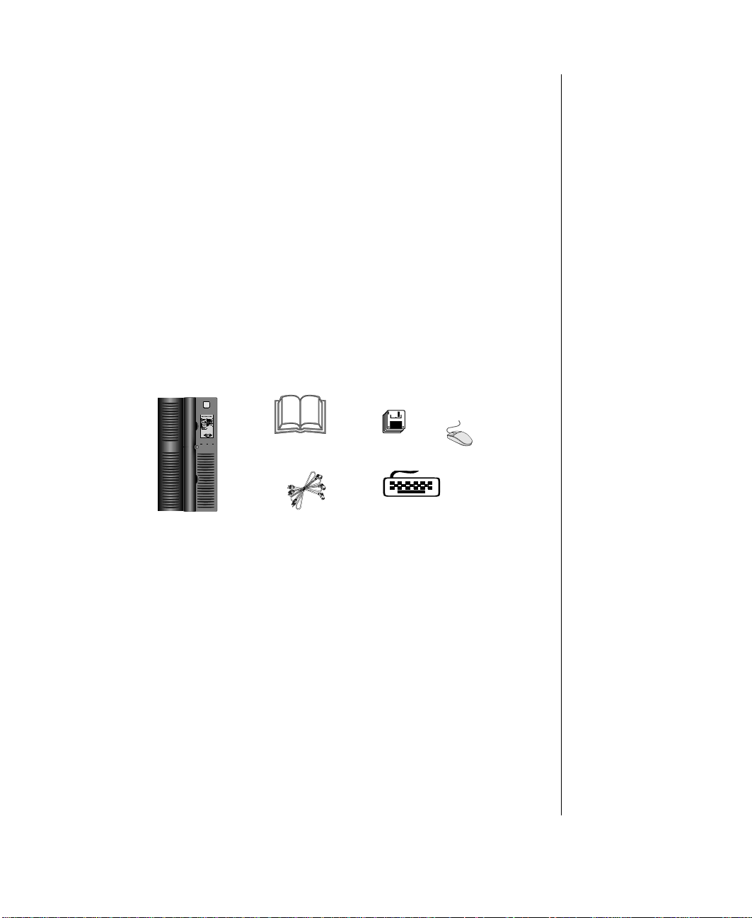
Inspecting the Conten ts
Unpack the product carton and inspect the contents. Standa rd systems
include the follo wing items.
- User’s Guide
- Technical Reference
Enhan
iliti
iliti
M
Check the packing list to ve rify that all equi pment and associated manuals
are included in your sh ipment. Inspect e verything carefull y. If you suspect
any damage from shipping, contact Technical Support.
When returning equipment to the factory, you must first obtain a Return
Material Authorization (RMA) number from Technical Support.
Keep the product carton and foam packing, in case y ou hav e to send the
system out (i.e. for repair , etc.) I f you return y our system to the
manufacturer in differ ent packaging, you r warranty ma y be v oided.
Assembling Your System 3
Page 20

Connecting Peripherals
Refer to the illustrations and procedures belo w w hen connecting
peripherals to your s ystem.
1. Connect the keyboard to the k eyboard port.
2. Connect the monitor video cab le to the video port. The location of the
3. Connect the monitor pow er cable to an A C outlet or preferab ly, a surge
4. Verify that the Voltage Selection Switch on each po w er suppl y is set
Using the pow er cab le(s) suppli ed with your syst em, connect the the po w er
supply to an A C outlet. If your system is eq uipped with more than one
pow er suppl y, connect each of the po w er supplies to a separ ate A C outlet.
4 Gateway ALR 9000 User’s Guide
Figur e 1: Connecti ng P er ipher als
port may vary depending on the type of video card installed in y our
system.
control outlet station.
for the proper volta ge in your area (115V or 230V).
Page 21

Powering Up the System
• Press the ON/OFF switch on the front panel, a nd the green LED on
the front panel will illuminat e ON.
• If you turn off your sys tem, wait at least ten seconds bef ore turning
the system back on.
• The system self-checks the memory even i f a monitor is not
connected. If a monitor is conne cted and po w ered on, the screen
will display the power-up sequence.
• If more than one CPU is installe d , the syst em will displa y wh ich
CPU it is currently testing.
• If any errors are encountered , y our system will di spla y them on the
monitor.
• If a monitor is not connected or th e system is unab le to displa y an
error, an error beep code will sound.
If the system encounters an error , it will most lik el y be a nonfatal one,
meaning, the system will function until the error can be corrected (usually
through the BIOS Setup). In the rare cas e of a fatal error, cont act your
T ec hnical Support field service support.
Powering Up the System 5
Page 22

6 Gateway ALR 9000 User’s Guide
Page 23

Chapter 2:
System Features
Contents
Basic Architecture................................................... 8
Front Panel............................................................... 9
Rear Panel.............................................................. 12
System Board.........................................................15
Page 24

Basic Architectur e
The following features are standar d equipment for this syste m:
• Intel Pentium® Pro® processor
• Onboard symmetrical processing supporting up to six P enti um®
® processors
Pro
• 128-MB Error Checking & Correction (ECC) RAM, expandable
to 2-GB on SIMM card and up to 4-GB on optional DIMM card
• 32-bit PCI and EISA bus master; 64-bit da ta path betw een
processors and memory (256-bit with 4-wa y memory interlea ve)
• 2-MB DRAM PCI graphics adapter
• SCSI CD-ROM dri ve
• 1.44-MB 3.5-inch floppy dri ve
• Integrated flopp y driv e controller supporting up to t w o flopp y
devices of 1.44-MB and 2.88-MB formats
• Po w er Supply Subs ystem with three redundant/ hot-pluggable N+1
pow er suppl y modules (tw o 35 0-Watt powe r supplies plus one 350W att spar e)
• InforManager™ with client softw are for continuous monitoring
and reporting of system devices and en vironment s
8 Gateway ALR 9000 User’s Guide
• Phoenix upgradable Flash BIOS supporting DMI 2.0
Page 25

Front Panel
Figur e 2: Front Panel
Reset Switch
The system reset switch allows you to reset the system without having to power
it off and then on again.
3.5-inch Floppy Disk Drive
The standard system is equi pped with o ne half- heigh t 1.44- MB 3.5-i nch fl oppy
disk.
SCSI CD-ROM Drive
The system comes standard with one factory-installed SCSI CD-ROM drive.
Front Panel 9
Page 26

Bezel Doors
The top bezel door off ers access to the P o w er , Reset , and Ke yboard Inhibit
switches, as w ell as the 3.5-i nch and the upper 5.25-inch dri ves. The lower
bezel door offers access to the lo w er 5.25-inc h driv es.
Storage Bays
The system is equipped with fourteen storage ba ys w hich can support up to
78-GB of fixed media storage.
• three 3.5-inch ba ys: one with factory-installed 1.44-MB 3.5-inch
floppy disk ette dri ve, one ex ternal front-accessib le ba y, and one
internal-accessible ba y
• five 5.25-inch bays (one with factory-installed SCSI CD-R OM
Drive): all front-accessib le and can support an y 5.25-inch de vice or
3.5-inch device with a s pecial mounting bracket
• six 3.5-inch Quick Hot Swap ba ys housed i n a RAIDCage
(RAIDCage 6D) which also sup ports 1-inch and 1.6-inch de vices
Keyboard Inhibit Switch
The keyboard inhibit s witch can be loc ked to pre vent una uthorized access
to the system. When locked , th e keyboard wil l not function.
Power On/Off Switch
The pow er s witch is a rocker a ssembl y. Rock the switch up (I) to pow er the
system ON, rock the s witch do wn (0) to pow er the system OFF.
LED Indicators
The front panel includes three LED indi cators that signal a specific
message when illuminated:
LED Meaning (when illuminated)
Power Power is ON.
Hard Disk Activity Hard disk is in use.
Reserved (for future use)
10 Gateway ALR 9000 User’s Guide
Page 27

Bezel Keylock
The keylock allo ws y ou to lock the bez el doors to pre vent access to the
front panel.
InforManager™ (IFM) LCD
The system is equipped with a touchscreen LCD control panel that displa ys
the status of the InforManager™ and allo ws the user acces s to all of its
functions:
• System Monitor
• F an Monitors
• Temperature Monitors
• Po w er Suppl y Monitors
• Activity Monitors (CPU and disk dri ve s)
• Rear and Front Panel Monitors
• System Information
For det ailed information re garding the functi ons and usage of the
InforManager™ LCD panel, refer to Chapter 3.
Front Panel 11
Page 28

Rear Panel
The rear panel of the system is equipped with I /O P orts, connectors, and
switches as illust rated and explai ned belo w.
ECC Reset Switch
This switch allo ws y ou to reset t he system when a memory fault occurs.
Parallel Port
Connect parallel de vices such as parallel printers and scanners to this port.
12 Gateway ALR 9000 User’s Guide
Figur e 3: Rear Panel
Page 29

Mouse Port
This port supports any mouse with a miniature circular DIN (mini- DIN)
connector .
Keyboard Port
This port supports any keyboard with a mini ature circular DIN (mini-DIN)
connector .
Serial Port 1
This is a high-speed serial port w hich uses the F irst-In-F irst-Out (FIFO)
protocol. If you ha ve a serial mouse, connect it to this port. Other serial
devices such as ser ial printers or modems can al so be connected thi s port.
Serial Port 2
This is a high-speed serial port w hich uses the F irst-In-F irst-Out (FIFO)
protocol. Serial de vices such as serial printers or modems can also be
connected this port.
Note:
If your mouse has a miniDIN connector, you must
connect it to the Mouse
Port.
Power Supply Fault Reset Switch
In the event of a po w er suppl y failure, pressing this switch tu rns off the
alarm signal and resets the po wer s upply.
Chassis Keylocks (2)
The rear panel is designed wit h two loo p keylocks i n which y ou can install a
padlock each to secure the right a nd left panels.
Redundant Power Supply Subsystem
Standard equipment includes three hot -pluggabl e, redundant po w er
supplies (tw o 350-Watt N+1 modules and one spare). The system can
support up to four identical po w er suppl y modules w hich yield a redundant
pow er of 700-Watts.
Rear Panel 13
Page 30

• P o w er Supply LED , w hen lit, indic ates that the po w er suppl y is
active.
• On/Off Switch turns the po w er supply on o r off.
• Pull-Out Handle allows ease of installation or replacement of the
pow er suppl y.
AC-In Power Connector A
This socket con ve ys po wer t o po w er supplies 1 and 2. Connect the system
pow er cab le to this sock et and to an A C outlet .
AC-In Power Connector B
This socket con ve ys po wer t o po w er supplies 3 and 4. Connect the system
pow er cab le to this sock et and an A C outlet.
14 Gateway ALR 9000 User’s Guide
Page 31

System Board
The system board functions as the main int erface betw een the processor ,
memory , and peripherals. Belo w is an illustration of t he system board.
Figur e 4: Syst em Board
System Board 15
Page 32

CPUs and CPU Slots
The standard system is equipped with one P entium Pro chi p installed on
CPU card A which is installed i n CPU card slot A. In CPU card slot B, a
terminator card is installed in place of an optional second CPU car d B.
Figur e 5: CPU Car d
Symmetrical Multi-Processing
Symmetrical Multi-Processing SMP e nables all CPUs in the system
simultaneously to service interrupts, access system memory , and perf orm I/
O operations. If your operati ng system does not support SMP, the system
adjusts the processing mode to Asymmetrical, me aning only t he first CPU
accepts I/O interrupts, while the successi ve CPUs accept onl y
interprocessor interrupts.
Voltage Regulator Module
Each CPU must have a dedicated vol tage regulato r module (VRM) which
adjusts the voltage suppli ed to the CPU.
Floppy Drive Controller
The floppy dri ve controll er can support up to tw o devi ces of 1.44-MB or
2.88-MB format.
16 Gateway ALR 9000 User’s Guide
Page 33

Hard Drive Controller
The hard driv e controller is an i ntegrated dual-channel PCI/I DE interface is
capable of controlling up t o four IDE devi ces and supporting PIO Modes 0-
4.
Adaptec® AIC™-7880 SCSI Controller
This is a high-performance, PnP compliant, single-chip PCI local bus-t oUltraSCSI master host adapter . I ts pin compatibility p ro vides a direct
upgrade path for higher I/O bandwidth requirements with data rates of 20MB/sec in the 8-bit mode and 40-MB/se c in the 16-bit mode.
Additional features:
• Full 32-bit PCI bus master implementation maximiz ing data
transfer on PCI local bus at 133-MB/sec dat a bursts
• BIOS Developer’s Kit (BDK) allowing easy customiza tion of
system BIOS code for various feat ures
• SCAM (SCSI Configured Automatically) Level 1 f or W indo ws
® enabling automatic configuration of new de vices without
95
having to reboot the system.
• Wide SCSI configuration supporting up to 15 connected SCSI
peripherals
• Multithreading support for up to 255 simultaneous I/O tas ks
• Advanced SCSI I/O cell ensur ing data integrity b y automaticall y
and continuously adjus ting sle w rate to compensate f or SCSI bus
loading
• Driver support for all major operating systems
I/O Card Slot
The I/O ports are housed on an I/O card whic h is factory installed in this
slot.
System Board 17
Page 34

Expansion Slots
There are a total of tw elve e xpansion slots on t he system board:
• seven 32-bit PCI slots
• four 32-bit EISA slots
• one shared PCI/EISA slot
Memory
The system comes standard with 128-MB Error and Correction (ECC)
RAM installed on the SIMM card. The s ixteen SIMM sockets ( 8 ro ws/
banks) can support up to 2-GB of ECC memory . The optional 2 ca rd
supports up to 4-GB of ECC memory.
InforManager™
The system is equipped with InforManage r (IFM), a special featur e
consisting of both hardw are and softw are designed to monitor a nd report
the operation status of the system and i ts device s: CPUs, po w er supplies,
RAM, ambient temperatures, volt ages, and fan operation. One w a y to
monitor these device s is using the InforMa nager LCD panel (see Chapter
3).
Also supplied with this system are cl ient-server monitoring ut ilities with
two special features (currently av ailab le in the W in dow s NT™ utilities
only):
18 Gateway ALR 9000 User’s Guide
Figur e 6: Memory Car d
Page 35

• ActiveCPR (Central Processor Recovery) designed to pre serve the
processors from damage from e xtreme temperatures and voltages
• Server Watchdog™ monitors the system for “hangups ” and
reboots after a designated per iod of time.
For det ailed information about the Infor Manager utilitie s, refer to the
InforManag er™ User’s Guide.
System Board 19
Page 36

20 Gateway ALR 9000 User’s Guide
Page 37

Chapter 3:
InforManager™ LCD
Contents
About InforManager™ ......................................... 22
CPU Menu.............................................................24
RAM Menu............................................................25
Disk Activity Menu............................................... 26
Fan and Temperature Menu.................................. 27
Power Menu...........................................................28
Lock Menu.............................................................29
System Menu......................................................... 30
Alarm/ID/Speaker Menu....................................... 33
System Tolerances................................................. 34
Page 38

About InforManager™
Important!
To ensure data integrity and
optimum per forman ce of the
IFM, access an d ope rati on
of the LCD should be
restricted to qual ifi ed
personnel.
Note:
The LCD energy-saving
feature is pr e set and cann ot
be changed or disabled.
The system is equipped with InforManage r™ (IFM), a special f eature
consisting of both hardw are and softw are designed to monitor a nd report
the operation status of the system and i ts device s: CPUs, po w er supplies,
RAM, ambient temperatures, volt ages, and fan operation.
A microcontroller chip embedded on the system board c hecks the
performance of various de vices install ed in the computer as w ell as their
temperature and voltage lev els.
The touchscreen LCD on the front panel is pro grammed with fully
functioning menu screens, allo wing access to all system functions .
• System Monitor
• F an Monitors
• Temperature Monitors
• System Po w er and P o w er Suppl y Monitors
• Activity Monitors (CPU and disk dri v es)
• Side Panel Monitors
• System Information
T o access an y menu screen, gentl y touch the i con of the de vice you wish to
see. The LCD will then displa y the status or a sub-menu of the de vice. You
can also scroll through the menu scr eens b y touching the highlighte d
arrows at the bottom of the LCD.
22 Gateway ALR 9000 User’s Guide
As an energ y-sa ving feature, the LCD screen automatic ally goes “blank”
(sleep mode) after five minutes of inacti vit y . A t ouch anyw here on the
screen will bring the displa y back on.
Page 39

The diagram below ill ustrates the dif ferent menu and sub -menu screens
programmed on the LCD panel. Refer to the follo wing sections for more
specific information about each menu screen.
Important!
A flashing button on the
Main menu screen indicates
an error condition.
Figur e 7: Dia gr am of LCD Menus
About InforManager™ 23
Page 40

CPU Menu
The CPU menu displays the st atus (Good or F ail ) and current activity (Idl e
or Busy) of each CPU .
Figur e 8: CPU Menu
24 Gateway ALR 9000 User’s Guide
Page 41

RAM Menu
The RAM menu displays the current amount of RAM and its sta tus (Good
or F ail). The ECC Error Reset button is also accessib le through this menu.
Figur e 9: RAM Menu
RAM Menu 25
Page 42

Disk Activity Menu
The Disk Activity menu displa ys the dri ves currently installed and their
activity w hich is indicated b y a doub le dash underneath BUSY or IDLE.
Figur e 10: Disk Acti vity Menu
26 Gateway ALR 9000 User’s Guide
Page 43

Fan and Temperature Menu
The activity and speed (RPM) of bot h CPU fansinks and chassis fans are
display ed on these menus.
Normal fan operation is indicated by a “ rotating” fan icon. If a fan
encounters a problem, its corresponding fan icon and RPM on the LCD
readout will begin to fl ash instead.
A submenu displays the temperature of each CPU as w ell as the internal
and external ambient temperatures. Normal te mperature is indicate d by t he
continuous rising and falling motion of the “mercury” inside the
thermometer icon. When the temperature falls out of range, motion in the
thermometer icon will stop, and the temperature readout will be gin to flash
instead.
Figur e 11: Fan and T emperature Menu
Fan and Temperature Menu 27
Page 44

Power Menu
The Po w er menu screen di spla ys the v oltages associated wit h the system
including the voltage applied to each CPU, voltages supplied to t he system
board , and the vol tages supplied to the periphe rals.
When a voltage is with in normal range, the pointer in the v oltage meter
icon mov es laterall y back and forth. If an out-of-range v oltage occurs, t he
pointer will stop completel y and the v oltage readout will start flashing
instead.
A submenu displays the status (GOOD or FAIL) of the po wer supplies.
28 Gateway ALR 9000 User’s Guide
Figur e 12: Power Menu
Page 45

Lock Menu
The Lock menu displays t he status (OPEN/CLOSE) of the side pane ls. A
flashing icon indicates that the c orresponding panel is open. When a panel
is closed , the icon remain s static.
Figur e 13: Loc k Menu
Lock Menu 29
Page 46

System Menu
All currently installed firmware, i.e., system BIOS, IFM BIOS, and LCD
BIOS, as well as the qu antities of hard ware de vices instal led are displa y ed
on this menu.
Communication between the LCD and IFM is designated b y the
continuously incre asing and decreasing number of dashes underneath the
LCD & HOST IFM Communication line.
Non-communication is indicated b y a notation “ NONE” in the place of
dashes as well as a beeping alert.
30 Gateway ALR 9000 User’s Guide
Figur e 14: Syst em Menu
Page 47

LCD Reset
In the event of non -communication betw een the LCD and host I FM,
perform the steps below:
1. Reset the LCD panel by pressi ng the LCD Reset button whic h is
accessible through t he Main scr een submenu as sho wn belo w.
Figur e 15: LCD Reset Menu
2. If there is still no communication betw een the LCD and host IFM,
then reboot the system.
3. If there is still no communication after s teps 1 and 2 ha ve been
performed, then contact Technical Support.
System Menu 31
Page 48

ID Setup
T o estab lish communicatio n betwee n the LCD and host IFM, the LCD
must maintain an ID number that matches the ID number on the s ystem
board. The ID numbers are displa yed in the ID SETUP submenu (see) as
follows:
• ID Selected displays t he LCD ID number .
• ID A vai lable displa ys the ID number on t he system board.
In the event thes e ID numbers do not match, communication will cease.
You must restore communication by performing the follo wing:
1. Press the Reload ID butt on to automaticall y reload an LCD ID
number that matches the current ID number on the system board.
2. Press the Save Set up button which will displa y a submenu. Then,
press the Accept button to confirm the change you just made.
If you need to change the ID number on the system board, you must do so
through the BIOS Setup Program.
32 Gateway ALR 9000 User’s Guide
Page 49

Alarm/ID/Speaker Menu
The Alarm Menu allows y ou to turn the speaker OFF or ON . The default is
ON. You can also access ID Setup and LCD Reset from this menu.
Figur e 16: Alar m/ID/Speaker Menu
Alarm/ID/Speaker Menu 33
Page 50

System Tolerances
Important!
This data file is used by the
system to deter min e t he
system tolerances. The
wording an d form at are
essential and should NEVER
be changed.
Note:
"-98" is a key number used
to indicate that there is no
tolerance value for this item.
The following table contains the toleranc e values t hat ha ve been set for this
system.
Table 1:
Field Low Typical High Definition
fan 1200 3000 -98 system fan speed
processorfan 0 3600 -98 processor fan speed
processortempera-
ture
processorvoltage 2.1 3.3 3.7 processor core voltage
internalambient -98 95 113 internal ambient temperature
externalambient -98 78 95 external ambient tempera-
drivecage -98 95 122 drive cage temperature
systemboard3VP 3.0 3.3 3.6 system board voltage 3.3V
systemboard5VP 4.5 5.0 5.5 system board voltage 5.0V
systemboard5VN -5.5 -5.0 -4.5 system board voltage -5.0V
systemboard12VP 10.8 12.0 13.2 system board voltage 12V
systemboard12VN -13.2 -12.0 -10.8 system board voltage -12V
peripheral5VP 4.5 5.0 5.5 peripheral board voltage 5V
peripheral12VP 10.8 12.0 13.2 peripheral board voltage 12V
-98 100 176 processor temperature
ture
34 Gateway ALR 9000 User’s Guide
F ans speeds are measured in rev olutions per minute (RPM), temperatures in
degrees F ahrenheit (°F), and v oltages in Volts (V).
Page 51

Chapter 4:
Troubleshooting
Contents
Handy Checklists...................................................36
Looking Things Over..................................... 36
Verifying Your Configuration....................... 36
Common Problems................................................37
Drive Problems...............................................38
Monitor Problems........................................... 39
Printer Problems............................................. 40
Installation Problems...................................... 41
Page 52

Handy Checklists
Important!
DO NOT, under any
circumstances, return any
equipment without first
obtaining a Return Material
Authorization (RMA) number
from Technical Support.
If your system does not oper ate correctly, re-read the instructions for the
procedure(s) you ha ve perf ormed. If an error occurs within an application,
consult the documentation supplied wit h the softw are.
If the suggestions in this sec tion are not helpful, t ry the Technical Support
department.
The following checks should be performed in the e vent of a prob lem. If
these checks do not help solv e the problem, cons ult Technical Support.
Looking Things Over
Sometimes, the simplest things can cause troub le. Before po w ering up the
system, perform the following checks :
1. Is the pow er cord connected to the PC and an A C outlet?
2. Is the AC outlet suppl ying po w er?
3. If a pow er s trip is used, is it switched on?
4. Are the voltage select ion swi tches on the po w er suppl y set for the
proper voltage (115V or 230V)?
36 Gateway ALR 9000 User’s Guide
V erifying Y our Configuration
If your system is not operati ng correctly, the BIOS may contain an in v alid
configuration parameter. Enter the BIOS pro gram and check your
configuration settings. For detail ed information regarding the BIOS
program, refer to BIOS Setup section in your Technical Reference manual .
Page 53

Common Problems
Table 2:
Problem Probable Cause Solution(s)
The system will
not power ON.
The system does
not display the
date and time
correctly or at all.
The Power LED is
flashing.
The Power LED
continues to flash
after ECC reset.
The system is not connected to an AC outlet.
The voltage-selection
switch is not set correctly.
The date and time parameters in BIOS Setup may
be set incorrectly.
The backup battery may
need to be replaced.
ECC memory failure has
occurred.
A DIMM was incorrectly
installed.
A DIMM is not functioning
properly.
Check the power cable and
make certain it is connected to
an AC power source.
Make certain the voltage-selection switch reflects the correct
power source.
Enter the BIOS Setup program
and correct the date and time
settings.
Contact Technical Support for
assistance.
Press the Keyboard Inhibit
Switch IN and then OUT.
NOTE: If the Keyboard Inhibit
Switch is already in locked position (IN), you must first unlock it
(OUT) and then lock it back (IN)
to reset the ECC memory status
and the Power LED.
Check the DIMM for proper
installation
Replace the faulty DIMM.
Common Problems 37
Page 54

Drive Problems
Table 3:
Problem Probable Cause Solution(s)
The system will
not boot.
The diskette LED
illuminates but
files cannot be
accessed.
Files cannot be
written to the disk
or diskette.
Insufficient space
on the drive.
A file cannot be
read from the
disk or diskette.
The hard disk is not formatted.
The disk is too slow to be
recognized by the system
in time.
A boot file was not found. Try booting from a bootable
The disk parameters in
BIOS Setup are incorrect.
The diskette was loaded
incorrectly.
The diskette is damaged. Run CHKDSK (DOS) or another
The file is corrupted (bad). Try the diskette on another
The disk is write protected. Remove the write protect tab or
The wrong drive letter was
specified.
The disk is not formatted. Format the disk.
The drive you are trying to
write to is full.
The file you wish to copy is
too large to fit on t he specified disk or diskette.
The wrong drive letter was
specified.
The disk is not formatted. Format the disk.
Boot from a floppy diskette,
then format the hard drive.
Follow the instructions on the
screen to try the boot again.
floppy diskette.
Enter BIOS Setup and check
the disk parameters.
Remove the diskette, and load it
properly into the drive.
disk-verification utility to check
the disk’s integrity.
computer. Re-copy the file if
necessary.
switch from the disk.
Check to ensure the drive LED
illuminates when you issue the
write command. If it doesn’t, try
another drive letter.
Remove files from the disk or
write to another device.
Compress the file and try again,
or write to another disk.
Check to ensure the drive LED
illuminates when you issue the
read command. If it doesn’t, try
another drive letter.
38 Gateway ALR 9000 User’s Guide
Page 55

Monitor Problems
Table 4:
Problem Probable Cause Solution(s)
The monitor will
not power-up.
The monitor’s
power light is on
but nothing displays on the
screen.
The characters
on the screen are
dim.
The color monitor displays the
Microsoft Windows application
in black and
white.
Characters on the
screen are garbage.
The power cord is not connected to an AC outlet.
The monitor’s power
switch is not in the ON
position.
The monitor’ s contrast and
brightness knobs are set
too low.
The computer system is
not powered-up.
The monitor’s video cable
is not connected to the
system’s video port.
The video cable’s connector has a bent pin.
The monitor’ s contrast and
brightness knobs are set
too low.
The system was poweredup before the monitor.
The video cable is damaged.
The video card is faulty. C all Technical Support.
Check the power cord and
make certain it is connected to
a working AC outle t .
Make certain the switch is in the
ON position.
Adjust the brightness and contrast knobs until you can see
the display.
Power-up the system.
Check the video cable and
ensure it is connected to the
proper port.
Check the cable’s connector
and repair if necessary.
Adjust the brightness and contrast knobs until you can see
the display clearly.
Exit from the WindowsMicrosoft Windows program
<Alt> + <F4>, then reset the
system.
Check the video cable for bent
pins or broken wires.
Common Problems 39
Page 56

Printer Problems
Table 5:
Problem Probable Cause Solution(s)
The printer will
not power-up.
The printer will
not print.
The printer prints
garbage.
(Serial printers)
The printer will
not print.
The power cord is not connected to a working AC
outlet.
The printer’s power switch
is not in the ON position.
The printer is off-line. Press the printer’s On-Line
The printer’s data cable is
not connected properly.
The printer’s data cable is
damaged.
The port is bad. Call Technical Support.
The printer’s data cable is
not connected properly or
is damaged.
The wrong data cable is
being used.
The baud rate for the serial
port does not match that
of the printer.
Check the power cord and AC
outlet.
Check the switch.
switch and make certain the
On-Line LED illuminates.
Check the cable and make certain it is connected to the correct port.
Check the cable for bent pins or
broken wires.
Check the cable and make certain it is connected properly and
not damaged.
Make certain you are using the
proper data cable.
Enter BIOS Setup and check
the ports parameters. They
should reflect the printer’s settings.
40 Gateway ALR 9000 User’s Guide
Page 57

Installation Pro blems
Table 6:
Problem Probable Cause Solution(s)
A drive is not recognized by the
system.
Memory errors
were detected
during the powerup sequence.
An adapter card
is not recognized
by the system.
The Power LED is
flashing.
The BIOS Setup program
reflects the wrong parameters.
The device is not formatted.
The device controller is not
configured properly.
Memory was added or
removed and the new configuration was not saved in
BIOS Setup.
A memory DIMM was
installed incorrectly.
A memory DIMM is not
functioning properly.
The interrupt and/or I/O
address is set incorrectly.
ECC memory failure has
occurred.
Enter the BIOS Setup program
and enter the appropriate
parameters for the device.
Format the drive.
Check jumpers and cable connections.
Enter BIOS Setup and save the
new memory configuration.
Check the DIMMs for proper
installation.
Replace the faulty DIMM.
Check the address configuration of the adapter card and
ensure it does not conflict with
another card in the system.
Press the Keyboard Inhibit
Switch IN and then OUT.
The Power LED
continues to flash
after ECC reset.
A DIMM was incorrectly
installed.
A DIMM is not functioning
properly.
NOTE: If the Keyboard Inhibit
Switch is already in locked position (IN), you must first unlock it
(OUT) and then lock it back (IN)
to reset the ECC memory status
and the Power LED.
Check the DIMM for proper
installation
Replace the faulty DIMM.
Common Problems 41
Page 58

42 Gateway ALR 9000 User’s Guide
Page 59

Chapter 5:
Maintenance
Contents
Cleaning the Mouse...............................................44
Cleaning the Keyboard.......................................... 45
Cleaning the Monitor Screen................................45
Page 60

Cleaning the Mouse
If the mouse pointer on the screen mo ve s erratically w hen you mo v e the
mouse, dirt is probably on the r ollers inside the mouse . In this case, clean
your mouse as follo ws.
Recommended T ools
• cleaning cloth
• adhesive t ape
• cotton swa b
• isopropyl alcohol
• cross-tip scre wdriv er
1. Shut down the system.
2. Remove the bottom co ver of the mouse. Depending on the model,
you may ne ed to first remove the screws t hat secure the cover. Set
aside screws.
3. Remove the ball out of the ball sock et.
4. Use adhesive t ape to pick up an y dust or lint on the s urface of the
5. With a cleani ng cloth, wipe a wa y dirt or lint inside the mouse-ball
6. If foreign matter is trapped insid e the socket o r on the rollers, use a
7. Allow surfaces to dry completel y after cleaning.
8. Return the mouse ball to the socket and replace the co v er .
9. If applicable, secure the co ver with the sc rews remo v ed previ ously.
44 Gateway ALR 9000 User’s Guide
mouse ball.
socket. Moisten the cloth wi th isoprop yl alcohol is neces sary .
cotton swa b dipped in isoprop yl alcohol to loosen i t.
Page 61

Cleaning the Keyboard
Occasionally, you should clean the k eyboard to fre e it of dust and lint
particles that may be trapped under the k eys. The e asiest w a y to do this it t o
blo w trapped dirt from the keys using an aerosol ke yboard cleaner w hich is
usually supplied wit h a stra w-like e xtension for hard- to-reach places.
If you spill liquid on the keyboa rd , follo w the steps belo w.
1. Shut down the computer and di sconnect the ke yboard.
2. T urn the ke yboard upside do wn for the liqui d to drain out. Allo w the
keyboard to dry o vernight before t rying to use it again.
3. After verifying that the system is of f, reconnect the k eyboard t o the
computer.
If the keyboard fails to wo rk after draining, cont act Technical Support.
Cleaning the Monitor Screen
Use a soft cloth and windo w cleaner to clean the monitor screen. Squirt a
little cleaner on the cloth and wipe the screen with the cloth.
Caution!
NEVER spray directly on the
monitor screen.
Cleaning the Keyboard 45
Page 62

46 Gateway ALR 9000 User’s Guide
Page 63

Index
A
About This Guide xiv
adapter card
alarm
B
baud rate 40
bezel doors
BIOS
BIOS Setup
bus master
C
CD-RO 10
CD-ROM
Conventions Used in this Guide
CPU
CPU card
D
DIMM 8, 37, 41
DMI
DRAM
E
ECC 8, 25, 37, 41
EISA
error
ECC
fatal error
F
fan 27
fansink
firmware
Flash BIOS
floppy disk
floppy drive
format
front panel
41
13, 33
10, 11
36, 37, 40, 41
5, 32
8
9
5, 16, 22, 24, 27, 28
16
8
8
8
5, 8
8
5
27
30
8
9
8, 10, 16
41
9, 11, 22
xv
G
graphics adapter 8
H
host IFM 31
humidity
I
I/O Ports 12
I/O ports
ID
IDE
InforManager
K
keyboard 2, 4, 45
keylock
L
LCD 11
LCD ID number
LED
M
memory 41
memory fault
microcontroller
mini-DIN
monitor
mouse
3
keyboard port
printer port
video port
keyboard
mouse
parallel
serial
40
4
13
13
12
13
32
17
8, 11
client software
11, 13
diagram
sleep mode
23
22
5, 10, 37, 40
12
13
2, 5, 45
44
22
4
8
32
Index IN-47
Page 64

N
N+1 8
terminator card
touchscreen
22
16
P
PCI 8
Pentium
peripherals
PIO Mode
power connectors
power supply
printer
problems
8
4
17
14
4, 8, 13, 14, 28, 36
40
37
common problems
installation problems
printer problems
37
40
41
R
RAIDCage 10
8, 22, 25
RAM
rear panel
redundant power
reset switch
Return Material Authorization (RMA)
13
13
9
3, 36
S
SCSI 8, 9 , 10
serial port
Serial printers
SIMM
SMP
speaker
storage bays
switch
system board
13
40
8
16
33
10
quick hot swap
ECC reset
keyboard inhibit
10
power
power supply fault reset switch
10
reset
10
12
10
32
13
V
video cable 39
video card
voltage
voltage regulator module (VRM)
voltage selection switch
39
28
16
4, 36
T
temperature 3, 22, 27
IN-48 Gateway ALR 9000 User’s Guide
 Loading...