

Page 1

Gateway
ALR 7200
User’s Guide
Part #8503435 A MAN SYS US 7200 USR G DE R0 7/98
In our effort to use nature’s resources efficiently and wisely, we print all manuals on recycled papers that meet the
minimum requirements established by the Federal EPA in its guidelines for recycled paper products.
Page 2

Notices
Copyright © 1998 Gateway 2000, Inc.
All Rights Reserved
610 Gateway Drive
N. Sioux City, SD 57049 USA
All Rights Reserved
This publication is protected by copyright and all rights are reserved. No part of it may be reproduced
or transmitted by any means or in any form, without prior consent in writing from Gateway 2000.
The information in this manual has been carefully checked and is believed to be accurate. However,
changes are ma de pe rio dic ally. These changes are incor por ate d in new er pu bli cati on ed iti ons.
Gateway 2000 may improve and/or change products described in this publication at any time. Due to
continuing system improvements, Gateway 2000 is not responsible for inaccurate information which
may appear in this manual. For the latest product updates, consult the Gateway 2000 web site at
www.gateway .com. In no event will Gateway 2000 be liable for direct, indirect, special, exemplary ,
incidental, or consequential damages resulting from any defect or omission in this manual, even if
advised of the possibility of such damages.
In the interest of continued product development, Gateway 2000 reserves the right to make
improvements in this manual and the products it describes at any time, without notices or obligation.
Trademark Acknowledgments
AnyKey, black-and-white spot design, ColorBook, CrystalScan, Destination, EZ Pad, EZ Point, Field
Mouse, Gateway 2000, HandBook, Liberty, TelePath, Vivitron, stylized “G” design, and “You’ve got a
friend in t h e bu si ne ss ” s log a n ar e r eg is t er ed t rad e ma rk s and “All the big trend s s t ar t in So u th D a ko ta ”
slogan, GATEWAY, and Gateway Solo are trademarks of Gateway 2000, Inc. Intel, Intel Inside logo,
and Pentium are registered trademarks and MMX is a trademark of Intel Corporation. Microsoft, MS,
MS-DOS, and Windows are trademarks or registered trademarks of Microsoft Corporation. All other
product names mentioned herein are used for identification purposes only, and may be the trademarks
or registered trademarks of their respective companies.
Copyright © 1998 Advanced Logic Research, Inc. (ALR)
All Rights Reserved
9401 Jeronimo
Irvine, CA 92618 USA
All Rights Reserved
This publication is protected by copyright and all rights are reserved. No part of it may be reproduced
or transmitted by any means or in any form, without prior consent in writing from ALR.
The information in this manual has been carefully checked and is believed to be accurate. However,
changes are ma de pe rio dic ally. These changes are incor por ate d in new er pu bli cati on ed iti ons. ALR
may improve and/or change products described in this publication at any time. Due to continuing
system improvements, ALR is not responsible for inaccurate information which may appear in this
manual. For the latest product updates, consult the ALR web site at www.al r.com. In no event will ALR
be liable for direct, indirect, special, exemplary, incidental, or consequential damages resulting from
any defect or omission in this manual, even if advised of the possibility of such damages.
In the interest of continued product development, ALR reserves the right to make improvements in this
manual and the products it describes at any time, without notices or obligation.
Trademark Acknowledgments
ALR is a registered trademark of Advanced Logic Research, Inc. All other product names mentioned
herein are used for identification purposes only, and may be the trademarks or registered trademarks
of their respective companies.
ii
Page 3

Contents
Preface ................ .............. .............. .......... .............. .............. ....v
About This Guide................................................................................... vi
Conventions Used in this Guide.......................................................... vii
Chapter 1: Getting S tarted ............. .......... ......... .......... .... ........1
Before You Begin.................................................................................... 2
Assembling Your System ....................................................................... 3
Inspecting the Contents.................................................................... 3
Connecting Peripherals.................................................................... 4
Powering Up the System......................................................................... 6
Quick Check..................................................................................... 6
Troubleshooting Guidelines............................................................. 7
Chapter 2: System Fe atures ......................... ......... ......... ..... ... 9
Basic Features........................................................................................ 10
Front Panel............................................................................................. 11
Storage Bays................................................................................... 11
Buttons............................................................................................ 12
LED Indicators............................................................................... 12
3.5-inch Floppy Disk Drive........................................................... 12
Bezel Door and Keylock................................................................ 13
Rear Panel.............................................................................................. 14
Power Supply Connectors.............................................................. 14
Expansion Slot Cover Plates.......................................................... 15
I/O Ports.......................................................................................... 15
Operating Systems................................................................................. 16
Chapter 3: Maintaining and Cleaning Your System ............. 17
Maintaining Your System..................................................................... 18
Maintaining Your Hard Drive ....................................................... 18
Computer Virus Notice.................................................................. 20
Important Safety Instructions......................................................... 22
Cleaning Your System.......................................................................... 24
Cleaning the Mouse........................................................................ 24
Cleaning the Keyboard................................................................... 24
Cleaning the Monitor Screen......................................................... 25
iii
Page 4

Cleaning the Computer and Monitor Cases.................................. 25
Appendix A: Regulatory Compliance Statements .................27
FCC Notice............................................................................................ 28
Industry Canada Notice........................................................................ 29
CE Notice.............................................................................................. 29
VCCI Notice ......................................................................................... 30
Australia/New Zealand Notice............................................................. 30
Index ....................................................................................... 31
iv Gateway ALR 7200 User’s Guide
Page 5

Preface
Contents
About This Guide ...................................................vi
Conventions Used in this Guide............................vii
Page 6

About This Guide
The purpose of this User’s Guide is to help y ou unpack, assemb le, and
install the system. This guide provides step-by-step setup and o perating
instructions along with detailed illu strations throughout t he document.
Below is a summary of the sections to f ollo w:
Chapter 1: Getting Started co vers inf ormation about the internal and
external features as w ell as the syst em architecture and supported operat ing
systems.
Chapter 2: System Features expl ains the main features of your system,
including ho w to assembl e it, identifying connec tors and arranging your
workspace.
Chapter 3: Maintaining and Cleaning Your System explains how to
perform routine maintenance and cleaning on y our system.
We recommend you take time to r ead through the manual bef ore using the
system. If you encounter a prob lem, refer to the h andy troublesho oting
section in this guide.
vi Gateway ALR 7200 User’s Guide
Page 7
Conventions Used in this Guide
Note:
This is an example of an
important note that may
appear in the manual.
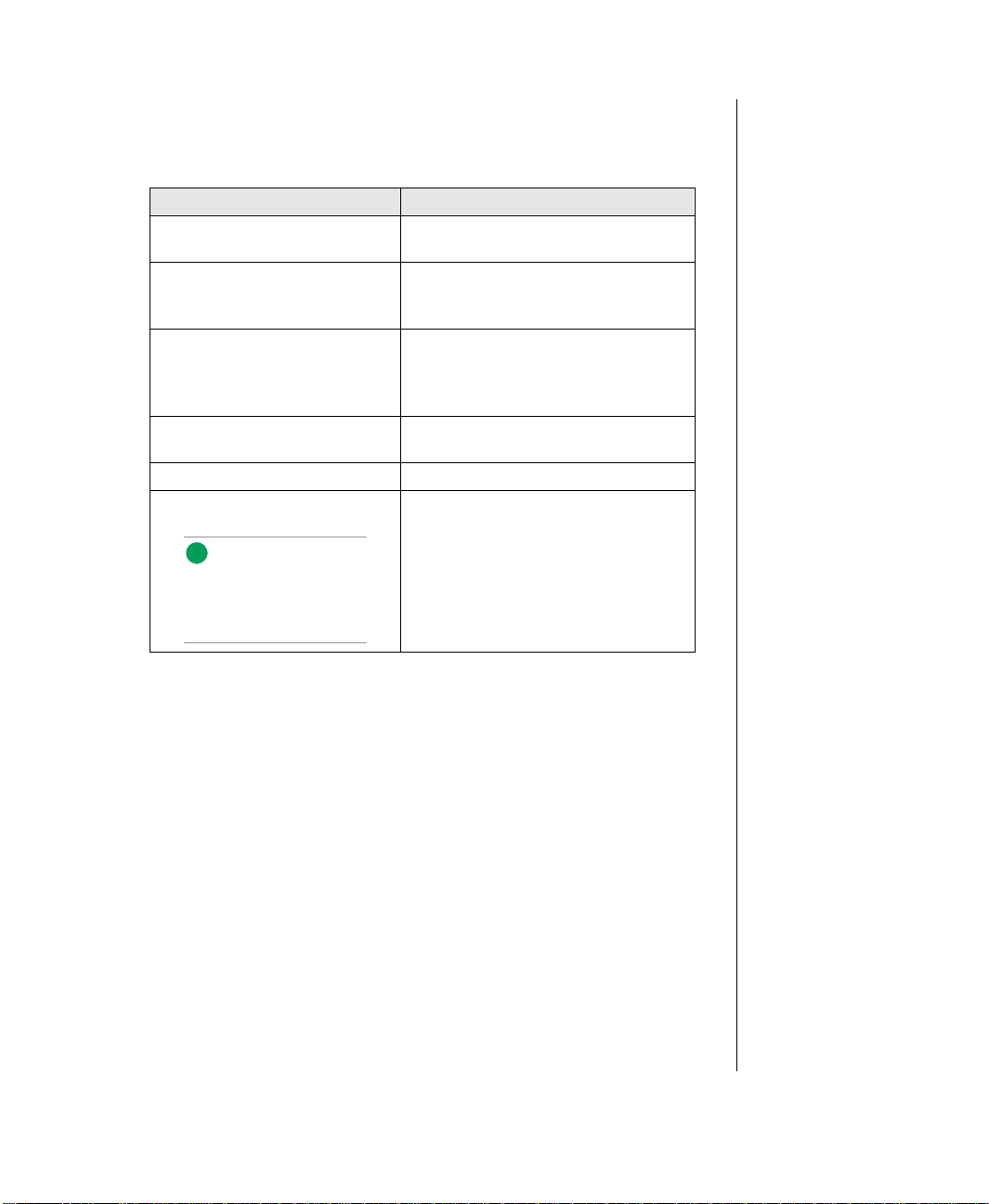
Throughout this booklet, you will see the fol lo wing con ventions :
CONVENTION DESCRIPTION
ENTER
CTRL + ALT + DEL
Setup
System User’s Guide Names of publications and files are
RUN
Sidebars Sidebars denote critical information
A key name corres ponds to a key on
the keyboard.
A plus sign indica tes that the keys on
either side of it must be pressed
simultaneously.
Commands to be entered as well as
messages that appear on your
monitor are printed in bolded “Arial
Narrow” font .
italicized.
Options to select are boldfaced.
such as war nings, important
information, and important notes.
Conventions Used in this Guide vii
Page 8

viii Gateway ALR 7200 User’s Guide
Page 9

Chapter 1:
Getting Started
Contents
Before You Begin.................................................... 2
Assembling Your System........................................ 3
Inspecting the Contents.................................... 3
Connecting Peripherals.................................... 4
Powering Up the System......................................... 6
Quick Check..................................................... 6
Troubleshooting Guidelines............................. 7
Page 10

Before Y ou Begin
Congratulations on your purchase. W ith the arriv al of your ne w system, you
are probabl y eager to assemb le the computer and ha ve it operat ing. This
section helps you accompli sh the follo wing:
• Assembling the system
• Connecting the monitor and keyboar d
• Po w ering up the s ystem
Carefully read and f ollo w these instructions to e nsure your syst em operates
correctly.
2 Gateway ALR 7200 User’s Guide
Page 11

Assembling Y our System
1. Prepare a clean, flat, and firm surface for your computer . Allo w at
least three inches at the r ear of the chassis for cabling and ai r
circulation.
2. Protect your computer from e xtreme temperature and humidi ty. Do
not expose your co mputer to direct sunlight , heater ducts, and other
heat-generating objects.
3. Keep your sys tem a wa y fr om equipment that generates magnet ic
fields. Even a telephone placed too closely to the sys tem may cause
interference.
4. Protect your system against AC line spikes b y using a 3-prong , 115-V
or 230-V (depending on the voltage s upplied in your locality), and an
AC sur ge control outle t station. The syst em includes a 300W po w er
supply.
Inspecting th e Contents
Unpack the carton and inspect the contents. Standar d systems include th e
following items:
• System Unit
• Power Cable
• User’ s Guide
• Maintaining and Troub leshooting
• Utilities
• Enhanced Keyboard
Check the packing list to ensure al l equipment and associated manuals are
included in your shipment. Inspect ev erything carefull y.
Important!
Keep the product carton
and foam packing, in case
you have to ship the
system. If you return the
system in different
packaging, your warranty
may be voided.
Assembling Your System 3
Page 12
Connecting Peripherals
Note:
Shielded cables are
required by the FCC.
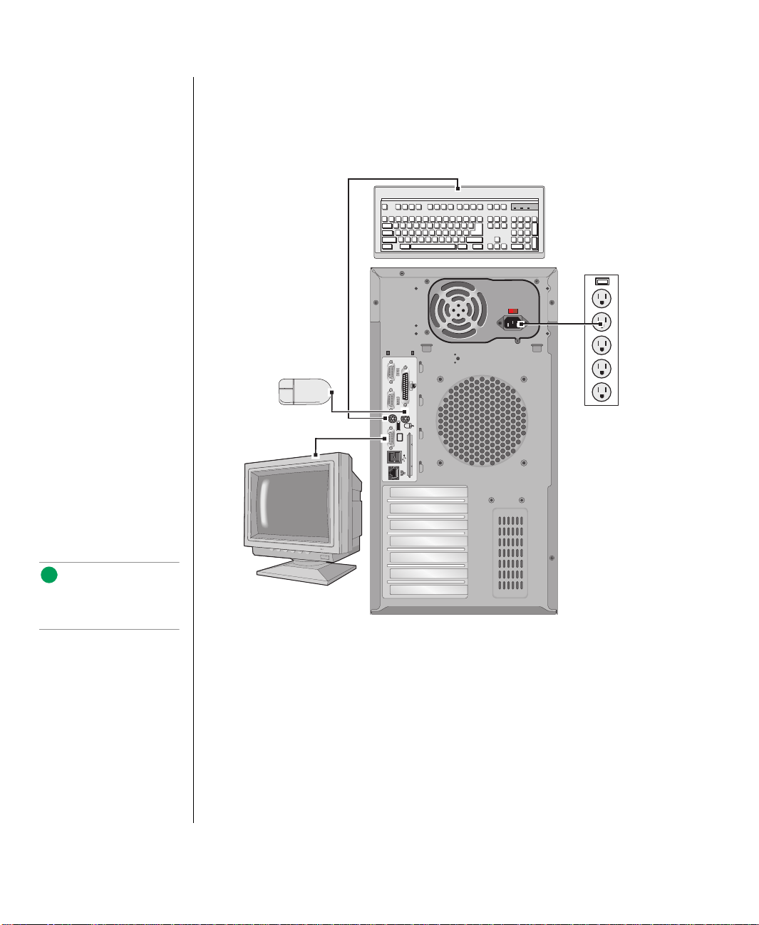
Refer to Figure 1 and the following procedures w hen connecti ng optional
peripherals to your s ystem.
4 Gateway ALR 7200 User’s Guide
Figur e 1: Connecti ng P er ipher als
1. Connect the keyboard and mouse to thei r respecti ve ports, using the
pictures embossed on the system’s back panel as a guide.
2. Connect the monitor video cab le to the video port. The location of the
port may vary depending on w hether you use th e integrated video or a
video card.
3. Connect the monitor pow er cable to an A C outlet or preferab ly, a surge
control outlet station.
Page 13

4. Verify that the Voltage Selector Switch on the po wer s upply is se t for
the proper voltage (1 15V or 230V).
5. Connect the system po w er cable t o the A C-In po w er sock et on the
pow er suppl y.
6. Connect the other end of the system po w er cab le to an A C outl et.
Assembling Your System 5
Page 14

Powering Up the System
Warning!
The bezel door must be
closed and locked while the
system is running.
Note:
Under no circumstances
return any equipment
without obtaining a Return
Material Authorization
(RMA) number.
Press the On/Off switch on the front panel, and the green LED on the front
panel will illuminate ON.
If you turn off y our system, y ou must w ait at least ten se conds before y ou
turn the system back on.
The system self-checks the memory even i f the monitor is not connec ted. If
the monitor is connected and po w ered ON, the scre en displays the pow er -up
sequence.
• If more than one CPU is installed, the system displays w hich CPU
it is currently testing.
• If any errors are encountered, your system displa ys them on the
monitor.
• If a monitor is not connected or th e system is unab le to displa y an
error, an error beep code sounds.
• If the system encounters an error , it is most l ikel y a nonfatal one,
meaning the system will function until the error can be corrected
(usually through the BIOS Setup) .
6 Gateway ALR 7200 User’s Guide
Quick Check
If your system does not oper ate correctly, re-read the instructions for the
procedure(s) you ha v e performed. If an error occurs within an application,
consult the documentation supplied wit h the softw are.
This section identifies solutions to common problems. If the suggestions i n
this section are not helpful , try looking up the problem in t he
and Tr oub leshooting Guide
. In the event of a problem, the follo wing checks
should be performed:
Maintaining
Page 15

Looking Things Over
Sometimes, the simplest things can cause troub le. To avoi d unnecessary
service calls, be sure you check o v er the basi cs before you call for support.
In any complex sy stem, there is potential for a forgotten c onnection, a
forgotten sw itch or a loose connector. Before pow ering up the sys tem,
perform the following che cks:
• Is the pow er cord c onnected to the CPU system and an A C outlet?
• Is the AC outl et suppl ying po w er?
• If a pow er stri p is used, is it switched on? Is the cir cuit breaker set ?
• Does the voltage select ion switch on t he system’s pow er suppl y
reflect the proper v oltage?
V erifying Y our Configuration
If your system is not ope rating correctly, the BIOS may contain an in valid
configuration parameter. Enter the BIOS pro gram and check your
configuration settings.
T roubleshooting Guidelines
As you troubleshoot y our system, k eep the follo wing guidel ines in mind:
• Never remo v e the system co v ers while the system is po w ered up.
• Do not attempt to open the monitor , it is e xtremel y dangerous.
Even if the monitor po wer is disconnected , stored ener gy within the
monitor’s components can cause a painful or harmful shock.
• If a peripheral such as the k eyboard, mouse, drive, or pri nter does
not appear to w ork, ensure that all con nections are secur e.
• If the screen displa ys an error message, write it do wn, wo rd-for-
word. You may be ask ed about it w hen calling Technical Support.
• Only qualified personnel should open the system for maintenanc e.
• If you feel you ar e qualified to maintain the system yourself, make
certain you are properl y grounded before opening the syste m
chassis.
Powering Up the System 7
Page 16

8 Gateway ALR 7200 User’s Guide
Page 17

Chapter 2:
System Features
Contents
Basic Features........................................................ 10
Front Panel............................................................. 11
Storage Bays................................................... 11
Buttons............................................................ 12
LED Indicators............................................... 12
3.5-inch Floppy Disk Drive ........................... 12
Bezel Door and Keylock................................ 13
Rear Panel.............................................................. 14
Power Supply Connectors.............................. 14
Expansion Slot Cover Plates.......................... 15
I/O Ports.......................................................... 15
Operating Systems................................................. 16
Page 18

Basic Features
• Intel Pentium
®
II processor (speed depends on the model)
• SMP design supporting up to tw o processor modules; Inte l MP
Specification V1.1 and 1.4 compliant
• 32-bit PCI and 16-bit ISA bus master; 64-bit processor and
memory data path; extended PCI-to-PCI bridge s upport
• 32-MB Error Checking and Correcting (ECC) synchronous
dynamic random access memory (SDRAM), expandable t o 1-GB
using ECC 60-ns 72-bit SDRAM DIMMs
• Integrated 2-MB DRAM PCI Graphics (Cirrus Logic GD54M30)
• Seven e xpansion slots: five PCI, one shared PCI/RAID port, and
one shared PCI/ISA.
• Integrated dual channel PCI Ultra2 SCSI (Adaptec 7890) with t w o
68-pin connectors, dual-channel Ultra-DMA PCI IDE inter face,
and floppy control ler supporting 1.44-MB and 2.88-MB formats.
RAID port ready: the shared PCI/RAID port slot supports the
addition of a RAID port card to pro vide RAID capability.
• Low vo ltage dif ferential (LVD) support for SCSI devices. LVD
SCSI allows faster disk access and greater data inte grity
• Po w er suppl y unit that provides 300-W of DC pow er to internal
system components.
10 Gateway ALR 7200 User’s Guide
• Phoenix upgradable Flash BIOS, Year 2000 Ready
• Optional rack mount con version ki t allo ws y ou to con vert the
minitow er cha ssis to a rack mount unit. The c onv ersion kit is sold
separately.
• The system is equipped with InforManager™ (IFM), a special
feature consisting of both hardw are and soft ware d esigned to
monitor and report the operating status of the syst em and its
devices: CPUs, po w er supplies, RAM, ambient t emperatures,
voltages, and fan operation. For further information about the
InforManager™, refer to the I nforMana ger™ User’s Guide.
Page 19

Front Panel
The front panel of the system is equipped wit h switches, LEDs, and dri ve
bays. F igure 2 shows the front panel and the tab le belo w pro vides the k ey.
Figur e 2: Front Panel
A 5.25-inch drive bays B Power button
C Keyboard lock button D Power indicator LED
E Hard drive activity LED F Reset button
G Keylock H 3.5-inch drive bays
I Front panel door
Storage Bays
The system can support up to sev en devices in the follo wing ba ys :
• Three 5.25-inch front accessib le ba ys that support an y 5.25-inch
device or an y 3.5-inch de vice with a spec ial mounting bracket
Front Panel 11
Page 20

• Three 3.5-inch: tw o e xternal bays, one of which has a factory-
installed , 1.44-MB 3.5-inch flop py disk dr iv e. The third (bottom)
bay is an inte rnal bay.
• One 3.5-inch internal drive ba y moun ted beneath the po w er suppl y
which has a factory-installed hard dr iv e
Buttons
There are three buttons on the front panel These buttons are defined in
Table 1 below.
Table 1: System Switch Definitions
Button Function
Power button Toggles the system ON or OFF.
Reset button Allows you to reset the system without having to power it off and
Keyboard lock
button
then on again
Enables/disables the keyboard functions
LED Indicators
There are two LEDs on the front panel. These LEDs are de fined in Tab le 2
below.
3.5-inch Floppy Disk Drive
The standard system is equipped with one half-height 1.44-MB 3.5-inch
floppy disk.
12 Gateway ALR 7200 User’s Guide
Table 2: LED Indicator Lights
LED Meaning When Lit
Power The system is on.
Hard Disk Controller Activity The hard disk is being accessed.
Page 21

Bezel Door and Keylock
The bezel door offers acce ss to the 3.5-inch flopp y dis k driv e, the other
external 3.5-inch driv e ba y and the 5.25-inch dri ve ba ys. The door ca n be
locked to prev ent unauthorized access.
Warning!
The bezel door must be
closed and locked while the
system is running.
Front Panel 13
Page 22

Rear Panel
The rear panel of the system is equipped with I /O ports, connectors, and
switches. Fi gure 3 shows the rear panel of the system and the table belo w
provides the key to t he figure.
Power Supply Connectors
The system supports one 300-W att po w er suppl y.
14 Gateway ALR 7200 User’s Guide
Figur e 3: Rear Panel
A Voltage selection switch B AC plug
C Expansion slot cover plates D Ethernet connector
E External SCSI port F Dual USB ports
G Video port H Keyboard port
I Mouse port J Serial port 2
K Serial port 1 L Parallel port
Page 23

V oltage Selector Switch
Located on the back of the po w er suppl y module, this s witch must be set to
the proper AC line vol tage used in your locality (115VAC or 230VAC).
AC Power-In Connector
This is a connector into the po w er suppl y w hich pro vides the electrical
current to the system and its peripherals. Using t he po we r cable suppl ied
with the system, connect the po w er sup ply into a grounded wall outle t.
Expansion Slot Cover Plates
These are cov er plates o ver each of the e xpansion slots on the system board.
The system board has five PCI slots, one shared PCI/ISAslot, and one PCI/
RAIDport slot.
I/O Ports
The I/O ports on the rear panel pro vide the point of connection for the
peripherals that accompany the system and an y others that y ou may
purchase. T ab le 3 defines the ports
Table 3: Rear Panel I/O Ports
Note:
If your mouse has a miniDIN connector, you must
connect it to the Mouse
Port.
Port Definition
Serial ports 1 and 2 These are high speed serial ports which use the First-In-First-Out
(FIFO) protocol. If you have a serial mouse, connect it to Serial
Port 1 (COM1). Other serial devices such as serial printers or
modems can also be connected these ports.
Parallel port Parallel devices such as parallel printers and scanners can be
connected to this port.
Mouse port This port supports any mouse with a miniature circular DIN (mini-
DIN) connector.
Keyboard port This port supports any keyboard with a miniature circular DIN
(mini-DIN) connector.
Video port Connects your monitor to the video interface card.
Dual USB ports These ports support any USB compliant devices. USB keyboards
and mice may not be compatible with power management.
Integrated LAN port This port supports an RJ45 connector to your LAN.
Rear Panel 15
Page 24

Operating Systems
Note:
SCO UNIX versions 3.2.4.2
and ODT 3.0 require both
MPX 3.X and APIC Driver
1.X to support more than
one processor.
Important!
The Pentium® II processor
in this system is designed
to support 32-bit operating
systems and applications.
To ensure optimum system
performance, use only 32bit programs on the system.
The System is 100% Intel MP Specification V1.1 or V1.4, BIOS-selectable
compliant. The follo wing operating syste ms support SMP:
• Nov ell NetWare SMP 4.1 and 4.11
• SCO UNIX 3.2.4.2
• SCO UNIX ODT 3.0
• SCO UNIX Open Server 5.X
• UnixW are 2.01 and 2.1
• Solaris
• IBM OS/2 SMP 3.0 Warp
• Microsoft Small Business Server
• Microsoft Windo ws NT
• Microsoft Windo ws NT
Since each Operating System operates di fferent ly, it is best to reference
your softw are documentation for specific instructions on what to do after
the system boots.
®
2.1
™
Server 3.51 and 4.0
™
Workstation 3.51 and 4.0
16 Gateway ALR 7200 User’s Guide
The following operating systems run on the system but do not support the
system’s multiprocessing capabilities:
• Microsoft Windo ws
®
95
• NeXTStep OS 3.3
• Nov ell NetWare 3.1x and 4.x
If you are unsure w hether or not y our application sup ports SMP, contact the
product manufacturer .
Page 25

Chapter 3:
Maintaining and Cleaning Your System
Contents
Maintaining Your System..................................... 18
Maintaining Your Hard Drive........................ 18
Computer Virus Notice.................................. 20
Important Safety Instructions......................... 22
Cleaning Your System .......................................... 24
Cleaning the Mouse........................................ 24
Cleaning the Keyboard................................... 24
Cleaning the Monitor Screen......................... 25
Cleaning the Computer and Monitor Cases..25
Page 26

Maintaining Y our System
Fortunatel y, most electronic components require litt le or no maintenance.
Your hard drives are the primary except ion to this and maintaining the m
properly can significantly impro ve the performance of your system. Some
programs that help maintain the inte grity of the hard dri ves in y our system
come as part of the Windo ws 95 and W indo ws NT opera ting systems. The
following s ection contains information about ca ring for y our hard dri ves.
Maintaining Your Hard Drive
Hard drives need regular mai ntenance because running the system sof twar e
divides files, creates spaces betw een data, and otherw ise decreases the hard
drive’s performance. Windo ws 95 and W indo ws NT pro vi de maintenance
tools that help pre vent possib le hard dri v e problems. Th e tw o most
important tools for hard dri ve maintenance are t he programs ScanDisk and
Disk Defragmenter .
Using ScanDisk
ScanDisk is a program that lets y ou check your hard dis k for damaged areas
and then repairs them. We suggest you scan your hard dri ve from at leas t
once a week to once a month, depending on ho w often and ho w much y ou
use your computer .
1. Click on the Start button. Then click on Programs, then
2. In the ScanDisk windo w, click on the driv e you w ant to scan.
3. If you onl y want to chec k your files and folders for errors, select the
18 Gateway ALR 7200 User’s Guide
T o St art ScanDisk
Accessories, then S ystem Tools, and then ScanDisk.
The ScanDisk window opens.
Standard option button. If you want to do a more thorough scan for
errors, select the
Thorough option.
Page 27

Because the Thorough option tak es more time than the Sta ndard
option, we recommend y ou normally use the
Thorough check at leas t once a month.
4. If you selected Standard and you want t o change the settings
Standard option and do a
ScanDisk uses when it c hecks files and folders, click on the
Advanced button, select the options in the ScanDisk Adv anced
Options window, then click on the
OK button to close the windo w.
If you selected
uses when it checks the di sk’s surface, click on the
Thorough and want to change the sett ings ScanDisk
Options button,
select the options from the Surface Scan Options wi ndow, then click
OK button to close the windo w.
on the
5. If you wa nt ScanDisk to automatic ally fix any errors it finds, select the
Automatically f ix err ors option in the ScanDisk windo w.
6. Click on the Start button in the ScanDisk windo w.
When the scan is complete, the ScanDisk Results wi ndo w opens
giving you details of the scanni ng operation.
7. If you want to scan another dri ve, click on t he Close butt on to return
to the ScanDisk windo w, select another dri ve, then go t o Step 6.
8. When you are finished using ScanDisk, click on Close.
Using Disk Defragmenter
The Disk Defragmenter pro gram helps maintain the i ntegrity of y our hard
drive b y rearranging files so that unused space on your hard dri v e is not
scattered around the dri ve, but is con tained in one conti guous area on the
disk. You may notice, after running Disk Defragmenter , that y our pro grams
run a little faster and more efficiently. That is because the hard dri ve head
can go directly t o the data it needs inst ead of skipping around to di fferent
places on the disk to find pieces of data.
Maintaining Your System 19
Page 28

We suggest you run Disk Defragmenter at least once a w eek to once a
month, depending on how much y ou use y our system.
To Run Disk Defrag ment er
1. Click on the Start button, then follo w the popup menus t hrough
Programs, then Accesso ries, and then System Tools. Then select
Disk Defragme nter .
A dialog box opens asking y ou to select a dri ve t o defragment.
2. Select the driv e from the pull-do wn menu, then c lick OK.
A dialog box o pens sho wing the pro gress of the defragmentation.
When defragmentation is complete, a dia log bo x opens and asks you i f
you want to qu it the Disk Defragmenter pro gram.
3. If you are finished defragmenting the drives in your syst em, click Yes.
If you hav e more dri ves to defr agment, click
No and return to Step 2.
Computer Virus Notice
What is a virus?
A virus is a program written with maliciou s intent for the sole purpose of
creating hav oc in a comput er system. It attaches i tself to ex ecutab le files or
boot sectors, so it can replicate an d spread. Some viruses may onl y cause
your system to beep or displa y mess ages or images on the screen. Other
viruses are highly destructi ve and corrupt or erase the contents of your files
or disks. To be safe, never assume an y virus is harmless.
What types of viruses are known?
Viruses are identified by ho w the y infect computer syste ms.
• Program Viruses infect e xe cutable pro gram files such as .COM,
.EXE, .O VL, .DRV, .SYS, and .BIN.
20 Gateway ALR 7200 User’s Guide
Page 29

• Boot Viruses attach themselv es to a Boot Record, Master Boot,
FAT , or Partition Table.
• Multipartite Viruses are both program and boot infectors.
How does a virus spread and contaminate?
There are many w a ys a virus can spread and infect your syst em. Ho we v er , a
virus is inactive until the infected pr ogram is e xecute d , or a boot r ecord is
read. Thereafter , the virus loads itself into system memory and begi ns to
copy and spread it self. Disket tes used in a contaminated s ystem can get
infected and , in turn, transfer the virus w hen used in another syste m. A
virus can also spread via programs do wnloaded f rom bulletin boards or the
Internet. Remember that viruses cannot appear all by themselv es. They
have t o be written, then sp read through direct cont act with ex ecutab le
programs or boot sectors.
What can you do to protect your system?
A w areness is t he key. Users need to learn about the existence of viruses,
how the y perpetuate, and what to do to protect their systems by reducing the
likelihood of virus contamination. The follo wing ma y help:
• Obtain an anti-virus program and make i t a habit to scan the
system regularly. These programs may be purchased from a local
software store or obtained via share w are on the Internet or on-line
service providers such a s CompuServe, Prodigy, AOL, or
DeltaNet.
• Make backup copies of all files and write-protect the disks.
• Obtain all softwar e from reputab le sources and al w a ys scan ne w
software for an y viruses prior to inst alling files.
If you suspect y our system has been infect ed , y ou must find and remove t he
viruses immediately using an anti-virus pro gram. Next, reboot y our system
as follo ws: shut the system do wn, then po w er it off f or at least 15 seconds
before pow ering it back on. This is the onl y wa y to ensure the virus does not
remain in your system RAM.
Maintaining Your System 21
Page 30

What do we do to prevent virus contamination?
We stand by the integrity of our products. Our staf f takes e very precauti on
to ensure our files are free from viruses. These precautions include the
following:
• We use McAfee VirusScan, a leading anti-vi rus software t hat
detects and remo ves o v er 95% of kno wn viruses and pro vides
comprehensive protec tion including local a nd netw ork dri ves, CDROMs, floppies, boot se ctors, and partition tab les. V irusScan also
provides advanced prot ection agains t unkno wn viruses. We
continuously update and use t he most current version of McAfee
VirusScan on all of our pr oducts.
• We write-protect all master diskette s and scan them at lea st twice
prior to manufacturing release.
• We periodically scan production di skettes as an addi tional quality
check.
• We scan all incoming products such as systems to repair , v endor
diskettes, hard dri ves, and tr ade-sho w units for vi ruses.
• We give all systems a final boot test prior to shipping.
Unfortunately, today’s technology makes the creation of new er viruses
possible, some of w hich can elud e ev en the best scanners a v ailab le. Hence,
there is no absolute guarantee of virus immunity on any p roduct. If you
believe y ou ha ve recei v ed an infected produc t from us, please contact
T ec hnical Support. Our staf f will assist y ou in correcting the problem
immediately.
Important Safety Instructions
Observe the following gui delines w hen performing any w ork on y our
system:
22 Gateway ALR 7200 User’s Guide
• Foll ow all instructions marked on t his product and in the
documentation.
• Unplug this product from the w all outlet be fore cleaning. Do not
use liquid or aerosol cleaners . Use a damp cloth for cle aning.
Page 31

• Do not use this pro duct near water. Do not spill liquid on or in to the
product.
• Do not place this product on an unstab le surface.
• Openings in the system cabinet are provi ded for ventilat ion. Do not
block or co ver these openings. Do not pl ace this product near or
upon a radiator or heat re gister .
• Use only the po w er source i ndicated on the po w er suppl y. If you
are not certain about y our pow er s ource, consult y our reseller or the
local pow er compan y.
• This product is equipped with a 3-wire grounding plug (a plug
with a grounding pin). This plug will only fit into a grounded
pow er outle t. This is a safety feat ure. If you ar e unable to i nsert the
plug into the outlet, contact y our electri cian to replace the out let.
• Do not walk on the po w er cord or allow anything to rest on it.
• If you use an extensi on cord with this system, mak e sure the total
ampere ratings on the products plugged into the extens ion cord do
not exceed the extension cord ampere r ating. Also, the total ampere
requirements for all products pl ugged into the w all outlet must not
exceed 15 amperes.
• Never insert objects of any kind i nto the system vent ilation slot s.
• Do not attempt to service the system y ourself ex cept as explaine d
elsewher e in the manual. Adjust onl y those controls co v ered in the
instructions. Opening or remo ving co vers marked “Do Not
Remove ” may e xpose y ou to dangerous v oltages or other risks.
Refer all servicing of those compartments to qualified service
personnel.
Important!
The system power cord
serves as the main
disconnect for the
computer. The wall outl et
must be easily accessible
by the operator.
• Under any of the follo wing conditions, unplug the system from the
wall outlet and re fer servicing to qualified personnel:
• The pow er cord or plug is damaged.
• Liquid has been spilled into the system.
• The system does not operate properly when the operating
instructions are followed.
• The system was dropped , or the cabinet is damaged.
• The product exhibits a di stinct change in performance.
Maintaining Your System 23
Page 32

Cleaning Y our System
Your system and its components need to be cleaned occasionall y. The
following s ections contain information about ca ring for the v arious parts of
your system.
Cleaning the Mouse
If the mouse pointer on the screen mo ve s erratically w hen you mo v e the
mouse, dirt is probably on the r ollers inside the mouse .
To Clean the Mouse
1. Shut down the system.
2. T urn your mouse upsi de do wn and remo ve the mouse ball co ver.
3. Cup your hand under the mouse, then tu rn your mouse right-side up.
The gray mouse-ball should drop into y our hand. If it doesn’ t, gentl y
shake the mouse until the ball drops out of the soc ket.
4. Once the mouse ball is free, use adhesi ve tape to pick up any dus t or
lint on its surface and wipe a w a y dirt or lint inside the mouse- ball
socket. You can also blo w into the s ocket to remo v e dirt and lint. If
foreign matter is trapped insi de the socket or on t he rollers, use a
cotton swa b dipped in isoprop yl alcohol to loosen i t. Allo w surfaces to
dry completely after cleanin g.
5. Return the mouse ball to the socket and repl ace the co v er , then restart
Cleaning the Keyboard
Occasionally y ou should clean the k eyboard to free it of dust and l int
particles trapped under the ke ys. The easiest w a y to do this is to blo w
trapped dirt from under the keys using an aerosol can of ai r with a narrow,
straw-li ke extensi on.
24 Gateway ALR 7200 User’s Guide
the system.
Page 33

If you spill liquid on the keyboard, shut down the computer an d disconnect
the keyboard. Turn the keyboard upside do wn to allo w the liqu id to drain
out ov ernight before trying to use it agai n. If it fails to w ork a fter draining,
contact ALR Technical Support. Sticky liquids ma y cause residual
problems ev en after drying and ma y require the replacement of the
keyboard.
Cleaning the Monitor Screen
Use a soft cloth and windo w cleaner to clean the monitor screen. Squirt a
little cleaner on the cloth (ne v er directl y on the screen), an d wipe the screen
with the cloth.
Cleaning the Computer and Monitor Cases
Alw ays sh ut do wn the system and other periphe rals before cleaning any
components.
Use a damp, lint-free cloth to clean the computer case, monit or case,
keyboard , spea kers, and other parts of you r system. Avoid abrasive or
solvent cleaners becaus e they can damage the finish on your components.
Cleaning Your System 25
Page 34

26 Gateway ALR 7200 User’s Guide
Page 35

Appendix A:
Regulatory Compliance Statements
Contents
FCC Notice............................................................ 28
Industry Canada Notice......................................... 29
CE Notice............................................................... 29
VCCI Notice.......................................................... 30
Australia/New Zealand Notice.............................. 30
Page 36

FCC Notice
American Users
Caution!
The Federal
Communications
Commission warns users
that changes or
modifications to the unit not
expressly approved by the
party responsible for
compliance could void the
user’s authority to operate
the equipment.
This device has been t ested and found to compl y with the li mits for a
Class A digital device, purs uant to Part 15 of the FCC rules. These limits
are designed to pro vide reasonab le protecti on against harmful interf erence
in a residential installati on. This equipment generat es, uses, and can radiate
radio frequency ener gy a nd , if not installed and used in ac cordance with the
instructions, may cause harmful inter ference to radio or te lev ision
reception. How e ver , t here is no guarant ee that interfere nce will not occur in
a particular installation. If this equi pment does cause inter ference to radio
and television recep tion, which can be determined by turning the equipment
off and on, t he user is en couraged to try to correct the interference b y one or
more of the follo wing measures :
• Reorient or relocate the rece iving ante nna
• Increase the separation betw een the e quipment and recei ver
• Connect the equipment into an outlet on a circuit dif ferent from
that to which the rece iv er is connected
• Consult the dealer or an ex perienced radio/TV technic ian for help
This equipment has been tested and found to compl y with the limit s of a
Class A digital devi ce. The accessories associ ated with this equipment ar e
as follo ws:
28 Gateway ALR 7200 User’s Guide
• Shielded video cable
• Shielded power cord
These accessories are required to be used in order to ensur e compliance
with FCC rules.
Page 37

Industry Canada Notice
This digital apparatus does not e xceed the Class A li mits for radio noise
emissions from digital appar atus as set out in the r adio interference
regulations of Industry Canada.
Le présent appareil numérique n’émet pa s de bruits radioélectriques
dépassant les limites applica bles aux appare ils numériques de Clas se A
prescrites dans le règlement s ur le brouillage radi oélectrique édicté p ar
Industrie Canada.
Attention!
Couper le courant avant l’entretien.
CE Notice
Canadian Users:
This Information Technology Equipment has bee n tested and found to
comply with the follo wing Eur opean directiv es:
[i]EMC Directiv e 89/336/EEC amending direct iv e 92/31/EEC & 93/68/
EEC as per
- EN 50081-1:1992 according to
EN 55022:1995 Class A
EN 61000-3-2:1995 or EN 60555-2:1986
EN 61000-3-3: 1995
- EN50082-1:1992 according to
EN 61000-4-2:1995 or IEC 801-2:1984
ENV 50140:1994 or IEC 801-3:1984
EN 61000-4-4:1988 or IEC 801-4:1998
[ii]Lo w Voltage Directive (Safety) 73/23/EEC as per EN 60950: 1992
European Users:
Industry Canada Notice 29
Page 38

VCCI Notice
Japanese Users:
Australian and New
Zealand Users:
This is a Class A product based on the st andard of the Voluntary Control
Council for Interference b y Information Technolog y Equipment (VCCI). If
this equipment is used in a domestic en vironment, r adio disturbance ma y
arise. When such trouble occurs, the user ma y be required to take correctiv e
action.
Australia/New Zealand Notice
This device has been t ested and found to compl y with the li mits for a
Class A digital device, pursuant to the Australian/Ne w Zealand stand ard
AS/NZS 3548 set out by the Spectrum Management Agency.
Caution!
Disconnect power before servicing.
30 Gateway ALR 7200 User’s Guide
Page 39

Index
Numerics
3.5-inch
floppy drive 13
front drive bay 12
rear drive bay 12
5.25-inch
devices 13
drive bays 11
A
About this guide vi
AC-in connector
connecting 5
power supply 15
Activity indicators 12
Adaptec 7890, SCSI controller 10
Assembling the system 3
B
Basic troubleshooting 7
BIOS
correctable errors 6
MP version selection 16
year 2000 ready 10
Bus widths 10
C
Case, cleaning 25
Cirrus Logic video chip 10
Cleaning
computer case 25
hard drive 18
keyboard 24
monitor case 25
monitor screen 25
mouse 24
Computer components 3
Configuration
BIOS Setup 6
quick check 6
verifying 7
Connecting
AC power 5
keyboard 4
monitor 4
mouse 4
peripherals 4
power supply 5
serial mouse 15
video 4
Controller
floppy 10
IDE 10
ultraSCSI 10
Conventions used in this guide vii
Correcting BIOS configuration errors 6
CPU
InforManager 10
operating systems supported 16
testing 6
, 15
D
Data path widths 10
DIMM, supported 10
Disk Defragmenter, using 19
Disk drive
3.5-inch floppy 13
5.25-inch 13
5.25-inch bays 11
floppy controller 10
IDE controller 10
ultraSCSI controller 10
Document conventions vii
DRAM, video 10
Drive bays
3.5-inch, front 12
3.5-inch, rear 12
E
ECC, memory 10
Electrical requirements 3
Environmental conditions 3
Index 31
Page 40

Error Checking and Correcting
see ECC
Expansion slots
ISA 10
, 15
PCI 10
PCI/ISA 10
PCI/RAIDport 10
, 15
, 15
F
Features
front panel 11
rear panel 14
Flash BIOS 10
Floppy
3.5-inch 13
controller 10
Format meanings vii
Front panel, features 11
G
Graphics
DRAM 10
memory 10
PCI 10
Guidelines, troubleshooting 7
H
Hard drive, maintaining 18
I
IBM OS/2, versions supported 16
IDE controller, ultra DMA 10
InforManager™ 10
CPU 10
power supply 10
processor 10
Intel MP specification, selecting 16
ISA
bus width 10
expansion slot 10
K
Keyboard
cleaning 24
connecting 4
inhibit switch 12
L
LED indicators 12
Low voltage differential, SCSI 10
LVD
See low voltage differential
M
Magnetic fields, avoiding 3
Maintaining, hard drive 18
Memory
data path to processor 10
ECC 10
standard 10
supported 10
Monitor
cleaning 25
connecting 4
Mouse
cleaning 24
connecting 4
serial, connecting 15
MP specification
selecting 16
versions supported 10
Multiprocessing
compliance 10
supported OSs 16
when not supported 16
, 15
N
NeXTStep, versions supported 16
Novell NetWare, versions supported 16
O
Operating systems
IBM OS/2 16
multiprocessing 16
NeXTStep 16
non-multiprocessing 16
Novell NetWare 16
SCO UNIX 16
32 Gateway ALR 7200 User’s Guide
Page 41

Small Business Server 16
Solaris 16
supported 16
Unix Ware 16
Windows 95 16
Windows NT 16
OS/2, versions supported 16
P
PCI
bus width 10
expansion slots 10
graphics 10
PCI/ISA, expansion slot 10
PCI/RAIDport, expansion slot 10
Peripherals, connecting 4
Power requirements 3
Power supply
AC-in connector 5
characteristics 3
connecting 5
InforManager 10
voltage selector switch 5
Power switch 12
Powering up the system 6
Processor
data path to memory 10
InforManager 10
operating systems supported 16
supported 10
testing 6
, 15
, 15
, 15
, 15
Q
Quick check, troubleshooting 6
R
RAM
ECC 10
supported 10
Rear panel, features 14
Required power input 3
Reset switch 12
, 15
S
Safety
closing the bezel doors 6
environmental conditions 3
magnetic fields 3
ScanDisk, using 18
SCO UNIX, versions supported 16
SCSI, controller 10
Small Business Server, versions
supported 16
Solaris, versions supported 16
Supported
DIMMs 10
memory 10
operating systems 16
processors 10
RAM 10
Switch
keyboard inhibit 12
on/off 12
power 12
reset 12
System
assembly 3
components 3
management 10
monitoring 10
turning it on 6
T
Testing
CPU 6
processor 6
Textual formatting vii
Troubleshooting
basics 7
guidelines 7
quick check 6
Turning the system on 6
U
UltraSCSI , con tr oll er 10
Unix Ware, versions supported 16
Index 33
Page 42

Unpacking the system 3
Using
Disk Defragmenter 19
ScanDisk 18
V
Verifying the configuration 7
Video
chip manufacturer 10
connecting 4
DRAM 10
Voltage selector switch
location 15
setting 5
W
Warning, closing the bezel doors 6
Windows 95, versions supported 16
Windows NT, versions supported 16
34 Gateway ALR 7200 User’s Guide
Page 43

NOTES
Page 44

8503435 -- R1
 Loading...