


AVCS GYRO
GY502
INSTRUCTION MANUAL
YAW-AXIS STABILIZER FOR MODEL HELICOPTER
(RATE GYRO)

2
Thank you for buying a GY502 AVCS gyro.
Before using your new gyro, please read this manual thoroughly and use the gyro properly and safely. After reading this manual, store it in a safe place.
FOREWORD
The GY502 is an AVCS (Angular Vector Control System) rate gyro developed for use with .60 type and other model helicopters.
[Features]
•High-speed arithmetic processing by microcomputer allows high-speed pulse drive of servos. (Compatible with high-speed digital servos)
•Sensor vibration resistance and neutral characteristics have been improved by the use of a low back aerofoam case.
•Amplifier mounts an LCD for accurate data setting.
[Applicable servos]
Gyro performance largely depends on the servo used. The higher the speed and response of the servo, the higher the gyro gain and the better the gyro performance. From this standpoint, a digital servo is perfectly suited for use with a gyro. We recommend the use of a high-speed digital servo especially developed for gyro use.
•No part of this manual may be reproduced in any form without prior permission.
•The contents of this manual are subject to change without prior notice.
•This manual has been carefully written. Please write to Futaba if you feel that any corrections or clarifications should be made.

3
TABLE OF CONTENTS |
|
FOR SAFETY |
|
•Meaning of Special Markings ---------------------------- |
4 |
•Mounting/Operating Precautions ------------------------ |
5 |
•Fuselage Maintenance Precautions ---------------------- |
7 |
BEFORE USE |
|
•Set Contents ------------------------------------------------- |
8 |
•AVCS Gyro ------------------------------------------------- |
9 |
•Digital Servo Compatibility ----------------------------- |
11 |
DATA SETTING |
|
•Name and Function of Each Part ------------------------ |
12 |
•LCD Display and Edit Keys ----------------------------- |
13 |
•Function Map ---------------------------------------------- |
14 |
•GY502 Functions Setting -------------------------------- |
15 |
•Remote Gain Function ------------------------------------ |
21 |
•Initialization ------------------------------------------------ |
30 |
INSTALLATION AND ADJUSTMENT |
|
•Installing to Fuselage ------------------------------------- |
32 |
•Flight Adjustments ---------------------------------------- |
37 |
REFERENCE |
|
•Specifications ---------------------------------------------- |
40 |
•Definition of Abbreviations ------------------------------ |
41 |
•GY502 Parameters Sheet --------------------------------- |
42 |

FOR SAFETY
4
FOR SAFETY
To ensure safe use, observe the following precautions.
Meaning of Special Markings
Pay special attention to the safety at the parts of this manual that are indicated by the following marks.
Mark |
Meaning |
Procedures which may lead to a dangerous condition and cause death or serious injury to the user if not carried out properly.
Procedures which may lead to a dangerous condition or cause death or serious injury to the user if not carried out properly, or procedures where the probability of superficial injury or physical damage is high.
Procedures where the possibility of serious injury to the user is small, but there is a danger of injury, or physical damage, if not carried out properly.
Symbol:
 ; Prohibited
  ; Mandatory

FOR SAFETY
5
Mounting/Operating Precautions
 Insert the connectors fully and firmly.
If a connector works loose due to vibration during flight, control may be lost and result in a dangerous situation.
 Always use the accessory sensor tape to install the sensor to the fuselage.
This is necessary to securely fasten the sensor to the fuselage so that operation of the gyro does not transmit unwanted fuselage vibrations directly to the sensor.
 When mounting the sensor, provide a little surplus so that the sensor connection cables are not too taut.
If the sensor cables are too taut, the gyro will not display its full performance. If the sensor peels, control will be lost and result in a dangerous situation.
 Mount the sensor and control amp so that metals or other conductive objects do not touch these cases.
The GY502 uses a conductive resin case to reduce electromagnetic interference. Because the surface of the case is conductive, metal objects may cause a short circuit.
 Mount the sensor and servo at least 2cm apart.
When using a GV-1 governor, mount the sensor and GV-1 amp at least 5cm apart.
When using the GY502 with a motor-driven helicopter, mount the sensor and drive motor at least 10cm apart.
Noise from the servo motor, GV-1 amp and drive motor may cause the performance of an erroneously operated gyro to drop.

FOR SAFETY
6
Precautions When Turning on the Power Switch
During initialization, the message “-Hello-” appears on the GY502 LCD screen.
 Do not move the helicopter until this message disappears (in about 3 seconds).
 Also, do not move the transmitter rudder stick from the neutral position during this period.
 Always check the direction of operation of the servos.
If you attempt to fly the model when a servo operates in the wrong direction, the fuselage will spin in a fixed direction and enter an extremely dangerous state.
 When the rudder neutral position was changed by the linkage, the rudder neutral position in the AVCS mode must always be re-read before use.
Re-reading method:
Turn on the transmitter in the AVCS mode, then turn on the gyro . Or quickly switch (interval of within 1 second) the remote gain channel switch between the AVCS mode and
Normal mode at least three times and switch the AVCS side with the transmitter in the ON state. This memorizes the new rudder position inside the GY502.
 Avoid sudden temperature changes.
Sudden temperature changes will cause the neutral position to change. For example, in the winter, do not fly immediately after removing the model from inside a heated car and in the summer, do not fly immediately after removing the model from inside an air conditioned car. Allow the model to stand for about 10 minutes and turn on the power after the temperature inside the gyro has stabilized. Also, if the gyro is exposed to direct sunlight or is mounted near the engine, the temperature may change suddenly. Take suitable measures so that the gyro is not exposed to direct sunlight, etc.

FOR SAFETY
7
Check the remaining receiver/gyro/servo nicd battery operating time during the adjustment stage and decide how many flights are remaining.
 Never use the transmitter rudder trim in the AVCS mode.
When the rudder is trimmed during flight, the neutral position will change.
 When using the GY502 in the AVCS mode, set revolution mixing to OFF.
Fuselage Maintenance Precautions
 Use a tale rotor drive tube or other part with a high torsion performance for the tail drive.
 Take the strength of the tail into account during inspection and adjustment.
The amount of improvement of gyro performance has a considerable effect on the fuselage vibration level or the size, type, linkage method, looseness, etc. of the tail rotor.
Since a higher gain than usual can be used then the tail rotor is more effective, the load on the tail is also greater.
 Always perform proper maintenance for ultimate performance.
The rigidity of the fuselage tail has a large effect on gyro performance.
 Make the fuselage vibration as small as possible.
Fuselage vibration has an adverse affect on gyro operation.

BEFORE USE
8
BEFORE USE
Set Contents
After unpacking the GY502 set, first check if the following parts are provided:
GY502 control amp (x1)
|
|
|
|
|
|
|
|
|
|
|
|
|
|
|
|
|
|
|
|
|
|
|
|
|
|
|
|
|
|
|
|
|
|
|
|
|
|
|
|
|
|
|
|
|
|
|
|
|
|
|
|
|
|
|
|
|
|
|
|
|
|
|
|
|
|
|
|
|
|
|
|
|
|
|
|
|
|
|
|
|
|
|
|
|
|
|
|
|
|
|
|
|
|
|
|
|
|
|
|
|
|
|
|
|
|
|
|
|
|
|
|
|
|
GY502 sensor (x1) |
|
|
Sensor tape (x3) |
|
|
|||||||||||||
|
|
|
|
|
|
|
|
|
|
|
|
|
|
|
|
|
|
|
|
|
|
|
|
|
|
|
|
|
|
|
|
|
|
|
|
|
|
|
|
|
|
|
|
|
|
|
|
|
|
|
|
|
|
|
|
|
|
|
|
|
|
|
|
|
|
|
|
|
|
|
|
|
|
|
|
|
|
|
|
|
|
|
|
|
|
|
|
|
|
|
|
|
|
|
|
|
|
|
|
|
|
|
|
|
|
|
|
|
|
|
|
|
|
Mini screwdriver (x1)

BEFORE USE
9
AVCS Gyro
Differences Between AVCS Gyro and Conventional Gyro
Compared to a convention gyro, the AVCS gyro has a substantially improved tail control capacity. Gyro operation also differs from that of conventional systems in a number of ways.
The following sequentially describes the conventional gyro and the AVCS gyro.
Conventional gyro
The conventional gyro detects movement of the helicopter's tail and controls the rudder servo so that movement of the tail stops.
Now, consider hovering when the helicopter is exposed to a side wind, the tail drifts. When the tail drifts, the gyro detects the tail rotation angular velocity and operates the servo in the direction that stops the tail from moving. Drifting of the tail is stopped by control from the gyro. When the tail stops drifting, the control amount from the gyro becomes zero. Since the helicopter is always exposed to side wind, even in this state, the tail starts to drift again. When the tail drifts, the gyro tries to stop it again. The "drifting stop" operation is repeated and the tail continues to drift in the wind direction in this manner. The higher the gyro sensitivity, the smaller the amount of this drift. However, if the sensitivity is high, hunting will occur and, therefore, the sensitivity amp has a limit.
• Drifting stop
Forward
Side wind
AVCS gyro
This following describes how the AVCS system works when the helicopter is exposed to a side wind while hovering, the same as the preceding item. When the helicopter is exposed to a side wind, the tail begins to drift. The
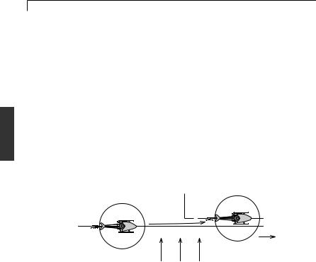
BEFORE USE
10
gyro controls the servo so that the movement of the tail stops, the same as a conventional gyro. At the same time, a sensor is controlled so that the tail is rotated in the opposite direction (returns to the original position). In short, the conventional gyro performs an operation known as "drifting stop", but the AVCS system performs an operation that "stops drifting and returns to original position". The "return to original position" operation added to the AVCS system improves rudder trim operation. In other words, the gyro can automatically trim the rudder against side winds. This also applies to reverse flight. When a helicopter is flying in the forward and reverse directions, the rudder trim is changed to advance, but with the AVCS system, this trim change is performed automatically and instantaneously so that the tail remains extremely stable even during high-speed reverse flight.
The AVCS system requires a high-precision angular velocity sensor. The GY501 realizes a high-precision angular velocity detection function and extremely small output drift by using a new type of gyro sensor. This minimizes rudder neutral position drift during flight and eliminates the need to trim the rudder during flight.
• The tail remains extremely stable.
Forward
Side wind
Differences in rudder control method
The following describes the differences between conventional gyro and AVCS gyro rudder control.
The conventional gyro sends the rudder control signals from the transmitter to the rudder servo and starts to move the tail. When the tail moves, the gyro detects this movement and generates a signal to stop it. If the tail continues to move even in this state, a rudder control signal larger than the signal from the gyro must be applied from the transmitter. That is, the difference between the rudder control signal from the transmitter and the control signal that attempts to stop this from the gyro becomes the actual amount of movement of the tail. Ordinarily, the rudder control signal is amplified
BEFORE USE
11
several times over by the gyro amp and is balanced with the gyro control signal so that the transmitter can be used at the normal steering angle.
The AVCS system uses a different rudder control method. As described in the preceding section, it has additional functions that "attempt to return movement by external force to the original position" and that generate an angular velocity proportional to the rudder control signal. That is, it functionally controls the speed of rotation of the tail. The original AVCS (Angular Vector Control System) came from this.
•In the AVCS mode, when the transmitter rudder stick is moved when the helicopter was stopped, the rudder servo controls operation until the tail reaches the specified rotational speed.
•Trim deviation of the rudder control signal also becomes a signal that causes the tail to turn so that even a little trim deviation causes the tail to move. Therefore, the rudder trim is made the same in all flight states and must match the neutral reference signal at the gyro. The method of reading the rudder neutral signal at the gyro will be described separately.
•Since the rudder mixing signals from the transmitter also become a tail rotation signal, all the rudder mixing functions must be disabled.
•In the AVCS mode, the gyro automatically trims the rudder so that linkage changes cannot be verified. Initially, the GY502 trims the rudder by flying in the Normal mode to take the rudder linkage neutral position. This centers the linkage. At this time, this rudder neutral reference point is read to the GY502.
Giving the gyro the rudder neutral reference signal and performing tail operation by referring to this signal in the AVCS mode in this way is how the AVCS system differs from the conventional system.
Digital Servo Compatibility
Gyro performance largely depends on the servo used. The GY502 displays top performance when used with a digital servo.
When using a digital servo, set the servo frame rate (Frm) function to High.
(For a description of the setting method, see page 19.)

DATA SETTING
12
DATA SETTING
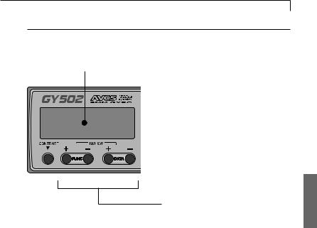
Name and Function of Each Part
GY502 control amp
LCDdisplay
Displays the set data. (8 characters X 1 line) |
(Input/outputerminals) |
|
|
|
Gyrosensorinput |
|
Rudderservooutput |
Edit keys
Used when setting data. Operated by pushing with the accessory mini screwdriver.
LCDcontrasttrimmer
(Receiverconnectors) Remote gain input Rudderinput
Allows adjustment of the contrast so that the LCD display is easiest to see.
It is adjusted with the accessory mini screwdriver.
GY502 gyro sensor
To control amp
Stick to the body using the accessory sensor tape.
DATA SETTING
13
LCD Display and Edit Keys
LCD display
Set data display and operation status monitoring are possible.
Edit keys
Setup screen call
The setup screens can be sequentially called with the FUNC+ or FUNCkey. For the order in which the setup screens are called, see the function map.
Data setting
Perform data setting with the DATA+ or DATAkey. When setting a value, the data is increased when the
DATA+ key is pressed and is decreased when the DATAkey is pressed. The mode can also be selected using either the DATA+ or the DATAkey.
 Loading...