


 Loading...
R
Thank you for purchasing the Futaba 3PJ SUPER.
Prior to operating your 3PJ SUPER, please read this manual thoroughly and use your system in a safe manner.
After reading this manual store it in a safe place.
See the glossary on page (P108-109) for the definition’s of the special terms used in this manual.
Application, Export and Reconstruction
1. Use this product in surface models only.
The product described in this manual is subject to regulations of the Ministry of Radio/Telecommunications and is restricted under Japanese law to such purposes.
2.Exportation Precautions
(a)When this product is exported from Japan, its use is to be approved by the Radio Law of the country of the destination.
(b)Use of this product with other than models may be restricted by Export and Trade Control Regulations. An application for export approval must be submitted.
3.Modification, adjustment and replacement of parts.
Futaba is not responsible for unauthorized modification, adjustment and replacement of parts of this product.
THE FOLLOWING STATEMENT APPLIES TO THE RECEIVER (FOR U.S.A.)
This device complies with part 15 of the FCC rules. Operation is subject to the following two conditions.
(1)This devise may not cause harmful interference, and
(2)This devise must accept any interference received, including interference that may cause undesired operation.
2

THE RBRCTM SEAL (FOR U.S.A.)
The RBRCTM SEAL on the (easily removable) nickel-cadmium battery contained in Futaba products indicates that Futaba Corporation of America is voluntarily participating in an industry program to collect and recycle these batteries at the end of their useful lives, when taken out of service within the United States. The RBRCTM program provides a convenient alternative to placing used nickel-cadmium batteries into the trash or municipal waste which is illegal in some areas.
Futaba Corporation of America's payments to RBRCTM makes it easy for you to return the spent battery to Futaba for recycling purposes. You may also contact your local recycling center for information on where to return the spent battery. Please call 1-800-8-BATTERY for information on Ni-Cd battery recycling in your area. Futaba Corporation of America's involvement in this program is part of its commitment to protecting our environment and conserving natural resources.
RBRCTM is a trademark of the Rechargeable Battery Recycling Corporation.
-No part of this manual may be reproduced in any form without prior permission. -The contents of this manual are subject to change without prior notice.
-This manual has been carefully written, please write to Futaba if you feel that any corrections or clarifications should be made.
-Futaba is not responsible for the use of this product.
3

Table Of Contents
For Your Safety As Well As That Of Others |
........... 6 |
Explanation of Symbols ................................................................................ |
6 |
Operation Precautions .................................................................................. |
7 |
Nicad Battery Handling Precautions ........................................................... |
9 |
Storage and Disposal Precautions ............................................................ |
10 |
Other Precautions ....................................................................................... |
11 |
Before Using ........................................................... |
12 |
Features ........................................................................................................ |
12 |
Set Contents ................................................................................................ |
14 |
Nomenclature ............................................................................................... |
15 |
Installation .............................................................. |
27 |
Receiver and Servo Connections .............................................................. |
27 |
Installation Safety Precautions .................................................................. |
28 |
Initial Set-Up ........................................................... |
29 |
Preparations (Transmitter) ......................................................................... |
29 |
Direct Mode Functions .......................................... |
32 |
Function Map ............................................................................................... |
32 |
Steering ATV ................................................................................................ |
33 |
Throttle ATV ................................................................................................. |
35 |
Channel 3 ATV ............................................................................................. |
37 |
Steering EXP ................................................................................................ |
39 |
Throttle EXP/EXP2/CRV .............................................................................. |
40 |
Model Select ................................................................................................. |
44 |
Custom Key .................................................................................................. |
45 |
Select Mode Functions .......................................... |
46 |
Function Map ............................................................................................... |
46 |
Subtrim ......................................................................................................... |
47 |
4

Steering Speed .................................................................................. |
49 |
A.B.S. Function .................................................................................. |
51 |
Idle-Up ................................................................................................ |
55 |
Throttle Acceleration ........................................................................ |
56 |
Start Function .................................................................................... |
58 |
Traction Control ................................................................................ |
61 |
Step ..................................................................................................... |
63 |
Timer ................................................................................................... |
64 |
Model Name ....................................................................................... |
74 |
Setup Mode Functions .................................... |
75 |
Function Map ..................................................................................... |
75 |
Dual Rate/Second Dual Rate ............................................................ |
76 |
ATL Function ..................................................................................... |
78 |
Channel 3 Position ............................................................................ |
79 |
Throttle Neutral .................................................................................. |
80 |
Programmable Mixing 1/2 ................................................................. |
81 |
Tilt Mixing ........................................................................................... |
85 |
Reverse Switch .................................................................................. |
87 |
Function Select Trim ......................................................................... |
88 |
Function Select Switch ..................................................................... |
89 |
Fail Safe (PCM Mode Only) ............................................................... |
91 |
Battery Fail Safe (PCM Mode Only) ................................................. |
92 |
PCM/PPM Select ................................................................................ |
93 |
LCD Contrast Adjustment ................................................................ |
94 |
Audible Alarm Tone .......................................................................... |
95 |
Model Reset ....................................................................................... |
96 |
Model Copy ........................................................................................ |
97 |
Throttle Curve Selection ................................................................... |
98 |
Rate Display Selection ...................................................................... |
99 |
Reference ....................................................... |
100 |
Ratings ............................................................................................. |
100 |
Optional Parts .................................................................................. |
101 |
Troubleshooting .............................................................................. |
104 |
Error Displays .................................................................................. |
105 |
When requesting repair (For U.S.A.) ............................................. |
107 |
Glossary ........................................................................................... |
108 |
Glossary (LCD Display) .................................................................. |
109 |
3PJ SUPER Data Sheet ................................................................... |
110 |
Throttle Curve .................................................................................. |
111 |
For Your Safety
As Well As
That Of Others
Before
Using
Installation
Initial
Set-Up
Direct Mode
Functions
Select Mode
Functions
Setup Mode
Functions
Reference
5

Others Of That As Well As Safety Your For
For Your Safety As Well As That Of Others
Usethisproductinasafemanner.Pleaseobservethefollowingsafetyprecautionsat alltimes.
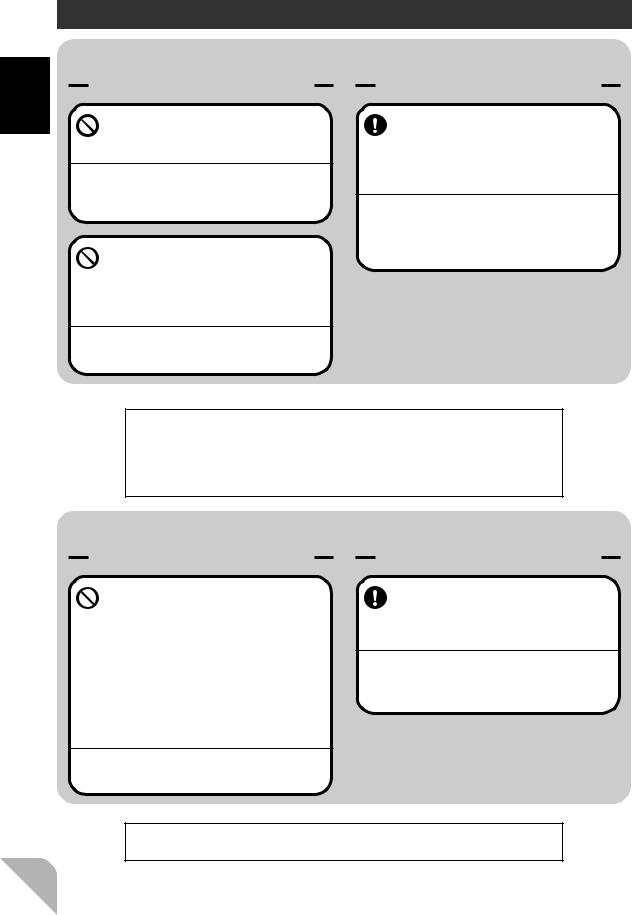
Explanation of Symbols
Thepartsofthismanualindicatedbythefollowingsymbolsareextremelyimportant andmustbeobserved.
Symbols |
Explanation |
Indicates a procedure which could lead to a dangerous situ-
Danger ation and may cause death or serious injury if ignored and not performed properly.
Indicates procedures which may lead to dangerous situa- Warning tions and could cause death or serious injury as well as su-
perficial injury and physical damage.
Caution |
Indicates procedures that may not cause serious injury, but |
could lead to physical damage. |
Symbols:  ; Prohibited
  ; Mandatory
6

Operation Precautions
 Warning
Prohibited Procedures
Do not operate two or more models on the same frequency at the same time.
Operating two or more models at same time on the same frequency will cause interference and loss of control of both models.
AM, FM (PPM) and PCM are different methods of modulation. Nonetheless the same frequency can not be used at the same point in time, regardless of the signal format.
Do not operate outdoors on rainy days , run through puddles of water or when visibility is limited.
Should any type of moisture (water or snow) enter any compoent of the system, erratic opreation and loss of control may occur.
Do not operate in the following places.
-Near other sites where other radio control activity may occur.
-Near people or roads.
-On any pond when rowboats are present.
-Near high tension power lines or communication broadcasting antennas.
Interference could cause loss of control . Improper installation of your Radio Control System in your model could result in serious injury.
Do not operate this R/C system when you are tired, not feeling well or under the influence of alcohol or drugs.
Your judgment is impaired and could result in a dangerous situation that may cause serious injury to yourself as well as others.
Mandatory Procedures
Extend the transmitter antenna to its full length.
If the transmitter antenna is not fully extended the operating range of the radio will be reduced.
Always perform a operating range check prior to use.
Problems with the radio control system as well as improper installation in a model could cause loss of control.
(Simple range test method)
Have a friend hold the model, or clamp it down or place it where the wheels or prop can not come in contact with any object. Walk away and check to see if the servos follow the movement of the controls on the transmitter. Should you notice any abnormal operation, Do not operate the model. Also check to be sure the model memory matches the model in use.
Check the transmitter antenna to be sure it is not loose.
If the transmitter antenna works loose, or is disconnected while the model is running signal transmission will be lost. This will cause you to lose control of the model..
For Your Safety As Well As That Of Others
7

Others Of That As Well As Safety Your For
 Caution
Prohibited Procedures
Do not touch the engine, motor, speed control or any part of the model that will generate heat while the model is operating or immediately after its use.
These parts may be very hot and can cause serious burns.
Mandatory Procedures
Turning on the power switches. |
When making adjustments to |
||
Always check the throttle trigger on the |
the model do so with the en- |
||
transmitter to be sure it is at the neutral |
gine not running or the motor |
||
position. |
disconnected. |
||
|
|
|
|
1. Turn on the transmitter power switch. |
You may unexpectedly lose control and |
||
2. Turn on the receiver or speed control |
create a dangerous situation. |
||
|
|||
power switch. |
|
|
|
|
|
||
Turning off the power switches |
FM |
|
FP-R113F |
Always be sure the engine is not |
|
running or the motor is stopped. |
|
1.Turn off the receiver or speed control power switch.
2.Then turn off the transmitter power switch.
If the power switches are turned off in the opposite order the model may unexpectedly run out of control and cause a very dangerous situation.
When operating your model always display a frequency flag on your transmitter antenna.
When adjusting the transmitter on land while preparing to run (cruise), take measures so that the wind will not knock over the transmitter.
If the transmitter is knocked over, the throttle stick may be accidentally set to the operating position and you may lose control.
(Failsafefunction)
Before running (cruising), check the fail safe function.
Check Method;
Before starting the engine, check the fail safe function as follows:
1)Turn on the transmitter and receiver power switches.
2)Wait at least one minute, then turn off the transmitter power switch. (The transmitter automatically transfers the fail safe data to the receiver every minute.)
3)Check if the fail safe function moves the servos to the preset position when reception fails.
The fail safe function is a safety feature that minimizes set damage by moving the servos to a preset position when reception fails. However, if set to a dangerous position, it has the opposite effect. When the reverse function was used to change the operating direction of a servo, the fail safe function must be reset.
Setting example: Throttle idle or brake position
8

Nicad Battery Handling Precautions
(OnlywhenNicadbatteriesareused)
 Warning
Mandatory Procedures
Always check to be sure your batteries have been charged prior to operating the model.
Should the battery go dead while the model is operating loss of control will occur and create a very dangerous situation.
When the model is not being used, always remove or disconnect the Nicad battery .
Should the battery be left connected this could create a dangerous situation if someone accidentally turns on the receiver power switch. Loss of control would occur.
To recharge the transmitter Nicad , use the special charger made for this purpose.
Overcharging could cause the Nicad battery to overheat, leak or explode. This may lead to fire, burns, loss of sight and many other type's of injuries.
Special
 Charger
Caution
Prohibited Items
Do not use commercial AA size Nicad batteries. 
Quick charging may cause the battery contacts to overheat and damage the battery holder.
Do not short circuit the Nicad battery terminals.
Causing a short circuit across the battery terminals may cause abnormal heating, fire and burns.
Do not drop the Nicad battery or expose it to strong shocks or vibrations.
The battery may short circuit and overheat, electrolyte may leak out and cause burns or chemical damage.
Shock
Prohibited
For Your Safety As Well As That Of Others
9
Others Of That As Well As Safety Your For
Storage and Disposal Precautions
 Warning
Prohibited Procedures Mandatory Procedures
Do not leave the radio system or models within the reach of small children.
A small child may accidentally operate the system, this could cause a dangerous situation and injuries. Nicad batteries can be very dangerous when mishandled and cause chemical damage.
Do not throw Nicad batteries into a fire. Do not expose Nicad batteries to extreme heat. Also do not disassemble or modify a Nicad battery pack.
Overheating and breakage will cause the electrolyte to leak from the cells and cause skin burns, loss of sight as well as other injuries.
When the system will not be used for any length of time store the system with batteries in a discharged state. Be sure to recharge the batteries prior to the next time the system is used.
If the batteries are repeatedly recharged in a slightly discharged state the memory effect of the nicad battery may considerably reduce the capacity . A reduction in operating time will occur even when the batteries are charged for the recommended time.
<Nicad Battery Electrolyte>
The electrolyte in Nicad batteries is a strong alkali. Should you get even the smallest amount of the electrolyte in your eyes, DO NOT RUB, wash immediately with water, seek medical attention at once. The electrolyte can cause blindness. If electrolyte comes in contact with your skin or clothes, wash with water immediately.
 Caution
Prohibited Procedures Mandatory Procedure
Do not store your R/C system in the following places.
-Where it is extremely hot or cold.
-Where the system will be exposed to direct sunlight.
-Where the humidity is high.
-Where vibration is prevalent.
-Where dust is prevalent.
-Where the system would be exposed to steam and condensation.
Storing your R/C system under adverse conditions could cause deformation and numerous problems with opreation.
If the system will not be used for a long period of time remove the batteries from the transmitter and model and store in a cool dry place.
If the batteries are left in the transmitter electrolyte may leak and damage the transmitter. This applies to the model also, remove the batteries from it also to prevent damage.
<Nicad Battery Recycling>
A used Nicad battery is valuable resource. Insulate the battery terminals and dispose the battery by taking it to a battery recycling center.
10
Other Precautions
 Caution
Prohibited Procedures
Do not expose plastic parts to fuel, motor spray, waste oil or exhaust.
The fuel, motor spray, waste oil and exhaust will penetrate and damage the plastic.
Mandatory Procedures
Always use only genuine Futaba transmitters, receivers, servos, FET a m p s ( e l e c t r o n i c s p e e d controls),Nicad batteries and other optional accessories.
Futaba will not be responsible for problems caused by the use of other than Futaba genuine parts. Use the parts specified in the instruction manual and catalog.
For Your Safety As Well As That Of Others
11

Before Using
Using Before
Features
- Eight Model Memories/Eight More Models Can Be Added By Using the Data Pac
EnglishandJapaneseKatakanacharactersmaybeusedtoassigneachmodelaname. Modelmemorieswithslightlydifferentsettingscanbeeasilycreatedbyusingthe modelcopyfunction.Also,eightmoremodelscanbeaddedbyusingtheoptional DataPac(DP-16K).
- Large LCD display
Constantlydisplaysalltheinformationneededformonitoring.Thelargecharacters canbeeasilyreadwhenmakingadjustments.
- Three Function Selection Modes
Newmenuconfigurationallowsdirectaccesstothemostfrequentlyusedfunctions. (DirectMode/SelectMode/Set-UpMode)
- Second Dual Rate (D/R2)
Letsyouchangethesteeringanglewithonetouchwhilerunning.
- Anti-Skid Brake System (A. B. S. Function)(A.B.S.)
Allowsbrakingwithoutthetireslosingtheirgriponthetrackevenwhenbrakinggas poweredcarsoncorners.
- Throttle Acceleration (TH.ACC)
Gaspoweredcarshavealagtimebeforetheclutchisengagedorthebrakesare applied.Thisfunctionminimizesthislagtime.
- Traction Control (TRAC)
Whentriggeroperationisperformedsuddenlyonslicksurfaces,thewheelsmerely spinandthecardoesnotacceleratesmoothly.BysettingtheTractionControlfunction,operationcanbeperformedsmoothlyandpleasantlyandbatteryconsumption canbereduced.
- Start (START)
Onaslicksurface,ifthethrottletriggerissettofullthrottleatthestartofarace,the
wheelswillspinandthecarwillnotacceleratesmoothly.WhentheStartfunctionis set,merelypullingthethrottletriggerforwardcausesthethrottleservotoautomaticallymovetoapresetpositionandthecartoacceleratesmoothly.
- Steering Speed (ST.SPD)
Allowsyoutoadjustthesteeringservospeedtomatchyourstyleofdriving.
12

- Advanced Timer (TIMER)
Theracingtimer(laptimer)canrecordthetotaltimeandupto99laps.Thetimercan
beautomaticallyactivatedbytriggeroperation.Analarmcanbesetfrom30second
beforetimeisup.
ANavigationtimerthatiseffectiveinpracticerunscanalertyoutothetargetlap.
- Digital Trim w/Reset Function
ThetrimpositionisconstantlydisplayedontheLCDscreen.One-stepservotravel canalsobeadjusted. Steeringandthrottletrimadjustmentshavenoeffectonthemaximumservotravel.
- Trim Function Selection
Allowsyoutoassignvariousfunctionstothetrimmers(digitaltrim,gripdial,knob).
Allthetrimsaredigital,sotheydonothavetoberepositionedforeachmodel.
- Switch Function Selection
Allowsyoutoassignvariousfunctionstothetwoswitches.
-Left Hand Reversible
-Black Transmitter Antenna
-New Light Weight Design and Extraordinary Balance
-Tension Adjustment
Steeringwheelspringtensioncanbeadjustedfromtheoutside.
- Trigger Stop Function (Mechanical ATL)
ThemechanicaltriggerstopcanbeusedasATL.
- Display Switch
Functionscanbesetwithouttransmittingasignal.
-Body Rest (Option)
-Receiver w/DSC Function (Connection Cord is Optional)
FM:R113F,PCM:R113iP
Before Using
13
Using Before
Set Contents
Afteropeningthebox,firstcheckifthecontentsconformtothefollowing.Thecontentsdependonthesetasshownbelow.
Transmitter |
T3PJ SUPER |
|
|
|
|
RF module |
TJ-FM |
|
*Installed in transmitter. |
||
|
||
|
|
|
Receiver |
R113F(FM) or R113iP(PCM) |
|
|
|
|
Servo |
S9402, S9304 or (none) |
|
|
|
|
|
Transmitter Ni-cad battery pack NT8F700B |
|
Miscellaneous |
or Battery box |
|
*Installed in transmitter. |
||
|
Receiver switch |
|
|
Instruction manual |
-Ifanyofthesetcontentsaremissing,oryouhaveanyquestions,pleasecontactyou dealer.
 Caution
Always use only genuine Futaba transmitter, receiver, FET amp, Ni-cad battery and other optional parts.
Futaba will not be responsible for damage caused by other than genuine Futaba parts and components. Use only the genuine Futaba parts and components listed in the instruction manual and catalog.
14

Nomenclature
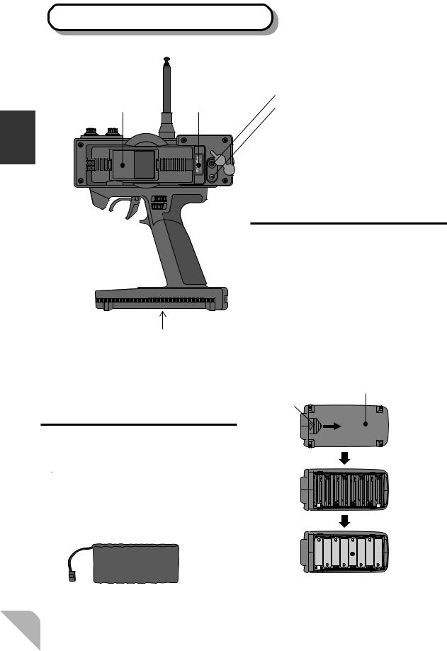
Transmitter T3PJ SUPER (Front)
Antenna
(See page 16 for the operating instructions.)
Throttle trim (DT2)
Pilot lamp
LCD screen |
PILOT |
Power |
|
switch |
|
|
MULTI FUNCTION DISPLAY |
(See page 16 for the |
|
operating instructions.) |
(GD1) |
|
Steering dual rate dial
ATL dial (GD2)
(See page 16 for the operating instructions.)
(See page 16 for the operating instructions.)
Steering trim (DT1)
|
Steering wheel |
|
||
|
Traction control switch |
|
||
|
|
(SLD) |
|
|
|
|
|
CH3 knob (KNOB) |
Using |
|
|
|
Edit keys |
|
|
|
|
|
|
DIRECT |
ST.EXP |
M.SEL |
|
Before |
|
UP |
+ |
|
|
|
SETUP |
RESET |
(See page 17 for the |
|
SELECT |
DOWN |
- |
|
|
TH.EXP |
ATV |
CUSTOM |
|
|
adjustment instructions.)
Mechanical ATL
 adjusting screw
(See page 16 for the operating
instructions.)
Digital trim 3 (DT3)
Wheel tension
adjusting screw (See page 17.)
Throttle trigger Timer switch (PSH)
Grip Handle
3PJ SUPER DIGITAL PROPORTIONAL RADIO CONTROL SYSTEM
*Theswitches,knobs,andtrimmersinthefigureareshownintheinitialsettingposition.
Precautions when turning the power switch on and off.
Whenthedatawaschangedusingtheeditkeysortrimlevers,waitatleasttwosecondsbeforeturningoffthepower.Ifthepoweristurnedoffwithintwosecondsafter thedatawaschanged,thenewdatawillnotbewrittentomemory.
15
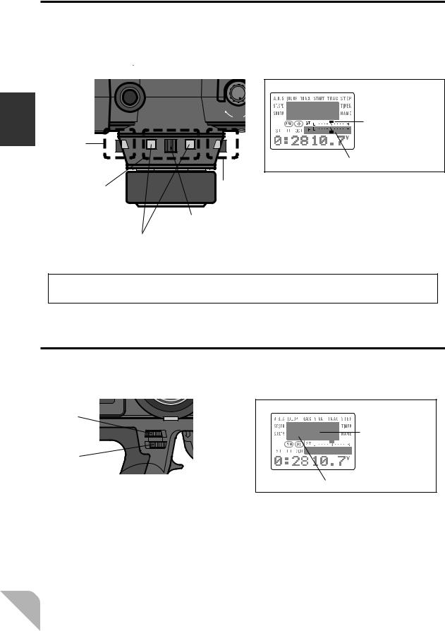
Digital Trim Operation
(Initial settings: DT1: Steering trim, DT2: Throttle trim, DT3: ------- |
) |
Operatingbythelever:Pushthelevertotheleftorright(upordown). Operatingbypushbuttonswitch:Pressthepushbuttonswitchinthedesireddirection.
ThecurrentpositionisdisplayedontheLCDscreen.
Using Before
ON
SLD
Steering trim display
DT2
DT.1
Throttle trim display
|
|
|
|
|
DT3 |
|
DT1 |
- Each step is indicated by a tone. |
|||||
|
|
|
|
|
|
- When the trim exceeds the maximum trim adjustment |
|
|
|
|
|
|
range, the tone will change pitch and the lever will not |
|
|
|
Lever |
|
move any farther. |
|
|
|
|
|
|
|
- Return to the neutral position (center) by pressing both |
|
Push button switch |
|
the push button switches simultaneously for about one |
|||
|
|
|
|
|
|
second. |
Trim Operation
Withthecentertrimfeature,trimadjustmentshavenoeffectonthemaximumservo travel.Thispreventsthelinkagesfrombindingwhenadjustmentsaremade.
Grip dial operation
(Initial settings: GD1=Steering D/R, GD2=ATL)
Operatethedialsbyturningthem.ThecurrentsetvalueisdisplayedontheLCD
screen.
GD1
ATL display
GD2
Steering D/R display
- A click sound is made at each step.
- When the maximum position is reached at each side, the tone of the click changes. Thereafter, the set value does not change.
16

Wheel Tension Adjustment
Makethisadjustmentwhenyouwanttochangethesteeringwheelspringtension.
Adjustment
Turn the screw inside the adjusting hole using a 1.5mm hex wrench.
- Turning the adjusting screw clockwise, increases the spring tension.
DIRECT
SELECT
TH.EXP
Caution
Ifturnedtoofarcounterclockwise,theadjustingscrewmayfallout.
Tension adjusting screw
Before Using
Mechanical ATL Adjustment
Makethisadjustmentwhenyouwanttomakethethrottletriggerbrake(back)side
strokenarrower.
Adjustment
Using a Phillips screwdriver, adjust the trigger brake (back) side stroke by turning the screw through the adjusting hole indicated by the arrow in the figure. (The screw moves the throttle trigger stopper.)
- When the adjusting screw is turned clockwise, the stroke becomes narrower.
|
SETUP |
RESET |
SELECT |
DOWN |
- |
TH.EXP |
ATV |
CUSTOM |
Mechanical ATL
adjusting screw
Caution
Whenthestrokewasadjusted,thethrottleservotravelmustbeadjustedbydatasetting.
17
Transmitter T3PJ SUPER (Rear)
Using Before
|
(See page 20 for the |
|
(See page 20 for the |
handling instructions.) |
Charging jack |
handling instructions.) |
DP-16K |
|
RF module |
Data Pac |
DSC jack |
|
|
|
|
|
(See page 103 for the handling instructions.) |
|
|
(The DSC cord sold separately is necessary.) |
CHG
DSC
Battery cover
- When changing the Ni-cad battery pack, or dry cell batteries, remove this cover.
Ni-cad Battery
Replacement
(For Ni-cad battery system)
TheNi-cadbatteryisconnectedbya connectorsothatitcanberemoved whenyouwillnotbeusingthetransmitterforalongtime,orwhenreplacingadeadbatterywithasparebattery.
- Always use an NT8F700B Ni-cad battery.
Dry cell Battery
Replacement
(For dry cell battery system)
1.Slide the transmitter battery cover in the arrow direction while pressing the part shown in the figure.
2.Load the eight batteries in accordance with the polarity markings on the battery holder.
3.Slide the battery cover back onto the transmitter.
While pressing |
Battery cover |
this part. |
|
|
|
|
|
|
|
|
|
|
|
|
|
|
|
|
|
|
|
|
|
|
|
|
|
|
|
|
|
|
|
|
|
|
|
|
|
|
|
|
|
|
|
|
|
|
|
|
|
|
|
|
|
|
|
|
|
|
|
|
|
|
|
|
|
|
|
|
|
|
|
|
|
|
|
|
|
|
|
|
|
|
|
|
|
|
|
|
|
|
|
Ni-cad battery |
|
|
|
|
|
|
|
|
|
|
|
|
|
|
|||
|
|
|
|
|
Dry cell battery (x8) |
||||||||||||
NT8F700B |
|
|
|
|
|
||||||||||||
|
|
|
|
|
|
|
|
|
|
|
|
|
|
||||
18

Charging the Ni-cad Battery
Charging
1.Plug the transmitter cord of the special charger into the charging jack on the rear of the transmitter.
2.Plug the charger into an AC outlet.
3.Check that the charging LED lights.
AC outlet
Charger
Transmitter charging
LED
Cord to transmitter charging jack
WhenchargingtheNT8F700BNi-cadbatterywiththespecialcharger,allowabout 15hoursforcharging.Ifthetransmitterhasnotbeenusedforsometime,cyclethe batterybycharginganddischargingittwoorthreetimes.
Diode Protection
Thetransmitterchargingcircuitisequippedwitha1.5Adiodetopreventshortcircuits.Ifthebatteryischargedwithaquickchargerforotherthandigitalproportional R/Csets,itmaynotbefullychargedandthecircuitsinsidethetransmittermaybe damaged.
Before Using
 Warning
Never plug it into an outlet other than indicated voltage.
Do not insert and remove the charger when you hands are wet.
Plugging the charger into the wrong outlet may re- |
It may cause an electric shock. |
sult in an explosion, sparking, or fire. |
|
Always use the special charger or a quick charger for digital proportional R/C sets to charge a digital proportional R/C set Ni-cad battery.
Overcharging a Ni-cad battery can result in burns, fire, injuries, or loss of sight due to overheating, breakage, or electrolyte leakage.
Use the special charger.
 Caution
Never try to recharge a dry cell battery.
The transmitter may be damaged or the battery electrolyte may leak or the battery may break.
When the charger is not in use, disconnect it from the AC outlet.
Do this to prevent accidents and to avoid overheating.
19

Using Before
RF Module
Removal
1.Pull the RF module forward while pressing the tabs at the left and right inward.
Insertion
1.Insert the RF module while being careful not to bend the transmitter side connector pins.
2.Insert the RF module until the tabs at the left and right snap in place with a “click”.
RF Module Temperature Rise
RF module
Tabs
ThetemperatureoftheRFmodulewillriseslightlyduringoperation.
Handling the Data Pack
Thesetdatafor8unitscanbestoredinthe3PJSUPERtransmitterbodyandtheset datafor8moreunitscanbestoredinaDP-16K(Option)removabledatapack.
Data pack DP-16K (Option)
CHG
DSC
Data pack insertion slot
-Graspthedustproofcapandinsert thedatapackfully.
Inserting and removing the data pack
Alwaysturnoffthetransmitterpowerbeforeremovingandinsertingthedatapack.
Data pack initialization
Whenthedatapackisusedandthepoweristurnedonforthefirsttime,thedatapack mustbeinitializedbeforeitcanbeusedwiththistransmitter.When"CAM-INI?"is displayedonthescreenafterthepoweristurnedon,pressthe"+"key.Thisautomaticallyinitializesthedatapack.Thisoperationisunnecessarythereafter.
20
3PJ SUPER and 3VC transmitter data pack compabilitily
-Notethatthedigitaltrim3(DT3)andslideswitch(SLD)initializationvaluesare different. -The3VCtransmitterdoesnothaveadigitaltrimfunctionreversefunction.There- fore,whenthe3PJSUPERtransmittercopieddatatoa3VCtransmitter,the3VC ignoresthecopieddata.However,sincethedataisstoredasis,whenthedataisrecopiedtothe3PJSUPERtransmitter,the3PJSUPERwilloperateusingtheoriginal settings.
Set data backup
Thesetdataofeachfunction(transmitterbodyanddatapack)ofthe3PJSUPER
transmitterisstoredinamemoryelementthatdoesnotrequireabackupbattery.
Therefore,the3PJSUPERtransmittercanbeusedwithoutpayingattentiontothe
backupbatterylife.
Adaptation For Left-Hand Use
Thistransmittercanbemodifiedforleft-handuse.
1. Remove the Transmitter Battery. Carefully remove the 5 screws from the rear case cover. Do not use excessive force to get the case apart.
2. Carefully remove the 2 gold screws and |
1 |
|
black screw at the top of the handle. Be very |
CHG |
|
careful the Display switch cover will fall out. |
|
DSC |
|
|
|
3. Rotate the handle and reinstall the screws in same position as they were removed. Make sure you do not pinch or put excessive pressure no any wires. Do not overtighten the screws.
4. Place the Display switch cover in position and reinstall the rear case cover. Again be careful and do not overtighten the screws.
Before Using
21
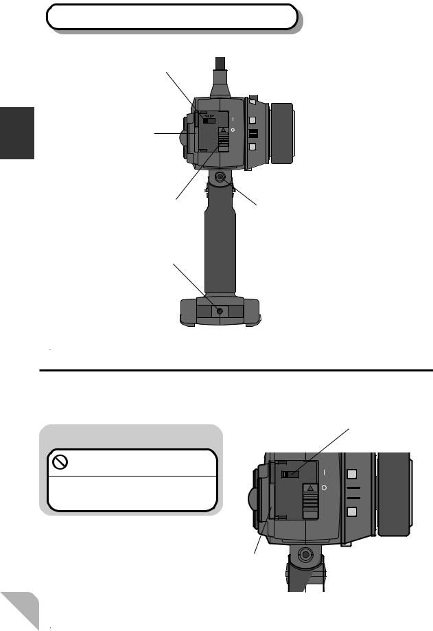
Transmitter T3PJ SUPER (Side View)
Using Before
Display switch
OFF |
ON |
|
|
|
POWER |
DISPLAY |
ON |
|
|
SW |
|
Cover |
DT.2 |
Power switch
Body rest mounting hole
Sound port
- Use a commercial earphone.
(Use a radio earphone with a 3.5mm diameter plug.)
- When the surroundings are noisy during races, etc., you can listen to the alarm tone using an earphone.
The alarm tone can also be heard from the transmitter.
Display Switch
IftheDisplaySwitchisturnedonwithoutturningonthepowerswitch,thetransmit-
terdatacanbesetwithouttransmittingasignal.
 Warning
Never turn on the power switch while using this function.
If the power switch is turned on, a signal will be transmitted and will interfere with other models operating on the same frequency.
Display Switch
OFF 

 ON
ON
OFF
 ON
ON
|
POWER |
DISPLAY |
ON |
SW |
|

 DT.2
DT.2
Cover
22
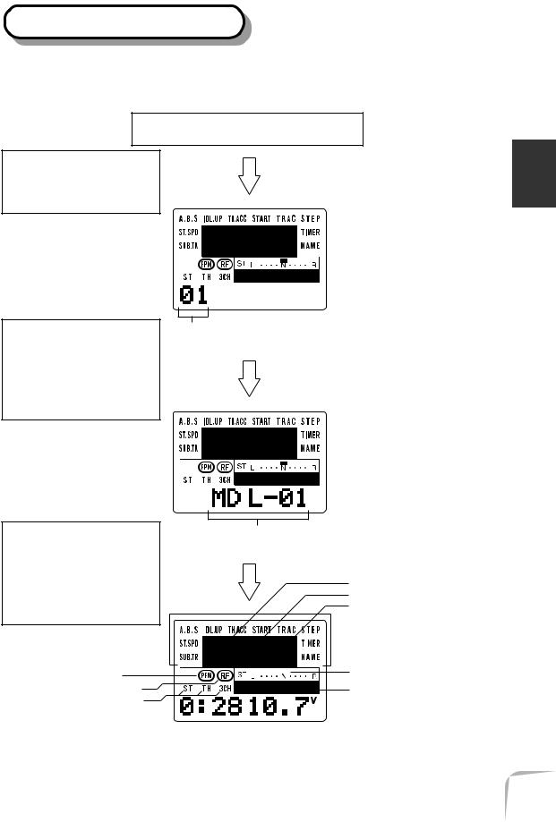
LCD Screen and Edit Keys
Whenthetransmitterpowerswitchisturnedon,themodelmemoryNo.andmodel namecurrentlycalledaretemporarilydisplayedforconfirmation.
Turn on the power switch
A tone will sound to show that the power is on.
After the model No. is displayedforaboutone second, the LCD will switch to the model namedisplay.
Afterthemodelnameis displayed for several seconds, the LCD will switchtothetimerand voltagedisplay.
Before Using
Model No. (1~8)
Model name (6 characters)
D/R function rate display
ATL function rate display
Channel 3 position display
|
|
|
|
|
|
Select mode menu |
|
||||||
|
|
|
|
|
|
|
PCM/PPM display |
|
|
|
|
|
Steering trim display |
|
|
|
||||
RF output monitor |
|
|
|
|
|
Throttle trim display |
|
|
|
Channel selection display |
|
|
|
|
||
|
|
|
|
|
|
|
|
|
|
|
|
|
|
|
|
|
|
|
|
|
Total time display |
|
Battery voltage display |
||||
(Hours : Minutes) |
|
|
|
|
||
23

SET-UP Mode Function SelectionSELECT Mode Function Selection
To call the function set-up screen in the SET-UP mode, press the UP and DOWN keys simultaneously.
After that, select the function with the UP or DOWN key.
To end the SET-UP mode, press the UP and DOWN keys simultaneously again, or press the DIRECT key twice.
To call the function set-up screen in the SELECT mode, press the UP or DOWN key at the initial screen.
After that, select the function with the UP or down
KEY.
To end the SELECT mode, return to the initial screen by pressing the UP or DOWN key similarly, or press the DIRECT key twice.
Using Before
|
DIRECT |
ST.EXP |
M.SEL |
Edit keys |
TH.EXP |
UP |
+ |
ATV |
CUSTOM |
||
|
|
SETUP |
RESET |
|
SELECT |
DOWN |
- |
DIRECT Mode Function SelectionData Entry Keys
To call the function set-up screen in the DIRECT mode, first press the DIRECT key, then select the function by pressing the key corresponding to the function desired as shown below.
-Steering EXP key (ST.EXP)
-Model select key (M.SEL)
-Throttle EXP key (TH.EXP)
-ATV key (ATV)
-Custom key (CUSTOM)
To end the DIRECT mode, press the DIRECT key twice.
Use the SELECT key to select the set-up item and channel at the function set-up screen.
Use the + and - keys to enter data. To reset (return to initial value) the entered data, press the + and - keys simultaneously.
Switch screen display
Forfunctionsthatcanusethepush-buttonswitch(PSH)orslideswitch(SLD),the followingsymbolsaredisplayedonthesetupscreenoftherelaventfunction.
(A.B.S.functionexample)
*For the A.B.S function, both switches can be set.
[If this is displayed, SLD can be set]
[If this is displayed, PSH can be set]
Whenthescreenswitchdisplayisenlargedas shownattheright,thatswitchcanbeset.
 [Display is enlarged]
24

LCD Screen Contrast
TheLCDscreencontrastcanbeadjusted.(Formoreinformation,seepage94.)
Caution
DonotadjustthecontrastsothattheLCDistoobrightortoodark.
Whenthedisplaycannotbereadduetoatemperaturechange,datacannotbeset.
LCD Screen Temperature Change
Inthefollowingcases,theLCDmaybecomedifficulttoreadduetoatemperature
change.
-On hot summer days and cold winter days, the LCD may be easy to read indoors, but difficult to read outdoors.
-If the contrast is too bright or too dark, temperature changes and lighting conditions may cause the screen to become difficult to read.
Contrast Adjustment
1Turn on the transmitter power.
2Press the DIRECT key twice.
3Press the UP and DOWN keys simultaneously.
4Press the DOWN key six times.
5If the screen is too dark, adjust the screen to the point where it can be easily read. If the screen is too dark, press the - key. If the screen is too bright, press the + key.
Before Using
Total Timer
Thetotaltimershowsthetotaltimefromthelasttimeitwasreset.
Reset
1At the total time display, press the + and - keys simultaneously for about one second.
DIRECT |
ST.EXP |
M.SEL |
|
UP |
+ |
|
SETUP |
RESET |
SELECT |
DOWN |
- |
TH.EXP |
ATV |
CUSTOM |
25

Using Before
Receiver R113F/R113iP
Crystal
Antenna
FP-R113F
FM
1
2
3
B/C
R113F/R113iP
receiver
When changing the frequency, use the specified Futaba crystal set.
Connectors
1:Steering servo (CH1)
2:Throttle servo (CH2)
3:CH3 servo (CH3)
B/C: Power connector/DSC connector
Forthereceiver,servos,andotherconnections,seepage27.FortheDSCcord(option)connections,seepage103.
Servo S9402 / S9304
Servo horn
Mounting flange
to Receiver 

<Accessory>
Thefollowingitemsareprovidedforsetting: -Spareservohorn -Partsforservoinstallation (Fortheinstallationprecautions,seepage28.)
26

Installation
Receiver and Servo Connections
Whenconnectingandinstallingthereceiverandservos,readthe“InstallationSafety
Precautions”onthenextpage.
Installation When An FET Amp Is Used (MC510CFET Amp)
FET amp |
|
|
|
|
|
Ni-cad battery |
|
|
- |
|
|
Steering servo |
|
Installation |
|
CH1 |
+ |
||
Motor |
|||
|
|||
1 |
|
|
|
2 |
|
|
|
3 |
|
|
|
B/C |
|
|
|
Receiver CH2 |
|
|
|
CH3 |
|
|
Installation For Gas Powered Models
|
|
CH1 |
Steering servo |
|
|
|
|
||
|
|
CH2 |
|
|
|
1 |
|
Throttle servo |
|
|
2 |
|
||
|
3 |
|
||
|
B/C |
|
||
Receiver |
CH3 |
|
||
|
|
B |
Channel 3 servo |
|
To receiver Receiver |
||||
|
||||
battery |
switch |
|
||
27

Installation
Installation Safety Precautions
 Warning
Connector Connections Electronic speed control
Be sure the receiver, servo, crystal and connectors are fully and firmly connected.
If vibration from the model cause a connector to work loose while the model is in operation. You may lose control .
Receiver Vibration Damping and Waterproofing
(Car)
Dampen the vibration to the receiver
by mounting to the chassis or mounting plate with thick double sided tape in electric powered models. In gas powered models wrap the receiver in foam and mount it where the vibration is the least prevalent.
(Boat)
Dampen the vibration to the receiver by wrapping it in foam. Waterproof by placing it in plastic bag or watertight radio box in model.
If the receiver is subjected to strong vibration or shock erratic or loss of control may occur. If any moisture comes in contact the receiver and servos you may expertise the same result as well as damage to the system.
Install the heat sinks where they will not come in contact with aluminum, carbon fiber or other parts that conduct electricity.
If the FET Amp (Electronic speed control) heat sinks touch other materials that conduct electricity a short circuit could occur. This could result in loss of control and damage to the system.
Servo Throw
Operate each servo over its full stroke and be sure the linkage does not bind or is loose.
The continuous application of unreasonable force to a servo may cause damage and excessive battery drain.
Servo Installation
When you install the servos always use the rubber grommets provided in servo hardware bags. Mount the servos so they do not directly come in contact with the mount.
If the servo case comes in direct contact with the mount vibration will be directly transmitted to the servo.
If this condition continues for a long time the servo may be damaged and control will be lost.
Receiver Antenna
Do not cut or bundle the receiver antenna
Do not bundle the receiver antenna together with the servo lead wires Keep the receiver antenna at least 1 inch away from the motor and battery and wires that handle heavy current loads..
Cutting, bundling or routing the receiver antenna near any devise that produce noise will reduce the operating range of the system and result in loss of control.
*Alsoroutethereceiverantennaawayfrommetal, carbonfiberandotherpartsthatconductelectricity.Thesepartscantransmithighfrequencynoise.
Motor Noise Suppression
Always install capacitors to suppress noise when electric motors are used.
If capacitors are not properly installed you could experience erratic operation and reduced range as well as loss of control.
Other Noise Suppression Methods
Be sure there are no metal parts in your model which under vibration can come in contact with other metal parts.
Metal to metal contacts under vibration will omit a high frequency noise that will effect the receivers performance. You could experience erratic operation and reduced range as well as loss of control.
28
Initial Set-Up
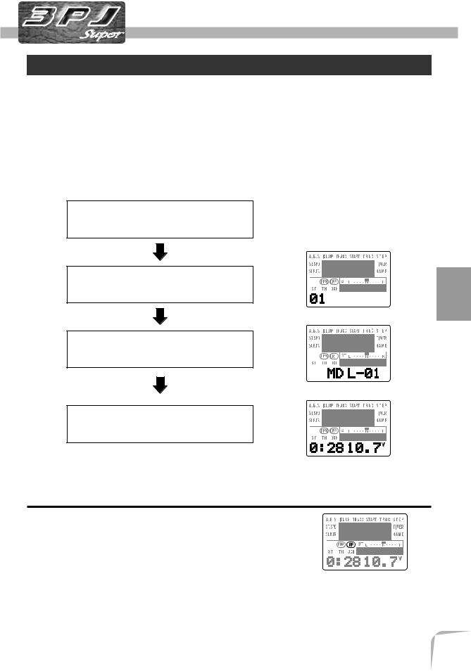
Preparations (Transmitter)
Beforesettingthetransmitterfunctions,checkandsetitems1to3below.
(Display when power switch turned on)
When the power switch is turned on, the currently selected model number is dis- played.Checkifthisnumberisthemodelnumberyouwanttoset-up.Tochangethe modelnumber,usetheModelSelectfunction(page44).
Turn on the transmitter power.
The model number is displayed for about one second.
(Model No.)
The model name is displayed for about two seconds.
(Model name)
The total timer and voltage display initial screen is displayed.
(Total timer & voltage display)
Initial Set-Up
1. RF Output Check
If signals are output normally, RF output monitor “RF” willbedisplayedonthescreen.
If RF is not displayed, check if the transmitter crystal and RFmoduleareinstalled.
If the transmitter is abnormal or faulty, contact your Futabadealer.
29

Up-Set Initial
2. Modulation Mode Check
TheT3PJSUPERtransmitteroutputsignalformatcan |
|
be changed to match the type of receiver. Check if the |
|
modulationmodeissettomatchthereceiverused. |
|
WhenusinganFMreceiver(e.g.,R113F),themodula- |
(PPM) |
tion mode must be set to PPM. When using a PCM re- |
ceiver(e.g.,R113iP),themodulationmodemustbeset to PCM. If this setting is incorrect, change it with the ModeSelect(page93)function.
(PCM)
3. Trims Initial Set-Up
- Steering trim (Trim 1) check
At initial set-up, steering trim (Trim 1) is assigned to digitaltrimDT1abovethesteeringwheel.Operatethe DT1 lever and check if the steering trim display on the screen changes. After checking the trim, set the trim display to the center (N) position.
- Throttle trim (Trim 2) check
At initial set-up, throttle trim (Trim 2) is assigned to digital trim DT2 at the left side of the steering wheel. OperatetheDT2leverandcheckifthethrottletrimdisplayonthescreenchanges.Aftercheckingthetrim,set the trim display to the center (N) position.
- Steering dual rate (D/R) check
At initial set-up, steering dual rate (D/R) is assigned to grip dial GD1 (upper) at the grip of the transmitter. OperatetheGD1dialandcheckiftheD/Rvaluedisplayed on the screen changes. After checking D/R, set the steeringdualrateto100%.
- Throttle ATL (ATL) check
At initial setting, throttle ATL (ATL) is assigned to grip dial GD2 (lower) at the grip of the transmitter. Operate the GD2 dial and check if the ATL value displayedonthescreenchanges.AftercheckingATL,set throttle ATL to 100%.
30
Loading...