


INSTRUCTION MANUAL
1M23N26602

8J-2.4GHz
8-CHANNEL RADIO CONTROL SYSTEM
INSTRUCTION MANUAL
Technical updates and additional programming examples available at: http://www.futaba-rc.com/faq
Entire Contents © 2012 1M23N26602
TABLE OF CONTENTS
Introduction............................................................. |
3 |
Service ...................................................................... |
3 |
Usage Precautions ................................................... |
4 |
.................... |
8 |
Transmitter controls ............................................. |
10 |
Transmitter batteries ............................................ |
12 |
Switch assignment table ....................................... |
13 |
Receiver and servo connections ........................... |
14 |
Charging batteries ............................................... |
15 |
Adjusting the length of the control sticks ........... |
16 |
Range check the radio .......................................... |
17 |
Radio Installation.................................................. |
18 |
Link procedure ..................................................... |
21 |
S.BUS Installation................................................. |
22 |
Transmitter displays & buttons........................... |
21 |
Warning & error displays .................................... |
24 |
Map of ACRO functions....................................... |
26 |
Programming the T8J-2.4GHz Radio ................. |
27 |
(Common Functions) |
|
Model Select ..................................................... |
27 |
Model Copy ...................................................... |
27 |
Model Data Reset............................................... |
28 |
Model Name ...................................................... |
29 |
Parameter ........................................................... |
30 |
Model Type ........................................................ |
30 |
RX select (S-FHSS /FHSS) ............................... |
31 |
ATL .................................................................... |
32 |
LCD adjustment................................................. |
32 |
Battery Type....................................................... |
33 |
Model Data Transmission ................................. |
34 |
Reverse .............................................................. |
35 |
End Point .......................................................... |
36 |
Idle Down .......................................................... |
37 |
Throttle Cut........................................................ |
38 |
D/R,EXP ............................................................ |
39 |
Timer.................................................................. |
42 |
AUX CH ............................................................ |
43 |
Trainer................................................................ |
44 |
Trim.................................................................... |
45 |
Sub Trim ............................................................ |
46 |
Servo .................................................................. |
47 |
Fail Safe ............................................................. |
48 |
Flaperon (ACRO Only) ..................................... |
49 |
Flap Trim (ACRO Only).................................... |
51 |
AIL DIFF (ACRO Only) ................................... |
52 |
Elevon (ACRO Only) ........................................ |
53 |
Ailevator (ACRO Only) .................................... |
54 |
V-Tail (ACRO Only).......................................... |
55 |
Snap-Roll (ACRO Only) ................................... |
56 |
ELE-FLAP (ACRO Only) ................................. |
59 |
Airbrake (ACRO Only) ..................................... |
60 |
THR → Needle .................................................. |
62 |
THR Delay (ACRO Only) ................................. |
63 |
THR-Curve (ACRO Only) ................................ |
64 |
PIT-Curve (ACRO Only)................................... |
64 |
Programmable MIX ........................................... |
65 |
Gyro Sens (ACRO Only) .................................. |
70 |
Swashplate Types (HELI only).......................... |
73 |
Swash AFR (HELI only) .................................. |
75 |
Swash MIX (HELI only) .................................. |
76 |
THR MIX (HELI only)..................................... |
77 |
Swash Ring (HELI only) .................................. |
77 |
Flight Condition<Idle-up,THR-hold> |
(HELI |
only)................................................................... |
78 |
THR Curve (HELI only)................................... |
81 |
PIT Curve (HELI only)..................................... |
81 |
REVO.MIX (HELI only).................................. |
81 |
Offset (HELI only)............................................ |
83 |
Delay (HELI only)............................................ |
84 |
HOV-THR (HELI only).................................... |
85 |
HOV-PIT (HELI only)...................................... |
85 |
HI/LO-PIT (HELI only).................................... |
86 |
Gyro (HELI only) ............................................. |
87 |
Governor (HELI only) ...................................... |
89 |
TX Setting......................................................... |
91 |
2
INTRODUCTION
Thank you for purchasing a Futaba® S-FHSS-2.4GHz* 8J series digital proportional R/C system. This system is extremely versatile and may be used by beginners and pros alike. In order for you to make the best use of system, please consult the manual, our online Frequently Asked Questions (on the web pages referenced below), your hobby dealer, or the Futaba Service Center.
*S-FHSS: SuperFutaba Frequency Hopping Spread Spectrum
Owner’s Manual and Additional Technical Help
This manual has been carefully written to be as helpful to you, the new owner, as possible. There are many pages of setup procedures and examples. However, it need not be your sole resource of setup guidelines for your 8J. For example, pages 27-29 include setup instructions for a basic 4-channel airplane. The Frequently Asked Questions web page referenced below includes this type of step-by-step setup instructions for a variety of other model types, including multi-engine, complex gear installation, 7-servo aerobatic models, 140 degree CCPM, etc.
http://www.futaba-rc.com/faq
Due to unforeseen changes in production procedures, the information contained in this manual is subject to change without notice.
Support and Service: It is recommended to have your Futaba equipment serviced annually during your hobby’s “off season” to ensure safe operation.
IN NORTH AMERICA
Please feel free to contact the Futaba Service Center for assistance in operation, use and programming. Please be sure to regularly visit the 8J Frequently Asked Questions web site at www.futaba-rc.com/faq/. This page includes extensive programming, use, set up and safety information on the 8J radio system and is updated regularly. Any technical updates and US manual corrections will be available on this web page. If you do not us via email for the most rapid and convenient response.
Don’t have Internet access? Internet access is available at no charge at most public libraries, schools, and! " ! ! be printed and saved for future reference, and can be accessed at any hour of the day, night, weekend or holiday. If you do not wish to access the internet for information, however, don’t worry. Our support teams are available Monday through Friday 8-5 Central time to assist you.
FOR SERVICE ONLY:
Futaba Service Center
3002 N. Apollo Drive, Suite 1 |
Please start here for answers to most questions: |
Champaign, IL 61822 |
www.futaba-rc.com/faq/ |
Phone: 217-398-0007 |
FACSIMILE: 217-398-7721 |
www.futaba-rc.com/service.html |
PHONE: 217-398-8970 option 2 |
Email: service@futaba-rc.com |
|
FOR SUPPORT : |
OUTSIDE NORTH AMERICA |
(PROGRAMMING AND USER QUESTIONS) |
|
Please contact your Futaba importer in your region of the world to assist you with any questions, problems or service needs.
Please recognize that all information in this manual, and all support availability, is based upon the systems sold in North America only. Products purchased elsewhere may vary. Always contact your region’s support center for assistance.
3
1.This product may be used for model airplane or surface (boat, car, robot) use. It is not intended for use in any application other than the control of models for hobby and recreational purposes. The product is subject to regulations of the Ministry of Radio/Telecommunications and is restricted under Japanese law to such purposes.
2.Exportation precautions:
(a)When this product is exported from the country of manufacture, its use is to be approved by the laws governing the country of destination which govern devices that emit radio frequencies. If this product is then reexported to other countries, it may be subject to restrictions on such export. Prior approval of the appropriate government authorities may be required. If you have purchased this product from an exporter outside your country, and not the authorized Futaba distributor in your country, please contact the seller immediately to determine if such export regulations have been met.
(b)Use of this product with other than models may be restricted by Export and Trade Control Regulations, and an application for export approval must be submitted. This equipment must not be utilized to operate equipment other than radio controlled models.
# $ % & ! ! ' adjustment, and replacement of parts on this product. Any such changes may void the warranty.
Federal Communications Commission Interference Statement (for U.S.A.)
This equipment has been tested and found to comply with the limits for a Class B digital device, pursuant to Part 15 of the FCC Rules. These limits are designed to provide reasonable protection against harmful interference in a residential installation.
This equipment generates, uses and can radiate radio frequency energy and, if not installed and used in accordance with the instructions, may cause harmful interference to radio communications. However, there is no guarantee that interference will not occur in a particular installation. If this equipment does cause harmful interference to radio or television reception, which can be determined by turning the equipment off and on, the user is encouraged to try to correct the interference by one or more of the following measures:
--Reorient or relocate the receiving antenna.
--Increase the separation between the equipment and receiver.
--Connect the equipment into an outlet on a circuit different from that to which the receiver is connected. --Consult the dealer or an experienced radio/TV technician for help.
CAUTION:
To assure continued FCC compliance:
Any changes or modifications not expressly approved by the grantee of this device could void the user's authority to operate the equipment.
Exposure to Radio Frequency Radiation
To comply with FCC RF exposure compliance requirements, a separation distance of at least 20cm must be maintained between the antenna of this device and all persons.
This device must not be co-located or operating in conjunction with any other antenna or transmitter.
Compliance Information Statement (for U.S.A.)
This device, trade name Futaba Corporation of America, model number R2008SB, complies with part15 of the FCC Rules. Operation is subject to the following two conditions:
(1)This device may not cause harmful interference, and
(2)This device must accept any interference received, including interference that may cause undesired operation.
The responsible party of this device compliance is: Futaba Service Center
3002 N Apollo Drive Suite 1, Champaign, IL 61822 U.S.A.
TEL (217)398-8970 or E-mail: support@futaba-rc.com (Support) TEL (217)398-0007 or E-mail: service@futaba-rc.com (Service)
4

Meaning of Special Markings
Pay special attention to safety where indicated by the following marks:
 DANGER - Procedures which may lead to dangerous conditions and cause death/serious injury if not carried out properly.
 WARNING - Procedures which may lead to a dangerous condition or cause death or serious injury! ! % physical damage is high.
 CAUTION - Procedures where the possibility of serious injury to the user is small, but there is a danger of injury, or physical damage, if not carried out properly.
= Prohibited |
= Mandatory |
Warning: Always keep electrical components away from small children.
FLYING SAFETY
 WARNING
To ensure the safety of yourself and others, please observe the following precautions:
Have regular maintenance performed. Although your 8J protects the model memories with non-volatile EEPROM memory (which does not require periodic replacement) and not a battery, the transmitter still should have regular checkups for wear and tear. We recommend sending your system! ; K Y Y Z service.
NiCd Battery
Charge the batteries! (See Charging the NiCd batteries, p. 15, for details.) Always recharge the! [ ! !" ! your 8J’s built-in timer, and during the session pay attention to the duration of usage.
" # $ battery warning systems, intended only as a precaution, to tell you when to recharge. Always% ' "
Where to Fly
" ' \ !! Z !! ]; ! $
\ $ ^ $ _ ` {|| chartered clubs across the country. Through any one of them, instructor training programs and insured newcomer training are available. Contact the AMA at the address or toll-free phone number below.
Academy of Model Aeronautics
5161 East Memorial Drive
Muncie, IN 47302
Tele. (800) 435-9262
Fax (765) 289-4248
or via the Internet at http:\\www.modelaircraft.org
5

 $ as well as the presence and location! ~ power lines, tall buildings, or communication facilities as there may be radio interference in their vicinity.
! ! * * ' * mile range, or you may lose control of your aircraft or cause someone else to lose control.
To prevent possible damage to your radio gear, turn the power switches on and off in the proper sequence:
1.Pull throttle stick to idle position, or otherwise disarm your motor/engine.
2.Turn on the transmitter power and allow your transmitter to reach its home screen.
# K !
4.Turn on your receiver power.
{ • ! € problem.
•%
the proper surface/throttle movements. Then turn the transmitter back on.
6.Start your engine.
7.Complete a full range check (see p. 22).
[ ! Z Z motor/engine.
9.Turn off receiver power.
10.Turn off transmitter power.
yourengine, or in the case of electric-powered or gasoline-powered models, the engine may unexpectedly turn on and cause a severe injury.
 + wind won't tip it over. If it is knocked over, the throttle stick may be accidentally moved, causing the engine to speed up. Also, damage to your transmitter may occur.
 In order to maintain complete control of your aircraft it is important that it remains visible at all times. Flying behind large objects such as buildings, grain bins, etc. is not suggested. Doing so may result in the reduction of the quality of the radio frequency link to the model.
 Do not cover/hold the built-in antenna part of T8J-2.4G transmitter by your hand during " Do not put any conductive plate/sticker on the antenna part. Otherwise, the operating range may become shorter.
 As with all radio frequency transmissions, the strongest area of signal transmission is from the sides of the transmitter's antenna. As such, the antenna should not be pointed directly at the model. If your
 Don’t fly in the rain! Water or moisture may enter the transmitter through the antenna or stick openings and cause erratic operation or loss of control. If you must fly in wet weather during a contest, be sure to cover your transmitter with a plastic bag or waterproof barrier. Never fly if lightning is expected.
6

A QUICK INTRODUCTION TO THE 8J SYSTEM
Note that in the text of this manual, beginning at this point, any time we are using a feature’s specialized name or abbreviation as seen on the screen of the 8J, that name, feature, or abbreviation will be exactly as seen on the radio’s screen, including capitalization and shown in a DIFFERENT TYPE STYLE for clarity. AnySWITCH A, VR, or the THROTTLE STICK, those words will be displayed as they are here.
TRANSMITTER:
• ‚ Y ! Y Y % YZ quick, easy setup.
• ! ' &
• ^ACRO)
|
|
•V-TAIL |
• • ; ^FLAPERON and AIL-DIFF_ |
•ƒ $„ |
|
|
|
•ELEVON |
• • … ; ^AILEVATOR) |
|
|
|
|
•AIRBRAKE |
• ; † ^‡ ! _ |
|
|
|
• ˆ ^[ KK‰$ Š#_^HELI) |
|
|||
|
|
• # ] |
|
• • ‰ K K |
|
|
|
• † $„ |
•ƒ $„ ; ; K |
||
|
|
• ‹ |
|
•ƒ $„ |
|
• TRIM LEVERS for rapid yet precise trim adjustment - no remembering to “store trims” between models and no more “bumped trims” during transport.
•IDLEDOWN (ACRO), THR-CUT (ACRO/HELI) (engine shut off), setups to allow precise engine/motor control for taxi and landings.
• `|
• Œ Z % !
• • ! ! #Y
• …SWITCHES, and DIAL; completely assignable in most applications.
• • ‘ ’ ^FUNC) setting, which allows the student to use the 8J’s mixing, helicopter, and other programming functions even with a 4-channel buddy box. (Optional trainer cord required.)
• ‰ ……‰†“$! Z !
• [” ^$ `_ and a notched throttle to minimize throttle changes with rudder input. Defaults to ACRO model type.
• [”ˆ Y Y hand, and a smooth, ratchet-less (unsprung) throttle for perfect hovering. Defaults to HELI(H-1 swashplate type) model type.
• K ` • # ‡ ^; ‰ Š•_
• • ! Y
• • `
7

RECEIVER: R2008SB
•• †`||[;~ ; ~]; ! used with conventional system servos, etc. in addition to S.BUS system compatible servos and gyros, etc.
Link switch LED |
(Connectors) |
Channel 1 output |
|
|
|
|
|
Channel 7 output |
|
|
for conventional |
|
|
system |
|
|
S.BUS Port |
|
|
Channel 8 output |
|
|
for conventional |
|
|
system |
|
R2008SB |
/Battery terminal |
Antenna |
|
|
•• ' ;Y ˆ;; ˆ;; ˆ ˆ;; •Kˆ 4CH. Moreover, in FHSS, F/S also serves as only 2CH. Choose S-FHSS mode, if R2008SB and T8J are used.
SERVOS
• ‰
•• ! ”Y ! servos.
CONTENTS AND TECHNICAL SPECIFICATIONS
^; !% _
Your 8J system includes the following components:
• T8J Transmitter
• R2008SB Receiver
• ;
• „
• Œ Z
* The set contents depend on the type of set.
Transmitter T8J
(2-stick, 8-channel, S-FHSS system, Built-in Dual Antenna Diversity)
Transmitting frequency: 2.4GHz band
Power supply: 4-AA 1.2V Dry Cell batteries; 4.8V total (sold separately)
or HT5F1700B Ni-MH battery (option) or FT2F2100B Li-Fe battery (option)
Receiver R2008SB
(Dual Antenna Diversity)
Power requirement: 4.8V to 7.4V battery or regulated output from ESC, etc. (*1)
Size: 0.98 x 1.69 x 0.55 in. (24.9 x 42.8 x 14.0 mm) Weight: 0.34 oz. (9.5g)
(*1) Be sure that when using ESC's regulated output the capacity of the ESC must meet your usage condition.
8
The following additional accessories are available from your dealer. Refer to a Futaba catalog for more information:
• ˆ•{ •–||~/FT2F2100B Transmitter battery pack - the transmitter battery pack may be easily exchanged„
• • Y ! ! ! the instructor on a separate transmitter. Note that the 8J transmitter may be connected to another 8J system, as well as to many other models of Futaba transmitters. The 8J transmitter uses the newer micro (rectangular type) cord plug. Both new-to-new and new-to-round plug style trainer cords are available.
• Œ Z Y Z ! •[” Z€ €
• \Y „ ! Y ƒ ! „ \Y Y duty version with heavier wire, are available to aid in your larger model and other installations.
• {Y ^— |˜_ ! Z Y ! ! ^ „ labeled otherwise) is designed to work with 4.8V (Ni-Cd 4 cells) or 6.0V (Ni-Cd 5 cells or alkaline 4 cells). ] — |˜ Z torque. However, because of this faster current draw, a 5-cell battery pack of the same mAh rating will last approximately 3/4 the time of a 4-cell pack.
• ƒ Y ! !
• ƒ ^ƒ˜• ƒ\–|• Kƒ\–{|_ Y % maintain a constant head speed regardless of blade pitch, load, weather, etc.
• † Y ! ^“ ` ‡ƒˆ' ;Y ˆ;;™ FHSS Type)
9
TRANSMITTER CONTROLS - AIRPLANE
VR
Flap Trim Control
This controls CH6, and if flaperon mixing is activated controls the flap.
Built-in Antenna
Carrying Handle
Digital Trim 5
/CH7 Control
SW(B)
Rudder Dual Rate Switch
SW(A)
Elevator Dual Rate
Switch
SW(F)
Snap Roll or
Trainer Switch
SW(E)
Landing Gear
Switch
/CH5
Digital Trim 6
/CH8 Control
Rudder /Throttle Stick
Power
LED*
Throttle
Trim Lever
Rudder
Trim Lever
END Key
Power Switch
(Up position: ON)
Hook
(for optional neckstrap)
SW(C)
Elevator - Flap Mixing or
Airbrake Mixing Switch
SW(D)
Aileron Dual Rate Switch
 SW(H)
SW(H)
SW(G)
Elevator
/Aileron
Stick
Elevator Trim Lever
 Aileron Trim Lever


 Key
Key
Key
Jog Key
 LCD Panel
• [”$ ` ! \ !
the setting menu for the function you wish to move. 10

TRANSMITTER CONTROLS - HELI
VR
CH8 Knob
SW(B)
Rudder Dual Rate Switch
SW(A)
Elevator Dual Rate
Switch
SW(F)
Idle-up 3 Switch /Gyro/CH5
SW(E)
Idle-up 1&2
Switch
Digital Trim 6
Throttle/Collective |
Pitch & Rudder Stick |
Power |
LED |
Throttle/Collective
Pitch Trim Lever
Rudder
Trim Lever
END Key
Built-in Antenna
Carrying Handle
Digital Trim 5
SW(C)
Governor Switch/CH7
SW(D)
Aileron Dual Rate Switch
SW(H)
Trainer Switch
SW(G) |
Throttle - Hold Switch |
Elevator
/Aileron
Stick
Elevator Trim Lever
 Aileron Trim Lever


 Key
Key
Key
Jog Key
Power Switch |
|
|
|
|
||
LCD Panel |
||||||
(Up position: ON) |
|
|||||
|
||||||
|
|
|
|
|
|
|
|
Hook |
|
|
|
||
(for optional neckstrap) |
|
|||||
• [”ˆ$ ` ! \ !
the setting menu for the function you wish to move. 11

INSTALLATION AND REMOVAL OF THE TRANSMITTER BATTERY
The T8J transmitter is designed to work with either four (4) AA alkaline dry cell batteries, or HT5F1700B/ FT2F2100B battery pack, both available separately. The transmitter batteries used are a matter of personal preference. AA Alkaline batteries are available at any local hobby shop, grocery store, etc. A battery pack will need to be purchased from a hobby shop.
Trainer function connector
push and slide down
Remove the battery BOX if you choose to use the optional HT5F1700B/FT2F2100B battery pack, which can be recharged from the transmitter.
And "BATT TYPE" in a PARAMETER is changed into "5CELL" in the procedure of P.33.
 Battery cover
WARNING
Be careful not to drop the battery.
Never disconnect the battery connector from the T8J transmitter after turning off the power until the screen is completely blank and the transmitter has shut down completely.
*Internal devices such as memories may be damaged.
*If there is any problem, the message "Backup Error" will be shown the next time when you turn on the power of the transmitter. Do not use the transmitter as it is. Send it to the Futaba Service Center.
WARNING
Do not connect any other chargers except the special charger to this charging connector.
*If you take out the Ni-MH battery HT5F1700B from the transmitter, you can use the optional quick charger CR2000 corresponding to Ni-MH battery.
NOTE: If you need to remove or replace the transmitter battery, do not pull strongly on the battery wires to remove it. Insert the connector straight as shown.
NOTE: This plug is for charging HT5F1700B. The other battery cannot be charged. FT2F2100B is removed from a transmitter, and charges with an exclusive charger(LBC-4E5).
12

SWITCH ASSIGNMENT TABLE
• • ! ˜† [” $ ` below.
• $ [” ! Y Z
• ~ {Y[ Z % ! AUX-CH.
• Œ !
• [” $ • [”ˆ [” ! check that you have the desired switch assignment for each function during set up.
Switch/VR |
Airplane (ACRO) |
Helicopter (HELI) |
A or H |
|
|
SWITCH A |
elevator dual rate |
elevator dual rate |
SWITCH B |
rudder dual rate |
rudder dual rate |
SWITCH C |
up = ELE-FLP on |
governor |
|
center/down = IDLE-DOWN |
|
|
down = AIRBRAKE on |
|
SWITCH D |
aileron dual rate |
aileron dual rate |
SWITCH E or G* |
landing gear/ch 5 |
throttle hold/ch5 |
SWITCH F or H* |
snap roll/trainer |
trainer/THR-CUT |
SWITCH G or E* |
none |
idle-up 1 and 2 |
SWITCH H or F* |
none |
idle-up3/gyro |
VR |
™ — |
CH8 |
|
^ FLAPERON on) |
|
*On the 8JA Mode 2 transmitters, the TOP LEFT SWITCHES are spring-loaded and 2-position; on the 8JA Mode 1, 8JH, those switches are on the right side. For consistency, the switch position’s designation remains the same (upper left is F, etc), but the functions are moved to match the switch type.
TO TURN ON THE 8J SYSTEM
First make sure the throttle stick is in the low throttle position.
Push up to turn on.
*If the throttle stick is not in the low position,
you'll have an alarm until the stick is in the low position.
13

RECEIVER AND SERVO CONNECTIONS
Receiver |
|
Output and |
Aircraft (ACRO) |
Channel |
|
1 |
ailerons/aileron-11™ ! Y` • Y•2 |
2 |
elevator |
3 |
throttle |
4 |
rudder |
5 |
spare/landing gear/aileron-21,3™ ! Y• Y`2,3 |
6 |
™ ^ _™ ! Y• Y`2 |
7 |
spare/aileron-21 |
8 |
spare/elevator-24/mixture control |
1 Aileron Differential mode (AILE-DIFF). 2 Flaperon mode.
3 Using Second Aileron option, second aileron servo output is sent to channels 5 and 6. ( AILE-2)
4 AILEVATOR (dual elevator) mode.
(NORMAL)
(Wing Type)
ACRO (FLAPERON)
AIL22 |
|
AIL12 |
FLP12 |
|
|
(CH6) |
|
FLP22 |
|
|
(CH1) |
|
ACRO |
AIL |
|
(FLAP) |
|
|
(CH1) |
|
|
|
AIL21
(CH7) FLP AIL11 (CH6) (CH1)
(Tail Type)
(V-TAIL) |
(AILVATOR) |
|
ELE2 |
ELE1 |
ELE2 |
|
|
RUD1 |
ELE1 |
||
ELE |
(CH4) |
RUD2 |
AIL4 |
|
(CH2) |
|
(CH2) |
(CH8) |
AIL3 |
|
|
|
|
(CH2) |
Receiver |
|
Output and |
Helicopter (HELI) |
Channel |
|
1 |
aileron (cyclic roll) |
2 |
elevator (cyclic pitch) |
3 |
throttle |
4 |
rudder |
5 |
spare/gyro |
6 |
pitch (collective pitch) |
7 |
spare/governor |
8 |
spare/mixture control |
(Swash Type)
$,/ $LOHURQ 6HUYR (/( (OHYDWRU 6HUYR 3,7 3LWFK 6HUYR
14

CHARGING THE BATTERIES (When the rechargeable battery option is used) Charging Your System’s Batteries
1.Connect the transmitter charging jack and batteries to the transmitter and receiver connectors of the charger.
2.Plug the charger into a wall socket.
3.Check that the charger LED lights.
Charger
TX: Transmitter charging indicator RX: Receiver charging indicator
 To transmitter charging jack
Receiver battery
According to the description of the battery to be used and its exclusive charger, please use it after carrying out full charge.
We recommend charging the batteries with the charger supplied with your system. Note that the use of a fast charger may damage the batteries by overheating and dramatically reduce their lifetime.
When HT5F1700B is chosen, HBC-3A (4) is recommended. When charging FT2F2100B, Please make sure to remove the battery from the system to charge it. Charger for this battery is recommended to use LBC-4E5.
Battery Care and Precautions
~ ! and/or receiver battery packs. These are included to serve only as general guidelines, and are not intended to replace or supersede the information provided by the battery and/or charger manufacturer. For complete information, please refer to the instructions that are included with the battery pack(s) and/or chargers that accompany the products purchased.
•Do not allow children to charge battery packs without adult supervision.
•Do not charge battery packs that have been damaged in any way. We strongly suggest frequent inspection of the battery packs to ensure that no damage has occurred.
•Do not to allow batteries to overheat! If overheated, disconnect the battery from the charger immediately and allow to cool.
• ‹ „ Y !
•Do not deep cycle NiMH batteries as permanent damage could result.
•Never charge batteries on a surface that may become hot, or may be impacted by the heat.
•Immediately end the charging procedure if either the batteries or charger itself become overly hot.
•NiMH cells do not exhibit the “memory effect” like NiCd cells, so little cycling is needed. Store NiMH packs with some voltage remaining on the cells (refer to battery supplier).
•NiMH cells have a self-discharge rate of approximately 20-25% (compared to 15% for NiCd batteries). It is important to recharge NiMH batteries immediately prior to use.
•Never connect the battery in reverse. Reverse connection will cause the battery to overheat or will damage the inside of the charger.
•Do not add an additional charge after charging.
•Never charge with a current exceeding the nominal capacity (lC) of the rechargeable battery.
•If a battery is charged with a current exceeding 1C, the battery will overheat and deteriorate.
•Do not connect two battery packs or more to one output terminal.
•Avoid extremely cold and hot places and the direct sunlight when you charge batteries.
•It is recommended to perform charging within the 10 ~ 30°C (50-85°F) range. Otherwise, it may cause abnormal charging and overheat.
15

ADJUSTING THE IENGTH OF THE CONTROL STICKS
Stick tip A Locking piece B
Stick lever tension adjustment
\ Z Z transmitter more comfortable to hold and operate. To lengthen or€ Z Z Z ! locking piece B and turning stick tip A counterclockwise. Next, move the locking piece B up or down (to lengthen or shorten). When the length feels comfortable, lock the position by turning locking piece B counterclockwise.
Four screws are removed and rear case is removed.
Aileron
Elevator |
Rudder |
Stick |
Stick |
Mode 2 transmitter with rear case removed.
\ % Z • % springs, you’ll have to remove the rear case of the transmitter. First, remove the battery cover on the rear of the transmitter. Next, unplug the battery wire, and remove the battery from the transmitter. Next, using a screwdriver, remove the four screws that hold the transmitter’s rear cover in position, and put them in a safeƒ € Œ € !
Using a small Phillips screwdriver, rotate the adjusting screw for each stick for the desired spring tension. The tension increases when the adjusting screw is turned clockwise. When you are satisfied with the spring tensions, reattach the transmitter's rear cover. When the cover is properly in place, reinstall and tighten the four screws. Reinstall the battery and cover.
+ screw is clockwise. |
+ screw is counter-clockwise. |
|
A screw is kept |
|
from coming out |
|
from a line. |
Stick tension maximum |
Stick tension minimum |
A screw touches a case. |
ADJUSTING DISPLAY CONTRAST
To adjust the display contrast, from the home menu press and hold the END BUTTON. Push the KEY while still holding the END BUTTON:
KEY to brighten
KEY to darken the display
16

RANGE CHECK THE RADIO
Z ! !Z ! ^! ! Z ! _Z ! adequate operational range.
We have installed a special “Power Down Mode” in the T8J in order to perform an operational ground range check. During this mode, the RF power is reduced in order to test the operational range of the T8J.
To activate the Power Down Mode and Perform A Range Check:
1) To activate the “Power Down Mode” please hold down the JOG KEY and then turn the transmitter switch on. A power mode screen comes out. JOG KEY is pushed where Power Down is chosen. When this mode is active the Purple LED on the Lighting front of the transmitter will provide users with an audible and visual indication that the transmitter is in the “Power Down Mode”.
Audibly, the transmitter will beep one time every three seconds. Visually, the LCD screen will display “POWER DOWN MODE”. The words “POWER DOWN MODE” will blink as an additional reminder that the transmitter is in the “Power Down Mode”.
2)With the “Power Down Mode” activated, walk away from the model while simultaneously operating theˆ !\ ! ! Z „ #|Y{| control.
3)If everything operates correctly, return to the model. Push END KEY and complete power down mode. Set the transmitter in a safe yet accessible location so it will be within reach after starting the engine. Be certain the throttle stick is all the way down, and then start the engine. Perform another range check with your assistant holding the model and the engine running at various speeds.
% ! ! ‹ Œ“• ¡ ‚ Z servo connections or binding pushrods. Also be certain that the battery has been fully charged.
‡_ Œ…˜…† ‘‰ ‹ $ ’
Servo test operation at the time of Power Down Mode:
‹ ‰ ‹ Z ^ moves to right and left slowly).
1)A "SERVO" is chosen from a menu.
2)JOG KEY is moved to a side and 2 pages is called. Next, JOG KEY is moved down and CH is displayed.
3)CH of the servo which wants to operate is chosen. Then, the + KEY is pressed and it is made ACT.
The servo selected during Power Down Mode operates alone, allowing you to check its operation. It is during Power Down Mode starting, and if "SERVO TEST" is turned ON, it will move.
*In the Power Down Mode, the throttle servo does not operate. (Slow keeping) ¢ˆ „ Œ“†
DANGER
= > ? @Z # [ is active. *Control is impossible and your model crashes.
17
RADIO INSTALLATION
Follow these guidelines to properly mount the servos, receiver and battery.
• $ Z alignment tab on the battery, switch and servo connectors is oriented correctly and “keys” into the corresponding notch in the receiver or connectors before plugging them in. When unplugging connectors, never pull on the wires. Always pull on the plastic connector instead.
• ^ _ „ to extend the length of the servo lead. Additional Futaba extension cords of varying lengths are available from your hobby dealer. Always use an extension of the proper length. Avoid plugging multiple extensions together to attain your desired length. If distance is greater than 18” or multiple or high current draw servos are being used, use Futaba Heavy-Duty servo extensions.
• rubber grommets. |
Servo |
Rubber |
Servo |
Rubber |
Do not over tighten the screws. No part of the servo casing |
grommet |
grommet |
||
should contact the mounting rails, servo tray or any other part |
|
|
|
|
of the airplane/helicopter structure. Otherwise, vibration will be |
|
|
|
|
transmitted to the servo, causing premature wear and/or servo |
|
|
|
|
failure. |
|
|
|
|
• Œ ! ^• ` # ‡_ ! ‡Y 

 The numbers indicate how many degrees each arm is “off” from 90 degrees to correct for


 minute manufacturing deviations from servo to servo.


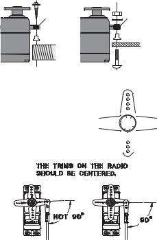
• • K the arm that will be perpendicular to the pushrod when placed on the servo.
• Z arms do not bind or contact each other. Also make sure the controls do not require excess force to operate. If there is an objectionable buzzing sound coming from a servo, there is probably too much resistance in the control. Find and correct the problem. Even if there is no servo damage, excess battery drain will result.
• ] mounting plate from the receiver on/off switch as a template for the cutout and screw holes. Mount the switch on the side of the fuselage opposite the engine exhaust, and where it won’t be inadvertently turned on or off during handling or storage. Be certain the switch moves without restriction and “snaps” from ON to OFF, and that the cutout allows full motion of the switch in both directions.
• " ƒ frame between the switch and switch cover and securely tighten the screws. Different models might require different installations. If so, please follow the model's instruction manual.
18

• • ! ! Z ! vibration during flight, provide a slight amount of slack or extra so that the wire sticks out slightly and fasten it at suitable points. In addition, periodically check the wire during daily maintenance.
Margin in the lead wire. Fasten about 5-10cm from the servo outlet so that the lead wire is neat.
IMPORTANT: Since the 2.4GHz have different characteristics than that of the conventional 27MHz and 72MHz frequencies, please read this section carefully to maximize your enjoyment of the 2.4GHz system.
Receiver's Antenna Installation:
• \ †`||[;~ appearance from the standard Futaba receiver. These receivers incorporate two separate antennas into their design which enables them to receive
the radio frequency transmission at two different locations.
Futaba's dual antenna diversity then seamlessly selects the best signal reception between these antennas to ensure that there is no loss of signal.
• • ! ! &
1. The two antennas must be kept as straight as possible. Otherwise it will reduce the effective range.
2. The two antennas should be placed at 90 degrees to each other.
• ! Z the antennas away from each other as much as possible.
Larger models can have large metal objects that can attenuate the RF signal. In this case the antennas should be placed at both sides of the model. Then the best RF signal condition is obtained at any
3.The antennas must be kept away from conductive materials, such as metal, carbon and fuel tank by at least a half inch. The coaxial part of the antennas does not need to follow these guidelines, but do not bend it in a tight radius.
4.Keep the antennas away from the motor, ESC, and other noise sources as much as possible.
19
Antenna |
Antenna |
*The two antennas should be placed at 90 degrees to each other.
*The main purpose of the photo demonstrates how the antenna should be placed.
• † ˜ ! " & • ~ vibration, shock, and temperature extremes. For protection, wrap the receiver in foam rubber or other vibration-absorbing materials. It is also a good idea to waterproof the receiver by placing it in a plastic bag and securing the open end of the bag with a rubber band before wrapping it with foam rubber. If you accidentally get moisture or fuel inside the receiver, you may experience intermittent operation or a crash. If in doubt, return the receiver to our service center for service.
20

LINK PROCEDURE (T8J transmitter/R2008SB):
Each transmitter has an individually assigned, unique ID code. In order to start operation, the receiver must be linked with the ID code of the transmitter with which it is being paired. Once the link is made, the ID code is stored in the receiver and no further linking is necessary unless the receiver is to be used with another transmitter. When you purchase additional R2008SB receivers, this procedure is necessary; otherwise the receiver will not work.
1.Bring the transmitter and the receiver close to each other, within 20 inches (half meter).
2.Turn on the transmitter.
3.Turn on the receiver.
4.Press and hold the Link switch more than two (2) seconds. When the link is complete, the LED in the receiver changes to solid green. When the ID cannot be read due to the surrounding environment, try reading it with the transmitter and receiver touched.
• ;Y ˆ;;™ ˆ;; „ Z transmitter. In this case, even if the receiver's LED stays solid green, unfortunately the receiver might have established a link to one of other transmitters. This is very dangerous if you do not notice this situation. In order to avoid the problem, we strongly recommend you to doublecheck whether your receiver is really under control by your transmitter by giving the stick input and then checking the servo response.
Please refer the table below for LED status vs receiver's condition.
|
|
LED Indication |
Green |
Red |
Status |
Off |
Solid |
No signal reception |
|
|
|
Solid |
Off |
Receiving signals |
|
|
|
Blink |
Off |
Receiving signals but ID is unmatched |
|
|
|
Alternate blink |
Unrecoverable error (Memory, etc.) |
|
|
|
|
 WARNING
 After the linking is done, please cycle receiver power and check if the receiver to be linked is really under the control by the transmitter to be linked.
 Do not perform the linking procedure with motor's main wire connected or with the engine operating as it may result in serious injury.
21

S.BUS INSTALLATION
This set uses the S.BUS system. The wiring is as simplified and clean mounting as possible, even with models that use a large number of servos. In addition, the wings can be quickly installed to the fuselage without any erroneous wiring by the use of only one simple wire, even when there are a large number of servos used.
£" ; ~]; „ !
£• ; ~]; ; ~]; ' ! ^; ! ;~KY•_ £• ; ~]; ^ Kˆ _! „

 Receiver
6 %86 |
%DWWHU\ |
3RUW |
|
6 %86 |
|
0DOH WR 0DOH |
6ZLWFK |
|
|
FRQQHFWRUV |
7HUPLQDO ER[ |
|
●S.BUS Servo
Since the channel number is memorized by the S.BUS itself, any connector can be used. When the SBD-1 (sold separately) is used, ordinary servos can be used with the S.BUS system.
●7HUPLQDO ER[ 
Four connectors can be inserted
|
|
●+8% |
+8% |
+8% |
+8% Orange |
|
|
Three connectors can be |
|
|
inserted. |
|
6 %86 6HUYR |
Green |
|
●+8% |
|
|
|
|
|
|
$QRWKHU SRZHU VXSSO\ |
|
+8% |
Used when using a separate |
|
power supply battery. |
|
|
|
|
|
$QRWKHU SRZHU VXSSO\ |
|
+8% |
+8% |
●When separate power supply used |
|
|
When a large number of servos is used or |
|
|
when high current servos are used, the servos |
|
%DWWHU\ |
can be driven by a separate power supply by |
|
|
using a separate Power Supply 3-way Hub. |
6 %86 6HUYR
 WARNING
 • ¤ Z!
 Do not insert or remove the servo connector while the receiver power is ON.
Since the S.BUS servo switches the operation mode automatically according to the type of signal (S.BUS signal/PWM signal) from the receiver, if the connector is inserted or removed while the power is ON, an S.BUS connected servo will be erroneously recognized and may stop.
 Please make sure that you use a battery that can deliver enough capacity for the number and kind of servos used. Alkaline batteries cannot be used.
22

TRANSMITTER DISPLAYS & BUTTONS
" ! ! !~ !! ¡ ! reversed, and travels and trims will be wrong, potentially leading to a crash.
* \ ]^
Total timer display <TIMER>
Shows the cumulated ON time. (hours:minutes)
Up/down timer display <ST1.ST2>
(minutes:seconds)
Model timer display <MDL>
Shows the cumulated ON time for each model.(hours:minutes)
System timer display <SYS>
Shows the cumulated ON time.(hours:minutes)
Resetting timers:
Select the desired timer with JOG KEY. The timer display flashes. To reset the timer, press JOG KEY.
Timers
Model number and name
Throttle trim display
END
Key
Model type
System
"S-FHSS" "FHSS"
Output display
Battery |
4CELL TYP 5CELL TYP |
|||||||||
voltage |
|
|
|
|
|
|
|
|
|
|
|
|
|
|
|
|
|
|
|
|
|
|
|
|
|
|
|
|
|
|
|
|
Elevator trim display
key
key
Jog key
Rudder trim |
Aileron trim |
display |
display |
JOG KEY:
Control JOG KEY to scroll up/scroll down/scroll left/scroll right and select the option to edit within a function. When the menu has multiple pages, move the JOG KEY horizontally (left or right).
Press JOG KEY to select the actual function you wish to edit from the menu.
Press JOG KEY and hold one second to confirm major decisions, such as the decision to: select a different model from memory, copy one model memory over another, trim reset, store channel position in FailSafe, change model type, reset entire model, condition of a helicopter setup is changed. An on screen inquiry will ask if you are sure.
Press JOG KEY again to accept the change.
KEY:
Press and hold KEY for one second to open programming menus. It uses for change of a setup, or a numerical increase. Change of the page of a menu can also be performed.
KEY:
It is used for change of a setup, or reduction of a number. Change of the page of a menu can also be performed.
END BUTTON:
Press END BUTTON to return to previous screen. Closes functions back to menus, closes menus to start-up screen.
23

WARNING & ERROR DISPLAYS
An alarm or error indication may appear on the display of your transmitter for a number of reasons, including when the transmitter power switch is turned on, when the battery voltage is low, and several others. Each display has a unique sound associated with it, as described below.
LOW BATTERY ERROR: Warning sound: Continuous beep until transmitter is powered off.
The LOW BATTERY warning is displayed when the transmitter battery voltage drops below 4.1V. (5CELL mode 4.9V)
Land your model as soon as possible before loss of control due to a dead battery.
MIXING ALERT WARNING: Warning sound: Several times of beeps (repeated until problem resolved or overridden)
The MIXING ALERT warning is displayed to alert you whenever you turn on the transmitter with any of the mixing switches active. This warning will disappear when the offending switch or control is deactivated. Switches for which warnings will be issued at power-up are listed below. Throttle cut,
idle-down, snap roll, airbrake, throttle-stick and condition. If turning a switch OFF does not stop the mixing warning: When the warning does not stop even when the mixing switch indicated by the warning display on the screen is turned off, the functions described previously probably use the same switch and the OFF direction setting is reversed. In short, one of the mixings described above is not in the OFF state. In this case, reset the warning display by pressing both / KEY at the same time. Next, change one of the switch settings of the duplicated mixings.
*If "ESC mode" is chosen by "THR.CUT", a THR CUT will not start warning.
BACKUP ERROR: Warning sound: Several times of beeps (repeated continuously)
The BACKUP ERROR warning occurs when the transmitter memory is lost for any reason. If this occurs, all of the data will be reset when the power is turned on again.
# : all programming has been erased and is not available. Return your transmitter to Futaba for service.
24

AIRCRAFT (ACRO) MENU FUNCTIONS
Model Select ..................................................... |
27 |
Model Copy ...................................................... |
27 |
Model Data Reset............................................... |
28 |
Model Name ...................................................... |
29 |
Parameter ........................................................... |
30 |
Model Type ........................................................ |
30 |
RX select (S-FHSS /FHSS) ............................... |
31 |
ATL .................................................................... |
32 |
LCD adjustment................................................. |
32 |
Battery Type....................................................... |
33 |
Model Date Transmission ................................. |
34 |
Reverse .............................................................. |
35 |
End Point .......................................................... |
36 |
Idle Down .......................................................... |
37 |
Throttle Cut........................................................ |
38 |
D/R, EXP ........................................................... |
39 |
Timer.................................................................. |
42 |
AUX CH ............................................................ |
43 |
Trainer................................................................ |
44 |
Trim.................................................................... |
45 |
Sub Trim ............................................................ |
46 |
Servo .................................................................. |
47 |
Fail Safe ............................................................. |
48 |
Flaperon (ACRO Only) ..................................... |
49 |
Flap Trim (ACRO Only).................................... |
51 |
AIL DIFF (ACRO Only) ................................... |
52 |
Elevon (ACRO Only) ........................................ |
53 |
Ailevator (ACRO Only) .................................... |
54 |
V-Tail (ACRO Only).......................................... |
55 |
Snap-Roll (ACRO Only) ................................... |
56 |
ELE-FLAP (ACRO Only) ................................. |
59 |
Airbrake (ACRO Only) ..................................... |
60 |
THR → Needle ................................................. |
62 |
THR Delay (ACRO Only) ................................. |
63 |
THR-Curve (ACRO Only) ................................ |
64 |
PIT-Curve (ACRO Only)................................... |
64 |
Programmable MIX ........................................... |
65 |
ƒ\†“ ;…Œ; ^ K†“ “ _ ............................. |
70 |
25

MAP OF ACRO FUNCTIONS
(Startup screen)
To return to the Startup screen, |
To enter the Menu, |
|
press the End key. |
||
press the + key for one second. |
||
|
||
|
( for one second) |
|
(Menu 1/3) |
(Menu 2/3) |
|
or |
or |
ACRO Menu
(Menu 3/3)
Press Key to page up and down through the 3 pages of screens
in each menu. Note that all functions which have more than one page have a <1/3> indicator in the upper right hand corner to indicate page 1 of 3 or page 2 of 3 / 3 of 3.
Use Jog Key to highlight function in Menu screen. Then press the Dial to choose that function.
Jog Key Up/Down |
Switch Up |
Stick Up |
Jog Key Left/Right |
Switch at Center |
Stick Right |
Press Jog Key |
Switch Down |
Stick Down |
Press Key |
Turn VR Right |
Stick Left |
Press Key |
Turn VR Left |
|
End Selection |
|
|
26

A LOOK AT THE RADIO'S FUNCTIONS STEP BY STEP
MODEL SELECT submenu: includes three functions that manage model memory: MODEL SELECT, MODEL COPY and MODEL RESET. Since these functions are all related, and are all basic features used with most models, they are together in the
MODEL SELECT submenu.
MODEL SELECT: This function selects which of the 20 model memories in the§ are indicated after its number. (Each model memory may be a different model type from the other memories.)
NOTE: When you choose a new model in the MODEL SELECT function, if the new model is set to a different modulation, you must cycle the transmitter power to change screen to remind you. Please note: You are still transmitting on the other modulation until you affect this change.
GOAL: |
STEPS: |
INPUTS: |
|
Select Model #3. |
Open the menu, then open MODEL |
for 1 second. |
|
N O T E : T h i s i s o n e o f s e v e r a l |
SELECT submenu. |
if required to MODEL SELECT. |
|
|
|||
Choose Model #3. |
to 3. |
||
functions for which the radio requires |
|||
|
K |
for 1 second. |
|
|
|
Sure? displays. |
|
|
Close. |
|
|
Confirm proper modulation of new |
If SFHSS/FHSS |
||
model memory. |
is set for the other receiver type. Turn the transmitter off/on to change the |
||
|
modulation. |
|
|
Where next? |
MODEL NAME the model: see p. 29. |
|
|
|
Change MODEL TYPE (aircraft, heli): see p. 30. |
||
|
Change modulation (SFHSS or FHSS): see p. 31. |
||
|
Utilize servo REVERSE: see p. 35. |
|
|
|
Adjust END POINTs: see p. 36. |
|
|
|
Set up IDLE-DOWN and THR-CUT for throttle management: see p. 37, 38. |
||
MODEL COPY: copies the current model data into another model memory in the transmitter. The name of the model memory you are copying into is displayed for clarity.
Notes:
• ! type and modulation. Upon completion, it cannot be recovered.
Examples:
• K
• K ! Z ! „
• … € ^ ˆ ! ¨ airplane model at extreme altitudes).
27
 Loading...